EP4024109A1 - Optischer anschlusskasten - Google Patents
Optischer anschlusskasten Download PDFInfo
- Publication number
- EP4024109A1 EP4024109A1 EP21207602.0A EP21207602A EP4024109A1 EP 4024109 A1 EP4024109 A1 EP 4024109A1 EP 21207602 A EP21207602 A EP 21207602A EP 4024109 A1 EP4024109 A1 EP 4024109A1
- Authority
- EP
- European Patent Office
- Prior art keywords
- fibers
- organizer
- optical
- bare
- base
- Prior art date
- Legal status (The legal status is an assumption and is not a legal conclusion. Google has not performed a legal analysis and makes no representation as to the accuracy of the status listed.)
- Ceased
Links
Images

Classifications
-
- G—PHYSICS
- G02—OPTICS
- G02B—OPTICAL ELEMENTS, SYSTEMS OR APPARATUS
- G02B6/00—Light guides; Structural details of arrangements comprising light guides and other optical elements, e.g. couplings
- G02B6/44—Mechanical structures for providing tensile strength and external protection for fibres, e.g. optical transmission cables
- G02B6/4439—Auxiliary devices
- G02B6/444—Systems or boxes with surplus lengths
- G02B6/4452—Distribution frames
- G02B6/44526—Panels or rackmounts covering a whole width of the frame or rack
-
- G—PHYSICS
- G02—OPTICS
- G02B—OPTICAL ELEMENTS, SYSTEMS OR APPARATUS
- G02B6/00—Light guides; Structural details of arrangements comprising light guides and other optical elements, e.g. couplings
- G02B6/44—Mechanical structures for providing tensile strength and external protection for fibres, e.g. optical transmission cables
- G02B6/4439—Auxiliary devices
- G02B6/444—Systems or boxes with surplus lengths
- G02B6/4441—Boxes
- G02B6/4446—Cable boxes, e.g. splicing boxes with two or more multi fibre cables
- G02B6/4447—Cable boxes, e.g. splicing boxes with two or more multi fibre cables with divided shells
Definitions
- the present invention relates to an optical connection box, that is to say a fiber optic cable connection box.
- the invention belongs to the field of optical fiber cables, also called optical cables. More particularly, the invention belongs to the field of devices and methods for storing, routing, connecting and distributing such cables.
- optical connection boxes comprising various elements for storing, splicing and routing optical fibers, typically in the form of splicing cassettes and devices called organizers, in order to order, assemble and connect optical fibers and allow their routing between various points of route and distribution of communication signals and data transported via these optical fibers.
- SFM Single Fiber Management
- junction boxes which generally take the form of one or more columns of splice cassettes, the cassettes being arranged one above the other in each column and fixed to the chassis of the junction box.
- Different optical fibers can be contained in the same bundle which, when cabling, is routed to the organizer.
- the fibers of this bundle are then guided in the organizer towards the entrance of the cassettes.
- entries only at the top or at the base of the SFM organizer require the installer to strip all the fiber optic tubes and clean all the optical fibers of all the cables to be able to introduce them inside the splice cassettes. This causes both a loss of time and an increase in the risk of breaking an optical fiber.
- the object of the present invention is to remedy the aforementioned drawbacks of the prior art.
- the lateral input(s) of the organizer for bare fiber management allow(s) the direct cabling of the optical fibers only towards their destination cassette, while facilitating the routing of fibers from one cassette to another when necessary and thus simplifying the cabling.
- the additional entry(s) offer(s) one more option to optimize the route of the optical fibers in the connection box, by having them enter either from one side, or from the base, or from the vertex, in particular depending on the destination cassette(s) of the incoming fibres.
- the present invention offers considerable time saving, because the time spent stripping and cleaning the optical fibers is optimized. On the other hand, maintenance is facilitated, due to the marked reduction in the quantity of optical fibers traveling along the sides of the connection box, which frees up the passage to each cassette, to carry out cassette by cassette. any fiber repairs.
- the invention offers many opportunities by giving high modularity to the connection boxes thus equipped. It can be used anywhere on a fiber optic network, for example in an optical splitter, in an underwater, underground or airtight box, from the telephone exchange to inside buildings.
- the organizer for managing bare fibers comprises at least one part forming a bridge and at least one fiber optic comb cooperating with the at least part forming the aforementioned bridge to receive and secure the optical fibers of the cables aforesaid optical cables, the bridge delimiting on the one hand, the aforesaid first region, on a first side of the bridge, where the fibers of the aforesaid optical cables run in the organizer for management of bare fibers along the aforesaid sides, following the second aforesaid flow and on the other hand, the aforesaid second region, on a second side of the bridge, where the fibers of the aforesaid optical cables enter the organizer for management of bare fibers via the aforesaid comb, following the aforesaid first flow.
- connection box comprises two organizers for managing bare fibers each located on one of the aforementioned sides, each of these two organizers for managing bare fibers having at least one side entry for optical fibers of the single-fiber optical cables aforementioned.
- the at least one organizer for managing bare fibers comprises a plurality of lugs for holding optical fibers, these lugs being arranged along the at least one organizer for managing bare fibers, at predetermined distances from each other, over at least a part of the at least one bare fiber management organizer.
- optical fibers are maintained and guided in their path without it being necessary to add external fixing elements to the housing.
- the at least one organizer for managing bare fibers has a side wall comprising at least one passage suitable for routing the optical fibers of the aforementioned optical cables which come out of the at least one splice cassette.
- the at least one passage is adapted to the routing of optical fibers of optical cables aforesaid along a plane parallel to the base directly between two of the at least two aforesaid columns.
- connection box comprises at least one column consisting of a plurality of the aforementioned splicing cassettes and an area for patching optical fibers of the aforementioned optical cables
- the other at least one passage is suitable for routing the optical fibers of the aforementioned optical cables along a plane parallel to the base directly between the at least one column and the patching zone.
- the at least one organizer for managing bare fibers comprises the aforementioned plurality of optical fiber holding tabs
- the at least one passage is located between two successive legs of the plurality of legs.
- a housing 2 for connecting single-fiber optical cables in accordance with the present invention comprises a base 20, a top 22 located at one end of the housing 2 opposite the base 20 and two sides 24, 26 located between the base 20 and the top 22.
- This number of sides is not limiting, the housing 2 being able to comprise more than two, if it is of generally polygonal section following a polygon with at least three sides, for example.
- the box 2 further comprises at least one organizer 28 for bare fiber management.
- the organizer 28 for managing bare fibers is located on at least one of the sides of the box 2.
- the housing 2 comprises two organizers 28 for bare fiber management located respectively on the sides 24 and 26. This particular number of organizers 28 for bare fiber management is not limiting.
- the box 2 may comprise only one, or more than two.
- the housing 2 further comprises one or more fiber optic cable splice cassettes 10 arranged between the base 20 and the top 22.
- the housing 2 comprises a frame 12 and a column consisting of several splice cassettes 10 arranged one above the other.
- the cassette(s) 10 are connected to the frame 12 by any appropriate means such as a hinge or other articulation, screw or other fastening element, gluing, flexible part of the frame 12 or of a cassette 10, etc.
- the cassettes can be made in one piece with the frame 12, for example by molding.
- the at least one organizer 28 for managing bare fibers has at least one side entrance 29, supplying a horizontal flow of optical fibers, via a first region R1 (visible on the figure 4 ) and at least one additional input 52 located at base 20 (as shown in figure 5 ) or from the top 22, feeding a vertical flow of optical fibers, through a second region R2 (visible on the figure 4 ), with optical F-fibers of single-fiber optical cables.
- the two organizers 28 for bare fiber management have a series of side entries 29 (not visible on the figure 1 , illustrated in detail on the figures 2 to 6 ).
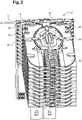
- the picture 2 schematically represents the housing 2 in a particular embodiment where, as in the embodiment of the figure 1 , the housing 2 comprises two organizers 28 for bare fiber management located respectively on the sides 24 and 26 of the housing.
- the organizers 28 for bare fiber management each have a series of side inputs 29 of optical fibers F.
- optical fibers F are included in single-fiber optical cables, that is to say optical cables composed of a single light guide.
- an optical fiber F entering the junction box 2 via a side entry 29 may be contained in a tube T.
- a tube T For greater clarity of the drawing, only a tube T has been shown.
- the tube T shown enters the housing 2 through a side entrance 29 which is located at the top of the housing 2, in the organizer 28 for management of bare fibers located on the side 24 of the housing 2.
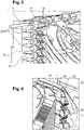
- the picture 3 is a partial enlarged view of the housing 2 of the figure 2 seen from a different angle, showing part of the side entrance series 29 in more detail.
- the organizer 28 for managing bare fibers located on each side 24, 26 of the box 2 comprises a plurality of lugs 30 for holding optical fibers.
- the tabs 30 are arranged along the organizer 28 for management of bare fibers, on at least a part of the latter. They are arranged spaced from each other. The distances between two neighboring tabs 30 are determined according to the application considered, are not necessarily identical, but can be, as is the case in the illustrated embodiment.
- the figure 4 shows another embodiment of case 2.
- the organizer 28 for managing bare fibers comprises one or more parts 40 each forming a bridge.
- Each bridge delimits on the one hand, the first region R1, on a first side of the bridge, where optical fibers F travel in the organizer 28 for management of bare fibers along the sides 24, 26 following the vertical flow (only the side 26 is visible in the drawing) and on the other hand, the second region R2, on a second side of the bridge, where optical fibers F enter the organizer 28 for management of bare fibers following the horizontal flow, via a comb 42 provided in addition to the bridge, the comb 42 cooperating with the part 40 in order to facilitate the reception and securing of the incoming fiber optic modules F.
- the region R1 of a first side of the bridge is on the bridge and the region R2 of a second side of the bridge is next to the bridge.
- the vertical optical fibers F on the one hand (that is to say traveling along the column of cassettes 10, by the top of the bridge in region R1) and the incoming fibers and secured to the comb, on the other hand (in the R2 region and from below the bridge) can intersect without mixing or interfering.
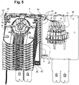
- FIG 5 illustrates another embodiment of the housing 2, in which the housing 2 further comprises a patch panel 50 where the connection of optical F fibers to C connectors.
- figure 5 shows more particularly the path of an optical fiber F between a splicing cassette 10 and this patch panel 50.
- the housing 2 comprises at its base 20 additional inputs 52 of optical fibers F.
- these additional inputs 52 are in the form of a support comb.
- the organizer 28 for managing bare fibers has a side wall P comprising one or more passages 54 adapted to the routing of optical fibers F which come out of the splicing cassettes 10 .
- the housing 2 comprises one or more columns each consisting of a plurality of splicing cassettes 10 and an area B for patching optical fibers F on the patch panel 50 .
- the passage 54 is adapted to the routing of optical fibers F directly between one of the columns of cassettes 10 and the patching zone B, for example along a plane substantially parallel to the base 20 of the housing 2, that is to say for example substantially horizontally, if the base 20 of the housing 2 rests on a horizontal surface.
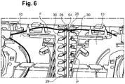
- the figure 6 shows another embodiment, where the box 2 comprises a number of columns greater than or equal to two (a part of two of these columns is visible in the drawing), each column consisting of a plurality of cassettes 10.
- the passage 54 is adapted to the routing of optical fibers F directly between two of these columns, for example along a plane substantially parallel to the base 20 of the housing 2, that is to say for example substantially horizontally, if the base 20 of the housing 2 rests on a horizontal surface.
- the passage 24 can for example be located between two successive lugs 30 of the series of lugs.
Landscapes
- Physics & Mathematics (AREA)
- General Physics & Mathematics (AREA)
- Optics & Photonics (AREA)
- Light Guides In General And Applications Therefor (AREA)
Applications Claiming Priority (1)
| Application Number | Priority Date | Filing Date | Title |
|---|---|---|---|
| FR2014209A FR3118497A1 (fr) | 2020-12-29 | 2020-12-29 | Boîtier de raccordement optique |
Publications (1)
| Publication Number | Publication Date |
|---|---|
| EP4024109A1 true EP4024109A1 (de) | 2022-07-06 |
Family
ID=74871599
Family Applications (1)
| Application Number | Title | Priority Date | Filing Date |
|---|---|---|---|
| EP21207602.0A Ceased EP4024109A1 (de) | 2020-12-29 | 2021-11-10 | Optischer anschlusskasten |
Country Status (2)
| Country | Link |
|---|---|
| EP (1) | EP4024109A1 (de) |
| FR (1) | FR3118497A1 (de) |
Cited By (1)
| Publication number | Priority date | Publication date | Assignee | Title |
|---|---|---|---|---|
| WO2025109373A1 (en) * | 2023-11-21 | 2025-05-30 | CommScope Connectivity Belgium BV | Telecommunications equipment with pre-cabled splice trays |
Citations (6)
| Publication number | Priority date | Publication date | Assignee | Title |
|---|---|---|---|---|
| US4840449A (en) * | 1988-01-27 | 1989-06-20 | American Telephone And Telegraph Company, At&T Bell Laboratories | Optical fiber splice organizer |
| US5353367A (en) * | 1993-11-29 | 1994-10-04 | Northern Telecom Limited | Distribution frame and optical connector holder combination |
| US5402515A (en) * | 1994-03-01 | 1995-03-28 | Minnesota Mining And Manufacturing Company | Fiber distribution frame system, cabinets, trays and fiber optic connector couplings |
| GB2286060A (en) * | 1994-01-14 | 1995-08-02 | Augat Limited | Optical fibre splice tray |
| US6282360B1 (en) * | 1999-02-04 | 2001-08-28 | Alcatel | Optical fiber organizer |
| US20100183274A1 (en) * | 2006-09-13 | 2010-07-22 | Herve Brunet | Fiber circuit management system with splice tray |
-
2020
- 2020-12-29 FR FR2014209A patent/FR3118497A1/fr active Pending
-
2021
- 2021-11-10 EP EP21207602.0A patent/EP4024109A1/de not_active Ceased
Patent Citations (6)
| Publication number | Priority date | Publication date | Assignee | Title |
|---|---|---|---|---|
| US4840449A (en) * | 1988-01-27 | 1989-06-20 | American Telephone And Telegraph Company, At&T Bell Laboratories | Optical fiber splice organizer |
| US5353367A (en) * | 1993-11-29 | 1994-10-04 | Northern Telecom Limited | Distribution frame and optical connector holder combination |
| GB2286060A (en) * | 1994-01-14 | 1995-08-02 | Augat Limited | Optical fibre splice tray |
| US5402515A (en) * | 1994-03-01 | 1995-03-28 | Minnesota Mining And Manufacturing Company | Fiber distribution frame system, cabinets, trays and fiber optic connector couplings |
| US6282360B1 (en) * | 1999-02-04 | 2001-08-28 | Alcatel | Optical fiber organizer |
| US20100183274A1 (en) * | 2006-09-13 | 2010-07-22 | Herve Brunet | Fiber circuit management system with splice tray |
Cited By (1)
| Publication number | Priority date | Publication date | Assignee | Title |
|---|---|---|---|---|
| WO2025109373A1 (en) * | 2023-11-21 | 2025-05-30 | CommScope Connectivity Belgium BV | Telecommunications equipment with pre-cabled splice trays |
Also Published As
| Publication number | Publication date |
|---|---|
| FR3118497A1 (fr) | 2022-07-01 |
Similar Documents
| Publication | Publication Date | Title |
|---|---|---|
| CN107065087B (zh) | 具有串联布置的光学连接终端的光纤网络架构 | |
| CN102334057B (zh) | 具有光纤装置的可重构多区光纤网络结构 | |
| US7496269B1 (en) | Fiber optic enclosure | |
| US7493003B2 (en) | Modular optical wall box enclosure | |
| US20110293277A1 (en) | Reconfigurable multi-zoned fiber optic network architecture having fiber optic devices | |
| FR2682488A1 (fr) | Tete de cables modulaire a fibres optiques de grande capacite . | |
| US20260086288A1 (en) | Compact splice enclosure with improved access to adapters | |
| EP0202994A1 (de) | Verzweigervorrichtung für optische Faserkabel | |
| EP4024109A1 (de) | Optischer anschlusskasten | |
| EP2463697B1 (de) | Kassette zum Aufwickeln von Fasern und Aufrechterhalten der Spleißungen | |
| US12353040B2 (en) | Adapter configured to permit a heat shrink splice holder portion of a fiber splice cassette to hold a mechanical crimp splice protector | |
| US20250306323A1 (en) | Fiber distribution hub including sealed splice module | |
| AU2009201625B2 (en) | Optical connection terminal having port mapping scheme | |
| EP2386893A1 (de) | Anschlusskasten für Glasfaserkabel | |
| AU2015203506A1 (en) | Reconfigurable multi-zoned fiber optic network architecture having fiber optic devices | |
| AU2015268676A1 (en) | Fiber optic network architecture having optical connection terminals in series arrangement |
Legal Events
| Date | Code | Title | Description |
|---|---|---|---|
| PUAI | Public reference made under article 153(3) epc to a published international application that has entered the european phase |
Free format text: ORIGINAL CODE: 0009012 |
|
| STAA | Information on the status of an ep patent application or granted ep patent |
Free format text: STATUS: THE APPLICATION HAS BEEN PUBLISHED |
|
| AK | Designated contracting states |
Kind code of ref document: A1 Designated state(s): AL AT BE BG CH CY CZ DE DK EE ES FI FR GB GR HR HU IE IS IT LI LT LU LV MC MK MT NL NO PL PT RO RS SE SI SK SM TR |
|
| STAA | Information on the status of an ep patent application or granted ep patent |
Free format text: STATUS: REQUEST FOR EXAMINATION WAS MADE |
|
| 17P | Request for examination filed |
Effective date: 20230109 |
|
| RBV | Designated contracting states (corrected) |
Designated state(s): AL AT BE BG CH CY CZ DE DK EE ES FI FR GB GR HR HU IE IS IT LI LT LU LV MC MK MT NL NO PL PT RO RS SE SI SK SM TR |
|
| STAA | Information on the status of an ep patent application or granted ep patent |
Free format text: STATUS: EXAMINATION IS IN PROGRESS |
|
| 17Q | First examination report despatched |
Effective date: 20240213 |
|
| RAP1 | Party data changed (applicant data changed or rights of an application transferred) |
Owner name: AGINODE GROUP |
|
| STAA | Information on the status of an ep patent application or granted ep patent |
Free format text: STATUS: THE APPLICATION HAS BEEN REFUSED |
|
| 18R | Application refused |
Effective date: 20250507 |