EP4024604A1 - Magische breitband-mikrowellen-verbindung in t-form - Google Patents
Magische breitband-mikrowellen-verbindung in t-form Download PDFInfo
- Publication number
- EP4024604A1 EP4024604A1 EP21215865.3A EP21215865A EP4024604A1 EP 4024604 A1 EP4024604 A1 EP 4024604A1 EP 21215865 A EP21215865 A EP 21215865A EP 4024604 A1 EP4024604 A1 EP 4024604A1
- Authority
- EP
- European Patent Office
- Prior art keywords
- microwave
- junction
- magic
- waveguides
- plane
- Prior art date
- Legal status (The legal status is an assumption and is not a legal conclusion. Google has not performed a legal analysis and makes no representation as to the accuracy of the status listed.)
- Granted
Links
Images


Classifications
-
- H—ELECTRICITY
- H01—ELECTRIC ELEMENTS
- H01P—WAVEGUIDES; RESONATORS, LINES, OR OTHER DEVICES OF THE WAVEGUIDE TYPE
- H01P5/00—Coupling devices of the waveguide type
- H01P5/12—Coupling devices having more than two ports
- H01P5/16—Conjugate devices, i.e. devices having at least one port decoupled from one other port
- H01P5/19—Conjugate devices, i.e. devices having at least one port decoupled from one other port of the junction type
- H01P5/20—Magic-T junctions
-
- H—ELECTRICITY
- H01—ELECTRIC ELEMENTS
- H01P—WAVEGUIDES; RESONATORS, LINES, OR OTHER DEVICES OF THE WAVEGUIDE TYPE
- H01P11/00—Apparatus or processes specially adapted for manufacturing waveguides or resonators, lines, or other devices of the waveguide type
- H01P11/001—Manufacturing waveguides or transmission lines of the waveguide type
- H01P11/002—Manufacturing hollow waveguides
-
- Y—GENERAL TAGGING OF NEW TECHNOLOGICAL DEVELOPMENTS; GENERAL TAGGING OF CROSS-SECTIONAL TECHNOLOGIES SPANNING OVER SEVERAL SECTIONS OF THE IPC; TECHNICAL SUBJECTS COVERED BY FORMER USPC CROSS-REFERENCE ART COLLECTIONS [XRACs] AND DIGESTS
- Y02—TECHNOLOGIES OR APPLICATIONS FOR MITIGATION OR ADAPTATION AGAINST CLIMATE CHANGE
- Y02P—CLIMATE CHANGE MITIGATION TECHNOLOGIES IN THE PRODUCTION OR PROCESSING OF GOODS
- Y02P10/00—Technologies related to metal processing
- Y02P10/25—Process efficiency
Definitions
- the invention lies in the field of microwave components in the broad sense, mainly for conducted wave technology. It relates more particularly to the improvement of a junction of microwave waveguides known to those skilled in the art under the name of magic T junction, which can be used in different types of microwave components, for example in the field of space. , telecommunications, radio links, etc.
- Microwave junctions are well-known three-port components made from waveguides and used to combine or split microwave signals.
- the picture 1a represents a so-called E- plane T microwave junction , or E-plane tee. It comprises three ports through which signals can be injected or extracted. It is composed of an arm 101 called difference arm, and two collinear arms 102 and 103, called lateral arms, the three arms meeting at the same point so as to form a T.
- the T-profile appears through the short side of the waveguides, which is in a plane parallel to the electric field (E-field).
- a microwave signal injected on the difference arm 101 of the plane T-junction E is found divided into two identical signals but in phase opposition on the side arms 102 and 103. Conversely, the injection of two signals on the arms 102 and 103 results in the difference of these signals on the difference arm 101.
- the figure 1b represents a so-called H-plane T microwave junction , or H-plane tee. It comprises three ports through which signals can be injected or extracted. It is composed of an arm 111, called sum arm, and two collinear arms 112 and 113, called lateral arms, the three arms meeting at the same point so as to form a T.
- the T-profile appears through the long side of the waveguides, which is in a plane parallel to the magnetic field (H-field).
- a microwave signal injected on the sum arm 111 of the H-plane T-junction finds itself divided into two identical signals and in phase on the side arms 112 and 113. Conversely, the injection of a signal on the side arms 112 and 113 results in the sum of these signals on the sum arm 111.
- E-plane and H-plane T-junctions can be used as couplers or splitters.
- their three-arm structure means that the adaptation of the ports is imperfect. It is known from the state of the art to introduce metallic elements modifying the geometry of the junctions in order to partly improve the adaptation of the ports or the operating frequency band of the junction, for example the pad 120 of the picture 1a and plot 121 of the figure 1b , or adaptation screws positioned at the junction of the three arms, but without it being possible to achieve significant levels of adaptation.
- microwave magic T junctions ( Magic Tee ) , magic tee, or hybrid T. These junctions are four-port junctions performing both the E-plane T-junction function and the H-plane T-junction function.
- the figure 1c represents a so-called magic T microwave junction. It includes four ports through which signals can be injected or extracted. It is composed of two perpendicular arms 131 and 132, called difference arm and sum arm, and of two collinear arms 133 and 134, called lateral arms. The four waveguides meet at the same point. Together, difference arm 131, and side arms 133 and 134 perform the E-plane microwave T-junction function. Sum arm 132 and side arms 133 and 134 perform the H-plane microwave T-junction function.
- the injection of a signal on the difference arm 131 of the magic T-junction produces two identical signals in phase opposition on the side arms 133 and 134. It does not propagate on the sum arm 132 because the symmetry properties of the Magic T gives it very good isolation between the sum and difference arms (typically greater than 50dB). Similarly, the injection of a signal on the sum arm 132 of the magic T-junction produces two identical and in-phase signals on the side arms 133 and 134. This signal does not propagate on the difference arm 131.
- the magic T-shaped microwave junction therefore simultaneously performs the functions of E-plane coupler and H-plane coupler. It is used in particular for mixing waves in microwave transmitters/receivers. Another common application is its use as a microwave power splitter, for example connecting the difference port to a load configured to dissipate the signal passed to it since, unlike three-port T-junctions, the microwave T-junction magic presents very good levels of adaptation on all its ports.
- microwave magic T junctions according to the state of the art is that they only operate on a limited frequency band, typically around 5% of the carrier frequency when good adaptation is desired. of the four ports.
- the magic microwave T-junction When the magic microwave T-junction is used as a power divider by loading one of its ports, it is possible to modify its properties by tolerating a less efficient matching for the loaded port, so as to improve the matching of the other ports . However, this case transfers the complexity of production to the load, which must be of better quality in order to absorb the energy transmitted on an unsuitable port.
- An object of the invention is therefore to respond to the problems posed by the state of the art by describing a microwave magic T junction that is simple to produce and has good levels of adaptation of the ports (typically greater than -25 dB) , good isolation of the sum and difference ports (typically greater than -50 dB) and a wide operating frequency band (typically greater than or equal to 15% of the center frequency).
- the difference arm of the first microwave junction forms the difference arm of the magic microwave T-junction
- the sum arm of the second microwave junction forms the sum arm of the microwave T-junction magic
- the second waveguides form the side arms of the magic T-junction microwave.
- a metallic element is arranged in the first microwave junction at the junction point between the difference arm and the two collinear arms so as to adjust its properties and/or in the second microwave junction at the junction point between the sum arm and the two collinear arms so as to adjust its properties.
- a metallic element is placed at each junction between the first waveguides and the second waveguides, symmetrically with respect to the reference plane.
- the junctions between the collinear arms of the first microwave junction and the first waveguides and/or the junctions between the collinear arms of the second microwave junction and the first waveguides have geometric shapes or sizes configured to improve the impedance matching characteristics of the microwave magic T junction.
- a microwave power splitter comprising a microwave magic T-junction according to the invention, one of the ports of which is terminated by a load.
- the magic T junction according to the invention can be used to produce a network of microwave beamformers comprising a plurality of magic T microwave junctions according to the invention mounted in cascade, one of the ports of each junction being terminated by a charge.
- the invention also relates to a computer program product comprising a series of computer-executable instructions which, when executed by a processor, allow the processor to control a metal additive manufacturing device to make a magic microwave T-junction according to the invention, or a plurality of magic T microwave junctions according to the invention mounted in cascade.
- the microwave magic T-junction according to the invention achieves the desired effect by separating the single junction from the magic T-junctions according to the state of the art into a plane E three-port T-junction and a three-port T-junction. H plane.
- This duplication solves the problem of the joint optimization of the "sum” and "difference" ports, which can then be optimized independently of each other, without the improvements made to one affecting the other.
- the magic T-junction according to the invention can be optimized very simply and very efficiently, since all the parameters are accessible and can be adjusted. This makes it possible to give it a greater bandwidth and a better adaptation than the magic T-junctions according to the state of the art.
- its four-port structure guarantees good adaptation of all the ports and good isolation of the sum and difference ports.
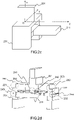
- the figure 2a shows a first embodiment of a magic T microwave junction according to the invention, in a front view. Like all magic T-junctions, it includes a sum arm 211, a difference arm 201, and two side arms 231 and 232.
- the assembly forms a magic T-shaped microwave junction of which the difference arm 201 of the first E-plane T-junction constitutes the difference arm, the sum arm 211 of the second H-plane T-junction constitutes the sum arm, and the two second arms 231 and 232 constitute the side arms.
- the device of the figure 2a is described in the form of an assembly of separate junctions and waveguides, this description is purely functional, with the aim of presenting the characteristics of the junction according to the invention.
- Several waveguides can be made in one piece, for example the collinear arms of the microwave junctions (for example the guides 202 and 203), or the first and second waveguides (for example the guides 221 and 231) .
- the device can also be produced in several parts produced by milling and then assembled, or in a single block, for example by metal additive manufacturing.
- Additive manufacturing refers to a three-dimensional printing process in which successive layers of material are fused together to produce a component.
- the material used is a metallic material.
- Metal additive manufacturing makes it simple to produce parts that would otherwise have been complex or even impossible to produce. It makes it possible to manufacture components from a three-dimensional computer model of the component.
- the invention therefore relates both to a microwave magic T junction according to the invention, whether or not produced by additive manufacturing, but also to a method of producing the microwave junction using additive manufacturing, as well as to the computer model containing the three-dimensional design of the microwave junction, i.e. its geometric representation.
- This computer model can then be converted into a sequence of instructions executable by a processor to control a metal additive manufacturing device and produce the product corresponding to the model.
- the device according to the invention forms a balanced and symmetrical assembly, with particularly advantageous properties in terms of adaptation and isolation of the ports.
- the figure 2b represents the orientation of the electric field of signals injected respectively on the difference input 201 and on the sum input 211 of a magic T microwave junction such as that represented in figure 2a .
- the solid arrow lines represent the direction of the electric field of a signal injected on the difference port 201 of the microwave junction.
- the signal propagates in the form of two identical signals and in phase opposition in the collinear arms 202 and 203. Due to the symmetry of the first waveguides 221 and 222, the signals then continue to propagate identically.
- the waveguides 221, 212 and 231 (and respectively 222, 213 and 232) together form an E-plane T-junction, so that the signals transmitted in the waveguides 212 and 213 are identical and in phase opposition. .
- These signals cancel out during their recombination in the sum port 211 of the second microwave junction, which guarantees significant isolation of the sum port 211 with respect to the signal injected on the difference port 201.
- the dotted lines represent the direction of the electric field of a signal injected on the sum port 211 of the microwave junction.
- the signal propagates in the form of two identical signals and in phase in the collinear arms 212 and 213. Due to the symmetry of the waveguides, the signals which arrive in the arms 202 and 203 are identical and in phase. They cancel out during their recombination in the difference arm 201 of the first microwave junction, thus guaranteeing the isolation of the difference port with respect to the signal injected on the sum port.
- the figure 2c is a perspective view of the device of the figure 2a , on which it is possible to distinguish the difference arm 201, the sum arm 211 and the lateral arm 231.
- the 2d figure is a perspective view of the device of the microwave magic T-junction of the figure 2a , in which metal elements have been added to improve performance.
- pads 241 and 242 have been added at the point of connection of the waveguides of the first and the second three-arm microwave T-junction. Adding pads to the junction point of the arms of a three-arm microwave junction makes it possible to modify its operating properties, and in particular to widen the operating band and to adjust the adaptation of the ports. As indicated previously, the addition of such pads is not very effective in microwave magic T junctions according to the state of the art, because the improvements made in one plane tend to degrade the characteristics in the other plane. This is not the case for the microwave magic T-junction according to the invention, since the E-plane T-junction and the H-plane T-junction are separate.
- the microwave magic T junction according to the invention can therefore be adjusted very easily according to the performance sought, in particular in terms of bandwidth of operation and adaptation level of the ports.
- a similar result could be obtained by using metal elements equivalent to the pads such as for example adjustment screws.
- the assembly formed by the waveguides 221, 231 and 212 can be likened to a T plane E junction, which can also be optimized in band and in adaptation by adding metal elements such as the pad 243 (and respectively 244).
- the junctions between the various waveguides can be optimized so as to improve the impedance matching, for example by adding irises, steps on the elbows (as is the case at 251 for the connection between the waveguides 202 and 221, or at 252 for the connection between the waveguides 203 and 222), or by varying the dimensions of the sections of the waveguides.
- the figure 2e gives the port matching levels obtained for a microwave magic T-junction according to the embodiment given in 2d figure , obtained by simulation.
- Curve 261 corresponds to the adaptation on the sum port
- curve 262 corresponds to the adaptation for the difference port
- curve 263 corresponds to the adaptation on the two side ports (the curves corresponding to each of the side ports are identical by the symmetry properties of the device). It is observed that the adaptation of the four ports of the magic T-junction is better than -27 dB on the 18.3 GHz - 21.3 GHz band, i.e. for a bandwidth of approximately 15% of the carrier frequency, which corresponds to the desired performance. In addition, the isolation between the sum port and the difference port is very good since it is less than -75 dB over the whole of this frequency band.
- the microwave magic T junction according to the invention therefore makes it possible to obtain levels of adaptation of the ports and operating bandwidths much higher than those obtained with the microwave magic T junctions according to the state of the art, while maintaining very good port isolation.
- the independence of the T plane E junction and of the T plane H junction means that the overall performance can be adapted to the context of use by varying the sizes and shapes of the metal elements inserted into the device. This optimization can be carried out very simply and quickly on a simulator according to the techniques known to those skilled in the art for three-port microwave junctions.
- the device according to the invention has the advantage of being geometrically very simple and very compact, therefore light and compact, its footprint being only very slightly greater than that of a magic T depending on the state art.
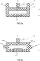
- the devices 3a to 3d present different embodiments of a magic T microwave junction according to the invention, given by way of illustration only.
- the list of proposed configurations is not exhaustive: the device according to the invention can be implemented as soon as it comprises a microwave junction with three T-plane E ports and a microwave junction with three T-plane H ports separated and arranged so as to be each symmetrical with respect to the same plane, and the ends of the collinear arms of which are connected by waveguides arranged symmetrically with respect to the plane in which waveguides forming the arms are fixed sides of the microwave junction. A very large number of variations is therefore possible when these conditions are met.
- the second waveguides 301 and 302 are arranged above the first waveguides, so as to extend them.
- the second waveguides 311 and 312 are arranged on the sides of the waveguides 221 and 222.
- the second waveguides 321 and 322 are arranged under the first waveguides 221 and 222, so as to extend them, but are not aligned with the latter. However, they remain arranged symmetrically with respect to the plane xOz.
- the second waveguides 331 and 332 are arranged on one edge of the first waveguides 221 and 222, which corresponds to an off-center version of the device of the figure 3b .
- the collinear arms of the first and of the second junction are of identical sizes.
- the invention can also be implemented when the collinear arms of the E-plane microwave junction are of different sizes from the collinear arms of the H-plane microwave junction, provided that the conditions of symmetry are respected.
- the second waveguides are positioned in the E plane, but could also be positioned in the H plane, for example by extending in a direction parallel to the difference arm 211.
- metallic elements can be added at the E-plane junction and/or the H-plane junction to adapt their performance, like the pads 241 and 242 of the 2d figure .
- Metallic elements can also be added to the junction between the first and the second waveguides so as to adjust the matching of the side ports and the bandwidth of the magic T-junction according to the invention, in the manner of the studs 243 and 244 of the 2d figure .
- the studs 243 and 244 must however be symmetrical with respect to the plane xOz.
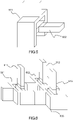
- the figure 4 presents another embodiment of a magic T-shaped microwave junction according to the invention, in which the three-port microwave junctions are arranged side by side in the yOz plane, and no longer superimposed, always in such a way that each of them it has its two collinear arms arranged symmetrically with respect to the plane xOz.
- the junctions between the collateral arms of the first and of the second microwave junction and the first waveguides are implemented in the form of steps making it possible to improve the adaptation of the ports, such as for example the steps 440 on the figure 4 .
- the representation of the figure 4 can be modified in many ways based on the teachings previously provided, in particular as regards the positioning of the second waveguides.
- the microwave junction according to the invention is very compact and has a very good adaptation of all the ports, over a wide frequency band. It can therefore be used in a large number of applications, such as for example as a compact power divider for microwave equipment.
- the figure 5 represents an embodiment of a power divider involving a microwave junction according to an embodiment of the invention. It comprises a magic T microwave junction according to the invention 501, one of whose ports, here the sum port, is terminated by a load 502.
- the loads ( load or termination load in English) are microwave components intended to transform an electromagnetic energy which is transmitted to them in thermal energy in order to dissipate it. They make it possible to make disappear signals having no interest. For example, they are frequently found in association with couplers, in order to direct the power of the signal, or with circulators configured to play the role of insulators.
- the most widespread state-of-the-art solution for carrying out a microwave load consists of inserting an absorbent material such as silicon carbide (SIC) or Eccosorb TM into a short-circuited waveguide portion, rigid material composed of bars or sheets of magnetically charged epoxies.
- SIC silicon carbide
- Eccosorb TM TM
- a divisor of power can therefore be achieved easily by connecting such a load at the output of one of the ports of the isolator according to the invention.
- the magic T microwave junction according to the invention can be produced in a single piece by metal additive manufacturing, which has the advantage of allowing it to be produced quickly, at low cost and in large quantities.
- certain components such as for example the beamforming networks of a network antenna, for satellite or for any other application requiring the use of an antenna whose beam can be digitally directed, require a very large number of cascaded power dividers.
- the manufacturing complexity of the junction is therefore an important criterion.
- additive manufacturing makes it possible to produce in a single block a series of magic T-junctions intended to be connected to loads to form an array of beamformers.
- the figure 6 shows a beamformer array using microwave magic T junctions according to one embodiment of the invention.
- it comprises three microwave junctions according to the invention 601, 602 and 603 mounted in cascade, one of the ports of which is loaded by a load 611, 612 and 613 in order to achieve a beamformer.
- Such a network of cascaded microwave junctions can be manufactured very quickly and at low cost in additive manufacturing, while exhibiting excellent performance.
- the computer model is a file which can be obtained by software modeling (in English Computer Aided Design, or CAD) and/or by scanning the surface of the microwave junction according to the invention (or network of junctions) to measure its surface configuration (in English scanning ) .
- Many file formats are possible, such as Stereolithography type files or "Standard Tessellation Language" (.stl files), Additive Manufacturing File (.amf files), AutoCad (.dwg files), Blender (.blend files), Parasolid (.x_t files), 3D Manufacturing Format (.3mf files), Autodesk (3ds files), Collada (.dae files) and Wavefront (.obj files), among others.
- the electronic file can be saved in different formats, and saved on a storage medium capable of being read by a computer.
- the electronic file can be converted into a set of instructions executable by a processor, allowing it to control an additive manufacturing device in order to produce the junction or the network of junctions according to the geometric arrangement considered.
- the conversion may consist of converting the file into a set of layers to be formed sequentially by the additive manufacturing device.
- the additive manufacturing device (3D printer) executes the instructions transmitted to it to manufacture the load according to the invention.
- the invention therefore also relates to a computer program comprising a series of executable instructions which, when executed by a processor, allow the processor to control a metal additive manufacturing device to make a magic microwave T-junction according to the invention, as shown in figure 5 , or a network of cascaded magic T-shaped microwave junctions, as shown in figure 6 .
- the junction and the network of junctions can be associated with one or more loads so as to form a power divider or a network of beamformers as described previously.
Landscapes
- Engineering & Computer Science (AREA)
- Manufacturing & Machinery (AREA)
- Control Of Motors That Do Not Use Commutators (AREA)
- Variable-Direction Aerials And Aerial Arrays (AREA)
- Constitution Of High-Frequency Heating (AREA)
Applications Claiming Priority (1)
| Application Number | Priority Date | Filing Date | Title |
|---|---|---|---|
| FR2014259A FR3118537B1 (fr) | 2020-12-30 | 2020-12-30 | Jonction hyperfréquence en té magique large bande |
Publications (2)
| Publication Number | Publication Date |
|---|---|
| EP4024604A1 true EP4024604A1 (de) | 2022-07-06 |
| EP4024604B1 EP4024604B1 (de) | 2025-09-03 |
Family
ID=75108529
Family Applications (1)
| Application Number | Title | Priority Date | Filing Date |
|---|---|---|---|
| EP21215865.3A Active EP4024604B1 (de) | 2020-12-30 | 2021-12-20 | Magische breitband-mikrowellen-verbindung in t-form |
Country Status (4)
| Country | Link |
|---|---|
| US (1) | US12040529B2 (de) |
| EP (1) | EP4024604B1 (de) |
| CA (1) | CA3144403A1 (de) |
| FR (1) | FR3118537B1 (de) |
Families Citing this family (2)
| Publication number | Priority date | Publication date | Assignee | Title |
|---|---|---|---|---|
| CN117220002B (zh) * | 2023-09-20 | 2024-06-21 | 北京西宝电子技术有限责任公司 | 宽带波导魔t及通信系统 |
| US12512577B1 (en) * | 2023-11-06 | 2025-12-30 | Lockheed Martin Corporation | Magic tee waveguide structure with triangular impedance matching element |
Citations (4)
| Publication number | Priority date | Publication date | Assignee | Title |
|---|---|---|---|---|
| JPS58182301A (ja) * | 1982-04-20 | 1983-10-25 | Mitsubishi Electric Corp | 導波管形電力合成装置 |
| US20130314172A1 (en) | 2012-05-25 | 2013-11-28 | Government Of The United States, As Represented By The Secretary Of The Air Force | Broadband Magic Tee |
| CN206610891U (zh) * | 2017-03-31 | 2017-11-03 | 安徽四创电子股份有限公司 | 一种基于波导魔t的宽带毫米波段波导多工器 |
| CN111952706A (zh) * | 2020-08-17 | 2020-11-17 | 四川斯艾普电子科技有限公司 | 一种紧凑型波导混合合成网络 |
Family Cites Families (4)
| Publication number | Priority date | Publication date | Assignee | Title |
|---|---|---|---|---|
| US2840787A (en) * | 1952-09-11 | 1958-06-24 | Hughes Aircraft Co | Hybrid tau type waveguide junction |
| US3320553A (en) * | 1961-06-29 | 1967-05-16 | Dean D Howard | Polarization diversity antenna feed system |
| US10153536B2 (en) * | 2016-12-22 | 2018-12-11 | Raytheon Company | Magic-Y splitter |
| FR3110290B1 (fr) * | 2020-05-15 | 2022-06-03 | Thales Sa | Transducteur orthomode large bande |
-
2020
- 2020-12-30 FR FR2014259A patent/FR3118537B1/fr active Active
-
2021
- 2021-12-20 EP EP21215865.3A patent/EP4024604B1/de active Active
- 2021-12-21 US US17/557,367 patent/US12040529B2/en active Active
- 2021-12-30 CA CA3144403A patent/CA3144403A1/en active Pending
Patent Citations (4)
| Publication number | Priority date | Publication date | Assignee | Title |
|---|---|---|---|---|
| JPS58182301A (ja) * | 1982-04-20 | 1983-10-25 | Mitsubishi Electric Corp | 導波管形電力合成装置 |
| US20130314172A1 (en) | 2012-05-25 | 2013-11-28 | Government Of The United States, As Represented By The Secretary Of The Air Force | Broadband Magic Tee |
| CN206610891U (zh) * | 2017-03-31 | 2017-11-03 | 安徽四创电子股份有限公司 | 一种基于波导魔t的宽带毫米波段波导多工器 |
| CN111952706A (zh) * | 2020-08-17 | 2020-11-17 | 四川斯艾普电子科技有限公司 | 一种紧凑型波导混合合成网络 |
Non-Patent Citations (1)
| Title |
|---|
| WU JIE ET AL: "Ridged Waveguide Magic Tees Based on 3-D Printing Technology", IEEE TRANSACTIONS ON MICROWAVE THEORY AND TECHNIQUES, PLENUM, USA, vol. 68, no. 10, 15 July 2020 (2020-07-15), pages 4267 - 4275, XP011812548, ISSN: 0018-9480, [retrieved on 20201005], DOI: 10.1109/TMTT.2020.3006570 * |
Also Published As
| Publication number | Publication date |
|---|---|
| US20220209389A1 (en) | 2022-06-30 |
| EP4024604B1 (de) | 2025-09-03 |
| US12040529B2 (en) | 2024-07-16 |
| FR3118537A1 (fr) | 2022-07-01 |
| FR3118537B1 (fr) | 2023-12-22 |
| CA3144403A1 (en) | 2022-06-30 |
Similar Documents
| Publication | Publication Date | Title |
|---|---|---|
| EP2223377B1 (de) | Radiale Vorrichtung zur Leistungsverstärkung mit Phasensdispersionausgleich der Verstärkungswege | |
| EP3726642B1 (de) | Polarisationsschirm mit breitband-hochfrequenz-polarisationszelle(n) | |
| EP3073569B1 (de) | Butler matrix compact, bi-dimensionales planare beam-former und planarantenne mit einer solchen butler matrix | |
| EP3843202A1 (de) | Horn für eine zirkular polarisierte duale ka-band-satellitenantenne | |
| EP4024604B1 (de) | Magische breitband-mikrowellen-verbindung in t-form | |
| EP3179551B1 (de) | Kompakteinheit zur doppelpolarisierten ansteuerung für ein strahlungselement einer antenne, und kompaktes netz, das mindestens vier kompakte ansteuerungseinheiten umfasst | |
| FR2652197A1 (fr) | Transformateurs du type symetrique-dissymetrique perfectionnes. | |
| EP3086409B1 (de) | Strukturmodul einer antenne, in das leuchtquellen zur individuellen orientierung integriert sind, leuchtpaneel, leuchtnetz und mehrfachstrahlantenne, die mindestens ein solches modul umfasst | |
| WO2003007423A1 (fr) | Antenne a couplage reactif comportant deux elements rayonnants | |
| CA2869648A1 (fr) | Repartiteur de puissance compact bipolarisation, reseau de plusieurs repartiteurs, element rayonnant compact et antenne plane comportant un tel repartiteur | |
| EP3180816B1 (de) | Mehrbandige quelle mit koaxialem horn mit monopulsnachführungsverfahren für eine reflektorantenne | |
| EP2263311A1 (de) | Raumleistungsverstärker mit mehreren quellen | |
| EP3664214B1 (de) | Mehrfachzugriff strahlelemente | |
| EP4092831B1 (de) | Antenne mit lückenhaftem verteilungsnetz | |
| EP4156406A1 (de) | Mikroschaltung mit integriertem wellenleiter | |
| CA3104044A1 (fr) | Excitateur radiofrequence d'antenne en reception et transmission | |
| EP3910729B1 (de) | Breitband-orthomodus-wandler | |
| EP0465994A1 (de) | Mikrowellenmodul des Streifenleitungstyps | |
| EP3721501A1 (de) | Mikrowellen-bauelement und zugehöriges herstellungsverfahren | |
| EP0489632A1 (de) | Mikrowellen-Hybridkoppler mit 3xN Eingängen und 3xM Ausgängen, insbesondere 3x3 Koppler | |
| FR3073085B1 (fr) | Ensemble guide d'onde et procede d'assemblage associe | |
| EP3955374B1 (de) | Schaltung mit zirkulatorfunktion mit siw-technologie, entsprechender sende-/empfangskanal und radar | |
| WO2025247699A1 (fr) | Cellule polarisante active, réseau transmetteur et antennes d'émission et de réception radio | |
| FR2544554A1 (fr) | Element rayonnant ou recepteur de signaux hyperfrequences a polarisations circulaires gauche et droite et antenne plane comprenant un reseau de tels elements juxtaposes | |
| WO2020127424A1 (fr) | Coupleur hyperfrequence bidirectionnel comprenant deux guides d'onde paralleles, a double nervure |
Legal Events
| Date | Code | Title | Description |
|---|---|---|---|
| PUAI | Public reference made under article 153(3) epc to a published international application that has entered the european phase |
Free format text: ORIGINAL CODE: 0009012 |
|
| STAA | Information on the status of an ep patent application or granted ep patent |
Free format text: STATUS: THE APPLICATION HAS BEEN PUBLISHED |
|
| AK | Designated contracting states |
Kind code of ref document: A1 Designated state(s): AL AT BE BG CH CY CZ DE DK EE ES FI FR GB GR HR HU IE IS IT LI LT LU LV MC MK MT NL NO PL PT RO RS SE SI SK SM TR |
|
| STAA | Information on the status of an ep patent application or granted ep patent |
Free format text: STATUS: REQUEST FOR EXAMINATION WAS MADE |
|
| 17P | Request for examination filed |
Effective date: 20221110 |
|
| RBV | Designated contracting states (corrected) |
Designated state(s): AL AT BE BG CH CY CZ DE DK EE ES FI FR GB GR HR HU IE IS IT LI LT LU LV MC MK MT NL NO PL PT RO RS SE SI SK SM TR |
|
| GRAP | Despatch of communication of intention to grant a patent |
Free format text: ORIGINAL CODE: EPIDOSNIGR1 |
|
| STAA | Information on the status of an ep patent application or granted ep patent |
Free format text: STATUS: GRANT OF PATENT IS INTENDED |
|
| INTG | Intention to grant announced |
Effective date: 20250416 |
|
| GRAS | Grant fee paid |
Free format text: ORIGINAL CODE: EPIDOSNIGR3 |
|
| GRAA | (expected) grant |
Free format text: ORIGINAL CODE: 0009210 |
|
| STAA | Information on the status of an ep patent application or granted ep patent |
Free format text: STATUS: THE PATENT HAS BEEN GRANTED |
|
| AK | Designated contracting states |
Kind code of ref document: B1 Designated state(s): AL AT BE BG CH CY CZ DE DK EE ES FI FR GB GR HR HU IE IS IT LI LT LU LV MC MK MT NL NO PL PT RO RS SE SI SK SM TR |
|
| REG | Reference to a national code |
Ref country code: CH Ref legal event code: EP |
|
| REG | Reference to a national code |
Ref country code: DE Ref legal event code: R096 Ref document number: 602021037642 Country of ref document: DE |
|
| REG | Reference to a national code |
Ref country code: IE Ref legal event code: FG4D Free format text: LANGUAGE OF EP DOCUMENT: FRENCH |
|
| REG | Reference to a national code |
Ref country code: NL Ref legal event code: MP Effective date: 20250903 |
|
| PGFP | Annual fee paid to national office [announced via postgrant information from national office to epo] |
Ref country code: DE Payment date: 20251119 Year of fee payment: 5 |
|
| PGFP | Annual fee paid to national office [announced via postgrant information from national office to epo] |
Ref country code: GB Payment date: 20251113 Year of fee payment: 5 |
|
| PG25 | Lapsed in a contracting state [announced via postgrant information from national office to epo] |
Ref country code: NO Free format text: LAPSE BECAUSE OF FAILURE TO SUBMIT A TRANSLATION OF THE DESCRIPTION OR TO PAY THE FEE WITHIN THE PRESCRIBED TIME-LIMIT Effective date: 20251203 |
|
| REG | Reference to a national code |
Ref country code: LT Ref legal event code: MG9D |
|
| PGFP | Annual fee paid to national office [announced via postgrant information from national office to epo] |
Ref country code: AT Payment date: 20260113 Year of fee payment: 5 |
|
| PG25 | Lapsed in a contracting state [announced via postgrant information from national office to epo] |
Ref country code: FI Free format text: LAPSE BECAUSE OF FAILURE TO SUBMIT A TRANSLATION OF THE DESCRIPTION OR TO PAY THE FEE WITHIN THE PRESCRIBED TIME-LIMIT Effective date: 20250903 |
|
| PG25 | Lapsed in a contracting state [announced via postgrant information from national office to epo] |
Ref country code: HR Free format text: LAPSE BECAUSE OF FAILURE TO SUBMIT A TRANSLATION OF THE DESCRIPTION OR TO PAY THE FEE WITHIN THE PRESCRIBED TIME-LIMIT Effective date: 20250903 |
|
| PGFP | Annual fee paid to national office [announced via postgrant information from national office to epo] |
Ref country code: FR Payment date: 20251124 Year of fee payment: 5 |
|
| PG25 | Lapsed in a contracting state [announced via postgrant information from national office to epo] |
Ref country code: GR Free format text: LAPSE BECAUSE OF FAILURE TO SUBMIT A TRANSLATION OF THE DESCRIPTION OR TO PAY THE FEE WITHIN THE PRESCRIBED TIME-LIMIT Effective date: 20251204 |
|
| PG25 | Lapsed in a contracting state [announced via postgrant information from national office to epo] |
Ref country code: SE Free format text: LAPSE BECAUSE OF FAILURE TO SUBMIT A TRANSLATION OF THE DESCRIPTION OR TO PAY THE FEE WITHIN THE PRESCRIBED TIME-LIMIT Effective date: 20250903 |
|
| PG25 | Lapsed in a contracting state [announced via postgrant information from national office to epo] |
Ref country code: LV Free format text: LAPSE BECAUSE OF FAILURE TO SUBMIT A TRANSLATION OF THE DESCRIPTION OR TO PAY THE FEE WITHIN THE PRESCRIBED TIME-LIMIT Effective date: 20250903 |
|
| PG25 | Lapsed in a contracting state [announced via postgrant information from national office to epo] |
Ref country code: BG Free format text: LAPSE BECAUSE OF FAILURE TO SUBMIT A TRANSLATION OF THE DESCRIPTION OR TO PAY THE FEE WITHIN THE PRESCRIBED TIME-LIMIT Effective date: 20250903 Ref country code: PL Free format text: LAPSE BECAUSE OF FAILURE TO SUBMIT A TRANSLATION OF THE DESCRIPTION OR TO PAY THE FEE WITHIN THE PRESCRIBED TIME-LIMIT Effective date: 20250903 |
|
| PG25 | Lapsed in a contracting state [announced via postgrant information from national office to epo] |
Ref country code: RS Free format text: LAPSE BECAUSE OF FAILURE TO SUBMIT A TRANSLATION OF THE DESCRIPTION OR TO PAY THE FEE WITHIN THE PRESCRIBED TIME-LIMIT Effective date: 20251203 |
|
| PG25 | Lapsed in a contracting state [announced via postgrant information from national office to epo] |
Ref country code: ES Free format text: LAPSE BECAUSE OF FAILURE TO SUBMIT A TRANSLATION OF THE DESCRIPTION OR TO PAY THE FEE WITHIN THE PRESCRIBED TIME-LIMIT Effective date: 20250903 |
|
| REG | Reference to a national code |
Ref country code: AT Ref legal event code: MK05 Ref document number: 1834287 Country of ref document: AT Kind code of ref document: T Effective date: 20250903 |
|
| PG25 | Lapsed in a contracting state [announced via postgrant information from national office to epo] |
Ref country code: NL Free format text: LAPSE BECAUSE OF FAILURE TO SUBMIT A TRANSLATION OF THE DESCRIPTION OR TO PAY THE FEE WITHIN THE PRESCRIBED TIME-LIMIT Effective date: 20250903 |
|
| PG25 | Lapsed in a contracting state [announced via postgrant information from national office to epo] |
Ref country code: SM Free format text: LAPSE BECAUSE OF FAILURE TO SUBMIT A TRANSLATION OF THE DESCRIPTION OR TO PAY THE FEE WITHIN THE PRESCRIBED TIME-LIMIT Effective date: 20250903 |
|
| PG25 | Lapsed in a contracting state [announced via postgrant information from national office to epo] |
Ref country code: AT Free format text: LAPSE BECAUSE OF FAILURE TO SUBMIT A TRANSLATION OF THE DESCRIPTION OR TO PAY THE FEE WITHIN THE PRESCRIBED TIME-LIMIT Effective date: 20250903 |
|
| PG25 | Lapsed in a contracting state [announced via postgrant information from national office to epo] |
Ref country code: RO Free format text: LAPSE BECAUSE OF FAILURE TO SUBMIT A TRANSLATION OF THE DESCRIPTION OR TO PAY THE FEE WITHIN THE PRESCRIBED TIME-LIMIT Effective date: 20250903 Ref country code: IT Free format text: LAPSE BECAUSE OF FAILURE TO SUBMIT A TRANSLATION OF THE DESCRIPTION OR TO PAY THE FEE WITHIN THE PRESCRIBED TIME-LIMIT Effective date: 20250903 |
|
| PG25 | Lapsed in a contracting state [announced via postgrant information from national office to epo] |
Ref country code: IS Free format text: LAPSE BECAUSE OF FAILURE TO SUBMIT A TRANSLATION OF THE DESCRIPTION OR TO PAY THE FEE WITHIN THE PRESCRIBED TIME-LIMIT Effective date: 20260103 |