EP4024725B1 - Anpassung von koordinierten hochfrequenzübertragungen und -empfängen - Google Patents
Anpassung von koordinierten hochfrequenzübertragungen und -empfängen Download PDFInfo
- Publication number
- EP4024725B1 EP4024725B1 EP21218114.3A EP21218114A EP4024725B1 EP 4024725 B1 EP4024725 B1 EP 4024725B1 EP 21218114 A EP21218114 A EP 21218114A EP 4024725 B1 EP4024725 B1 EP 4024725B1
- Authority
- EP
- European Patent Office
- Prior art keywords
- antenna
- antennas
- processing
- diversity
- platforms
- Prior art date
- Legal status (The legal status is an assumption and is not a legal conclusion. Google has not performed a legal analysis and makes no representation as to the accuracy of the status listed.)
- Active
Links
Images



Classifications
-
- H—ELECTRICITY
- H04—ELECTRIC COMMUNICATION TECHNIQUE
- H04B—TRANSMISSION
- H04B7/00—Radio transmission systems, i.e. using radiation field
- H04B7/02—Diversity systems; Multi-antenna system, i.e. transmission or reception using multiple antennas
- H04B7/04—Diversity systems; Multi-antenna system, i.e. transmission or reception using multiple antennas using two or more spaced independent antennas
- H04B7/06—Diversity systems; Multi-antenna system, i.e. transmission or reception using multiple antennas using two or more spaced independent antennas at the transmitting station
- H04B7/0613—Diversity systems; Multi-antenna system, i.e. transmission or reception using multiple antennas using two or more spaced independent antennas at the transmitting station using simultaneous transmission
- H04B7/0615—Diversity systems; Multi-antenna system, i.e. transmission or reception using multiple antennas using two or more spaced independent antennas at the transmitting station using simultaneous transmission of weighted versions of same signal
- H04B7/0617—Diversity systems; Multi-antenna system, i.e. transmission or reception using multiple antennas using two or more spaced independent antennas at the transmitting station using simultaneous transmission of weighted versions of same signal for beam forming
-
- H—ELECTRICITY
- H04—ELECTRIC COMMUNICATION TECHNIQUE
- H04B—TRANSMISSION
- H04B7/00—Radio transmission systems, i.e. using radiation field
- H04B7/02—Diversity systems; Multi-antenna system, i.e. transmission or reception using multiple antennas
- H04B7/022—Site diversity; Macro-diversity
- H04B7/024—Co-operative use of antennas of several sites, e.g. in co-ordinated multipoint or co-operative multiple-input multiple-output [MIMO] systems
-
- H—ELECTRICITY
- H04—ELECTRIC COMMUNICATION TECHNIQUE
- H04B—TRANSMISSION
- H04B7/00—Radio transmission systems, i.e. using radiation field
- H04B7/02—Diversity systems; Multi-antenna system, i.e. transmission or reception using multiple antennas
- H04B7/04—Diversity systems; Multi-antenna system, i.e. transmission or reception using multiple antennas using two or more spaced independent antennas
- H04B7/0413—MIMO systems
- H04B7/0426—Power distribution
- H04B7/043—Power distribution using best eigenmode, e.g. beam forming or beam steering
-
- H—ELECTRICITY
- H04—ELECTRIC COMMUNICATION TECHNIQUE
- H04B—TRANSMISSION
- H04B7/00—Radio transmission systems, i.e. using radiation field
- H04B7/14—Relay systems
- H04B7/15—Active relay systems
- H04B7/155—Ground-based stations
- H04B7/15528—Control of operation parameters of a relay station to exploit the physical medium
-
- H—ELECTRICITY
- H04—ELECTRIC COMMUNICATION TECHNIQUE
- H04L—TRANSMISSION OF DIGITAL INFORMATION, e.g. TELEGRAPHIC COMMUNICATION
- H04L5/00—Arrangements affording multiple use of the transmission path
- H04L5/003—Arrangements for allocating sub-channels of the transmission path
- H04L5/0053—Allocation of signalling, i.e. of overhead other than pilot signals
-
- H—ELECTRICITY
- H04—ELECTRIC COMMUNICATION TECHNIQUE
- H04W—WIRELESS COMMUNICATION NETWORKS
- H04W84/00—Network topologies
- H04W84/18—Self-organising networks, e.g. ad-hoc networks or sensor networks
-
- H—ELECTRICITY
- H04—ELECTRIC COMMUNICATION TECHNIQUE
- H04B—TRANSMISSION
- H04B7/00—Radio transmission systems, i.e. using radiation field
- H04B7/02—Diversity systems; Multi-antenna system, i.e. transmission or reception using multiple antennas
- H04B7/022—Site diversity; Macro-diversity
- H04B7/026—Co-operative diversity, e.g. using fixed or mobile stations as relays
-
- H—ELECTRICITY
- H04—ELECTRIC COMMUNICATION TECHNIQUE
- H04B—TRANSMISSION
- H04B7/00—Radio transmission systems, i.e. using radiation field
- H04B7/02—Diversity systems; Multi-antenna system, i.e. transmission or reception using multiple antennas
- H04B7/04—Diversity systems; Multi-antenna system, i.e. transmission or reception using multiple antennas using two or more spaced independent antennas
- H04B7/06—Diversity systems; Multi-antenna system, i.e. transmission or reception using multiple antennas using two or more spaced independent antennas at the transmitting station
- H04B7/0686—Hybrid systems, i.e. switching and simultaneous transmission
- H04B7/0689—Hybrid systems, i.e. switching and simultaneous transmission using different transmission schemes, at least one of them being a diversity transmission scheme
-
- H—ELECTRICITY
- H04—ELECTRIC COMMUNICATION TECHNIQUE
- H04L—TRANSMISSION OF DIGITAL INFORMATION, e.g. TELEGRAPHIC COMMUNICATION
- H04L1/00—Arrangements for detecting or preventing errors in the information received
- H04L1/02—Arrangements for detecting or preventing errors in the information received by diversity reception
- H04L1/06—Arrangements for detecting or preventing errors in the information received by diversity reception using space diversity
-
- H—ELECTRICITY
- H04—ELECTRIC COMMUNICATION TECHNIQUE
- H04L—TRANSMISSION OF DIGITAL INFORMATION, e.g. TELEGRAPHIC COMMUNICATION
- H04L1/00—Arrangements for detecting or preventing errors in the information received
- H04L2001/0092—Error control systems characterised by the topology of the transmission link
- H04L2001/0097—Relays
Definitions
- Wireless communication systems such as radio frequency (RF) communication systems, include an antenna for receiving and transmitting RF signals.
- Antennas can be fabricated according to a number of different designs and sizes. Certain types and sizes of antennas provide better transmission and reception for certain types of communications.
- Antennas for RF communication systems are often affixed to military and civilian naval, ground and airborne vehicles, personnel or platforms for relaying messages and data.
- multiple antennas may be utilized in an organized fashion to improve the transmission and reception of messages.
- a communication system may be designed with closely spaced antennas for beamforming purposes, which may provide gain within a desired direction.
- a communication system may be designed with multiple antennas to be utilized for diversity combining, where multiple received signals from the multiple antennas are combined into a single improved signal.
- a communication system may be designed with multiple antennas designed to send and receive the same message in different slots, resulting in a receive diversity that improves the quality of the signal.
- these communications systems are limited in their ability to adjust to the needs of users in the field, as the communication needs of the user may change rapidly upon situational changes in the field. Therefore, it would be advantageous to provide a solution that cures the shortcomings described above.
- US 2020/169995 relates to management of multiple antenna panels.
- a communication system is provided in claim 1.
- a method is also provided in claim 7.
- a letter following a reference numeral is intended to reference an embodiment of the feature or element that may be similar, but not necessarily identical, to a previously described element or feature bearing the same reference numeral (e.g., 1, 1a, 1b).
- reference numeral e.g. 1, 1a, 1b
- Such shorthand notations are used for purposes of convenience only and should not be construed to limit the disclosure in any way unless expressly stated to the contrary.
- any reference to “one embodiment” or “some embodiments” means that a particular element, feature, structure, or characteristic described in connection with the embodiment is included in at least one embodiment disclosed herein.
- the appearances of the phrase “in some embodiments” in various places in the specification are not necessarily all referring to the same embodiment, and embodiments may include one or more of the features expressly described or inherently present herein, or any combination of sub-combination of two or more such features, along with any other features which may not necessarily be expressly described or inherently present in the instant disclosure.
- the embodiments of the disclosure are directed to a communication system.
- the embodiments of the disclosure are directed to a communication system where nodes (e.g., platforms) within a group are interconnected by a local bearer (e.g., a low latency, high data rate bearer), with communication between groups maintained through long range signals (e.g., RF signals) supported by the architecture.
- the communication system includes multiple antennas, of which some of the antennas may be placed on mobile platforms, such as on an aircraft.
- the communication system is configured to organize the multiple antennas so that the quality of a signal may be increased as the message is transmitted and/or received through the system.
- the communication system may use more than one method of improving the quality of the signal through the use of multiple antennas, depending on one or more characteristics of at least one of the antennas, such as the distance from one antenna to another.
- These multiple antenna methods for improving the antenna signal include beamforming, nulling, diversity transmitting/receiving, receive combining, and diversity "avalanche" relay, all of which will be described further herein.
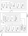
- FIG. 1 is a block diagram illustrating a communication system 100 in accordance with one or more embodiments of this disclosure.
- the communication system 100 includes one or more platforms 102a-b with each platform configurable to transmit and/or receive a signal.
- the one or more platforms 102a-b may be mobile platforms, nonmobile platforms, or any structure upon which an antenna may be disposed.
- the one or more platforms 102a-b may be configured as any type of vehicle including but not limited to aircraft, troop transport vehicles (e.g., jeeps), trailers, tanks, automobiles and artillery.
- the one or more platforms 102a-b may be configured as a backpack.
- the one or more platforms 102a-b may be configured as a radio housing.
- the one or more platforms may be configured as a forward operating base (FOB).
- the communication system 100 may also include or more nodes in an ad hoc network (e.g., a mobile ad hoc network)
- the communication system 100 includes one or more antennas 104a-c disposed on the one or more platforms102a-b.
- the one or more platforms 102a-c may include any number of the one or more antennas 104a-c.
- the one or platforms 102a-b may have a single antenna, two antennas, or ten antennas.
- the one or more antennas 104a-c may be any type of antenna known including but not limited to whip antennas, dipole antennas, isotropic antennas, monopole antennas, array antennas (i.e., one or more elements of an array antenna), loop antennas, conical antennas, aperture antennas, Y-shaped antennas, C-shaped antennas, bent antennas, straight antennas.
- the one or more antennas 104a-c may be a 15-foot whip antenna.
- One or more of the one or more platforms 102a-b may include antennas of different types.
- the one or more platforms102a-b include a transmitter 108a-b and/or receiver 112a-b configured to transmit and/or receive signals and disposed in a radio unit 116a-b.
- the transmitter 108a-b and receiver 112a-b may be combined to form a transceiver.
- the radio unit 116a-b further includes radio circuitry 120a-b configured to process signals received or to be transmitted by the radio unit 116 a-b.
- the radio circuitry may contain any number or type processing circuits (e.g., integrated circuits, FPGA, or wiring boards) to process radio signals.
- the communication system 100 may include one or more control modules 124 communicatively coupled to the one or more radio units 116a-b and configured to control the input and/or output of at least one of the one or more antennas 104a-c of the system.
- the communication system 100 include any number of control modules 124.
- the communication system 100 may include a single control module 124 disposed on one of the one or more platforms 102a-b (i.e., acting as a master control module among the servant one or more antennas 104a-c).
- all of the one or more platforms 102a-b include a control module 124 (i.e., each control module having an ability to control the input and/or output of one or more antennas 124a-c in the communication system.
- some of the platforms 102a-b include a control module 124.
- the control module 124 may be configured as a stand-alone module within the one or more platforms 102a-b or may be integrated into one or more components of the platform 102a-b.
- the control module 124 may be incorporated within a housing of the radio unit 116a-b, where it is communicatively coupled to, or is incorporated with, the radio circuitry 120a-b.
- the control module may operate automatically or may be operated manually via a user interface.
- the control module 124 includes one or more controllers 130 communicatively coupled to other components within the control module 124 and/or one or more platforms 102a-b.
- the one or more controllers 130 may include one or more processors 134, memory 138, and a communication interface 142.
- the memory 138 may store (e.g., have stored upon) one or more sets of program instructions.
- the one or more processors 134 may be configured to execute the one or more sets of program instructions to carry out one or more of the various steps described throughout the present disclosure.
- the one or more processor 134 may be instructed to receive an input.
- the one or more processors 134 may be instructed to receive antenna attribute data (e.g., such as antenna position data).
- the one or more processors 134 may be instructed to determine a compatibility of at least one antenna (104a-c) of the antennas104a-c in the communication system 100 (i.e., of a plurality of antennas 104a-c) for at least one of diversity processing, adaptive antenna processing, or relay processing based on the antenna attribute data. In another example, the one or more processors 134 may be instructed to instruct the controller 130 to configure the communication system 100 for at least one of diversity signal processing, adaptive antenna processing, or relay communication processing based on the compatibility.
- one or more platforms 102a-b includes an antenna attribute unit 146 communicatively coupled to the control module and the one or more radio units 116a-b, and configured to gather antenna attribute data.
- the antenna attribute unit 146 may be configured as a stand-alone unit or may be incorporated within one or more components of the platform 102a-b.
- the antenna attribute unit 146 may be incorporated within the circuitry of the control module.
- the antenna attribute unit may be incorporated within the radio circuitry 120a-b of the one or more radio units 116a-b.
- the communication system 100 includes one or more phase adjusters 150 communicatively coupled to the one or more radio units 116a-b and/or control module 124 and configured to adjust input and/or output from the one or more antennas 104.
- the one or more phase adjusters may be configured to transform a plurality of antenna into a phased-array type antenna.
- the phase adjustments may be coordinated in time with each antenna signal being injected in a particular time by a traffic master, such as the one or more radio units 116a-b.
- the timing of phase adjustments may be based on the antenna attribute data (e.g., relative distances between antennas, antenna shapes, antenna sized, or antenna orientations).
- the one or more phase adjusters 150 may be configured as digital modem processors.
- the one or more phase adjusters 150 may be embodied in hardware circuitry or electronic control circuits that can adjust radiated transmissions.
- the one or more phase adjusters 150 may be operable in a variety of modulation techniques (e.g., amplitude modulation or frequency modulation).
- the individual radio units 116a-b may then receive and/or transmit the phase adjusted signal.
- Conventional HF radio circuits in accordance with principles of the present invention can be utilized.
- the one or more radio units 116a-b and other componentry of the communication system 100 may be configured to adjust the transmit power via the radio circuitry 120a-b.
- the local bearer may be a service that supports low latency/high data rate transmission of signals.
- the local bearer 152 may be configured to support a variety of signal processing techniques including but not limited to diversity signal processing and adaptive antenna processing.
- the local bearer 152 may be configured to support diversity signal processing techniques that include but are not limited to transmit diversity, receive diversity, or diversity combining.
- the local bearer may 152 be configured to support adaptive processing techniques that include but are not limited to beamforming and nulling.
- the one or more controllers 130 are communicatively coupled to other componentry within the control module 124, one or more radio units 116a-b, and or one or more platforms 102a-b within the communication system 100.
- one or more of the one or more controllers 130 may be communicatively coupled to the one or more radio units 116a-b, the phase adjuster 150, the one or more platforms 102a-b, and/or the antenna attribute unit 150.
- the one or more controllers 130 may also be communicatively coupled to other componentry within the communication system 100 not listed here. Therefore, the above description should not be interpreted as a limitation of the present disclosure, but as an illustration.
- the memory 138 may be housed in a common controller housing with the one or more processors 134.
- the memory 138 may, alternatively or in addition, be located remotely with respect to the spatial location of the processors 134, or the one or more controllers 130.
- the one or more processors 134 and/or one or more controllers 130 may access a remote memory 138 accessible through a network (e.g., wireless, and the like) via one or more communication interfaces 142.
- the one or more communication interfaces 142 may be operatively configured to communicate with components of the one or more controllers 130 or any other componentry within the communication system 100.
- the one or more communication interfaces 142 may be configured to retrieve data from the one or more processors 134 or other devices, transmit data for storage in the memory 138, retrieve data from storage in the memory 138, and so forth.
- the one or more communication interfaces 142 may also be communicatively coupled with the one or more processors 134 to facilitate data transfer between components of the one or more controllers 130 and the one or more processors 134.
- one or more communication interfaces 142 is described as a component of the one or more controllers 130, one or more components of the one or more communication interfaces 142 may be implemented as external components communicatively coupled to the one or more controllers 130 via a wired and/or wireless connection.
- the one or more controllers 130 may also include and/or connect to one or more user interfaces.
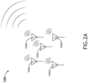
- one or more antennas 104a-e of the plurality of antennas may be organized via the control module 124 to perform beamforming operations (e.g., as shown in FIG. 2A ).
- Beamforming coherently combines radio signals based on direction and provides gain in a desired direction.
- the phase relationship of the signal at each antenna element is manipulated so that the signal emitted by each element in the array combines constructively in the desired direction, resulting in a gain in that direction that is proportional to the number of elements in the array (e.g., as shown in FIG. 2A ).
- the same principal can be used to obtain gain with respect to signals received from a desired direction, with the resulting coherently combined receive signal benefitting from a gain relative to an isotropic noise environment.
- the organization and collaboration of the one or more antennas 104a-e is controlled by the control module 124, or multiple control modules 124 acting in concert with each other.
- the one or more antennas 104a-e of the plurality of antennas may be organized via the control module 124 to perform interference nulling, an adaptive antenna operation that involves nulling the radio signal in a particular direction.
- an array with N antennas 104a-e may form N-1 directional nulls - directions from which signal is effectively cancelled.
- Interference nulling may be applied to both transmit and receive functions. On receive, interference nulling is useful in cancelling out interference impinging upon the one or more antennas 104a-e from specific directions. On transmit, interference nulling may be useful in preventing the emitted signal from propagating in an unwanted direction, either as a source of interference to another receiver, or to prevent an adversary from hearing a transmission.
- the organization and collaboration of the one or more antennas 104a-e is controlled by the control module 124, or multiple control modules 124 acting in concert with each other.
- Many adaptive antenna methods such as nulling require real time exchange of signal information between platforms 104a-e that may be adequately supported through the low latency/high data rate local bearer 152.
- Beamforming and interference nulling techniques are best performed when the plurality of antennas 104a-c are closely spaced, as the techniques perform best with a low latency/high data rate local bearer 152.
- array elements i.e., antennas 104a-e
- beamforming and nulling operations become less practical. Feasible distances are measured in terms of the wavelength of the emitted signal and the minimum separation between individual antennas 104a-e should be on the order of a wavelength or less (ideally 1 ⁇ 2 wavelength for some simple geometries).
- Separation between antennas 104a-e may be determined using the antenna attribute unit 146, precision location technologies or, in some cases, by analysis of the coherence of the signals received by different antennas 104a-e of the plurality of antennas 104a-e.
- the one or more antennas 104a-e of the plurality of antennas 104a-e may be organized via the control module 124 to provide diversity reception and/or transmission. For example, if the minimum antenna separation becomes too great for beamforming and/or nulling, the control module 124 may act to organize one or more antennas 104a-e to provide a diversity gain (e.g., as shown in FIG. 2B ) For instance, the control module 124 may act to organize one or more antennas 104a-e to provide a diversity gain in a fading channel.
- These communications are supported via the local bearer 152, as these techniques require real time exchange of signal information or information derived from the signal (e.g., soft decisions) between each platform 102a-e.
- Fading channels exhibit time-varying variability with respect to receive signal amplitude and phase.
- the received radio signal level can plummet, resulting in bursts of errors when the signal to noise ratio drops below the threshold where errors occur.
- the fading channels when antennas 104a-e are separated by many wavelengths (e.g., 10 or more as a rule of thumb), the fading in the received signals seen at each of the antennas 104a-e is decorrelated. When these radio signals are processed together in a diversity combiner, very significant gains can be achieved.
- a receiver capable of benefitting from multipath and able to resolve the fading paths from each of the transmit antennas 104a-e can obtain a transmit diversity gain.
- the organization and collaboration of the one or more antennas 104a-e is controlled by the control module 124, or multiple control modules 124 acting in concert with each other.
- the concerted action of the multiple control modules 124 may require communication between the multiple control modules 124.
- communication between control modules 124 may be embodied through control signals that are sent and received via the one or more antennas 104a-c.
- communication between control modules 124 may be embodied via non-antenna signaling.
- one or more control modules 124 may send an/or receive instructions via a server 200.
- the one or more control modules 124 may receive instructions in the form of a preloaded lookup table or user input.
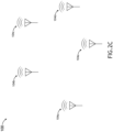
- the one or more antennas 104a-e of the plurality of antennas may be organized via the control module 124 to provide diversity based-relay transmission and/or reception (e.g., as shown in FIG. 2C ).
- the local nodes can fall back upon an "avalanche" relay operation, where each node that hears a transmission retransmits the same information in a subsequent synchronized data slot (i.e., relay receive diversity and relay transmit diversity).
- Avalanche relays are well described in United States patent No. #4,639,937 entitled "HF Avalanche Relay Communication Technique” filed on December 7, 1983 by McRae and Cain .
- the communication system 100 is configured to support at least two of adaptive antenna processing (e.g., beamforming and/or nulling via the local bearer 152), diversity signal processing (e.g., transmit diversity, receive diversity, and/or diversity combining via the local bearer 152), and relay communication processing (e.g., relay transmit diversity and relay receive diversity via long range communication techniques, such as RF).
- adaptive antenna processing e.g., beamforming and/or nulling via the local bearer 152
- diversity signal processing e.g., transmit diversity, receive diversity, and/or diversity combining via the local bearer 152
- relay communication processing e.g., relay transmit diversity and relay receive diversity via long range communication techniques, such as RF.
- the communication system 100 may be synchronously configurable to multiple communication methods (e.g., more than one method at the same time, or more than one method sequentially).
- the communication system 100 may be configured for beamforming when the one or more platforms 102a-b are close to each other (i.e., the one or more antennas 104a-e are close to each other), then reorganize via the control module 124 to be configured for diversity transmission when the one or more platforms 102a-b move away from each other.
- the communication system 100 may be initially configured for diversity transmission, then 100 reorganize via the control module 124 to be configured for relay transmit diversity.
- the communication system 100 may be initially configured for relay transmit diversity, then 100 reorganize via the control module 124 to be configured for beamforming (i.e., when the platforms move in close to each other.
- the communication system 100 is configured to support adaptive antenna processing, diversity signal processing, and relay communication processing (i.e., all methods are supported).
- the different modes of operation may be combined.
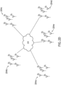
- clusters 204a-e of nodes employing one or more antennas 104a-e that are in close proximity can support adaptive antenna processing via a local bearer to exchange signal (i.e., antennas 104a-e within the same cluster 204a-e performing adaptive antenna processing).
- a local bearer to exchange signal i.e., antennas 104a-e within the same cluster 204a-e performing adaptive antenna processing.
- each cluster 204a-e can independently employ adaptive antenna processing with the resulting signal from each cluster 204a-e processed to obtain further gain from a diversity signal processing (e.g., diversity combining).
- the communication system 100 may gain the benefit of relay receive diversity from multiple platforms 102a-e hearing the original transmission, which then manifests as relay transmit diversity when multiple nodes retransmit the same information via the one or more antennas 104a-e in the subsequent slot.
- Avalanche Relay does not require any coordination between nodes or knowledge of topology or geographic location, this mode of operation is supportable without requiring the exchange of information over a local bearer
- FIG. 2D illustrates a communication system 100 that includes clusters 204a-e of antennas 104a-e, in accordance with one or more embodiments of this disclosure.
- Adaptive antenna processing is supported between platforms 104a, 104b within each cluster 204a-e (via the local bearer 152). as well as diversity signal processing (i.e., the antennas 104a-2 within each cluster 204a-e are spaced closely enough for beamforming or nulling, with each cluster 204a-e as a collaborating whole coordinating with other clusters 204a-e to provide transmit or receive diversity).
- each cluster 204a-e may coordinate locally to provide diversity combining or adaptive antenna operation while still operating as a single transmitter and/or receiver with relay communication processing capability (e.g., avalanche relay operation, which relies mainly on pre-planning for coordination) occurring between the isolated clusters 204a-e (e.g., as shown in FIG. 2E ).
- relay communication processing capability e.g., avalanche relay operation, which relies mainly on pre-planning for coordination
- Platforms 104a-e within the communication system 100 that are not connected by the local bearer 152 may utilize avalanche relay, whether the platform 104-a-e is a solitary node or geographically organized within a cluster 204a-e.
- isolated clusters 204a-e may each have any number of antennas.
- isolated cluster 204a may include one antenna
- isolated cluster 204b may include three antennas
- isolated cluster 204c may include six antennas. Therefore, the above description should not be interpreted as a limitation of the present disclosure, but as an illustration.
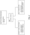
- FIG. 3 illustrates the relationship between the control module 124 and the different transmission/reception methods, in accordance with one or more embodiments of this disclosure.
- the one or more control module 124 are configured to determine, via the one or more processors 134, the available methods of communication to that could utilized within the communication system 100 (e.g., adaptive antenna processing, diversity signal processing, and relay communication processing).
- the one or more control modules 124 may then facilitate the participation of the one or more platforms 102a-b (via the one or more antennas 104a-e, the one or more radio units 116a-b, the one or more antenna attribute units 146, the one or more phase adjusters, and other control modules 124) in the one or more transmission/reception methods described above.
- the communication system 100 may use or be compatible with any type of channel access method including but not limited to frequency division multiple access (FDMA), time division multiple access (TDMA), code division multiple access (CDMA), space division multiple access (SDMA) power division multiple access (PDMA), packet mode methods, duplexing methods, and hybrid channel access scheme application (e.g., Bluetooth).
- FDMA frequency division multiple access
- TDMA time division multiple access
- CDMA code division multiple access
- SDMA space division multiple access
- PDMA power division multiple access
- packet mode methods e.g., Bluetooth
- hybrid channel access scheme application e.g., Bluetooth
- the communication system 100 may also use or be compatible with any type of diversity reception/transmission methods including but not limited to timing combining, transmit/reception diversity, antenna diversity, cooperative diversity, and smart antenna technology. Therefore, the above description should not be interpreted as a limitation of the present disclosure, but as an illustration.
- FIG. 4 is a flow diagram illustrating a method 400 for radio communication, in accordance with one or more embodiments of this disclosure.
- the method includes a step 402 of receiving antenna attribute data from a plurality of antennas of a communication system, wherein the plurality of antennas is disposed on at least two platforms.
- the one or more processors 134 of the control module 124 may receive antenna attribute data that includes positional data of several antennas 104a-e via the antenna attribute unit 146.
- the method includes a step 404 of determining if a least one of the plurality of antennas are configurable for at least one of diversity signal processing, adaptive antenna processing, or relay communication processing. In some embodiments, the method includes a step 406 of instructing the controller to configure the communication system for at least one of diversity signal processing, adaptive antenna processing, or relay processing based on the determination (e.g., the determination made by the control module 124 based on the antenna attribute data).
- embodiments of the methods disclosed herein may include one or more of the steps described herein. Further, such steps may be carried out in any desired order and two or more of the steps may be carried out simultaneously with one another. Two or more of the steps disclosed herein may be combined in a single step, and in some embodiments, one or more of the steps may be carried out as two or more sub-steps. Further, other steps or sub-steps may be carried in addition to, or as substitutes to one or more of the steps disclosed herein.
Landscapes
- Engineering & Computer Science (AREA)
- Signal Processing (AREA)
- Computer Networks & Wireless Communication (AREA)
- Power Engineering (AREA)
- Mobile Radio Communication Systems (AREA)
- Radio Transmission System (AREA)
Claims (7)
- Kommunikationssystem, umfassend:eine Vielzahl von Antennen (104a-c), die auf zwei oder mehr Plattformen (102a-b) eines Netzwerks angeordnet ist, wobei die zwei oder mehr Plattformen physisch getrennt und unabhängig voneinander mobil sind;mindestens einen Sender (108a-b), der auf jeder der zwei oder mehr Plattformen angeordnet ist und kommunikativ mit mindestens einer Antenne der Vielzahl von Antennen (104a-c) gekoppelt ist;mindestens einen Empfänger (112a-b), der auf jeder der zwei oder mehr Plattformen angeordnet ist und kommunikativ mit der mindestens einen Antenne der Vielzahl von Antennen gekoppelt ist; undmindestens ein Steuermodul (124), das kommunikativ mit dem mindestens einen Sender (108a-b) und dem mindestens einen Empfänger (112a-b) gekoppelt ist und auf einer anderen Plattform angeordnet ist als eine der mindestens einen Antenne der Vielzahl von Antennen (104a-c), wobei das mindestens eine Steuermodul (124) dazu konfiguriert ist, Empfangssignale, die durch den mindestens einen Empfänger empfangen werden, und Sendesignale, die durch den mindestens einen Sender gesendet werden, zu steuern, wobei das mindestens eine Steuermodul Folgendes umfasst:eine Steuereinheit (130);einen oder mehrere Prozessoren (134), die kommunikativ mit der Steuereinheit (130) gekoppelt sind; undeinen Speicher (138), der kommunikativ mit dem einen oder den mehreren Prozessoren (134) gekoppelt ist und auf dem Anweisungen gespeichert sind, die, wenn sie von dem einen oder den mehreren Prozessoren ausgeführt werden, den einen oder die mehreren Prozessoren dazu veranlassen, Folgendes zu tun:Empfangen von Antennenattributdaten;Bestimmen einer Kompatibilität von mindestens einer Antenne der Vielzahl von Antennen für die Relaiskommunikationsverarbeitung und mindestens einer von der Diversitätssignalverarbeitung oder der adaptiven Antennenverarbeitung basierend auf den Antennenattributdaten, wobei die Antennenattributdaten einen Abstand zwischen der mindestens einen Antenne und einer anderen Antenne auf einer anderen Plattform beinhalten;Anweisen der Steuereinheit, das Kommunikationssystem für die Relaiskommunikationsverarbeitung oder mindestens eine von der Diversitätssignalverarbeitung oder der adaptiven Antennenverarbeitung basierend auf der Kompatibilität zu konfigurieren;wobei die Diversitätssignalverarbeitung mindestens eines von Sendediversität, Empfangsdiversität oder Diversitätskombination umfasst;wobei die adaptive Antennenverarbeitung mindestens eines von Strahlformung und Nullung umfasst;wobei die Relais-Kommunikationsverarbeitung ein Avalanche-Relais umfasst.
- System nach Anspruch 1, wobei das System für zwei oder mehr von der Relaiskommunikationsverarbeitung, Diversitätssignalverarbeitung oder adaptiven Antennenverarbeitung konfiguriert ist.
- System nach Anspruch 1 oder 2, wobei das System für zwei oder mehr der folgenden Verarbeitungsarten synchron konfiguriert ist: Diversitätssignalverarbeitung, adaptive Antennenverarbeitung oder Relaiskommunikationsverarbeitung.
- System nach einem der vorhergehenden Ansprüche, ferner umfassend einen oder mehrere Phaseneinsteller (150), wobei das mindestens eine Steuermodul (124) dazu konfiguriert ist, die Phaseneinsteller entsprechend einem Abstand zwischen zwei oder mehreren Antennen der Vielzahl von Antennen einzustellen.
- System gemäß einem der vorhergehenden Ansprüche, wobei das System mindestens einen Knoten in einem Ad-hoc-Netzwerk umfasst.
- System gemäß einem der vorhergehenden Ansprüche, das außerdem eine Antennenattributeinheit (146) umfasst, die dazu konfiguriert ist, mindestens ein Attribut der Antennenattributdaten zu bestimmen.
- Verfahren, gekennzeichnet durch:Empfangen von Antennenattributdaten von einer Vielzahl von Antennen eines Kommunikationssystems, wobei die Vielzahl von Antennen auf mindestens zwei Plattformen eines Netzwerks angeordnet ist, wobei die zwei oder mehr Plattformen physisch getrennt und unabhängig voneinander mobil sind, wobei auf jeder der zwei oder mehr Plattformen mindestens ein Sender angeordnet ist, der kommunikativ mit mindestens einer Antenne der Vielzahl von Antennen gekoppelt ist, auf jeder der zwei oder mehr Plattformen mindestens ein Empfänger angeordnet ist, der kommunikativ mit der mindestens einen Antenne der Vielzahl von Antennen gekoppelt ist, und wobei die Antennenattributdaten einen Abstand zwischen der mindestens einen Antenne und einer anderen Antenne auf einer anderen Plattform umfassen;Bestimmen einer Kompatibilität von mindestens einer Antenne der Vielzahl von Antennen für die Relaiskommunikationsverarbeitung und mindestens einer von der Diversitätssignalverarbeitung oder der adaptiven Antennenverarbeitung; undAnweisen der Steuereinheit, das Kommunikationssystem für die Relaiskommunikationsverarbeitung oder mindestens eine von der Diversitätssignalverarbeitung oder der adaptiven Antennenverarbeitung basierend auf der Kompatibilität zu konfigurieren;wobei die Diversitätssignalverarbeitung mindestens eines von Sendediversität, Empfangsdiversität oder Diversitätskombination umfasst;wobei die adaptive Antennenverarbeitung mindestens eines von Strahlformung und Nullung umfasst;wobei die Relais-Kommunikationsverarbeitung ein Avalanche-Relais umfasst.
Applications Claiming Priority (1)
| Application Number | Priority Date | Filing Date | Title |
|---|---|---|---|
| US17/139,362 US11411613B2 (en) | 2020-12-31 | 2020-12-31 | Adaptation of coordinated radio frequency transmissions and receptions |
Publications (2)
| Publication Number | Publication Date |
|---|---|
| EP4024725A1 EP4024725A1 (de) | 2022-07-06 |
| EP4024725B1 true EP4024725B1 (de) | 2024-10-09 |
Family
ID=79024904
Family Applications (1)
| Application Number | Title | Priority Date | Filing Date |
|---|---|---|---|
| EP21218114.3A Active EP4024725B1 (de) | 2020-12-31 | 2021-12-29 | Anpassung von koordinierten hochfrequenzübertragungen und -empfängen |
Country Status (2)
| Country | Link |
|---|---|
| US (1) | US11411613B2 (de) |
| EP (1) | EP4024725B1 (de) |
Families Citing this family (17)
| Publication number | Priority date | Publication date | Assignee | Title |
|---|---|---|---|---|
| US12553978B2 (en) | 2019-11-27 | 2026-02-17 | Rockwell Collins, Inc. | Proactive link acquisition (spatial awareness) |
| US11977173B2 (en) | 2019-11-27 | 2024-05-07 | Rockwell Collins, Inc. | Spoofing and denial of service detection and protection with doppler nulling (spatial awareness) |
| US12050279B2 (en) | 2019-11-27 | 2024-07-30 | Rockwell Collins, Inc. | Doppler nulling spatial awareness (DNSA) solutions for non-terrestrial networks |
| US12540997B2 (en) | 2019-11-27 | 2026-02-03 | Rockwell Collins, Inc. | System and method for application of doppler null scanning (DNS) to position navigation timing (PNT) |
| US12153150B2 (en) | 2019-11-27 | 2024-11-26 | Rockwell Collins, Inc. | Doppler nulling scanning (DNS) security (spatial awareness) |
| US12111406B2 (en) | 2019-11-27 | 2024-10-08 | Rockwell Collins, Inc. | Adaptive doppler-nulling digitization for high-resolution |
| US12498442B2 (en) | 2019-11-27 | 2025-12-16 | Rockwell Collins, Inc. | Robust addressing schema for spatial awareness via doppler null scanning (DNS) |
| US12326506B2 (en) | 2019-11-27 | 2025-06-10 | Rockwell Collins, Inc. | DNS spatial discoveries with on-going traffic |
| US12137048B2 (en) | 2019-11-27 | 2024-11-05 | Rockwell Collins, Inc. | System and method for spatial awareness network routing |
| US12584986B2 (en) | 2019-11-27 | 2026-03-24 | Rockwell Collins, Inc. | Reliable efficient flooding with Doppler nulling (spatial awareness) |
| US12474431B2 (en) | 2019-11-27 | 2025-11-18 | Rockwell Collins, Inc. | Doppler-nulling and two-way timing and ranging (spatial awareness) |
| US12504496B2 (en) | 2019-11-27 | 2025-12-23 | Rockwell Collins, Inc. | Station keeping using doppler null scanning |
| US12523733B2 (en) | 2019-11-27 | 2026-01-13 | Rockwell Collins, Inc | Directional enhancements for mobile ad hoc networks (MANET) via doppler null scanning (DNS) |
| US12546845B2 (en) | 2021-11-23 | 2026-02-10 | Rockwell Collins, Inc. | Search and rescue system with doppler-nulling spatial awareness |
| US12571868B2 (en) | 2019-11-27 | 2026-03-10 | Rockwell Collins, Inc. | Doppler null scanning for coordination including expendable platforms (spatial awareness) |
| US12432794B1 (en) | 2023-02-02 | 2025-09-30 | Rockwell Collins, Inc. | Avalanche relay linking system |
| US12328149B1 (en) * | 2023-02-02 | 2025-06-10 | Rockwell Collins, Inc. | Notification system and apparatus |
Family Cites Families (16)
| Publication number | Priority date | Publication date | Assignee | Title |
|---|---|---|---|---|
| US4639937A (en) | 1983-12-07 | 1987-01-27 | Harris Corporation | HF avalanche relay communication technique |
| US7382315B1 (en) | 2003-03-11 | 2008-06-03 | Rockwell Collins, Inc. | System for and method of improving beyond line-of-sight transmissions and receptions |
| US7764655B2 (en) | 2003-03-31 | 2010-07-27 | Nextg Networks, Inc. | Local area network utilizing macro and micro diversity techniques in receiving signals from cell sites |
| WO2006121381A1 (en) | 2005-05-06 | 2006-11-16 | Ericsson Ab | Method and arrangement in wireless communication networks using relaying |
| CN100576769C (zh) | 2005-06-07 | 2009-12-30 | 上海贝尔阿尔卡特股份有限公司 | 一种在移动通信网络中用于自适应多天线分集的装置及其方法 |
| US7406060B2 (en) * | 2005-07-06 | 2008-07-29 | Nortel Networks Limited | Coverage improvement in wireless systems with fixed infrastructure based relays |
| ES2380987T3 (es) | 2006-12-14 | 2012-05-22 | Mosaid Technologies Incorporated | Sistema de antena adaptable para diversidad y prevención de interferencias en una red de estaciones múltiples |
| WO2008155764A2 (en) | 2007-06-18 | 2008-12-24 | Duolink Ltd. | Wireless network architecture and method for base station utilization |
| CN101796740A (zh) * | 2007-09-06 | 2010-08-04 | 富士通株式会社 | 使用自适应多天线的移动通信系统 |
| US9681464B2 (en) | 2009-09-18 | 2017-06-13 | Industrial Technology Research Institute | Cooperative transmission within heterogeneous stations |
| US10419533B2 (en) * | 2010-03-01 | 2019-09-17 | Genghiscomm Holdings, LLC | Edge server selection for device-specific network topologies |
| US9780928B2 (en) * | 2011-10-17 | 2017-10-03 | Golba Llc | Method and system for providing diversity in a network that utilizes distributed transceivers and array processing |
| US9705571B2 (en) | 2015-09-16 | 2017-07-11 | At&T Intellectual Property I, L.P. | Method and apparatus for use with a radio distributed antenna system |
| US11411615B2 (en) * | 2018-03-29 | 2022-08-09 | Qualcomm Incorporated | Enhanced antenna utilization |
| JP2019205131A (ja) * | 2018-05-25 | 2019-11-28 | シャープ株式会社 | 制御装置、電子機器、及び制御方法 |
| US11147060B2 (en) | 2018-11-28 | 2021-10-12 | Qualcomm Incorporated | Management of multiple antenna panels |
-
2020
- 2020-12-31 US US17/139,362 patent/US11411613B2/en active Active
-
2021
- 2021-12-29 EP EP21218114.3A patent/EP4024725B1/de active Active
Also Published As
| Publication number | Publication date |
|---|---|
| EP4024725A1 (de) | 2022-07-06 |
| US11411613B2 (en) | 2022-08-09 |
| US20220209826A1 (en) | 2022-06-30 |
Similar Documents
| Publication | Publication Date | Title |
|---|---|---|
| EP4024725B1 (de) | Anpassung von koordinierten hochfrequenzübertragungen und -empfängen | |
| US11012136B2 (en) | Beamforming in a MU-MIMO wireless communication system with relays | |
| US6642887B2 (en) | Cooperative mobile antenna system | |
| US8831164B2 (en) | Method and apparatus for cooperative communications between groups of communication units using a time reversed channel response | |
| US7777674B1 (en) | Mobile distributed antenna array for wireless communication | |
| US8320825B2 (en) | Method and apparatus for repeating a signal in a wireless communication system | |
| US20020042290A1 (en) | Method and apparatus employing a remote wireless repeater for calibrating a wireless base station having an adaptive antenna array | |
| EP1191706A3 (de) | Verfahren zur Abwärtsrichtungsstrahlformung in FDD drahtlosen Kommunikationssystemen | |
| EP3314775B1 (de) | Verfahren und vorrichtung zur drahtlosen kommunikation | |
| JP4019767B2 (ja) | 単一周波数ネットワークシステムおよび中継器 | |
| WO2022011510A1 (zh) | 一种通信方法、通信装置及存储介质 | |
| US8515493B1 (en) | Antenna array formed by a network of transceivers | |
| KR102128400B1 (ko) | 무선전송 장치의 전파 빔 방향 조정 방법 | |
| JP2001275150A (ja) | 無線基地局 | |
| CA3049772A1 (en) | Real time adaptation of a mobile repeater antenna pattern | |
| KR102101514B1 (ko) | 다중 빔 송신 장치 및 이를 이용한 다중 빔 전송 방법 | |
| US12328642B2 (en) | System and method for coordinated beamforming among discrete communication devices | |
| Zhang et al. | Optimizing Full-Duplex Multi-Hop UAV Networks: A Joint Approach for Positioning and Beamforming | |
| US5990832A (en) | Antenna array for base station for radiocommunication with mobiles | |
| Spyropoulos et al. | ADAPT: a media access control protocol for mobile ad hoc networks using adaptive array antennas | |
| US11777570B2 (en) | Simultaneous beamforming and nullforming for secure wireless communications | |
| Abualhauja'a et al. | RIS‐Assisted UAV Communications | |
| CN121970268A (zh) | 控制装置、无线通信系统、以及控制方法 | |
| Uda et al. | Adaptive Antenna Selection for Two-Hop Full-Duplex UAV Relay Networks | |
| JPH11298225A (ja) | 基地局アンテナ装置 |
Legal Events
| Date | Code | Title | Description |
|---|---|---|---|
| PUAI | Public reference made under article 153(3) epc to a published international application that has entered the european phase |
Free format text: ORIGINAL CODE: 0009012 |
|
| STAA | Information on the status of an ep patent application or granted ep patent |
Free format text: STATUS: THE APPLICATION HAS BEEN PUBLISHED |
|
| AK | Designated contracting states |
Kind code of ref document: A1 Designated state(s): AL AT BE BG CH CY CZ DE DK EE ES FI FR GB GR HR HU IE IS IT LI LT LU LV MC MK MT NL NO PL PT RO RS SE SI SK SM TR |
|
| STAA | Information on the status of an ep patent application or granted ep patent |
Free format text: STATUS: REQUEST FOR EXAMINATION WAS MADE |
|
| 17P | Request for examination filed |
Effective date: 20221228 |
|
| RBV | Designated contracting states (corrected) |
Designated state(s): AL AT BE BG CH CY CZ DE DK EE ES FI FR GB GR HR HU IE IS IT LI LT LU LV MC MK MT NL NO PL PT RO RS SE SI SK SM TR |
|
| GRAP | Despatch of communication of intention to grant a patent |
Free format text: ORIGINAL CODE: EPIDOSNIGR1 |
|
| STAA | Information on the status of an ep patent application or granted ep patent |
Free format text: STATUS: GRANT OF PATENT IS INTENDED |
|
| RIC1 | Information provided on ipc code assigned before grant |
Ipc: H04L 1/00 20060101ALN20240412BHEP Ipc: H04B 7/026 20170101ALN20240412BHEP Ipc: H04B 7/06 20060101AFI20240412BHEP |
|
| INTG | Intention to grant announced |
Effective date: 20240521 |
|
| GRAS | Grant fee paid |
Free format text: ORIGINAL CODE: EPIDOSNIGR3 |
|
| GRAA | (expected) grant |
Free format text: ORIGINAL CODE: 0009210 |
|
| STAA | Information on the status of an ep patent application or granted ep patent |
Free format text: STATUS: THE PATENT HAS BEEN GRANTED |
|
| AK | Designated contracting states |
Kind code of ref document: B1 Designated state(s): AL AT BE BG CH CY CZ DE DK EE ES FI FR GB GR HR HU IE IS IT LI LT LU LV MC MK MT NL NO PL PT RO RS SE SI SK SM TR |
|
| REG | Reference to a national code |
Ref country code: CH Ref legal event code: EP |
|
| REG | Reference to a national code |
Ref country code: DE Ref legal event code: R096 Ref document number: 602021019905 Country of ref document: DE |
|
| REG | Reference to a national code |
Ref country code: IE Ref legal event code: FG4D |
|
| REG | Reference to a national code |
Ref country code: LT Ref legal event code: MG9D |
|
| REG | Reference to a national code |
Ref country code: NL Ref legal event code: MP Effective date: 20241009 |
|
| REG | Reference to a national code |
Ref country code: AT Ref legal event code: MK05 Ref document number: 1731719 Country of ref document: AT Kind code of ref document: T Effective date: 20241009 |
|
| PG25 | Lapsed in a contracting state [announced via postgrant information from national office to epo] |
Ref country code: NL Free format text: LAPSE BECAUSE OF FAILURE TO SUBMIT A TRANSLATION OF THE DESCRIPTION OR TO PAY THE FEE WITHIN THE PRESCRIBED TIME-LIMIT Effective date: 20241009 |
|
| PG25 | Lapsed in a contracting state [announced via postgrant information from national office to epo] |
Ref country code: NL Free format text: LAPSE BECAUSE OF FAILURE TO SUBMIT A TRANSLATION OF THE DESCRIPTION OR TO PAY THE FEE WITHIN THE PRESCRIBED TIME-LIMIT Effective date: 20241009 |
|
| PG25 | Lapsed in a contracting state [announced via postgrant information from national office to epo] |
Ref country code: PT Free format text: LAPSE BECAUSE OF FAILURE TO SUBMIT A TRANSLATION OF THE DESCRIPTION OR TO PAY THE FEE WITHIN THE PRESCRIBED TIME-LIMIT Effective date: 20250210 Ref country code: IS Free format text: LAPSE BECAUSE OF FAILURE TO SUBMIT A TRANSLATION OF THE DESCRIPTION OR TO PAY THE FEE WITHIN THE PRESCRIBED TIME-LIMIT Effective date: 20250209 Ref country code: HR Free format text: LAPSE BECAUSE OF FAILURE TO SUBMIT A TRANSLATION OF THE DESCRIPTION OR TO PAY THE FEE WITHIN THE PRESCRIBED TIME-LIMIT Effective date: 20241009 |
|
| PG25 | Lapsed in a contracting state [announced via postgrant information from national office to epo] |
Ref country code: FI Free format text: LAPSE BECAUSE OF FAILURE TO SUBMIT A TRANSLATION OF THE DESCRIPTION OR TO PAY THE FEE WITHIN THE PRESCRIBED TIME-LIMIT Effective date: 20241009 |
|
| PG25 | Lapsed in a contracting state [announced via postgrant information from national office to epo] |
Ref country code: BG Free format text: LAPSE BECAUSE OF FAILURE TO SUBMIT A TRANSLATION OF THE DESCRIPTION OR TO PAY THE FEE WITHIN THE PRESCRIBED TIME-LIMIT Effective date: 20241009 |
|
| PG25 | Lapsed in a contracting state [announced via postgrant information from national office to epo] |
Ref country code: ES Free format text: LAPSE BECAUSE OF FAILURE TO SUBMIT A TRANSLATION OF THE DESCRIPTION OR TO PAY THE FEE WITHIN THE PRESCRIBED TIME-LIMIT Effective date: 20241009 |
|
| PG25 | Lapsed in a contracting state [announced via postgrant information from national office to epo] |
Ref country code: NO Free format text: LAPSE BECAUSE OF FAILURE TO SUBMIT A TRANSLATION OF THE DESCRIPTION OR TO PAY THE FEE WITHIN THE PRESCRIBED TIME-LIMIT Effective date: 20250109 |
|
| PG25 | Lapsed in a contracting state [announced via postgrant information from national office to epo] |
Ref country code: LV Free format text: LAPSE BECAUSE OF FAILURE TO SUBMIT A TRANSLATION OF THE DESCRIPTION OR TO PAY THE FEE WITHIN THE PRESCRIBED TIME-LIMIT Effective date: 20241009 Ref country code: GR Free format text: LAPSE BECAUSE OF FAILURE TO SUBMIT A TRANSLATION OF THE DESCRIPTION OR TO PAY THE FEE WITHIN THE PRESCRIBED TIME-LIMIT Effective date: 20250110 Ref country code: AT Free format text: LAPSE BECAUSE OF FAILURE TO SUBMIT A TRANSLATION OF THE DESCRIPTION OR TO PAY THE FEE WITHIN THE PRESCRIBED TIME-LIMIT Effective date: 20241009 |
|
| PG25 | Lapsed in a contracting state [announced via postgrant information from national office to epo] |
Ref country code: PL Free format text: LAPSE BECAUSE OF FAILURE TO SUBMIT A TRANSLATION OF THE DESCRIPTION OR TO PAY THE FEE WITHIN THE PRESCRIBED TIME-LIMIT Effective date: 20241009 |
|
| PG25 | Lapsed in a contracting state [announced via postgrant information from national office to epo] |
Ref country code: RS Free format text: LAPSE BECAUSE OF FAILURE TO SUBMIT A TRANSLATION OF THE DESCRIPTION OR TO PAY THE FEE WITHIN THE PRESCRIBED TIME-LIMIT Effective date: 20250109 |
|
| PG25 | Lapsed in a contracting state [announced via postgrant information from national office to epo] |
Ref country code: SM Free format text: LAPSE BECAUSE OF FAILURE TO SUBMIT A TRANSLATION OF THE DESCRIPTION OR TO PAY THE FEE WITHIN THE PRESCRIBED TIME-LIMIT Effective date: 20241009 |
|
| PG25 | Lapsed in a contracting state [announced via postgrant information from national office to epo] |
Ref country code: MC Free format text: LAPSE BECAUSE OF FAILURE TO SUBMIT A TRANSLATION OF THE DESCRIPTION OR TO PAY THE FEE WITHIN THE PRESCRIBED TIME-LIMIT Effective date: 20241009 |
|
| PG25 | Lapsed in a contracting state [announced via postgrant information from national office to epo] |
Ref country code: DK Free format text: LAPSE BECAUSE OF FAILURE TO SUBMIT A TRANSLATION OF THE DESCRIPTION OR TO PAY THE FEE WITHIN THE PRESCRIBED TIME-LIMIT Effective date: 20241009 |
|
| REG | Reference to a national code |
Ref country code: DE Ref legal event code: R097 Ref document number: 602021019905 Country of ref document: DE |
|
| PG25 | Lapsed in a contracting state [announced via postgrant information from national office to epo] |
Ref country code: EE Free format text: LAPSE BECAUSE OF FAILURE TO SUBMIT A TRANSLATION OF THE DESCRIPTION OR TO PAY THE FEE WITHIN THE PRESCRIBED TIME-LIMIT Effective date: 20241009 |
|
| PG25 | Lapsed in a contracting state [announced via postgrant information from national office to epo] |
Ref country code: RO Free format text: LAPSE BECAUSE OF FAILURE TO SUBMIT A TRANSLATION OF THE DESCRIPTION OR TO PAY THE FEE WITHIN THE PRESCRIBED TIME-LIMIT Effective date: 20241009 |
|
| PG25 | Lapsed in a contracting state [announced via postgrant information from national office to epo] |
Ref country code: SK Free format text: LAPSE BECAUSE OF FAILURE TO SUBMIT A TRANSLATION OF THE DESCRIPTION OR TO PAY THE FEE WITHIN THE PRESCRIBED TIME-LIMIT Effective date: 20241009 |
|
| PG25 | Lapsed in a contracting state [announced via postgrant information from national office to epo] |
Ref country code: CZ Free format text: LAPSE BECAUSE OF FAILURE TO SUBMIT A TRANSLATION OF THE DESCRIPTION OR TO PAY THE FEE WITHIN THE PRESCRIBED TIME-LIMIT Effective date: 20241009 |
|
| PG25 | Lapsed in a contracting state [announced via postgrant information from national office to epo] |
Ref country code: IT Free format text: LAPSE BECAUSE OF FAILURE TO SUBMIT A TRANSLATION OF THE DESCRIPTION OR TO PAY THE FEE WITHIN THE PRESCRIBED TIME-LIMIT Effective date: 20241009 |
|
| REG | Reference to a national code |
Ref country code: CH Ref legal event code: PL |
|
| PLBE | No opposition filed within time limit |
Free format text: ORIGINAL CODE: 0009261 |
|
| STAA | Information on the status of an ep patent application or granted ep patent |
Free format text: STATUS: NO OPPOSITION FILED WITHIN TIME LIMIT |
|
| PG25 | Lapsed in a contracting state [announced via postgrant information from national office to epo] |
Ref country code: LU Free format text: LAPSE BECAUSE OF NON-PAYMENT OF DUE FEES Effective date: 20241229 |
|
| PG25 | Lapsed in a contracting state [announced via postgrant information from national office to epo] |
Ref country code: SE Free format text: LAPSE BECAUSE OF FAILURE TO SUBMIT A TRANSLATION OF THE DESCRIPTION OR TO PAY THE FEE WITHIN THE PRESCRIBED TIME-LIMIT Effective date: 20241009 |
|
| 26N | No opposition filed |
Effective date: 20250710 |
|
| REG | Reference to a national code |
Ref country code: BE Ref legal event code: MM Effective date: 20241231 |
|
| PG25 | Lapsed in a contracting state [announced via postgrant information from national office to epo] |
Ref country code: BE Free format text: LAPSE BECAUSE OF NON-PAYMENT OF DUE FEES Effective date: 20241231 |
|
| PG25 | Lapsed in a contracting state [announced via postgrant information from national office to epo] |
Ref country code: CH Free format text: LAPSE BECAUSE OF NON-PAYMENT OF DUE FEES Effective date: 20241231 |
|
| PG25 | Lapsed in a contracting state [announced via postgrant information from national office to epo] |
Ref country code: IE Free format text: LAPSE BECAUSE OF NON-PAYMENT OF DUE FEES Effective date: 20241229 |
|
| PGFP | Annual fee paid to national office [announced via postgrant information from national office to epo] |
Ref country code: DE Payment date: 20251126 Year of fee payment: 5 |
|
| PGFP | Annual fee paid to national office [announced via postgrant information from national office to epo] |
Ref country code: GB Payment date: 20251119 Year of fee payment: 5 |
|
| PGFP | Annual fee paid to national office [announced via postgrant information from national office to epo] |
Ref country code: FR Payment date: 20251120 Year of fee payment: 5 |