EP4024728A1 - Émetteur, récepteur et procédés permettant de transmettre/recevoir des signaux de synchronisation - Google Patents
Émetteur, récepteur et procédés permettant de transmettre/recevoir des signaux de synchronisation Download PDFInfo
- Publication number
- EP4024728A1 EP4024728A1 EP21211965.5A EP21211965A EP4024728A1 EP 4024728 A1 EP4024728 A1 EP 4024728A1 EP 21211965 A EP21211965 A EP 21211965A EP 4024728 A1 EP4024728 A1 EP 4024728A1
- Authority
- EP
- European Patent Office
- Prior art keywords
- symbols
- type
- synchronisation signal
- subframe
- synchronisation
- Prior art date
- Legal status (The legal status is an assumption and is not a legal conclusion. Google has not performed a legal analysis and makes no representation as to the accuracy of the status listed.)
- Granted
Links
Images






Classifications
-
- H—ELECTRICITY
- H04—ELECTRIC COMMUNICATION TECHNIQUE
- H04W—WIRELESS COMMUNICATION NETWORKS
- H04W56/00—Synchronisation arrangements
- H04W56/001—Synchronization between nodes
- H04W56/002—Mutual synchronization
-
- H—ELECTRICITY
- H04—ELECTRIC COMMUNICATION TECHNIQUE
- H04B—TRANSMISSION
- H04B7/00—Radio transmission systems, i.e. using radiation field
- H04B7/24—Radio transmission systems, i.e. using radiation field for communication between two or more posts
- H04B7/26—Radio transmission systems, i.e. using radiation field for communication between two or more posts at least one of which is mobile
- H04B7/2643—Radio transmission systems, i.e. using radiation field for communication between two or more posts at least one of which is mobile using time-division multiple access [TDMA]
- H04B7/2656—Radio transmission systems, i.e. using radiation field for communication between two or more posts at least one of which is mobile using time-division multiple access [TDMA] for structure of frame, burst
-
- H—ELECTRICITY
- H04—ELECTRIC COMMUNICATION TECHNIQUE
- H04W—WIRELESS COMMUNICATION NETWORKS
- H04W56/00—Synchronisation arrangements
- H04W56/001—Synchronization between nodes
- H04W56/0015—Synchronization between nodes one node acting as a reference for the others
-
- H—ELECTRICITY
- H04—ELECTRIC COMMUNICATION TECHNIQUE
- H04W—WIRELESS COMMUNICATION NETWORKS
- H04W72/00—Local resource management
- H04W72/12—Wireless traffic scheduling
- H04W72/1215—Wireless traffic scheduling for collaboration of different radio technologies
-
- H—ELECTRICITY
- H04—ELECTRIC COMMUNICATION TECHNIQUE
- H04B—TRANSMISSION
- H04B7/00—Radio transmission systems, i.e. using radiation field
- H04B7/24—Radio transmission systems, i.e. using radiation field for communication between two or more posts
- H04B7/26—Radio transmission systems, i.e. using radiation field for communication between two or more posts at least one of which is mobile
- H04B7/2621—Radio transmission systems, i.e. using radiation field for communication between two or more posts at least one of which is mobile using frequency division multiple access [FDMA]
-
- H—ELECTRICITY
- H04—ELECTRIC COMMUNICATION TECHNIQUE
- H04L—TRANSMISSION OF DIGITAL INFORMATION, e.g. TELEGRAPHIC COMMUNICATION
- H04L27/00—Modulated-carrier systems
- H04L27/26—Systems using multi-frequency codes
- H04L27/2601—Multicarrier modulation systems
-
- H—ELECTRICITY
- H04—ELECTRIC COMMUNICATION TECHNIQUE
- H04W—WIRELESS COMMUNICATION NETWORKS
- H04W88/00—Devices specially adapted for wireless communication networks, e.g. terminals, base stations or access point devices
- H04W88/02—Terminal devices
- H04W88/06—Terminal devices adapted for operation in multiple networks or having at least two operational modes, e.g. multi-mode terminals
Definitions
- Implementations described herein generally relate to a transmitter, a method in a transmitter, a receiver and a method in a receiver.
- a mechanism is herein described, for transmitting a first type of synchronisation signal and a second type of synchronisation signal.
- transmitters and receivers In a wireless communication system, transmitters and receivers have to be synchronised in time and frequency in order to communicate. This is typically achieved by letting the transmitter transmit a synchronisation signal which the receiver can detect.
- synchronisation signals are used for cell search, which is the procedure by which the User Equipment (UE) acquires time- and frequency synchronisation with a cell and detects its cell ID.
- the UE may sometimes be referred to as a mobile terminal, wireless terminal, mobile station, mobile telephone, cellular telephone, or similar.
- the wireless communication system covers a geographical area which may be divided into cell areas, with each cell area being served by a radio network node or base station, e.g., a Radio Base Station (RBS) or Base Transceiver Station (BTS), which in some networks may be referred to as "eNB”, “eNodeB”, “NodeB” or “B node”, depending on the technology and/ or terminology used.
- a radio network node or base station e.g., a Radio Base Station (RBS) or Base Transceiver Station (BTS), which in some networks may be referred to as “eNB”, “eNodeB”, “NodeB” or “B node”, depending on the technology and/ or terminology used.
- eNB Radio Base Station
- BTS Base Transceiver Station
- eNB Radio Base Station
- eNodeB NodeB
- B node Base Transceiver Station
- D2D Device-to-Device
- synchronisation signals may be defined; each serving its specific purpose.
- one type of signal may be designed for obtaining timing synchronisation on a sample level, while another type of synchronisation signal, may provide additional information, e.g., for obtaining subframe or radio frame level synchronisation.
- the process of acquiring synchronisation is computationally intense, contributing to the power consumption of the receiver while also constituting a significant part of the cost of its chipset.
- synchronisation signals have to be designed to provide for low-complex implementations in the receiver.
- synchronisation signals may be transmitted in bursts. That is, several synchronisation signals may be transmitted in a short period of time, i.e., a burst while the period of the bursts may be relatively long. This allows the receiver to obtain synchronisation in a relatively short time, i.e., from receiving just one single synchronisation burst.
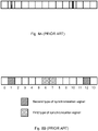
- Figure 8A shows an example where a burst contains several Orthogonal Frequency-Division Multiplexing (OFDM), or alternatively Single Carrier-Frequency Division Multiple Access (SC-FDMA) symbols carrying synchronisation signals, while having a burst period which is long in comparison to the inter-symbol spacing of the synchronisation symbols within the burst.
- OFDM Orthogonal Frequency-Division Multiplexing
- SC-FDMA Single Carrier-Frequency Division Multiple Access
- a direct consequence of a burst transmission is therefore that the distance between OFDM/ SC-FDMA symbols containing a synchronisation signal may not be uniform. This is in contrast to a periodic transmission, wherein the synchronisation signal is transmitted with equidistantly placed OFDM/ SC-FDMA symbols.
- Burst transmission of synchronisation signals may be efficient, e.g., for systems that utilise fast ON/ OFF switching of the cells, to adapt to the dynamically varying traffic loads. Once the cell has been switched ON, receivers may quickly synchronise to it, which makes burst transmission of the synchronisation signal from the cell desirable.
- a further example is Device-to-Device (D2D) communications, where a mobile terminal is transmitting the synchronisation signal, which is to be detected by another mobile terminal in its vicinity.
- D2D Device-to-Device
- a mobile terminal is transmitting the synchronisation signal, which is to be detected by another mobile terminal in its vicinity.
- it is desirable to transmit the synchronisation signal in bursts, which allows the power amplifier to be shut down between the bursts.
- a subframe may be 1 ms long and comprise, e.g., 12 or 14 SC-FDMA symbols depending on cyclic prefix length.
- the sidelink synchronization signals may comprise two SC-FDMA symbols, comprising a primary sidelink synchronization signal and two SC-FDMA symbols comprising a secondary sidelink synchronization signal.
- Both the SC-FDMA symbols comprising the primary sidelink synchronization signal use the same modulation sequence, which is designed to accommodate efficient matched filters in the detector.
- the secondary sidelink synchronization signal SC-FDMA symbols may use different modulation sequences which may provide further information to the receiver, e.g., subframe timing.
- the sidelink synchronization signals may convey information such as, e.g., a physical layer sidelink synchronization identity, the synchronisation source type (e.g., if it is an eNodeB, a UE or a relay) and/ or the number of hops between D2D UEs over which the sidelink synchronization signal has been transmitted.
- information such as, e.g., a physical layer sidelink synchronization identity, the synchronisation source type (e.g., if it is an eNodeB, a UE or a relay) and/ or the number of hops between D2D UEs over which the sidelink synchronization signal has been transmitted.
- PSS Primary Synchronisation Signal
- SSS Secondary Synchronisation Signal
- the SC-FDMA symbol positions of the primary sidelink synchronization signal and the secondary sidelink synchronization signals may be crucial and may be carefully chosen in order to allow low-complex implementations of the synchronisation unit in the receiver.
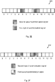
- the primary sidelink synchronization signals may be located consecutively in SC-FDMA symbol 6 and 7 and the secondary sidelink synchronization signals in SC-FDMA symbol 1 and 12, see Figure 8B .
- the arrangement disclosed in Figure 8B does not render reduced complexity in the receiver for several reasons.
- the receiver Once the receiver has acquired the OFDM/ SC-FDMA symbol timing by detecting the primary sidelink synchronization signal, it will proceed with detecting the secondary sidelink synchronization signals in order to obtain subframe timing, i.e., in which OFDM/ SC-FDMA symbol the subframe starts/ stops. It may then consider the primary sidelink synchronization signal as a known reference symbol from which it may estimate the channel. It would then be possible to coherently detect the secondary sidelink synchronization signals using channel estimates from the primary sidelink synchronization signal.
- the reference symbol i.e., primary sidelink synchronization signal
- the data symbol i.e., secondary sidelink synchronization signal
- the smallest distance between a primary sidelink synchronization signal and a secondary sidelink synchronization signal is 5 OFDM/ SC-FDMA symbols, which is not beneficial when the transmitter and/ or receiver are moving around since the channel estimate may become outdated. Due to this limitation, the receiver may need to use non-coherent secondary sidelink synchronization signal detection, yielding worse performance. It may be noted that for D2D communications, both the transmitter and receiver may be moving, which is in contrast to cellular communication systems.
- the receiver when it is detecting the primary sidelink synchronization signal, it typically is using a matched filter whose output is a correlation value. Due to noise and channel fading, it may not necessarily detect two correlation peaks although there are two primary sidelink synchronization signal symbols in the subframe. Therefore, it cannot know which of the two primary sidelink synchronization signal symbols it has detected.
- the distance in OFDM/ SC-FDMA symbols between the secondary sidelink synchronization signal in symbol 1 and the primary sidelink synchronization signals in symbol 6 and 7 respectively are different, i.e., four and five OFDM/ SC-FDMA symbols respectively. The same observation holds for the secondary sidelink synchronization signal in symbol 12.
- the receiver when the receiver has detected a correlation peak of a primary sidelink synchronization signal, it would have to blindly detect the secondary sidelink synchronization signal, since it does not know which primary sidelink synchronization signal symbol that was detected and consequentially would not know in which OFDM/ SC-FDMA symbol the secondary sidelink synchronization signal is located. Blind detection increases the complexity in the receiver and also results in worse secondary sidelink synchronization signal detection performance.
- the arrangement in Figure 8B is also not beneficial for saving transmit power in the transmitter since the primary sidelink synchronization signal and secondary sidelink synchronization signal symbols are spread out over the whole subframe. This makes it more difficult to turn off the power amplifier in order to save battery power.
- a transmitter configured to transmit a first type of synchronisation signal, in M 1 symbols l i , , 0 ⁇ i ⁇ ( M 1 - 1) of a subframe and a second type of synchronisation signal in M 2 symbols k j , 0 ⁇ j ⁇ ( M 2 - 1) of the subframe.
- the subframe comprises N symbols, wherein N ⁇ M 2 ⁇ M 1 ⁇ 2.
- the transmitter comprises a processor, configured to determine in which symbols l i of the subframe the synchronisation signal of the first type is to be transmitted.
- the processor is further configured to calculate in which symbols k j of the subframe, the synchronisation signal of the second type is to be transmitted, by placing each of the M 2 symbols k j at a one or more determined symbol distance from an associated symbol l i , wherein said one or more determined symbol distance between each of the M 2 symbols k j and the respective associated symbol l i is equal for all of the M 1 symbols l i in the subframe.
- the transmitter also comprises a transmitting circuit, configured to transmit the synchronisation signals of the first type in the determined M 1 symbols l i of the subframe, and to transmit the synchronisation signals of the second type in the calculated M 2 symbols k j of the subframe.
- An advantage thereby is that the receiver is enabled to easily detect a synchronisation signal of the second type, without having to perform blind detection. Thanks to the fixed distance between each symbol holding a synchronisation signal of the first type and each symbol holding a synchronisation signal of the second type, the receiver does not need to know which symbol of the plurality of symbols holding the synchronisation signal of the first type that has been detected in order to detect the synchronisation signal of the second type. Thereby time, energy and computational power are saved by the receiver, while improving the synchronisation between transmitter and receiver. Thus efficient and yet easily implemented synchronisation of transmitter and receiver is achieved.
- the one or more symbol distance between the determined M 1 symbols l i and each of the associated M 2 symbols k j may be determined from the first time instance after the cyclic prefix of the symbols l i , k j .
- An advantage thereby is that the receiver thereby is enabled to detect a synchronisation signal of the second type, only by detecting one synchronisation signal of the first type and by knowing the above specified algorithm and the set of integer offset values ⁇ j . Thereby synchronisation between transmitter and receiver is improved.
- the processor may be configured to establish the set of offset values ⁇ j such that:
- 1,2 and/or 3.
- the transmitter amplifier may be switched off when the symbols holding these synchronisation signals have been transmitted, until it is time to transmit corresponding symbol of the subsequent subframe holding synchronisation signals. Thereby energy is saved.
- the M 1 symbols l i may be determined to be distantly located from each other, such that: l i +1 ⁇ l i + N - 3.
- the M 1 symbols l i may have an equal cyclic prefix length and/ or wherein the M 2 symbols k j may have an equal cyclic prefix length.
- synchronisation signals of the first type are allocated to symbols having the same cyclic prefix length and synchronisation signals of the second type are allocated to symbols having the same cyclic prefix length, which may or may not be the same as that for the synchronisation signals of the first type.
- An advantage by having one single offset value ⁇ is that the receiver only is required to know this single offset value ⁇ . Thereby, the synchronisation between transmitter and receiver is enhanced.
- the first type of synchronisation signal and the second type of synchronisation signal may be dedicated for Device-to-Device (D2D) communication and the transmitter comprises a non-stationary unit.
- D2D Device-to-Device
- Synchronisation between non-stationary units is typically more crucial than between one stationary unit and one non-stationary unit, as both the non-stationary transmitter and receiver may drift in relation to a stationary network node and thereby also drift in relation to each other. Thanks to the provided transmitter, a robust and reliable, yet fast synchronisation protocol is achieved.
- the transmitter may comprise a user equipment (UE) operating within a 3rd Generation Partnership Project Long Term Evolution (3GPP LTE) system, and wherein the synchronisation signals of the first type may comprise a primary sidelink synchronization signal and wherein the synchronisation signals of the second type may comprise secondary sidelink synchronization signal.
- UE user equipment
- 3GPP LTE 3rd Generation Partnership Project Long Term Evolution
- a transmitter is provided, enabled for synchronisation in a 3GPP LTE environment.
- the first type of synchronisation signal, and/ or the second type of synchronisation signal may be based on any of Orthogonal Frequency-Division Multiplexing (OFDM) or Single Carrier-Frequency Division Multiple Access (SC-FDMA).
- OFDM Orthogonal Frequency-Division Multiplexing
- SC-FDMA Single Carrier-Frequency Division Multiple Access
- a transmitter is provided, enabled for synchronisation in a 3GPP LTE environment, in both directions between transmitter and receiver.
- a method in a transmitter for transmitting a first type of synchronisation signal in M 1 symbols l i, , 0 ⁇ i ⁇ ( M 1 - 1) of a subframe and a second type of synchronisation signal, comprising M 2 symbols k j , 0 ⁇ j ⁇ ( M 2 - 1) in the subframe, which subframe comprises N symbols, wherein N ⁇ M 2 ⁇ M 1 ⁇ 2.
- the method comprises determining in which M 1 symbols l i of the subframe, the synchronisation signal of the first type is to be transmitted.
- the method also comprises calculating in which M 2 symbols k j of the subframe, the synchronisation signal of the second type is to be transmitted by placing the M 2 symbols k j at a one or more determined symbol distance from an associated symbol l i , wherein said one or more determined symbol distance between each of the M 2 symbols k j and the respective associated symbol l i is equal between all of the M 1 symbols l i in the subframe and their respective associated M 2 symbols k j .
- the method also comprises transmitting the synchronisation signal of the first type in the determined M 1 symbols l i of the subframe, and the synchronisation signal of the second type in the calculated M 2 symbols k j of the subframe.
- An advantage thereby is that the receiver is enabled to easily detect a synchronisation signal of the second type, without having to perform blind detection. Thanks to the fixed distance between each symbol holding a synchronisation signal of the first type and each symbol holding a synchronisation signal of the second type, the receiver does not need to know which symbol of the plurality of symbols holding the synchronisation signal of the first type that has been detected in order to detect the synchronisation signal of the second type. Thereby time, energy and computational power are saved by the receiver. Thus efficient and yet easily implemented synchronisation of transmitter and receiver is achieved.
- the one or more symbol distance between the determined M 1 Symbols l i and each of the associated M 2 symbols k j may be determined from the first time instance after the cyclic prefix of the symbols l i , k j .
- An advantage thereby is that the receiver thereby is enabled to detect a synchronisation signal of the second type, only by detecting one synchronisation signal of the first type and by knowing the above specified algorithm and the set of integer offset values ⁇ j . Thereby synchronisation between transmitter and receiver is improved.
- the method may comprise establishing the set of offset values ⁇ j such that:
- 1,2 and/or 3.
- the transmitter amplifier may be switched off when the symbols holding these synchronisation signals have been transmitted, until it is time to transmit corresponding symbol of the subsequent subframe holding synchronisation signals. Thereby energy is saved.
- the M 1 symbols l i may be determined to be distantly located from each other, such that: l i +1 ⁇ l i + N - 3.
- the M 1 symbols l i may have an equal cyclic prefix length and/ or wherein the M 2 symbols k j may have an equal cyclic prefix length.
- synchronisation signals of the first type are allocated to symbols having the same cyclic prefix length and synchronisation signals of the second type are allocated to symbols having the same cyclic prefix length, which may or may not be the same as that for the synchronisation signals of the first type.
- An advantage by having one single offset value ⁇ is that the receiver only is required to know this single offset value ⁇ . Thereby, the synchronisation between transmitter and receiver is enhanced.
- the first type of synchronisation signal and the second type of synchronisation signal may be dedicated for Device-to-Device (D2D) communication and the transmitter comprises a non-stationary unit.
- D2D Device-to-Device
- Synchronisation between non-stationary units is typically more crucial than between one stationary unit and one non-stationary unit, as both the non-stationary transmitter and receiver may drift in relation to a stationary network node and thereby also drift in relation to each other. Thanks to the provided method, a robust and reliable, yet fast synchronisation protocol is achieved.
- the transmitter may comprise a user equipment (UE) operating within a 3rd Generation Partnership Project Long Term Evolution (3GPP LTE) system, and wherein the synchronisation signals of the first type may comprise primary sidelink synchronization signals and wherein the synchronisation signals of the second type may comprise secondary sidelink synchronization signals.
- UE user equipment
- 3GPP LTE 3rd Generation Partnership Project Long Term Evolution
- the first type of synchronisation signal, and/ or the second type of synchronisation signal may be based on any of Orthogonal Frequency-Division Multiplexing (OFDM) or Single Carrier-Frequency Division Multiple Access (SC-FDMA).
- OFDM Orthogonal Frequency-Division Multiplexing
- SC-FDMA Single Carrier-Frequency Division Multiple Access
- a receiver configured to detect a received first type of synchronisation signal, in M 1 symbols l i, , 0 ⁇ i ⁇ ( M 1 - 1) of a subframe and a second type of synchronisation signal, in M 2 symbols k j , 0 ⁇ j ⁇ ( M 2 - 1).
- the synchronisation signals are received in a subframe comprising N symbols, wherein N ⁇ M 2 ⁇ M 1 ⁇ 2.
- the receiver comprises a receiving circuit configured to receive the synchronisation signal of the first type in the M 1 symbols l i of the subframe.
- the receiver also comprises a processor, configured to establish a one or more determined symbol distance between a symbol k j and an associated symbol l i .
- the receiving circuit is additionally configured to calculate in which M 2 symbols k j of the subframe, the synchronisation signal of the second type is to be detected, wherein said one or more determined symbol distance between each of the M 2 symbols k j and the respective associated symbol l i is equal for all of the M 1 symbols l i in the subframe.
- An advantage thereby is that the receiver is enabled to easily detect a synchronisation signal of the second type, without having to perform blind detection. Thanks to the fixed distance between each symbol holding a synchronisation signal of the first type and each symbol holding a synchronisation signal of the second type, the receiver does not need to know which symbol of the plurality of symbols holding the synchronisation signal of the first type that has been detected in order to detect the synchronisation signal of the second type. Thereby time, energy and computational power are saved by the receiver. Thus efficient and yet easily implemented synchronisation of transmitter and receiver is achieved.
- An advantage thereby is that the receiver is enabled to detect a synchronisation signal of the second type, only by detecting one synchronisation signal of the first type and by knowing the above specified algorithm and the set of integer offset values ⁇ j . Thereby synchronisation between transmitter and receiver is improved.
- a method in a receiver configured to detect a first type of synchronisation signal, in M 1 symbols l i, , 0 ⁇ i ⁇ ( M 1 - 1) of a subframe and a second type of synchronisation signal, in M 2 symbols k j , received in the subframe, which subframe comprises N symbols, wherein N ⁇ M 2 ⁇ M 1 ⁇ 2.
- the method comprises determining in which M 1 symbols l i of the subframe, the synchronisation signal of the first type is received. Further the method comprises establishing a one or more determined symbol distance between each of the M 2 symbols k j and the respective associated symbol l i which is equal for all of the M 1 symbols l i in the subframe.
- the method comprises calculating in which M 2 symbols k j of the subframe, the synchronisation signal of the second type is to be received. Further the method comprises detecting the M 2 synchronisation signal of the second type in the calculated M 2 symbols k j of the subframe.
- An advantage thereby is that the receiver is enabled to easily detect a synchronisation signal of the second type, without having to perform blind detection. Thanks to the fixed distance between each symbol holding a synchronisation signal of the first type and each symbol holding a synchronisation signal of the second type, the receiver does not need to know which symbol of the plurality of symbols holding the synchronisation signal of the first type that has been detected in order to detect the synchronisation signal of the second type. Thereby time, energy and computational power are saved by the receiver. Thus efficient and yet easily implemented synchronisation of transmitter and receiver is achieved.
- a computer program in a transmitter according to the first aspect or any possible implementation thereof comprising program code for performing a method according to the second aspect, or any possible implementation thereof, when the computer program runs on a computer.
- An advantage thereby is that easy detection of a synchronisation signal of the second type is enabled, without having to perform blind detection. Thanks to the fixed distance between each symbol holding a synchronisation signal of the first type and each symbol holding a synchronisation signal of the second type, the receiver does not need to know which symbol of the plurality of symbols holding the synchronisation signal of the first type that has been detected in order to detect the synchronisation signal of the second type. Thereby time, energy and computational power are saved by the receiver. Thus efficient and yet easily implemented synchronisation of transmitter and receiver is achieved.
- a computer program in a receiver according to the third aspect, or any possible implementation thereof comprising program code for performing a method according to the fourth aspect, or any possible implementation thereof, when the computer program runs on a computer.
- An advantage thereby is that easy detection of a synchronisation signal of the second type is enabled, without having to perform blind detection. Thanks to the fixed distance between each symbol holding a synchronisation signal of the first type and each symbol holding a synchronisation signal of the second type, the receiver does not need to know which symbol of the plurality of symbols holding the synchronisation signal of the first type that has been detected in order to detect the synchronisation signal of the second type. Thereby time, energy and computational power are saved by the receiver. Thus efficient and yet easily implemented synchronisation of transmitter and receiver is achieved.
- a system for synchronising a transmitter and a receiver with each other.
- the system comprises a transmitter according to the first aspect and a receiver according to the third aspect which are synchronised with each other by transmitting a first type of synchronisation signal in M 1 symbols l i, , 0 ⁇ i ⁇ ( M 1 - 1) of a subframe and a second type of synchronisation signal, comprising M 2 symbols k j , 0 ⁇ j ⁇ ( M 2 - 1) in the subframe, which subframe comprises N symbols, wherein N ⁇ M 2 ⁇ M 1 ⁇ 2.
- the synchronisation further comprises determining in which M 1 symbols l i of the subframe, the synchronisation signal of the first type is to be transmitted. Further, the synchronisation also comprises calculating in which M 2 symbols k j of the subframe, the synchronisation signal of the second type is to be transmitted by placing the M 2 symbols k j at a one or more determined symbol distance from an associated symbol l i , wherein said one or more determined symbol distance between each of the M 2 symbols k j and the respective associated symbol l i is equal between all of the M 1 symbols l i in the subframe and their respective associated M 2 symbols k j . In further addition, the synchronisation also comprises transmitting the synchronisation signal of the first type in the determined M 1 symbols l i of the subframe, and the synchronisation signal of the second type in the calculated M 2 symbols k j of the subframe.
- An advantage thereby is that easy detection of a synchronisation signal of the second type is enabled, without having to perform blind detection. Thanks to the fixed distance between each symbol holding a synchronisation signal of the first type and each symbol holding a synchronisation signal of the second type, the receiver does not need to know which symbol of the plurality of symbols holding the synchronisation signal of the first type that has been detected in order to detect the synchronisation signal of the second type. Thereby time, energy and computational power are saved by the receiver. Thus efficient and yet easily implemented synchronisation of transmitter and receiver is achieved.
- Embodiments of the invention described herein are defined as a transmitter, a method in a transmitter, a receiver and a method in a receiver, which may be put into practice in the embodiments described below. These embodiments may, however, be exemplified and realised in many different forms and are not to be limited to the examples set forth herein; rather, these illustrative examples of embodiments are provided so that this disclosure will be thorough and complete.
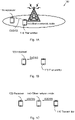
- Figure 1A is a schematic illustration over a wireless communication network 100 comprising a transmitter 110 , a receiver 120 and a radio network node 130.
- the transmitter 110 and/ or the receiver 120 may be mobile terminals, which may be served by the radio network node 130, thereby being connected to the wireless communication network 100.
- the transmitter 110 and the receiver 120 may be configured for D2D communication, and the transmitter 110 may send a D2D synchronisation signal to the receiver 120, for synchronisation between the devices 110, 120.
- the wireless communication network 100 may at least partly be based on radio access technologies such as, e.g., 3GPP LTE, LTE-Advanced, Evolved Universal Terrestrial Radio Access Network (E-UTRAN), Universal Mobile Telecommunications System (UMTS), Global System for Mobile Communications (originally: Groupe Special Mobile) (GSM)/ Enhanced Data rate for GSM Evolution (GSM/ EDGE), Wideband Code Division Multiple Access (WCDMA), Time Division Multiple Access (TDMA) networks, Frequency Division Multiple Access (FDMA) networks, Orthogonal FDMA (OFDMA) networks, Single-Carrier FDMA (SC-FDMA) networks, Worldwide Interoperability for Microwave Access (WiMax), or Ultra Mobile Broadband (UMB), High Speed Packet Access (HSPA) Evolved Universal Terrestrial Radio Access (E-UTRA), Universal Terrestrial Radio Access (UTRA), GSM EDGE Radio Access Network (GERAN), 3GPP2 CDMA technologies, e.g., CDMA2000 1x RTT and
- the wireless communication network 100 may be configured to operate according to the Time Division Duplex (TDD) and/ or the Frequency Division Duplex (FDD) principle, according to different embodiments.
- TDD Time Division Duplex
- FDD Frequency Division Duplex
- TDD is an application of time-division multiplexing to separate uplink and downlink signals in time, possibly with a Guard Period (GP) situated in the time domain between the uplink and downlink signalling.
- FDD means that the transmitter and receiver operate at different carrier frequencies.
- Figure 1A The purpose of the illustration in Figure 1A is to provide a simplified, general overview of an example of the wireless communication network 100 and the involved methods and nodes, such as the transmitter 110, the receiver 120 and the radio network node 130 herein described, and the functionalities involved.
- FIG. 1B illustrates an example wherein the transmitter 110 and the receiver 120 are situated outside any wireless communication network 100, i.e., LTE network.
- the transmitter 110 transmits a D2D synchronisation signal (D2DSS) to be received by the receiver 120, for synchronisation purposes.
- D2DSS D2D synchronisation signal
- FIG. 1C illustrates yet an embodiment of D2D communication, wherein multi-hop is illustrated.
- the transmitter 110 transmits a D2DSS to be received by the receiver 120, via an intermediately situated other network node 140.
- the wireless communication network 100 may comprise any other number and/ or combination of the discussed entities 110, 120, 130, 140.
- a plurality of transmitters 110, receivers 120, other network nodes 140 and another configuration of radio network nodes 130 may thus be involved in some of the herein disclosed embodiments.
- the other network node 140 may comprise a set of a plurality of other network nodes 140, according to some embodiments.
- the transmitter 110, the receiver 120 and/ or the other network node 140 may correspondingly be represented by, e.g., a wireless communication terminal, a mobile cellular phone, a Personal Digital Assistant (PDA), a wireless platform, a mobile station a user equipment, a tablet computer, a portable communication device, a laptop, a computer, a wireless terminal acting as a relay, a relay node, a mobile relay, a Customer Premises Equipment (CPE), a Fixed Wireless Access (FWA) nodes or any other kind of device configured to communicate wirelessly with each other by direct communication and possibly also with the radio network node 130, according to different embodiments and different vocabulary.
- PDA Personal Digital Assistant
- a wireless platform e.g., a wireless communication terminal, a mobile cellular phone, a Personal Digital Assistant (PDA), a wireless platform, a mobile station a user equipment, a tablet computer, a portable communication device, a laptop, a computer, a wireless terminal acting as a relay, a relay node
- the radio network node 130 and/ or the other network node 140 may be configured for downlink transmission and uplink reception, and may be referred to, respectively, as, e.g., a base station, a NodeB, an evolved Node Bs (eNB, or eNode B), a base transceiver station, an Access Point Base Station, a base station router, a Radio Base Station (RBS), a micro base station, a pico base station, a femto base station, a Home eNodeB, a sensor, a beacon device, a relay node, a repeater or any other network node configured for communication with the mobile stations within cell coverage over a wireless interface, depending, e.g., of the radio access technology and/ or terminology used.
- a base station e.g., a NodeB, an evolved Node Bs (eNB, or eNode B), a base transceiver station, an Access Point Base Station, a base station router, a Radio Base
- Some embodiments may define a modular implementation approach, and make it possible to reuse legacy systems such as, e.g., standards, algorithms, implementations, components and products.
- the transmitter 110 and the receiver 120 may synchronise by utilising two distinct types of synchronisation signals, transmitted in symbols in bursts, with a pre-defined inter-symbol spacing between the symbols for the two types of synchronisation signals within a burst.
- the herein discussed symbols may comprise, e.g., Orthogonal Frequency-Division Multiplexing (OFDM) or Single Carrier-Frequency Division Multiple Access (SC-FDMA) symbols in different embodiments.
- OFDM Orthogonal Frequency-Division Multiplexing
- SC-FDMA Single Carrier-Frequency Division Multiple Access
- the transmitter 110 may transmit two types of synchronisation signals, transmitted in symbols, such as, e.g., OFDM or SC-FDMA symbols, in bursts, with a pre-defined inter-symbol spacing between the symbols for the two types of synchronisation signals within a burst.
- symbols such as, e.g., OFDM or SC-FDMA symbols
- the receiver 120 may correspondingly detect two types of synchronisation signals, transmitted in symbols, such as, e.g., OFDM or SC-FDMA symbols, in bursts, with a pre-defined inter-symbol spacing between the symbols for the two types of synchronisation signals within a burst.
- symbols such as, e.g., OFDM or SC-FDMA symbols
- the receiver 120 may optionally utilise a repetitive signal property of the synchronisation signal of the first type, if consecutive symbols are utilised for transmitting the synchronisation signal of the first type.
- Several bursts may be transmitted contiguously after each other but at some point in time, there may be at least N symbols not comprising any synchronisation signals.
- a burst may be a subframe. It is noted that a burst may be confined to a subset of the symbols within a subframe, e.g., excluding the last symbol, which is not used for transmission for D2D communication in LTE.
- synchronisation signals Two types are defined; a first type of synchronisation signal and a second type of synchronisation signal.
- synchronisation signals may comprise different information and it may be assumed that both have to be successfully detected in order to acquire sufficient synchronisation. Furthermore, the first type of synchronisation signal typically has to be detected before detecting the second type of synchronisation signal.
- the first type of synchronisation signal may be generated from one or several length-63 Zadoff-Chu sequences, whose central element is punctured, resulting in a sequence of length-62.
- the second type of synchronisation signal may be generated from two interleaved length-31 sequences being derived from a set of m-sequences, resulting in a sequence of length-62.
- the value may be either predefined, or signalled, e.g., by Radio Resource Control (RRC) signalling to the receiver 120 prior to detecting the synchronisation signal.
- RRC Radio Resource Control
- between symbol l i and the associated symbol k i is equal for all symbols l i .
- M 2 p ⁇ M 1
- p > 1 is an integer
- k 0 l 0 + ⁇
- k 1 l 0 + ⁇ 1
- k 1 k 0 + ⁇ ⁇
- ⁇ 1 and ⁇ are predefined offset parameters, similar to ⁇ .
- a plurality of similar relations may be determined in embodiments when more than two symbols for the second type of synchronisation signal are associated with one symbol for the first type of synchronisation signal.
- M 2 may be 4 when p is set to 2; when M 1 is 2, M 2 may be 6 when p is set to 3; and/ or when M 1 is 3, M 2 may be 6 when p is set to 2.
- the first type of synchronisation signal may be transmitted in M 1 symbols l i , , 0 ⁇ i ⁇ ( M 1 - 1) of a subframe and the second type of synchronisation signal may be transmitted in M 2 symbols k j , 0 ⁇ j ⁇ ( M 2 - 1) of the subframe.
- the subframe comprises N symbols, wherein N ⁇ M 2 ⁇ M 1 ⁇ 2.
- between symbol l i and the associated symbol k j is equal for all symbols l i .
- is different from another symbol distance
- there may be several symbol distances for all symbols l i which however are the same for all symbols l i .
- M 2 > M 1 and M 2 ⁇ p ⁇ M 1 , where p is an integer.
- p is an integer.
- the symbol positions for ⁇ M 2 / M 1 ⁇ ⁇ M 1 of the symbols defined for the second type of synchronisation signals are determined according to previous embodiments. Consequently only the remaining M 2 - ⁇ M 2 / M 1 ⁇ ⁇ M 1 symbols for the second type of synchronisation signals may have additional inter-symbol spacing.
- the first and second type of synchronisation signals may be located readily close in order to accommodate coherent detection. This is achieved by arranging the synchronisation signals such that
- 1,2 or 3 which may be expected to offer sufficient channel estimation performance in a system 100 using LTE numerology, given that the maximum Primary Synchronisation Signal (PSS) and Secondary Synchronisation Signal (SSS) spacing is three symbols.
- PSS Primary Synchronisation Signal
- SSS Secondary Synchronisation Signal
- An advantage of using contiguously located symbols for the first type of synchronisation signal is that it may accommodate better synchronisation performance. For example, when the channel is not varying significantly between 2 symbols, it may be possible to improve the channel estimates by interpolating over the set of contiguously located symbols containing the first type of synchronisation signal.
- a synchronisation signal within a symbol may be detected by computing a differential correlation value obtained as an auto-correlation of the received signal.
- One desirable property of this is that the magnitude of the correlation value is not affected by any frequency offsets. This is desirable for D2D communications, especially when operating out-of-network-coverage as illustrated in Figure 1B and/ or Figure 1C , where the total frequency offset is due to both the transmitter 110 and the receiver 120. This may result in much larger frequency offsets than for typical cellular communications, since the radio network node 130, or eNodeB, may have much more accurate frequency oscillators than the mobile transmitter 110 and receiver 120.
- a repetitive signal from 2 contiguous symbols also may allow computing differential correlation values for repetitive samples from different symbols. Contiguously located symbols may therefore offer more robust detection under large frequency offsets.
- ⁇ 0 and the receiver 120 buffers samples from previous symbols, it may be possible to finalise the synchronisation (i.e., detecting the second type of synchronisation signal) right after the first type of synchronisation signal has been detected.
- a further embodiment may comprise using symbols l i +1 ⁇ l i + N - 3, which results in a maximum time-separation of the synchronisation signal of the first type, in a subframe where the last symbol may not be used for transmission.
- Time-diversity gains could also be obtained for the second type of synchronisation signal, e.g., if
- 1, also k i +1 ⁇ k i + N - 3.
- the transmitter 110, receiver 120 and methods therein are however neither limited to these examples, nor to the considered set of indices l 0 and l 1 .
- the second type of synchronisation signal may be detected without requirement of blind detection, which saves computing resources at the receiver 120.
- Figure 2A shows an embodiment of a subframe 200 , comprising 14 symbols labelled from 0 to 13.
- An advantage of the illustrated embodiment is that it may allow interpolation of channel estimates from the 2 contiguously located symbols (positions 6 and 7) comprising the first type of synchronisation signal.
- the subframe 200 may comprise any arbitrary number N of symbols, such as, e.g., 10, 11, 12, 13, 15, 16, ..., ⁇ , etc.
- N any arbitrary number of symbols, such as, e.g., 10, 11, 12, 13, 15, 16, ..., ⁇ , etc.
- the herein described embodiments of synchronisation are neither limited to, nor dependent upon the number of symbols within the subframe 200.
- Figure 2B illustrates another embodiment of the subframe 200, comprising 14 symbols labelled from 0 to 13.
- An advantage also of the illustrated embodiment in Figure 2B is that it may allow interpolation of channel estimates from the 2 contiguously located symbols (positions 6 and 7) comprising the first type of synchronisation signal.
- Figure 2C illustrates another embodiment of the subframe 200, comprising 14 symbols labelled from 0 to 13.
- An advantage of the arrangements in Figure 2C is that it offers the minimum separation between the symbols, i.e., 1 symbol distance spacing for the different types of synchronisation signals. Furthermore, there is 1 symbol comprising the synchronisation signal of the first type, which is located next to 2 symbols comprising the synchronisation signal of the second type, thus it may be used for channel estimation for both these 2 symbols.
- Figure 2D illustrates another embodiment of the subframe 200, comprising 14 symbols labelled from 0 to 13.
- An advantage of the arrangements in Figure 2D is that it offers the minimum separation between the symbols, i.e., 1 symbol distance spacing for the different types of synchronisation signals. Furthermore, there is 1 symbol comprising the synchronisation signal of the first type, which is located next to 2 symbols comprising the synchronisation signal of the second type, thus it may be used for channel estimation for both these 2 symbols.
- Figure 2E illustrates yet another embodiment of the subframe 200, comprising 14 symbols labelled from 0 to 13.
- Figure 2F illustrates yet another embodiment of the subframe 200, comprising 14 symbols labelled from 0 to 13.
- An advantage of the embodiments illustrated in Figures 2E and 2F is that it does not require a set of contiguous symbols. Thereby these embodiments may make it easier to insert the symbols for synchronisation considering that some of the symbols of the subframe 200 may not be available and/ or may be occupied for transmission of other channels and/ or signals.
- Figure 2G illustrates yet another embodiment of the subframe 200, comprising 14 symbols labelled from 0 to 13.
- positions 3 and 7 comprising a synchronisation signal of the first type
- positions 4, 5, 8 and 9 comprising a synchronisation signal of the second type.
- Figure 2H illustrates another embodiment of the subframe 200, comprising 14 symbols labelled from 0 to 13.
- positions 5 and 9 comprising a synchronisation signal of the first type
- positions 3, 4, 7 and 8 comprising a synchronisation signal of the second type.
- a symbol such as an OFDM or a SC-FDMA symbol, may comprise a data part and a Cyclic Prefix (CP), see Figure 2I .
- CP Cyclic Prefix
- At least one of the N OFDM/ SC-FDMA symbols has different cyclic prefix length than the other OFDM/ SC-FDMA symbols.
- synchronisation signals of the second type are also allocated to OFDM/ SC-FDMA symbols with the same cyclic prefix length, which may not be the same as that for the synchronisation signals of the first type. This assures that the OFDM/ SC-FDMA symbol position could be determined without blind decoding according to previous embodiments, even if the first type and second type of synchronisation signals are transmitted in OFDM/ SC-FDMA symbols with different cyclic prefix lengths.
- Figure 2K illustrates another example of a subframe 200 wherein pairs of synchronisation signals of the first type and second type respectively are located as far apart as possible within the subframe 200.
- Figure 3A and Figure 3B illustrate the distance d for two different orderings of the synchronisation signals.
- a condition for avoiding blind detection of the second type of synchronisation signal is that the distance d, which is the spacing between the first instant of the first type of synchronisation signal and the first instant of the second type of synchronisation signal, is constant for all OFDM/ SC-FDMA symbols containing the first type of synchronisation signals. This allows determining the position of the second type of synchronisation signal unambiguously even if the different types of synchronisation signals are located in OFDM/ SC-FDMA symbols with different cyclic prefix length.
- k i l i + ⁇ , ⁇ l i , where
- the described methods may comprise improvement of the synchronisation performance for synchronising the transmitter 110 and the receiver 120, by locating synchronisation signals in vicinity of each other such that coherent detection may be utilised. Also, by defining predefined symbol spacing relations between synchronisation signals such that blind detection may be avoided.
- power saving may be improved in the transmitter 110 when the synchronisation signals are located contiguously, as the power amplifier of the transmitter 110 may be switched off in between the transmitted signal bursts.
- the synchronisation signals may be distributed in the symbols of the subframe 200 according to minor variations of the above explicitly stated specifications. Also, the described transmitter 110, receiver 120 and methods may be applied in any system, wherein two types of synchronisation signals are transmitted in bursts.
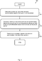
- Figure 4 is a flow chart illustrating embodiments of a method 400 for use in a transmitter 110, for transmitting a first type of synchronisation signal in M 1 symbols l i, , 0 ⁇ i ⁇ ( M 1 - 1) of a subframe 200 and a second type of synchronisation signal, comprising M 2 symbols k j , 0 ⁇ j ⁇ ( M 2 - 1) in the subframe 200.
- the subframe 200 comprises N symbols, wherein N ⁇ M 2 ⁇ M 1 ⁇ 2.
- the M 1 symbols l i may in some embodiments have an equal cyclic prefix length and/ or the M 2 symbols k j may have an equal cyclic prefix length.
- the first type of synchronisation signal and the second type of synchronisation signal are dedicated for Device-to-Device, D2D, communication and the transmitter 110 may comprise a non-stationary unit, such as, e.g., a mobile station or UE.
- the first type of synchronisation signal, and/ or the second type of synchronisation signal may be based on any of Orthogonal Frequency-Division Multiplexing (OFDM) or Single Carrier-Frequency Division Multiple Access (SC-FDMA) in different embodiments.
- OFDM Orthogonal Frequency-Division Multiplexing
- SC-FDMA Single Carrier-Frequency Division Multiple Access
- the transmitter 110 may be a user equipment (UE) operating within a 3rd Generation Partnership Project Long Term Evolution (3GPP LTE system) and wherein the synchronisation signals of the first type comprises primary sidelink synchronization signals and wherein the synchronisation signals of the second type comprises secondary sidelink synchronization signals, in some embodiments.
- UE user equipment
- 3GPP LTE system 3rd Generation Partnership Project Long Term Evolution
- the method 400 may comprise a number of actions 401-403. It is however to be noted that any, some or all of the described actions 401-403, may be performed in a somewhat different chronological order than the enumeration indicates, be performed simultaneously or even be performed in a completely reversed order according to different embodiments. Further, it is to be noted that some actions may be performed in a plurality of alternative manners according to different embodiments, and that some such alternative manners may be performed only within some, but not necessarily all embodiments.
- the method 400 may comprise the following actions:
- the M 1 symbols l i may be determined to be distantly located from each other, such that: l i +1 ⁇ l i + N - 3.
- the M 2 symbols k j are placed at a one or more determined 401 symbol distance from an associated symbol l i of the subframe 200, according to a calculation of when the synchronisation signal of the second type is to be transmitted, wherein said one or more determined symbol distance between each of the M 2 symbols k j and the respective associated symbol l i is equal between all of the M 1 symbols l i in the subframe 200 and their respective associated M 2 symbols k j .
- the one or more symbol distance between the determined 401 M 1 symbols l i and each of the associated M 2 symbols k j may be determined 401 from the first time instance after the cyclic prefix of the symbols l i , k j .
- the set of integer offset values ⁇ j may in some embodiments comprise
- 1,2 and/or 3.
- the synchronisation signal of the first type is transmitted in the determined 401 M 1 symbols l i of the subframe 200, and the synchronisation signal of the second type in the calculated 402 M 2 symbols k j of the subframe 200.
- the synchronisation signal may, in some embodiments, be transmitted over multiple hops between the transmitter 110 and the receiver 120, via one or more intermediate other nodes 140.
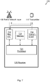
- Figure 5 illustrates an embodiment of a transmitter 110, configured to transmit a first type of synchronisation signal, in M 1 symbols l i , 0 ⁇ i ⁇ ( M 1 - 1) of a subframe 200 and a second type of synchronisation signal in M 2 symbols k j , 0 ⁇ j ⁇ ( M 2 - 1) of the subframe 200.
- the subframe 200 comprises N symbols, wherein N ⁇ M 2 ⁇ M 1 ⁇ 2.
- the illustrated transmitter 110 is configured to perform the method 400 according to any, some or all of the previously discussed actions 401-403.
- the first type of synchronisation signal and the second type of synchronisation signal may be dedicated for Device-to-Device (D2D) communication and the transmitter 110 may comprise a non-stationary unit.
- D2D Device-to-Device
- the transmitter 110 may comprise a user equipment (UE), operating within a 3rd Generation Partnership Project Long Term Evolution (3GPP LTE) system, and wherein the synchronisation signals of the first type comprises primary sidelink synchronization signals and wherein the synchronisation signals of the second type comprises secondary sidelink synchronization signals.
- UE user equipment
- 3GPP LTE 3rd Generation Partnership Project Long Term Evolution
- the first type of synchronisation signal, and/ or the second type of synchronisation signal may be based on any of Orthogonal Frequency-Division Multiplexing (OFDM), or Single Carrier-Frequency Division Multiple Access (SC-FDMA).
- OFDM Orthogonal Frequency-Division Multiplexing
- SC-FDMA Single Carrier-Frequency Division Multiple Access
- the transmitter 110 comprises a processor 520 , configured to determine in which symbols l i of the subframe 200 the synchronisation signal of the first type is to be transmitted, and in addition configured to calculate in which symbols k j of the subframe 200, the synchronisation signal of the second type is to be transmitted, by placing each of the M 2 symbols k j at a one or more determined symbol distance from an associated symbol l i , wherein said one or more determined symbol distance between each of the M 2 symbols k j and the respective associated symbol l i is equal for all of the M 1 symbols l i in the subframe 200.
- the one or more symbol distance between the determined M 1 symbols l i and each of the associated M 2 symbols k j may in some embodiments determined from the first time instance after the cyclic prefix of the symbols l i , k j .
- the processor 520 may be further configured to establish the set of offset values ⁇ j such that:
- 1,2 and/or 3.
- the processor 520 may be further configured to determine to locate the M 1 symbols l i distantly from each other, such that: l i +1 ⁇ l i + N - 3.
- the M 1 symbols l i may have an equal cyclic prefix length and/ or the M 2 symbols k j may have an equal cyclic prefix length.
- Such processor 520 may comprise one or more instances of a processing circuit, i.e., a Central Processing Unit (CPU), a processing unit, a processing circuit, a processor, an Application Specific Integrated Circuit (ASIC), a microprocessor, or other processing logic that may interpret and execute instructions.
- a processing circuit i.e., a Central Processing Unit (CPU), a processing unit, a processing circuit, a processor, an Application Specific Integrated Circuit (ASIC), a microprocessor, or other processing logic that may interpret and execute instructions.
- CPU Central Processing Unit
- ASIC Application Specific Integrated Circuit
- microprocessor may thus represent a processing circuitry comprising a plurality of processing circuits, such as, e.g., any, some or all of the ones enumerated above.
- the transmitter 110 also may comprise a transmitting circuit 530 , configured to transmit the synchronisation signals of the first type in the determined M 1 symbols l i of the subframe 200, and to transmit the synchronisation signals of the second type in the calculated M 2 symbols k j of the subframe 200.
- a transmitting circuit 530 configured to transmit the synchronisation signals of the first type in the determined M 1 symbols l i of the subframe 200, and to transmit the synchronisation signals of the second type in the calculated M 2 symbols k j of the subframe 200.
- the transmitter 110 may also comprise a receiving circuit 510 , configured for receiving signals, such as, e.g., synchronisation signals, from other network nodes 120, 130, 140 over a wireless interface according to some embodiments.
- a receiving circuit 510 configured for receiving signals, such as, e.g., synchronisation signals, from other network nodes 120, 130, 140 over a wireless interface according to some embodiments.
- the transmitter 110 may further comprise at least one memory 525 , according to some embodiments.
- the optional memory 525 may comprise a physical device utilised to store data or a program, i.e., a sequence of instructions, on a temporary or permanent basis.
- the memory 525 may comprise integrated circuits comprising silicon-based transistors. Further, the memory 525 may be volatile or non-volatile.
- Some or all of the above described actions 401-403 to be performed in the transmitter 110 may be implemented through the one or more processors 520 in the transmitter 110, together with a computer program product for performing at least some of the functions of the actions 401-403.
- a computer program comprising program code may perform a method 400 according to any, at least some, or all of the functions of the actions 401-403 for transmitting synchronisation signals, when the computer program is loaded into a processor 520 of the transmitter 110.
- a computer program product may comprise a computer readable storage medium storing program code thereon for use by the transmitter 110, for transmitting a first type of synchronisation signal in M 1 symbols l i, , 0 ⁇ i ⁇ ( M 1 - 1) of a subframe 200 and a second type of synchronisation signal, comprising M 2 symbols k j , 0 ⁇ j ⁇ ( M 2 - 1) in the subframe 200.
- the subframe 200 comprises N symbols, wherein N ⁇ M 2 ⁇ M 1 ⁇ 2.
- the program code comprising instructions for executing a method 400 that comprises determining 401 in which M 1 symbols l i of the subframe (200), the synchronisation signal of the first type is to be transmitted; calculating 402 in which M 2 symbols k j of the subframe 200, the synchronisation signal of the second type is to be transmitted by placing the M 2 symbols k j at a one or more determined symbol distance from an associated symbol l i , wherein said one or more determined symbol distance between each of the M 2 symbols k j and the respective associated symbol l i is equal between all of the M 1 symbols l i in the subframe 200 and their respective associated M 2 symbols k j ; and transmitting 403 the synchronisation signal of the first type in the determined M 1 symbols l i of the subframe 200, and the synchronisation signal of the second type in the calculated M 2 symbols k j of the subframe 200.
- the computer program product mentioned above may be provided for instance in the form of a data carrier carrying computer program code for performing at least some of the actions 401-403 according to some embodiments when being loaded into the processor 520.
- the data carrier may be, e.g., a hard disk, a CD ROM disc, a memory stick, an optical storage device, a magnetic storage device or any other appropriate medium such as a disk or tape that may hold machine readable data in a non transitory manner.
- the computer program product may furthermore be provided as computer program code on a server and downloaded to the transmitter 110 remotely, e.g., over an Internet or an intranet connection.
- Figure 6 is a flow chart illustrating embodiments of a method 600 for use in a receiver 120 for detecting a first type of synchronisation signal, in M 1 symbols l i, , 0 ⁇ i ⁇ ( M 1 - 1) of a subframe 200 and a second type of synchronisation signal, in M 2 symbols k j , received in the subframe 200.
- the subframe 200 comprises N symbols, wherein N ⁇ M 2 ⁇ M 1 ⁇ 2.
- the M 1 symbols l i may in some embodiments have an equal cyclic prefix length and/ or the M 2 symbols k j may have an equal cyclic prefix length.
- the first type of synchronisation signal and the second type of synchronisation signal may be dedicated for Device-to-Device, D2D, communication and the receiver 120 may comprises a non-stationary unit, such as, e.g., a mobile station or UE.
- the first type of synchronisation signal, and/ or the second type of synchronisation signal may be based on any of Orthogonal Frequency-Division Multiplexing (OFDM) or Single Carrier-Frequency Division Multiple Access (SC-FDMA) in different embodiments.
- OFDM Orthogonal Frequency-Division Multiplexing
- SC-FDMA Single Carrier-Frequency Division Multiple Access
- the receiver 120 may be a user equipment (UE) operating within a 3rd Generation Partnership Project Long Term Evolution (3GPP LTE system) and wherein the synchronisation signals of the first type comprises primary sidelink synchronization signals and wherein the synchronisation signals of the second type comprises secondary sidelink synchronization signals, in some embodiments.
- UE user equipment
- 3GPP LTE system 3rd Generation Partnership Project Long Term Evolution
- the method 600 may comprise a number of actions 601-604. It is however to be noted that any, some or all of the described actions 601-604, may be performed in a somewhat different chronological order than the enumeration indicates, be performed simultaneously or even be performed in a completely reversed order according to different embodiments. Further, it is to be noted that some actions may be performed in a plurality of alternative manners according to different embodiments, and that some such alternative manners may be performed only within some, but not necessarily all embodiments.
- the method 600 may comprise the following actions:
- the M 1 symbols l i may be determined to be distantly located from each other, such that: l i +1 ⁇ l i + N - 3.
- a one or more determined symbol distance between each of the M 2 symbols k j and the respective associated symbol l i is established, which is equal for all of the M 1 symbols l i in the subframe 200.
- the one or more symbol distance between the determined 601 M 1 symbols l i and each of the associated M 2 symbols k j may be determined 601 from the first time instance after the cyclic prefix of the symbols l i , k j .
- the set of integer offset values ⁇ j may in some embodiments comprise
- 1,2 and/or 3.
- the M 2 synchronisation signal of the second type is detected in the calculated 603 M 2 symbols k j of the subframe 200.
- Figure 7 illustrates an embodiment of a receiver 120, configured to detect a received synchronisation signal in M 1 symbols l i, , 0 ⁇ i ⁇ ( M 1 - 1) of a subframe 200 and a second type of synchronisation signal, in M 2 symbols k j , 0 ⁇ j ⁇ ( M 2 - 1).
- the signals are received in a subframe 200 comprising N symbols, wherein N ⁇ M 2 ⁇ M 1 ⁇ 2.
- the receiver 120 is configured to perform the above described method 600, according to at least some actions 601-604.
- the first type of synchronisation signal and the second type of synchronisation signal may be dedicated for Device-to-Device, D2D, communication and the receiver 120 may comprises a non-stationary unit, such as, e.g., a mobile station or UE.
- the first type of synchronisation signal, and/ or the second type of synchronisation signal may be based on any of Orthogonal Frequency-Division Multiplexing (OFDM) or Single Carrier-Frequency Division Multiple Access (SC-FDMA) in different embodiments.
- OFDM Orthogonal Frequency-Division Multiplexing
- SC-FDMA Single Carrier-Frequency Division Multiple Access
- the receiver 120 may be a user equipment (UE) operating within a 3rd Generation Partnership Project Long Term Evolution (3GPP LTE system) and wherein the synchronisation signals of the first type comprises primary sidelink synchronization signals and wherein the synchronisation signals of the second type comprises secondary sidelink synchronization signals, in some embodiments.
- UE user equipment
- 3GPP LTE system 3rd Generation Partnership Project Long Term Evolution
- the receiver 120 comprises a receiving circuit 710 , configured for receiving a signal such as, e.g., a synchronisation signal, from, e.g., the transmitter 110.
- the received signal, i.e., synchronisation signal may be of the first type in the M 1 symbols l i of the subframe 200.
- the receiving circuit 710 may be configured for receiving radio signals of various types over a wireless interface from a plurality of transmitting entities, such as other network nodes 140, or the radio network node 130.
- the receiver 120 comprises a processor 720 , configured to establish a one or more determined symbol distance between a symbol k j and an associated symbol l i , and in addition configured to calculate in which M 2 symbols k j of the subframe 200, the synchronisation signal of the second type is to be detected.
- the one or more determined symbol distance between each of the M 2 symbols k j and the respective associated symbol l i is equal for all of the M 1 symbols l i in the subframe 200.
- Such processor 720 may comprise one or more instances of a processing circuit, i.e., a Central Processing Unit (CPU), a processing unit, a processing circuit, a processor, an Application Specific Integrated Circuit (ASIC), a microprocessor, or other processing logic that may interpret and execute instructions.
- a processing circuit i.e., a Central Processing Unit (CPU), a processing unit, a processing circuit, a processor, an Application Specific Integrated Circuit (ASIC), a microprocessor, or other processing logic that may interpret and execute instructions.
- CPU Central Processing Unit
- ASIC Application Specific Integrated Circuit
- microprocessor may thus represent a processing circuitry comprising a plurality of processing circuits, such as, e.g., any, some or all of the ones enumerated above.
- the receiver 120 may also in some embodiments comprise a transmitting circuit 730 , configured for transmitting a wireless signal comprising, e.g., a synchronisation signal.
- a transmitting circuit 730 configured for transmitting a wireless signal comprising, e.g., a synchronisation signal.
- the receiver 120 may further comprise at least one memory 725 , according to some embodiments.
- the optional memory 725 may comprise a physical device utilised to store data or programs, i.e., sequences of instructions, on a temporary or permanent basis.
- the memory 725 may comprise integrated circuits comprising silicon-based transistors. Further, the memory 725 may be volatile or non-volatile.
- the term “and/ or” comprises any and all combinations of one or more of the associated listed items.
- the singular forms “a”, “an” and “the” are to be interpreted as “at least one”, thus also possibly comprising a plurality of entities of the same kind, unless expressly stated otherwise.
- the terms “includes”, “comprises”, “including” and/ or “comprising” specifies the presence of stated features, actions, integers, steps, operations, elements, and/ or components, but do not preclude the presence or addition of one or more other features, actions, integers, steps, operations, elements, components, and/ or groups thereof.
Landscapes
- Engineering & Computer Science (AREA)
- Computer Networks & Wireless Communication (AREA)
- Signal Processing (AREA)
- Mobile Radio Communication Systems (AREA)
- Synchronisation In Digital Transmission Systems (AREA)
Priority Applications (2)
| Application Number | Priority Date | Filing Date | Title |
|---|---|---|---|
| ES21211965T ES3059922T3 (en) | 2014-09-23 | 2014-09-23 | Transmitter, receiver and methods for transmitting/ receiving synchronisation signals |
| EP21211965.5A EP4024728B1 (fr) | 2014-09-23 | 2014-09-23 | Émetteur, récepteur et procédés permettant de transmettre/recevoir des signaux de synchronisation |
Applications Claiming Priority (3)
| Application Number | Priority Date | Filing Date | Title |
|---|---|---|---|
| EP14772133.6A EP3036844B1 (fr) | 2014-09-23 | 2014-09-23 | Émetteur, récepteur et procédés permettant de transmettre/recevoir des signaux de synchronisation |
| PCT/EP2014/070239 WO2016045704A1 (fr) | 2014-09-23 | 2014-09-23 | Émetteur, récepteur et procédés permettant de transmettre/recevoir des signaux de synchronisation |
| EP21211965.5A EP4024728B1 (fr) | 2014-09-23 | 2014-09-23 | Émetteur, récepteur et procédés permettant de transmettre/recevoir des signaux de synchronisation |
Related Parent Applications (1)
| Application Number | Title | Priority Date | Filing Date |
|---|---|---|---|
| EP14772133.6A Division EP3036844B1 (fr) | 2014-09-23 | 2014-09-23 | Émetteur, récepteur et procédés permettant de transmettre/recevoir des signaux de synchronisation |
Publications (2)
| Publication Number | Publication Date |
|---|---|
| EP4024728A1 true EP4024728A1 (fr) | 2022-07-06 |
| EP4024728B1 EP4024728B1 (fr) | 2025-11-26 |
Family
ID=51610115
Family Applications (2)
| Application Number | Title | Priority Date | Filing Date |
|---|---|---|---|
| EP14772133.6A Active EP3036844B1 (fr) | 2014-09-23 | 2014-09-23 | Émetteur, récepteur et procédés permettant de transmettre/recevoir des signaux de synchronisation |
| EP21211965.5A Active EP4024728B1 (fr) | 2014-09-23 | 2014-09-23 | Émetteur, récepteur et procédés permettant de transmettre/recevoir des signaux de synchronisation |
Family Applications Before (1)
| Application Number | Title | Priority Date | Filing Date |
|---|---|---|---|
| EP14772133.6A Active EP3036844B1 (fr) | 2014-09-23 | 2014-09-23 | Émetteur, récepteur et procédés permettant de transmettre/recevoir des signaux de synchronisation |
Country Status (9)
| Country | Link |
|---|---|
| US (1) | US11259259B2 (fr) |
| EP (2) | EP3036844B1 (fr) |
| JP (1) | JP6262849B2 (fr) |
| KR (1) | KR101793567B1 (fr) |
| CN (3) | CN105659675B (fr) |
| CA (1) | CA2926233C (fr) |
| ES (1) | ES3059922T3 (fr) |
| RU (1) | RU2625816C1 (fr) |
| WO (1) | WO2016045704A1 (fr) |
Cited By (1)
| Publication number | Priority date | Publication date | Assignee | Title |
|---|---|---|---|---|
| US11974447B2 (en) | 2019-06-14 | 2024-04-30 | Semiconductor Energy Laboratory Co., Ltd. | Light-emitting device, light-emitting apparatus, electronic device, and lighting device |
Families Citing this family (27)
| Publication number | Priority date | Publication date | Assignee | Title |
|---|---|---|---|---|
| WO2015065017A1 (fr) * | 2013-10-28 | 2015-05-07 | 엘지전자 주식회사 | Procédé et appareil d'émission et de réception d'un signal pour un terminal dispositif-à-dispositif dans un système de communication sans fil |
| CN114599119A (zh) | 2014-10-31 | 2022-06-07 | 三菱电机株式会社 | 无线通信系统、基站及通信终端 |
| US10027471B2 (en) * | 2015-06-11 | 2018-07-17 | Avago Technologies General Ip (Singapore) Pte. Ltd. | Synchronization and training stage operation |
| CN107634924B (zh) * | 2016-07-18 | 2020-08-11 | 中兴通讯股份有限公司 | 同步信号的发送、接收方法及装置、传输系统 |
| US9942069B2 (en) * | 2016-08-25 | 2018-04-10 | Intel IP Corporation | Methods and devices for frequency shift detection |
| CN107820273B (zh) * | 2016-09-14 | 2020-05-19 | 深圳市中兴微电子技术有限公司 | 一种检测D2D中sidelink的同步信号的方法及装置 |
| US10624066B2 (en) | 2016-11-04 | 2020-04-14 | Telefonaktiebolaget Lm Ericsson (Publ) | Method and apparatus for control-signal transmission in a wireless communication system |
| US11509515B2 (en) | 2016-12-16 | 2022-11-22 | Qualcomm Incorporated | Synchronization signal transmission and detection |
| US10506535B2 (en) * | 2017-01-13 | 2019-12-10 | Lg Electronics Inc. | Method for terminal transmitting sidelink in wireless communication system, and terminal using same |
| US10813063B2 (en) * | 2017-03-15 | 2020-10-20 | Qualcomm Incorporated | Synchronization signal transmission in a new radio wireless communication system |
| JP6955880B2 (ja) * | 2017-03-17 | 2021-10-27 | 株式会社東芝 | 無線通信システムおよび無線通信方法 |
| CN109391443B (zh) * | 2017-08-11 | 2021-12-14 | 华为技术有限公司 | 同步信号块指示及确定方法、网络设备和终端设备 |
| CN111279762B (zh) * | 2017-11-27 | 2021-12-28 | 华为技术有限公司 | 同步方法及装置 |
| CN110086582A (zh) * | 2018-01-26 | 2019-08-02 | 中兴通讯股份有限公司 | 一种信道测量方法和系统、第一通信节点及第二通信节点 |
| KR102452023B1 (ko) | 2018-02-09 | 2022-10-06 | 광동 오포 모바일 텔레커뮤니케이션즈 코포레이션 리미티드 | 동기화 신호의 송신 방법, 기기 및 컴퓨터 저장 매체 |
| CN110768771B (zh) | 2018-07-27 | 2021-07-27 | 维沃移动通信有限公司 | 同步信号传输方法及终端 |
| WO2020061921A1 (fr) * | 2018-09-27 | 2020-04-02 | 富士通株式会社 | Procédés et dispositifs pour envoyer et recevoir de signaux de référence |
| CN111147162B (zh) * | 2018-11-02 | 2021-08-24 | 大唐移动通信设备有限公司 | 一种测量信号的传输方法、装置及设备 |
| CN111148063B (zh) * | 2018-11-02 | 2022-04-15 | 大唐移动通信设备有限公司 | 一种测量信号的传输方法、装置及设备 |
| SG11202104925RA (en) | 2018-11-15 | 2021-06-29 | Beijing Xiaomi Mobile Software Co Ltd | Method and apparatus for broadcasting configuration information of synchronizing signal block, and method and apparatus for receiving configuration information of synchronizing signal block |
| US11476899B2 (en) * | 2019-04-18 | 2022-10-18 | Huawei Technologies Co., Ltd. | Uplink multi-user equipment (UE) cooperative transmission |
| CN110278610B (zh) * | 2019-05-28 | 2022-07-22 | 华为技术有限公司 | 一种资源配置方法及通信装置 |
| US11477849B2 (en) | 2019-07-30 | 2022-10-18 | Huawei Technologies Co., Ltd. | Method and apparatus for cooperation among devices in transmissions over a Uu interface |
| US12335881B2 (en) * | 2020-01-21 | 2025-06-17 | Qualcomm Incorporated | Power-efficient sidelink synchronization signal transmission |
| US12490212B2 (en) * | 2022-03-28 | 2025-12-02 | Spectric Labs, Inc. | Method for performing synchronization in distributed carrier communications |
| CN115296784B (zh) * | 2022-08-10 | 2023-10-20 | 横川机器人(深圳)有限公司 | 伺服驱动器低延时同步方法 |
| US20240251332A1 (en) * | 2023-01-25 | 2024-07-25 | Qualcomm Incorporated | Primary synchronization signal burst that is separate from a secondary synchronization signal burst |
Citations (1)
| Publication number | Priority date | Publication date | Assignee | Title |
|---|---|---|---|---|
| WO2012165904A2 (fr) * | 2011-06-01 | 2012-12-06 | Samsung Electronics Co., Ltd. | Procédés et appareil permettant de transmettre et de recevoir un signal de synchronisation et des informations de système dans un système de communication sans fil |
Family Cites Families (15)
| Publication number | Priority date | Publication date | Assignee | Title |
|---|---|---|---|---|
| ES2188370B1 (es) | 2001-05-21 | 2004-10-16 | Diseño De Sistemas En Silicio, S.A. | Procedimiento para la sincronizacion en el enlace descendente de multiples usuarios en un sistema de transmision punto a multipunto con modulacion ofdm. |
| US7894417B2 (en) | 2005-11-01 | 2011-02-22 | Nokia Corporation | Signal arrangement for multi-bandwidth OFDM system |
| CN101060513A (zh) * | 2006-04-17 | 2007-10-24 | 北京三星通信技术研究有限公司 | 传送循环前缀信息的方法 |
| US9137075B2 (en) * | 2007-02-23 | 2015-09-15 | Telefonaktiebolaget Lm Ericsson (Publ) | Subcarrier spacing identification |
| US8842701B2 (en) * | 2012-09-26 | 2014-09-23 | Metanoia Communications Inc. | LTE-advanced primary synchronization signal detection |
| CN104969488B (zh) * | 2013-01-31 | 2019-04-23 | Lg 电子株式会社 | 用于在无线电通信系统中设置用于d2d(设备对设备)通信的循环前缀的方法及其设备 |
| KR102045339B1 (ko) * | 2013-04-26 | 2019-11-15 | 삼성전자 주식회사 | 기기 대 기기 무선 통신에서의 발견 신호 자원 지시 방법 |
| KR101525230B1 (ko) | 2013-05-31 | 2015-06-01 | 주식회사 진켐 | 시알산 유도체의 제조방법 |
| CN103354528B (zh) * | 2013-06-28 | 2017-05-03 | 北京智谷睿拓技术服务有限公司 | 多流同步方法及装置 |
| KR102243662B1 (ko) * | 2013-09-01 | 2021-04-23 | 엘지전자 주식회사 | 무선 통신 시스템에서 d2d(device-to-device) 통신을 위한 동기화 신호 전송 방법 및 이를 위한 장치 |
| RU2627739C1 (ru) * | 2013-09-11 | 2017-08-11 | Хуавей Текнолоджиз Ко., Лтд. | Способ конфигурации опорного сигнала информации о состоянии канала и базовая станция |
| SG11201602473SA (en) | 2013-11-27 | 2016-04-28 | Ericsson Telefon Ab L M | Network node, wireless device, methods therein, for sending and detecting, respectively, synchronization signal and an associated information |
| WO2015111973A1 (fr) * | 2014-01-24 | 2015-07-30 | 엘지전자 주식회사 | Procédé et appareil d'acquisition de synchronisation par un terminal de dispositif à dispositif dans un système de communication sans fil |
| CN106416305B (zh) * | 2014-01-31 | 2019-11-01 | 华为技术有限公司 | 小区发现设备、网络及方法 |
| KR102396041B1 (ko) * | 2014-05-09 | 2022-05-10 | 엘지전자 주식회사 | 무선 통신 시스템에서 단말 간 직접 통신을 위한 동기화 신호를 전송하는 방법 및 이를 위한 장치 |
-
2014
- 2014-09-23 CN CN201480048734.5A patent/CN105659675B/zh active Active
- 2014-09-23 KR KR1020167010428A patent/KR101793567B1/ko active Active
- 2014-09-23 EP EP14772133.6A patent/EP3036844B1/fr active Active
- 2014-09-23 JP JP2016519952A patent/JP6262849B2/ja active Active
- 2014-09-23 ES ES21211965T patent/ES3059922T3/es active Active
- 2014-09-23 EP EP21211965.5A patent/EP4024728B1/fr active Active
- 2014-09-23 WO PCT/EP2014/070239 patent/WO2016045704A1/fr not_active Ceased
- 2014-09-23 CA CA2926233A patent/CA2926233C/fr active Active
- 2014-09-23 CN CN201910463718.7A patent/CN110190896B/zh active Active
- 2014-09-23 RU RU2016119577A patent/RU2625816C1/ru active
- 2014-09-23 CN CN201910465245.4A patent/CN110266371B/zh active Active
-
2016
- 2016-08-29 US US15/250,543 patent/US11259259B2/en active Active
Patent Citations (1)
| Publication number | Priority date | Publication date | Assignee | Title |
|---|---|---|---|---|
| WO2012165904A2 (fr) * | 2011-06-01 | 2012-12-06 | Samsung Electronics Co., Ltd. | Procédés et appareil permettant de transmettre et de recevoir un signal de synchronisation et des informations de système dans un système de communication sans fil |
Non-Patent Citations (3)
| Title |
|---|
| HUAWEI ET AL: "D2DSS design", vol. RAN WG1, no. Seoul, Korea; 20140519 - 20140523, 18 May 2014 (2014-05-18), XP050789457, Retrieved from the Internet <URL:http://www.3gpp.org/ftp/Meetings_3GPP_SYNC/RAN1/RAN1/Docs/> [retrieved on 20140518] * |
| HUAWEI ET AL: "Remaining details of D2D synchronization signals", vol. RAN WG1, no. Dresden, Germany; 20140818 - 20140821, 17 August 2014 (2014-08-17), XP050788328, Retrieved from the Internet <URL:http://www.3gpp.org/ftp/Meetings_3GPP_SYNC/RAN1/Docs/> [retrieved on 20140817] * |
| QUALCOMM INCORPORATED: "Signal Design for D2D Synchronization", vol. RAN WG1, no. Dresden, Germany; 20140818 - 20140822, 17 August 2014 (2014-08-17), XP050788444, Retrieved from the Internet <URL:http://www.3gpp.org/ftp/Meetings_3GPP_SYNC/RAN1/Docs/> [retrieved on 20140817] * |
Cited By (2)
| Publication number | Priority date | Publication date | Assignee | Title |
|---|---|---|---|---|
| US11974447B2 (en) | 2019-06-14 | 2024-04-30 | Semiconductor Energy Laboratory Co., Ltd. | Light-emitting device, light-emitting apparatus, electronic device, and lighting device |
| US12302685B2 (en) | 2019-06-14 | 2025-05-13 | Semiconductor Energy Laboratory Co., Ltd. | Light-emitting device, light-emitting apparatus, electronic device, and lighting device |
Also Published As
| Publication number | Publication date |
|---|---|
| CN110190896B (zh) | 2024-01-16 |
| CN105659675B (zh) | 2019-05-28 |
| KR101793567B1 (ko) | 2017-11-03 |
| EP3036844B1 (fr) | 2021-12-29 |
| ES3059922T3 (en) | 2026-03-24 |
| US20170013577A1 (en) | 2017-01-12 |
| KR20160060695A (ko) | 2016-05-30 |
| CN110266371A (zh) | 2019-09-20 |
| CN105659675A (zh) | 2016-06-08 |
| EP3036844A1 (fr) | 2016-06-29 |
| RU2625816C1 (ru) | 2017-07-19 |
| CA2926233A1 (fr) | 2016-03-31 |
| CN110190896A (zh) | 2019-08-30 |
| JP2017513244A (ja) | 2017-05-25 |
| JP6262849B2 (ja) | 2018-01-17 |
| CA2926233C (fr) | 2018-11-06 |
| WO2016045704A1 (fr) | 2016-03-31 |
| US11259259B2 (en) | 2022-02-22 |
| CN110266371B (zh) | 2021-10-22 |
| EP4024728B1 (fr) | 2025-11-26 |
Similar Documents
| Publication | Publication Date | Title |
|---|---|---|
| US11259259B2 (en) | Transmitter, receiver and methods for transmitting/ receiving synchronisation signals | |
| US10306573B2 (en) | System and method for transmitting a synchronization signal | |
| US10721701B2 (en) | Transmitter, receiver and method for generating synchronization signals | |
| US10034253B2 (en) | Cell search procedure frame format | |
| EP3493621A1 (fr) | Dispositif terminal, procédé de communication et circuit intégré | |
| US10602515B2 (en) | Guard band with synchronization information | |
| CN114270977B (zh) | 下行链路控制信息的发送和接收 | |
| WO2015034309A1 (fr) | Procédé et appareil pour détecter le signal de synchronisation de liaison montante de chaque niveau dans un système d'accès sans fil supportant une bande à haute fréquence | |
| EP3742636A1 (fr) | Procédé et dispositif de transmission de signaux de référence | |
| JP7118011B2 (ja) | 基地局、同期信号送信方法、及び無線通信システム | |
| CN113227819B (zh) | 用于异步装置和无时间帧结构的装置处的信号检测的系统和方法 | |
| JP6559763B2 (ja) | 送信機、受信機、および同期信号を送信/受信するための方法 | |
| US10097326B2 (en) | Communication method for MBMS and apparatus using same |
Legal Events
| Date | Code | Title | Description |
|---|---|---|---|
| PUAI | Public reference made under article 153(3) epc to a published international application that has entered the european phase |
Free format text: ORIGINAL CODE: 0009012 |
|
| STAA | Information on the status of an ep patent application or granted ep patent |
Free format text: STATUS: THE APPLICATION HAS BEEN PUBLISHED |
|
| AC | Divisional application: reference to earlier application |
Ref document number: 3036844 Country of ref document: EP Kind code of ref document: P |
|
| AK | Designated contracting states |
Kind code of ref document: A1 Designated state(s): AL AT BE BG CH CY CZ DE DK EE ES FI FR GB GR HR HU IE IS IT LI LT LU LV MC MK MT NL NO PL PT RO RS SE SI SK SM TR |
|
| STAA | Information on the status of an ep patent application or granted ep patent |
Free format text: STATUS: REQUEST FOR EXAMINATION WAS MADE |
|
| 17P | Request for examination filed |
Effective date: 20221229 |
|
| RBV | Designated contracting states (corrected) |
Designated state(s): AL AT BE BG CH CY CZ DE DK EE ES FI FR GB GR HR HU IE IS IT LI LT LU LV MC MK MT NL NO PL PT RO RS SE SI SK SM TR |
|
| STAA | Information on the status of an ep patent application or granted ep patent |
Free format text: STATUS: EXAMINATION IS IN PROGRESS |
|
| 17Q | First examination report despatched |
Effective date: 20230511 |
|
| GRAP | Despatch of communication of intention to grant a patent |
Free format text: ORIGINAL CODE: EPIDOSNIGR1 |
|
| STAA | Information on the status of an ep patent application or granted ep patent |
Free format text: STATUS: GRANT OF PATENT IS INTENDED |
|
| INTG | Intention to grant announced |
Effective date: 20250718 |
|
| P01 | Opt-out of the competence of the unified patent court (upc) registered |
Free format text: CASE NUMBER: UPC_APP_5388_4024728/2025 Effective date: 20250829 |
|
| GRAS | Grant fee paid |
Free format text: ORIGINAL CODE: EPIDOSNIGR3 |
|
| GRAA | (expected) grant |
Free format text: ORIGINAL CODE: 0009210 |
|
| STAA | Information on the status of an ep patent application or granted ep patent |
Free format text: STATUS: THE PATENT HAS BEEN GRANTED |
|
| AC | Divisional application: reference to earlier application |
Ref document number: 3036844 Country of ref document: EP Kind code of ref document: P |
|
| AK | Designated contracting states |
Kind code of ref document: B1 Designated state(s): AL AT BE BG CH CY CZ DE DK EE ES FI FR GB GR HR HU IE IS IT LI LT LU LV MC MK MT NL NO PL PT RO RS SE SI SK SM TR |
|
| REG | Reference to a national code |
Ref country code: CH Ref legal event code: F10 Free format text: ST27 STATUS EVENT CODE: U-0-0-F10-F00 (AS PROVIDED BY THE NATIONAL OFFICE) Effective date: 20251126 Ref country code: GB Ref legal event code: FG4D |
|
| REG | Reference to a national code |
Ref country code: IE Ref legal event code: FG4D |
|
| REG | Reference to a national code |
Ref country code: DE Ref legal event code: R096 Ref document number: 602014092596 Country of ref document: DE |
|
| REG | Reference to a national code |
Ref country code: ES Ref legal event code: FG2A Ref document number: 3059922 Country of ref document: ES Kind code of ref document: T3 Effective date: 20260324 |
|
| REG | Reference to a national code |
Ref country code: NL Ref legal event code: MP Effective date: 20251126 |
|
| REG | Reference to a national code |
Ref country code: LT Ref legal event code: MG9D |
|
| PG25 | Lapsed in a contracting state [announced via postgrant information from national office to epo] |
Ref country code: NO Free format text: LAPSE BECAUSE OF FAILURE TO SUBMIT A TRANSLATION OF THE DESCRIPTION OR TO PAY THE FEE WITHIN THE PRESCRIBED TIME-LIMIT Effective date: 20260226 |
|
| PG25 | Lapsed in a contracting state [announced via postgrant information from national office to epo] |
Ref country code: HR Free format text: LAPSE BECAUSE OF FAILURE TO SUBMIT A TRANSLATION OF THE DESCRIPTION OR TO PAY THE FEE WITHIN THE PRESCRIBED TIME-LIMIT Effective date: 20251126 Ref country code: AT Free format text: LAPSE BECAUSE OF FAILURE TO SUBMIT A TRANSLATION OF THE DESCRIPTION OR TO PAY THE FEE WITHIN THE PRESCRIBED TIME-LIMIT Effective date: 20251126 Ref country code: FI Free format text: LAPSE BECAUSE OF FAILURE TO SUBMIT A TRANSLATION OF THE DESCRIPTION OR TO PAY THE FEE WITHIN THE PRESCRIBED TIME-LIMIT Effective date: 20251126 |
|
| REG | Reference to a national code |
Ref country code: AT Ref legal event code: MK05 Ref document number: 1862182 Country of ref document: AT Kind code of ref document: T Effective date: 20251126 |
|
| PG25 | Lapsed in a contracting state [announced via postgrant information from national office to epo] |
Ref country code: NL Free format text: LAPSE BECAUSE OF FAILURE TO SUBMIT A TRANSLATION OF THE DESCRIPTION OR TO PAY THE FEE WITHIN THE PRESCRIBED TIME-LIMIT Effective date: 20251126 |
|
| PG25 | Lapsed in a contracting state [announced via postgrant information from national office to epo] |
Ref country code: RS Free format text: LAPSE BECAUSE OF FAILURE TO SUBMIT A TRANSLATION OF THE DESCRIPTION OR TO PAY THE FEE WITHIN THE PRESCRIBED TIME-LIMIT Effective date: 20260226 |
|
| PG25 | Lapsed in a contracting state [announced via postgrant information from national office to epo] |
Ref country code: IS Free format text: LAPSE BECAUSE OF FAILURE TO SUBMIT A TRANSLATION OF THE DESCRIPTION OR TO PAY THE FEE WITHIN THE PRESCRIBED TIME-LIMIT Effective date: 20260326 |
|
| PG25 | Lapsed in a contracting state [announced via postgrant information from national office to epo] |
Ref country code: PT Free format text: LAPSE BECAUSE OF FAILURE TO SUBMIT A TRANSLATION OF THE DESCRIPTION OR TO PAY THE FEE WITHIN THE PRESCRIBED TIME-LIMIT Effective date: 20260326 |
|
| PG25 | Lapsed in a contracting state [announced via postgrant information from national office to epo] |
Ref country code: PL Free format text: LAPSE BECAUSE OF FAILURE TO SUBMIT A TRANSLATION OF THE DESCRIPTION OR TO PAY THE FEE WITHIN THE PRESCRIBED TIME-LIMIT Effective date: 20251126 |
|
| PG25 | Lapsed in a contracting state [announced via postgrant information from national office to epo] |
Ref country code: LV Free format text: LAPSE BECAUSE OF FAILURE TO SUBMIT A TRANSLATION OF THE DESCRIPTION OR TO PAY THE FEE WITHIN THE PRESCRIBED TIME-LIMIT Effective date: 20251126 |