EP4024788B1 - Device and methods for processing traffic in wireless communication system - Google Patents
Device and methods for processing traffic in wireless communication system Download PDFInfo
- Publication number
- EP4024788B1 EP4024788B1 EP20863331.3A EP20863331A EP4024788B1 EP 4024788 B1 EP4024788 B1 EP 4024788B1 EP 20863331 A EP20863331 A EP 20863331A EP 4024788 B1 EP4024788 B1 EP 4024788B1
- Authority
- EP
- European Patent Office
- Prior art keywords
- upf
- information
- packet
- node
- rule
- Prior art date
- Legal status (The legal status is an assumption and is not a legal conclusion. Google has not performed a legal analysis and makes no representation as to the accuracy of the status listed.)
- Active
Links
Images


Classifications
-
- H—ELECTRICITY
- H04—ELECTRIC COMMUNICATION TECHNIQUE
- H04W—WIRELESS COMMUNICATION NETWORKS
- H04W28/00—Network traffic management; Network resource management
- H04W28/02—Traffic management, e.g. flow control or congestion control
- H04W28/10—Flow control between communication endpoints
-
- H—ELECTRICITY
- H04—ELECTRIC COMMUNICATION TECHNIQUE
- H04L—TRANSMISSION OF DIGITAL INFORMATION, e.g. TELEGRAPHIC COMMUNICATION
- H04L47/00—Traffic control in data switching networks
- H04L47/10—Flow control; Congestion control
- H04L47/20—Traffic policing
-
- H—ELECTRICITY
- H04—ELECTRIC COMMUNICATION TECHNIQUE
- H04L—TRANSMISSION OF DIGITAL INFORMATION, e.g. TELEGRAPHIC COMMUNICATION
- H04L47/00—Traffic control in data switching networks
- H04L47/10—Flow control; Congestion control
- H04L47/24—Traffic characterised by specific attributes, e.g. priority or QoS
- H04L47/2441—Traffic characterised by specific attributes, e.g. priority or QoS relying on flow classification, e.g. using integrated services [IntServ]
-
- H—ELECTRICITY
- H04—ELECTRIC COMMUNICATION TECHNIQUE
- H04L—TRANSMISSION OF DIGITAL INFORMATION, e.g. TELEGRAPHIC COMMUNICATION
- H04L47/00—Traffic control in data switching networks
- H04L47/10—Flow control; Congestion control
- H04L47/35—Flow control; Congestion control by embedding flow control information in regular packets, e.g. piggybacking
-
- H—ELECTRICITY
- H04—ELECTRIC COMMUNICATION TECHNIQUE
- H04L—TRANSMISSION OF DIGITAL INFORMATION, e.g. TELEGRAPHIC COMMUNICATION
- H04L47/00—Traffic control in data switching networks
- H04L47/70—Admission control; Resource allocation
- H04L47/82—Miscellaneous aspects
- H04L47/825—Involving tunnels, e.g. MPLS
-
- H—ELECTRICITY
- H04—ELECTRIC COMMUNICATION TECHNIQUE
- H04W—WIRELESS COMMUNICATION NETWORKS
- H04W28/00—Network traffic management; Network resource management
- H04W28/02—Traffic management, e.g. flow control or congestion control
- H04W28/10—Flow control between communication endpoints
- H04W28/12—Flow control between communication endpoints using signalling between network elements
-
- H—ELECTRICITY
- H04—ELECTRIC COMMUNICATION TECHNIQUE
- H04W—WIRELESS COMMUNICATION NETWORKS
- H04W60/00—Affiliation to network, e.g. registration; Terminating affiliation with the network, e.g. de-registration
- H04W60/04—Affiliation to network, e.g. registration; Terminating affiliation with the network, e.g. de-registration using triggered events
-
- H—ELECTRICITY
- H04—ELECTRIC COMMUNICATION TECHNIQUE
- H04W—WIRELESS COMMUNICATION NETWORKS
- H04W8/00—Network data management
- H04W8/02—Processing of mobility data, e.g. registration information at HLR [Home Location Register] or VLR [Visitor Location Register]; Transfer of mobility data, e.g. between HLR, VLR or external networks
- H04W8/04—Registration at HLR or HSS [Home Subscriber Server]
Definitions
- the present disclosure generally relates to a wireless communication system, and more particularly, to an apparatus and methods for processing traffic in the wireless communication system.
- the 5G communication system or the pre-5G communication system is referred to as a beyond 4G network communication system or a post long term evolution (LTE) system.
- LTE post long term evolution
- the 5G communication system To achieve a high data rate, the 5G communication system considers its realization in an extremely high frequency (mmWave) band (e.g., 60 GHz band). To mitigate a path loss of propagation and to extend a propagation distance in the extremely high frequency band, the 5G communication system is discussing beamforming, massive multiple input multiple output (MIMO), full dimensional (FD)-MIMO, array antenna, analog beam-forming, and large scale antenna techniques.
- MIMO massive multiple input multiple output
- FD full dimensional
- the 5G communication system is developing techniques such as evolved small cell, advanced small cell, cloud radio access network (RAN), ultra-dense network, device to device (D2D) communication, wireless backhaul, moving network, cooperative communication, coordinated multi-points (CoMP), and receive interference cancellation.
- RAN radio access network
- D2D device to device
- CoMP coordinated multi-points
- the 5G system is developing hybrid frequency shift keying and quadrature amplitude modulation (FQAM) and sliding window superposition coding (SWSC) as advanced coding modulation (ACM) schemes, and filter bank multi carrier (FBMC), non orthogonal multiple access (NOMA), and sparse code multiple access (SCMA) as advanced access technologies.
- FQAM frequency shift keying and quadrature amplitude modulation
- SWSC sliding window superposition coding
- ACM advanced coding modulation
- FBMC filter bank multi carrier
- NOMA non orthogonal multiple access
- SCMA sparse code multiple access
- the 5G communication system is considering supporting various services compared to the existing 4G communication system.
- the 5G communication system may support an enhanced mobile broad band (eMBB) service, an ultra-reliable and low latency communication (URLLC) service, a massive machine type communication (mMTC) service, an evolved multimedia broadcast/multicast service (eMBMS), and the like.
- eMBB enhanced mobile broad band
- URLLC ultra-reliable and low latency communication
- mMTC massive machine type communication
- eMBMS evolved multimedia broadcast/multicast service
- WO 2019/091345 A1 discloses a rule processing method wherein only after receiving a downlink data packet, the UPF node triggers a procedure of performing rule updating on the first predefined rule that matches the downlink data packet to avoid resource waste.
- US 2019/158408 A1 discloses a method of traffic routing in P2P communications, wherein one or more management functions transmit an instruction causing respective UP paths of at least one of the two or more PDU sessions to be selected or reselected according to a correlation between the two or more PDU sessions.
- ANONYMOUS "3rd Generation Partnership Project; Technical Specification Group Services and System Aspects; Study on Enhancements to the Service-Based Architecture (Release 16)", 3GPP STANDARD; TECHNICAL REPORT; 3GPP TR 23.742, 3RD GENERATION PARTNERSHIP PROJECT (3GPP), MOBILE COMPETENCE CENTRE ; 650, ROUTE DES LUCIOLES ; F-06921 SOPHIA-ANTIPOLIS CEDEX ; FRANCE , is a 3GPP specification discussing in section 6.19.4 the coexisting of N4 PtP and N4 SBI.
- 3rd Generation Partnership Project Technical Specification Group Services and System Aspects; Procedures for the 5G System; Stage 2 (Release 16)", 3GPP Standard; Technical Specification; 3GPP TS 23.502, 3rd Generation Partnership Project (3GPP), Mobile Competence Centre ; 650, route des Lucioles ; F-06921 Sophia-Antipolis Cedex ; France , is a 3GPP specification describing in section 4.3.5.4 the addition of an additional PDU session anchor a branching point or UL CL.
- the present disclosure provides an apparatus and methods for processing user traffic in a wireless communication system.
- An apparatus and methods according to various embodiments of the present disclosure may effectively process user traffic in a wireless communication system.
- NF network function
- server computing device
- the present disclosure relates to an apparatus and a method for processing traffic of a service in a wireless communication system.
- the present disclosure describes various embodiments using terms used in some communication standard (e.g., 3rd generation partnership project (3GPP)), but this is only an example for description.
- 3GPP 3rd generation partnership project
- Various embodiments of the present disclosure may be easily modified and applied in other communication systems.
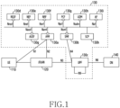
- FIG. 1 illustrates a wireless communication system according to various embodiments of the present disclosure.
- the system includes a user equipment (UE) 100, a radio access network (RAN) 120, a core network 130, and a data network (DN) 140.
- the core network 130 includes an access and mobility management function (AMF) 130a, a session management function (SMF) 130b, a user plane function (UPF) 130c, a network slice selection function (NSSF) 130d, a network exposure function (NEF) 130e, a network repository function (NRF) 130f, a policy control function (PCF) 130g, a unified data management (UDM) 130h, an application function (AF) 130i, an authentication server function (AUSF) 130g, and a service communication proxy (SCP)130h.
- AMF access and mobility management function
- SMF session management function
- UPF user plane function
- NSF network slice selection function
- NEF network exposure function
- NRF network repository function
- PCF policy control function
- UDM unified data management
- AF application function
- AUSF authentication server function
- the UE 110 is a device used by a user, and communicates with a base station included in the RAN 120 over a radio channel. Besides the UE, the UE 110 may be referred to as a 'terminal', a ⁇ mobile station', a 'subscriber station', a 'remote terminal', a ⁇ wireless terminal', a ⁇ user device' or other term having technically equivalent meaning.
- the RAN 120 is a network directly connected to a user device (e.g., the UE 110), and is an infrastructure which provides radio access to the UE 110.
- the RAN 120 includes a set of a plurality of base stations, and the plurality of the base stations may perform communication through an interface formed therebetween. At least some of the interfaces between the plurality of the base stations may be wired or wireless.
- the base station may have a structure divided into a central unit (CU) and a distributed unit (DU). In this case, one CU may control a plurality of DUs.
- the base station may be referred to as an ⁇ access point (AP)', an ⁇ eNodeB (eNB)', a '5 th generation (5G) node', a 'next generation node B (gNB)', a ⁇ wireless point', a 'transmission/reception point (TRP)' or other term having the technically identical meaning.
- AP access point
- eNB ⁇ eNodeB
- 5G 5 th generation node B
- gNB 'next generation node B
- TRP 'transmission/reception point
- the core network 130 which is a network which manages the whole system, controls the RAN 120 and processes data and control signals for the UE 110 transmitted and received via the RAN 120.
- the core network 130 performs various functions such as user plane and control plane control, mobility processing, subscriber information management, charging, and interworking with other system (e.g., a long term evolution (LTE) system).
- LTE long term evolution
- the core network 130 may include a plurality of devices functionally separated with different NFs.
- the NFs e.g., the SMF 130b, the UPF 130c, etc.
- Logical entities may be implemented with a processor, hardware, firmware, or a combination thereof. Each logical entity may be provided by one device or a plurality of devices.
- the AMF 130a is an NF which manages radio network access and mobility for the UE.
- the SMF 130b is an NF which manages a session for the UE.
- the session information includes quality of service (QoS) information, charging information, and packet processing information.
- the UPF 130c is an NF which processes user plane traffic, that is, packets transmitted and received by a customer over a communication network.
- the UPF 130c may be controlled by the SMF 130b.
- the system may include an unstructured data storage network function (UDSF).
- the UDSF is an NF which stores unstructured data, and may store or retrieve data of any type at a request of the NF.
- one of the structural features of the communication network separates the control plane for services such as AMF and SMF and the user plane for processing actual traffic.
- the user traffic processing supported by the UPF that is, the packet processing may be divided into various detailed processing functions as shown in the following [Table 1].
- [Table 1] Function Description Basic packet processing GTP-U (general packet radio system (GPRS) tunneling protocol-user plane) tunneling management, packet transmission between next generation radio access network (NG-RAN) and data network (DN) Packet detection A function of UPF to classify packets to process the packets.
- GPRS general packet radio system
- NG-RAN next generation radio access network
- DN data network
- QoS enforcement A function of service quality control: Bit rate adjustment; Packet gating, which discards packets or suspends transmission; Flow marking that adds information about the identified flow to the packet as a result of packet detection; Add identified service type to packet, Add service class indicator (SCI) Usage reporting) A function to record and report traffic usage/information such as traffic volume, duration, and event. Includes support function for billing.
- Packet buffering A function of buffering packets for a specific terminal and reporting status information on packet arrival Multi-access supporting A function that supports simultaneous interworking of several types of access networks (eg 5G and 4G, 5G and WiFi, etc.) DPI(deep packet inspection) A function to analyze the packet in detail and identify what kind of service/content it is.
- the usage report function may additionally exist for other functions. That is, the usage reporting function may be added to other function which requires result reporting. For example, the usage report function may be performed together with the packet buffering function and the DPI function.
- one packet processing function or module may be referred to as a ⁇ UPF service'.
- the UPF service may be understood to correspond to each of the various packet processing detailed functions described above.
- the QoS enforcement function corresponds to the UPF ⁇ QoS enforcement service'.
- additional packet processing functions other than the above-described various packet processing detailed functions, for example, a network address translation (NAT) function, a virtual local area network (LAN) support function, and so on may be further supported.
- NAT network address translation
- LAN virtual local area network
- One UPF instance may support one or more UPF services. If each UPF service is implemented in the form of an identifiable instance, the UPF service may be referred to as a ⁇ UPF service instance'.
- UPF service instances providing the same service may be grouped into a UPF service set.
- UPF service instances belonging to one UPF service set may exchange or share context with each other, and provide the same service.
- the UPF instances providing the same service may together construct the UPF set, and UPF instances belonging to one UPF set may exchange or share context and provide the same service.
- service continuity for the UE or IP address preservation may be supported between the UPF instances belonging to the same UPF service set or the UPF set.
- the UPF instance may be identified by realizing the UPF which is the NF defined in the 3GPP standard. That is, the UPF instance may be understood as a hardware device implemented to perform a calculation for at least one UPF service and to transmit and receive information. Alternatively, the UPF instance may be understood as an instance or a process of software executed on a physical hardware device in a virtualized system. In this case, it may be understood that the UPF instance operates as a device (e.g., a virtual machine) equivalent to a hardware device in terms of functionality or interworking with an external device. Accordingly, the UPF instance may be referred to as a ⁇ UPF device' or a ⁇ UPF node'.
- the UPF device or the UPF node may be understood as an instance in the virtualized system.
- One UPF may support one or more UPF services, and may be separated and implemented as at least one UPF service instance of the identifiable form, by realizing each of the UPF services. If the UPF is implemented as the UPF instance, the UPF service instance may be included in the UPF instance.
- terms such as 'UPF', ⁇ UPF instance', ⁇ UPF service instance', ⁇ UPF device', and ⁇ UPF node' may be used interchangeably.
- a target detected and matched for a specific packet is expressed as a flow.
- the flow may be used not only as a service data flow indicating a data flow for a specific service, but also as an expression indicating a specific service application.
- FIG. 2 illustrates a configuration of a core network device in a wireless communication system according to various embodiments of the present disclosure.
- the structure illustrated in FIG. 2 may be understood as a configuration of a device for providing at least one of the AMF, the UPF, the NSSF, the NEF, the NRF, the NCF, the UDM, the AF, the AUSF, the SMF, and the SCP of FIG. 1 or one function or service of a plurality of instances separated from them.
- a term such as ⁇ ...unit' or ⁇ ... er' used hereafter indicates a unit for processing at least one function or operation, and may be implemented using hardware, software, or a combination of hardware and software.
- the core network device includes a communication unit 210, a storage unit 220, and a control unit 230.
- the communication unit 210 provides an interface for communicating with other devices in the network. That is, the communication unit 210 converts a bit stream transmitted from the core network device to other device into a physical signal, and converts a physical signal received from other device into a bit stream. That is, the communication unit 210 may transmit and receive signals. Accordingly, the communication unit 210 may be referred to as a modem, a transmitter, a receiver, or a transceiver. In this case, the communication unit 210 enables the core network device to communicate with other devices or systems via a backhaul connection (e.g., wired backhaul or wireless backhaul) or over the network.
- a backhaul connection e.g., wired backhaul or wireless backhaul
- the storage unit 220 stores data such as a basic program, an application program, and setting information for the operation of the core network device.
- the storage unit 220 may include a volatile memory, a nonvolatile memory or a combination of a volatile memory and a nonvolatile memory.
- the storage unit 220 provides the stored data at a request of the control unit 230.
- the control unit 230 controls general operations of the core network device. For example, the control unit 230 transmits and receives signals through the communication unit 210. In addition, the control unit 230 invokes and executes a command stored in the storage unit 220, and records and reads data. For doing so, the control unit 230 may include at least one processor. According to various embodiments, the control unit 230 may control the core network device to perform operations according to various embodiments to be described.
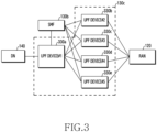
- FIG. 3 illustrates an example of a UPF connection structure in a wireless communication system according to various embodiments of the present disclosure.
- FIG. 3 illustrates the structure in which the UPF 130c is divided into a plurality of UPF services 330a through 330e.
- the plurality of the UPF services 330a through 330e illustrated in FIG. 3 may be understood as a plurality of UPF instances or devices.
- the UPF 130a is connected to the RAN 120, the SMF 130b, and the DN 140, and includes the plurality of the UPF services 330a through 330e.
- the UPF 130a processes user traffic between the DN 140 and the RAN 120.
- the UPF 130a performs the packet processing function such as QoS control, usage reporting such as charging, and packet buffering.
- the whole packet processing process is supported by a network of the UPF services 330a through 330e having different functions. For example, if a specific service data flow needs the charging, the DPI, and the QoS control, traffic belonging to the corresponding service may be processed by the UPF services 330a through 330e which provide the corresponding function and are logically divided.
- specific UPF operations such as a type of the packet processing performed by the UPF services 330a through 330e and a path for forwarding the processed packet may be controlled by a rule forwarded by the SMF 130b.
- a process of processing the packet at the plurality of the separated UPF services 330a through 330e may be largely divided into two steps as follows.
- the first step is to perform packet detection/mapping.
- the UPF receiving the packet classifies the packet according to a set packet detection rule, and maps the packet to the flow according to the classification result. That is, the packet detection may be understood as mapping a corresponding packet to a specific flow, using information of the specific packet. In so doing, the flow may be a service data flow for the service-based control.
- the second step is to perform the packet processing.
- the UPF receiving the packet processes the packet according to a set action rule.
- the action which the UPF may perform may include at least one of the QoS enforcement, the packet buffering, the usage report, and the forward according to characteristics. If low mapping information is obtained through the first step and the action rule to perform for each flow is obtained, the UPF may perform the flow-based action without separate packet detection/mapping. If there is no mapping information for each flow, or if the UPF has a separate packet detection rule and its associated action rule, the UPF may perform the packet detection/mapping to distinguish a target for the action.
- specific packets and flows may be repeatedly processed through the first step and the second step, or may be processed by various combinations. For example, after passing through the first step once, actions of different types may be sequentially performed in the second step.
- the UPF may be divided into the plurality of the entities.
- FIG. 3 illustrates that the UPF is divided based on the packet processing function or service.
- the UPF may be divided based on a different criterion.
- the UPF may be divided based on a computation amount.
- a plurality of entities performing the corresponding function may be defined.
- the UPF may be divided based on the application or the service (a service provided to the user other than the UPF service). Since a function combination required on the UPF may differ according to the type of the application or the service, the UPF may be divided such that each entity or entity subset has at least one function required for a specific application.
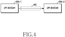
- FIG. 4 illustrates an example of a packet forwarding scheme in a wireless communication system according to various embodiments of the present disclosure.
- FIG. 4 illustrates the packet forwarding using a tunnel.
- a UPF device #1 430c-1 and a UPF device #2 430c-2 connected to each other may transmit and receive a packet.
- the UPF device # 1 430c-1 performs the packet detection, and is to forward the packet to the UPF device #2 430c-2 as a result of the packet detection, that is, together with flow information
- a method of forwarding the flow information which is the detection result to the UPF device #2 430c-2 is required.
- a tunnel 402 is established for each specific flow, and packets belonging to the corresponding flow are forwarded through the corresponding tunnel 402.
- the flow information (e.g., a flow identifier) may be included in a header of the packet forwarded through the tunnel 402 established between the UPF device #1 430c-1 and the UPF device #2 430c-2.
- the UPF device #1 430c-1 may indicate the flow through the tunnel identifier.
- a rule for taking an action for a specific flow may be set at the UPF device #2 430c-2.
- the UPF device #2 430c-2 does not perform separate packet detection using the received flow information, and processes the packet according to the corresponding action rule. This procedure may be applied even if a plurality of packet processing actions is required.
- one UPF may support two or more packet processing functions (e.g., UPF services), the corresponding UPF may perform two or more packet processing operations using the received flow information. If two or more packet processing functions are supported in two or more UPFs separately, the UPFs may be sequentially connected and perform the respective packet processing operations. In this case, a scheme of expressing the flow information using the above-described tunnel may be adopted.
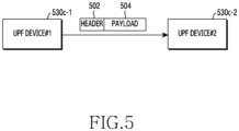
- FIG. 5 illustrates another example of a packet forwarding scheme in a wireless communication system according to various embodiments of the present disclosure.
- FIG. 5 illustrates the packet forwarding using a header.
- flow information which is a packet detection result is included in a header 502 of a packet transmitted between a UPF device #1 530c-1 and a UPF device #2 530c-2.
- the packet includes the header 502 and a payload 504, and the header 502 may include the flow information. That is, in the present embodiment, the flow information obtained by the packet detection is forwarded without separate tunneling.
- the flow information may be forwarded to a next UPF by being inserted into an IP header or a layer 2 (L2) header. If using the IP header, the flow information may be forwarded through a DSCP field, a traffic class or a flow label field. If using the L2 header, the flow information may be forwarded through a tag field or an etherType field. For doing so, while the UPF device #1 530c-1 and the UPF device #2 530c-2 generate a PDU session, information of how to forward the flow information and flow identifier information may be exchanged.
- L2 layer 2
- the rule for taking action for a specific flow may be set in the UPF device #2 430c-2.
- the UPF device #2 430c-2 does not perform separate packet detection using the received flow information, and processes the packet according to the corresponding action rule. This procedure may be applied even if a plurality of packet processing actions is required.
- one UPF may support two or more packet processing functions (e.g., UPF services), the corresponding UPF may perform two or more packet processing operations using the received flow information. If two or more packet processing functions are supported separately by two or more UPFs, the UPFs may be sequentially connected and perform the respective packet processing operations. In this case, the scheme of expressing the flow information using the above-described tunnel may be employed.
- the flow information between two UPF devices may be identified by the information included in the used tunnel or header. If a plurality of UPF services is provided by one UPF device, that is, one UPF instance, the flow information exchange between the UPF services may be forwarded using an internal function (e.g., an application program interface (API)). For example, the flow information may be indicated using at least one parameter used by the API.
- API application program interface
- FIG. 6 illustrates an example of packet processing in a wireless communication system according to various embodiments of the present disclosure.
- FIG. 6 illustrates the packet forwarding using the header.
- FIG. 6 illustrates input and output operations for a specific UPF to provide the UPF service, that is, the service for the packet processing.
- the horizontal axis represents the user plane
- the vertical axis represents the control plane.
- the control plane is a region where the UPF receives the rule for the packet processing, or exchanges information through an interface for forwarding specific information, and may correspond to is an N4 reference point between the SMF and the UPF.
- the user plane may correspond to N3 associated with the NG-RAN, N9 associated with other UPF, and N6 reference point associated with the DN.
- a UPF service 630 performs an operation of processing a packet of which the packet detection is completed.
- the UPF service 630 receives rule information for the packet processing from the SMF.
- the rule may include a relationship between a flow identifier for identifying a packet for the packet processing, and an action indicating the packet processing operation. If actions of different types need to be set, the rule information received by the UPF service 630 may be classified per action. For example, if the UPF service 630 performs the QoS enforcement and the usage reporting, information of a QoS enforcement rule (QER) and a usage reporting rule (URR) may be received. As another example, if the UPF service 630 processes a packet and then needs to forward the packet to other entity, forwarding action rule (FAR) information may be received.
- QER QoS enforcement rule
- URR usage reporting rule
- FAR forwarding action rule
- the rule received by the service 630 from the SMF may include identifier(s) for flows mapped to target packets.
- the rule information may include order or priority information by which various rules received by the UPF service 630 are applied. If no action rule is explicitly matched and an action rule basically performed is required, the action basically performed may be set or received for any packet or flow with the lowest priority.
- the UPF service 630 receives an actual user data packet through a path on the user plane.
- the UPF service 630 may identify the flow corresponding to the received packet without a separate packet detection operation, based on the tunnel of the received packet, or based on the flow identifier included in the packet header.
- the UPF service 630 identifies whether there is the action rule corresponding to the flow identifier according to priority, performs the action if there is the mapped action, and repeats identifying and performing operation until there are no more action rules to be matched.
- the UPF service 630 collects/processes data to report according to the set reporting rule, and reports corresponding information if the reporting condition is satisfied. If the action rule for the packet processing is to forward the packet to other entity, the UPF service 630 sets destination and header information according to the FAR, and forwards the packet to another UPF service, the DN or the RAN.
- specific information e.g., charging, usage, etc.
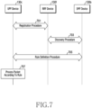
- FIG. 7 illustrates an example of a signal exchange diagram for processing a packet in a wireless communication system according to various embodiments of the present disclosure.
- the UPF device 130c performs a registration procedure with the NRF device 130f.
- the UPF device 103c transmits information of the UPF service provided by the UPF device 103c to the NRF device 103f.
- the NRF device 130f may identify the presence of the UPF device 130c and the UPF information which may be provided by the UPF device 130c, and register information of the UPF device 130c.
- the SMF device 130b performs a discovery procedure with the NRF device.
- the discovery procedure includes operations for the SMF device 130b to identify at least one UPF device, that is, UPF instance which provides at least one UPF service required for processing a packet of the UE.
- the SMF device 130b may obtain at least one UPF device information required to process packets on a flow corresponding to a specific session of the UE.
- the UPF device 130c and the SMF device 130b perform a rule definition procedure.
- the rule definition procedure includes operations for the SFM device 130b to generate a rule and forward the generated rule to the UPF device 130c.
- rule information forwarded from the SMF device 130b to the UPF device 130c may be all or part of the rule.
- the UPF device 130c processes the packet according to the rule.
- the UPF device 130c may identify the UPF service and detailed rules to be performed by the UPF device 130c, based on the rule information received from the SMF device 130b, and process the packet according to the identified rules.
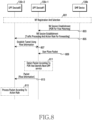
- FIG. 8 illustrates an example of a signal exchange diagram if a packet is forwarded using tunneling in a wireless communication system according to various embodiments of the present disclosure.
- FIG. 8 illustrates that two packet processing functions, that is, UPF services (e.g., packet detection, additional action) are performed. However, a procedure described below may be applied even if three or more packet processing functions are performed.
- UPF services e.g., packet detection, additional action
- a UPF device #1 130c-1 and a UPF device #2 130c-2 may register UPF service related information to an NRF device, and an SMF device 130b may perform an operation for selecting UPFs to process traffic for a specific service.
- the SMF device 130b transmits an N4 session establishment message to the UPF device #1 130c-1.
- the SMF device 130b forwards an N4 (PFCP) rule for specifically controlling the packet processing operation to be performed by the UPF device #1 130c-1.
- the N4 rule forwarding operation may be performed as part of a PDU session establishment process for a specific UE and a specific service (DNN).
- DNN specific service
- the UPF device #1 130c-1 detects a packet and forwards the matched flow information to another UPF device, and accordingly the rule forwarded by the SMF device 130b includes a packet detection rule (PDR).
- PDR packet detection rule
- the PDR includes one or more packet detection information (PDI) to be used for the packet detection, and may further include information for identifying the flow to which the matched packet belongs.
- the flow identification information may include a flow identifier to be included in the header or tunnel information to which the packet belongs.
- the FAR including a detailed rule for forwarding the packet to a next UPF device are included.
- the PDR may not directly include the identifier for the matched flow, but includes a corresponding FAR ID for the packet detection result.
- the FAR should include information for identifying the flow, the packet may be forwarded according to the FAR corresponding to the packet after the packet detection, and the flow identification information may be added.
- the SMF device 130b transmits an N4 session establishment message to the UPF device #2 130c-1.
- the SMF device 130b forwards the N4 (PFCP) rule for specifically controlling the packet processing operation to be performed by the UPF device #2 130c-2.
- the N4 rule forwarding operation may be performed as part of the PDU session establishment process for a specific UE and a specific service (DNN).
- DNN specific service
- the UPF device #2 130c-2 performs a specific action and forwards the processed packet to other entity, and accordingly the rule forwarded by the SMF device 130b includes the action rule for this.
- the action rule includes detailed parameters describing a specific packet processing operation, and may include a flow identifier for a target to be processed.
- the UPF device #1 130c-1 and the UPF device #2 130c-2 establish a tunnel. That is, if it is necessary to generate a separate tunnel or association, the UPF device #1 130c-1 and the UPF device #2 130c-2 may transmit and receive messages for the tunnel establishment.
- the tunnel establishment may be performed by direct signaling between the UPF device #1 130c-1 and the UPF device #2 130c-2, or may be carried out through the SMF device 130b.
- the UPF device #1 130c-1 receives a user plane packet from the associated object.
- the object forwarding the packet to the UPF device #1 130c-1 may be the RAN, the DN, or other UPF device.
- the received packet may include uplink data or downlink data.
- the UPF device #1 130c-1 performs the packet detection and the flow matching on the received packet. If a plurality of PDRs is set, the UPF device #1 130c-1 determines whether there is the matching PDR according to the priority. If the packet is matched for the PDI of the PDR, the UPF device #1 130c-1 allows other UPF to identify the flow using this if the PDR includes the flow information, or may perform the packet processing using the corresponding action rule if the PDR includes an ID of other associated action rule without the flow information. If the flow information is included in the action rule, the UPF device #1 130c-1 may allow other UPF to identify the flow using this.
- the UPF device #1 130c-1 forwards the packet to a next UPF device the UPF device #2 130c-2. At this time, the UPF device #1 130c-1 forwards the flow information together so that the UPF device #2 130c-2 obtains the packet detection result.
- the flow information may be forwarded explicitly or implicitly. For example, the packet may be forwarded through a specific tunnel generated for each flow.
- the UPF device #2 130c-2 processes the received packet. Specifically, the UPF device #2 130c-2 identifies the flow of the packet received from the UPF device #1 130c-1, and uses this to identify the action rule to be performed on the corresponding flow. If a plurality of action rules is set at the UPF device #2 130c-2, the UPF device #2 130c-2 identifies the action rule applicable to the corresponding flow according to the priority.
- the action rule may include configuration for performing one action type only once in one flow, not to generate duplicate actions for the same flow, or configuration allowing to apply the same action type to one flow multiple times with different detailed parameters depending on the service type and action characteristics.
- the action type indicates the type of the packet processing service which may be provided by the UPF such as QoS enforcement, forwarding, buffering, and usage reporting.
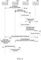
- FIG. 9 illustrates an example of a signal exchange diagram if a packet is forwarded using a header in a wireless communication system according to various embodiments of the present disclosure.
- FIG. 9 illustrates that two packet processing functions, that is, UPF services (e.g., packet detection, additional action) are conducted. However, a procedure described below may be applied even if three or more packet processing functions are performed.
- UPF services e.g., packet detection, additional action
- a UPF device #1 130c-1 and a UPF device #2 130c-2 each perform the NF registration procedure with an NRF device 130f.
- the UPF device #1 130c-1 and the UPF device #2 130c-2 each may forward NF profile and association information (e.g., peer information) to the NRF device 130f through the NF registration procedure.
- the NF profile may include information of a function (e.g., UPF service) and a maximum capacity supported by each of the UPF device #1 130c-1 and the UPF device #2 130c-2.
- the association information may include information of other network entity (e.g., another UPF device, the RAN, or the DN) for interworking with itself.
- the NRF device 130f stores information received from the UPF device #1 130c-1 and the UPF device #2 130c-2.
- the SMF device 130b transmits an NF discovery request message for selecting at least one UPF device to the NRF device 130f. If the SMF device 130b stores sufficient information to select the UPF device or has already performed the UPF discovery procedure, the step 905 may be omitted.
- the NR discovery request message may include information of UPF services, that is, UPF functions required by the SMF device 130b for a specific application, service, or traffic.
- the NRF device 130f determines at least one UPF device according to a request of the SMF device 130b.
- the set of at least one UPF device may be referred to as a ⁇ UPF network'.
- the NRF device 130f transmits a UPF discovery response message including information of at least one selected UPF device to the SMF device 130b.
- the UPF discovery response message may include a candidate group of at least one UPF device for supporting the packet processing service requested by the SMF and association information between the UPF devices.
- the SMF device 130b selects UPF devices using the received information, the stored information, and configuration information, and generates an N4 (PFCP) rule for controlling each UPF.
- PFCP PFCP
- the SMF device 130b transmits an N4 session establishment message to the UPF device #1 130c-1.
- the N4 session establishment message includes a rule for the packet processing.
- the rule forwarded to the UPF device #1 130c-1 includes the PDR, and further includes other action rule (namely FAR, etc.) depending on whether to process an additional packet or the flow identifier determination.
- the SMF device 130b transmits an N4 session establishment message to the UPF device #2 130c-2.
- the N4 session establishment message includes the packet processing rule.
- the UPF device #2 130c-2 performs an action following the packet detection result performed by the UPF device #1 130c-1
- the N4 rule forwarded to the UPF device #2 130c-2 may include the rule including the detailed action and an identifier for a target flow.
- the UPF device #1 130c-1 performs the packet detection and the flow matching on the received packet. If a plurality of PDRs is set, the UPF device #1 130c-1 determines whether there is the matching PDR according to priority. If the packet is matched for the PDI of the PDR, if the PDR includes flow information, the UPF device #1 130c-1 may allow other UPF to identify the flow using this, or may process the packet using the corresponding action rule if the PDR includes an ID of other associated action rule without the flow information. If the flow information is included in the action rule, the UPF device #1 130c-1 may allow other UPF to identify the flow using this.
- the UPF device #1 130c-1 forwards the packet to the UPF device #2 130c-2 which is a next UPF device. At this time, the UPF device #1 130c-1 forwards the flow information together so that the UPF device #2 130c-2 obtains the packet detection result.
- the flow information may be forwarded explicitly or implicitly. For example, the flow information may be included in the header of the packet.
- the UPF device #2 130c-2 processes the received packet. Specifically, the UPF device #2 130c-2 identifies the flow of the packet received from the UPF device #1 130c-1, and uses this to identify the action rule to be performed on the corresponding flow. If a plurality of action rules is set at the UPF device #2 130c-2, the UPF device #2 130c-2 identifies the action rule applicable to the corresponding flow according to the priority.
- the action rule may include configuration for performing one action type only once in one flow, not to generate duplicate actions for the same flow, or configuration allowing to apply the same action type to one flow multiple times with different detailed parameters depending on the service type and action characteristics.
- the action type indicates the type of the packet processing service which may be provided by the UPF such as QoS enforcement, forwarding, buffering, and usage reporting.
- the NRF device 130f stores and provides information.
- the NRF device 130f may be replaced with an SCP device.
- the UPF device #1 130c-1 and the UPF device #2 130c-2 may perform the NR registration procedure with the SCP device in step 901 and step 903
- the SMF device 130b may perform the UPF discovery procedure with the SCP device, in step 907 and step 911.
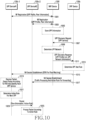
- FIG. 10 illustrates yet another example of a signal exchange diagram if some rule is defined by a UPF device in a wireless communication system according to various embodiments of the present disclosure.
- FIG. 10 illustrates that two packet processing functions, that is, UPF services (e.g., packet detection, additional action) are conducted. However, a procedure described below may be applied even if three or more packet processing functions are performed.
- UPF services e.g., packet detection, additional action
- a UPF device #1 130c-1 and a UPF device #2 130c-2 each perform the NF registration procedure with an NRF device 130f.
- the UPF device #1 130c-1 and the UPF device #2 130c-2 each may forward NF profile and association information (e.g., peer information) to the NRF device 130f through the NF registration procedure.
- the NF profile may include information of a function (e.g., UPF service) and a maximum capacity supported by each of the UPF device #1 130c-1 and the UPF device #2 130c-2.
- the association information may include information of other network entity (e.g., another UPF device, the RAN, or the DN) for interworking with itself.
- the NRF device 130f stores information received from the UPF device #1 130c-1 and the UPF device #2 130c-2.
- the SMF device 130b transmits an NF discovery request message for selecting at least one UPF device to the NRF device 130f. If the SMF device 130b stores sufficient information to select the UPF device or has already performed the UPF discovery procedure, step 905 may be omitted.
- the NR discovery request message may include information of UPF services, that is, UPF functions required by the SMF device 130b for a specific application, service, or traffic.
- the NRF device 130f determines at least one UPF device according to a request of the SMF device 130b.
- the set of at least one UPF device may be referred to as a ⁇ UPF network'.
- the NRF device 130f transmits a UPF discovery response message including information of at least one selected UPF device to the SMF device 130b.
- the UPF discovery response message may include a candidate group of at least one UPF device for supporting the packet processing service requested by the SMF and association information between the UPF devices.
- the SMF device 130b selects UPF devices using the received information, the stored information, and configuration information, and generates an N4 (PFCP) rule for controlling the UPF devices.
- the rule forwarded to the UPF device #1 130c-1 may include not only the rules used by the UPF device #1 130c-1, but also all or part of the rule for the UPF device #2 130c-2 for receiving the packet processed by the UPF device #1 130c-1 and processing a subsequent action.
- the SMF device 130b transmits an N4 session establishment message to the UPF device #1 130c-1.
- the N4 session establishment message includes a rule for the packet processing.
- the rule forwarded to the UPF device #1 130c-1 includes the PDR, and may further include other action rule (e.g., FAR, etc.) depending on whether to process an additional packet or the flow identifier determination.
- the SMF device 130b transmits an N4 session establishment message to the UPF device #2 130c-2.
- the N4 session establishment message includes the packet processing rule.
- the UPF device #2 130c-2 performs an action following the packet detection result performed by the UPF device #1 130c-1
- the N4 rule forwarded to the UPF device #2 130c-2 may include the rule including the detailed action and an identifier for a target flow.
- the UPF device #1 130c-1 performs the packet detection and the flow matching on the received packet, and then identifies a next UPF service.
- the UPF device #1 130c-1 determines an action rule for the next UPF, that is, the UPF device #2 130c-2.
- the action rule determined by the UPF device #1 130c-1 is a rule which may be used together with the action rule of the UPF device #2 130c-2 provided from the SMF device 130b. That is, the UPF device #1 130c-1 may determine at least part of the detailed parameter or the action rule to be used by the UPF device #2 130c-2 to process a packet.
- the UPF device #1 130c-1 forwards the packet to the UPF device #2 130c-2 which is the next UPF device.
- the UPF device #1 130c-1 forwards the flow information together so that the UPF device #2 130c-2 obtains the packet detection result.
- the flow information may be forwarded explicitly or implicitly.
- the flow information may be included in the header of the packet.
- the packet may include information of at least part of the detailed parameter or the action rule to be used by the UPF device #2 130c-2 to process the packet.
- the action rule information included in the packet may include an indicator indicating one of predefined rules, and information for changing a transmission path.
- the UPF device #2 130c-2 processes the received packet.
- the UPF device #2 130c-2 may process the packet using the action rule received or preset from the SMF device 130b and the flow information received from the UPF device #1 130c-1. If the UPF device #1 130c-1 forwards not only the flow information but also the rule or the detailed parameter for the packet processing, the UPF device #2 130c-2 may process the packet based on the rule provided by the UPF device #1 130c-1. If the action rule received or preset from the SMF device 130b conflicts with the rule provided from the UPF device #1 130c-1, the rule to apply first may differ depending on the UPF setting.
- a computer-readable storage medium storing one or more programs (software modules) may be provided.
- One or more programs stored in the computer-readable storage medium may be configured for execution by one or more processors of an electronic device.
- One or more programs may include instructions for controlling the electronic device to execute the methods according to the embodiments described in the claims or the specification of the present disclosure.
- Such a program may be stored to a random access memory, a nonvolatile memory including a flash memory, a read only memory (ROM), an electrically erasable programmable ROM (EEPROM), a magnetic disc storage device, a compact disc (CD)-ROM, digital versatile discs (DVDs) or other optical storage devices, and a magnetic cassette. Alternatively, it may be stored to a memory combining some or all of those recording media. A plurality of memories may be included.
- the program may be stored in an attachable storage device accessible via a communication network such as Internet, Intranet, LAN, wide LAN (WLAN), or storage area network (SAN), or a communication network by combining these networks.
- a storage device may access a device which executes an embodiment of the present disclosure through an external port.
- a separate storage device on the communication network may access the device which executes an embodiment of the present disclosure.
- the elements included in the invention are expressed in a singular or plural form.
- the singular or plural expression is appropriately selected according to a proposed situation for the convenience of explanation, the present disclosure is not limited to a single element or a plurality of elements, the elements expressed in the plural form may be configured as a single element, and the elements expressed in the singular form may be configured as a plurality of elements.
- the present disclosure generally relates to a wireless communication system, and more particularly, to an apparatus and methods for processing traffic in the wireless communication system.
Landscapes
- Engineering & Computer Science (AREA)
- Computer Networks & Wireless Communication (AREA)
- Signal Processing (AREA)
- Databases & Information Systems (AREA)
- Mobile Radio Communication Systems (AREA)
Applications Claiming Priority (2)
| Application Number | Priority Date | Filing Date | Title |
|---|---|---|---|
| KR1020190113071A KR102808487B1 (ko) | 2019-09-11 | 2019-09-11 | 무선 통신 시스템에서 트래픽을 처리하기 위한 장치 및 방법 |
| PCT/KR2020/012287 WO2021049899A1 (ko) | 2019-09-11 | 2020-09-11 | 무선 통신 시스템에서 트래픽을 처리하기 위한 장치 및 방법 |
Publications (3)
| Publication Number | Publication Date |
|---|---|
| EP4024788A1 EP4024788A1 (en) | 2022-07-06 |
| EP4024788A4 EP4024788A4 (en) | 2022-09-14 |
| EP4024788B1 true EP4024788B1 (en) | 2024-11-06 |
Family
ID=74866761
Family Applications (1)
| Application Number | Title | Priority Date | Filing Date |
|---|---|---|---|
| EP20863331.3A Active EP4024788B1 (en) | 2019-09-11 | 2020-09-11 | Device and methods for processing traffic in wireless communication system |
Country Status (5)
| Country | Link |
|---|---|
| US (1) | US12081439B2 (ko) |
| EP (1) | EP4024788B1 (ko) |
| KR (1) | KR102808487B1 (ko) |
| CN (1) | CN114586409B (ko) |
| WO (1) | WO2021049899A1 (ko) |
Families Citing this family (5)
| Publication number | Priority date | Publication date | Assignee | Title |
|---|---|---|---|---|
| CN110582993B (zh) * | 2017-05-09 | 2021-11-12 | 诺基亚通信公司 | 通过局域网连接进行通信的方法和装置 |
| KR20220019567A (ko) | 2020-08-10 | 2022-02-17 | 삼성전자주식회사 | 무선 통신 시스템의 안정성을 높이는 방법 및 장치 |
| ES3043435T3 (en) * | 2021-06-08 | 2025-11-25 | Koninklijke Kpn Nv | System and method for establishing a dual-layer pdu session |
| KR20240030551A (ko) * | 2022-08-31 | 2024-03-07 | 삼성전자주식회사 | 통신 시스템에서 트래픽 오프로딩을 위한 방법 및 장치 |
| KR20250090059A (ko) * | 2023-12-12 | 2025-06-19 | 삼성전자주식회사 | 무선 통신 시스템에서 NF (network function)가 통신을 수행하는 방법 및 장치 |
Family Cites Families (20)
| Publication number | Priority date | Publication date | Assignee | Title |
|---|---|---|---|---|
| JP6679751B2 (ja) * | 2016-04-01 | 2020-04-15 | アイディーエーシー ホールディングス インコーポレイテッド | サービススライス選択および分離のための方法 |
| EP4496287A3 (en) | 2017-05-09 | 2025-04-02 | Huawei Technologies Co., Ltd. | Qos control method and device |
| KR102510545B1 (ko) * | 2017-07-03 | 2023-03-16 | 한국전자통신연구원 | 5g 네트워크 등록 방법 및 pdu 세션 앵커 재배치하는 방법 |
| US10757611B2 (en) * | 2017-09-22 | 2020-08-25 | Ofinno, Llc | SMF and AMF relocation during UE registration |
| US20190116546A1 (en) | 2017-10-17 | 2019-04-18 | Electronics And Telecommunications Research Institute | Method for notifying downlink data in a network, network triggered service request method, and network entity performing the same |
| KR20190043079A (ko) * | 2017-10-17 | 2019-04-25 | 한국전자통신연구원 | 네트워크에서 하향링크 데이터를 알리는 방법, 네트워크 트리거된 서비스 요청 방법, 그리고 이를 수행하는 네트워크 엔터티 |
| KR102106778B1 (ko) * | 2017-10-31 | 2020-05-28 | 에스케이텔레콤 주식회사 | 데이터 송수신장치 및 데이터 송수신장치의 동작 방법 |
| CN109756430B (zh) | 2017-11-07 | 2021-08-03 | 华为技术有限公司 | 一种规则的处理方法及装置 |
| US11895033B2 (en) * | 2017-11-17 | 2024-02-06 | Huawei Technologies Co., Ltd. | Method and apparatus for traffic routing and path optimization for peer-to-peer communications |
| CN110048873A (zh) * | 2018-01-16 | 2019-07-23 | 华为技术有限公司 | 多锚点协议数据单元会话的策略控制的方法和通信装置 |
| US10980084B2 (en) | 2018-02-15 | 2021-04-13 | Huawei Technologies Co., Ltd. | Supporting multiple QOS flows for unstructured PDU sessions in wireless system using non-standardized application information |
| CN113347673B (zh) * | 2018-08-13 | 2022-06-24 | 大唐移动通信设备有限公司 | Pdu会话管理、节点关联和upf发现的方法及设备 |
| US11297530B2 (en) * | 2018-11-02 | 2022-04-05 | Huawei Technologies Co., Ltd. | Method and system for using policy to handle packets |
| US10848525B2 (en) * | 2019-01-29 | 2020-11-24 | Verizon Patent And Licensing Inc. | Systems and method for selection of a user plane component for internet protocol multimedia subsystem sessions |
| WO2020167088A1 (en) | 2019-02-15 | 2020-08-20 | Samsung Electronics Co., Ltd. | Method and apparatus for transmission or reception of data in communication system |
| CN113906717B (zh) * | 2019-04-02 | 2024-01-30 | 诺基亚技术有限公司 | 本地用户平面功能控制 |
| US11330667B2 (en) * | 2019-05-03 | 2022-05-10 | Ofinno, Llc | Group communication signaling overload mitigation |
| KR102746161B1 (ko) | 2019-06-10 | 2024-12-24 | 삼성전자주식회사 | 무선 통신 시스템에서 서비스 안정성을 높이는 방법 및 장치 |
| US12238007B2 (en) * | 2019-07-03 | 2025-02-25 | Telefonaktiebolaget Lm Ericsson (Publ) | Establishing a packet forwarding control protocol session |
| CN113133079B (zh) * | 2019-12-31 | 2024-09-13 | 华为技术有限公司 | 路由配置方法及装置 |
-
2019
- 2019-09-11 KR KR1020190113071A patent/KR102808487B1/ko active Active
-
2020
- 2020-09-11 EP EP20863331.3A patent/EP4024788B1/en active Active
- 2020-09-11 US US17/642,208 patent/US12081439B2/en active Active
- 2020-09-11 WO PCT/KR2020/012287 patent/WO2021049899A1/ko not_active Ceased
- 2020-09-11 CN CN202080073826.4A patent/CN114586409B/zh active Active
Also Published As
| Publication number | Publication date |
|---|---|
| WO2021049899A1 (ko) | 2021-03-18 |
| US12081439B2 (en) | 2024-09-03 |
| CN114586409B (zh) | 2025-01-28 |
| CN114586409A (zh) | 2022-06-03 |
| EP4024788A4 (en) | 2022-09-14 |
| KR102808487B1 (ko) | 2025-05-16 |
| EP4024788A1 (en) | 2022-07-06 |
| KR20210031297A (ko) | 2021-03-19 |
| US20220321481A1 (en) | 2022-10-06 |
Similar Documents
| Publication | Publication Date | Title |
|---|---|---|
| US12075495B2 (en) | Apparatus and method for processing traffic of service in wireless communication system | |
| EP4024788B1 (en) | Device and methods for processing traffic in wireless communication system | |
| JP7834768B2 (ja) | エッジアプリケーションサーバディスカバリ方法及び装置 | |
| EP4022850B1 (en) | Apparatus and method for network automation in wireless communication system | |
| US11496581B2 (en) | Apparatus and method for supporting UPF event exposure service in wireless communication system | |
| US12238563B2 (en) | Method and device for measuring performance in wireless communication system | |
| US12328619B2 (en) | Considerations on quality of service (QOS) hints for an uplink streaming service | |
| EP3895470B1 (en) | Policy node, user plane node, control plane node and methods therein for handling quality of service in a wireless communications network | |
| US20220361038A1 (en) | Method and apparatus for managing quality of service in wireless communication system | |
| US11950299B2 (en) | Apparatus and method for handling PDU session in wireless communication system | |
| US20250203433A1 (en) | Methods, apparatus, and systems for providing information to wtru via control plane or user plane | |
| US12477445B2 (en) | Method and apparatus for supporting monitoring for external services in a wireless communication system | |
| US20250351056A1 (en) | Electronic device and method for ric query | |
| US12598244B2 (en) | Method and apparatus for transmitting data in mobile communication system | |
| EP4633105A1 (en) | Method and apparatus for supporting qos in wireless communication system | |
| KR20250121886A (ko) | 에너지 절약을 위한 정보를 송신하기 위한 전자 장치 및 방법 | |
| WO2025101027A1 (ko) | 무선 통신 시스템에서 단말의 전력 상태를 고려한 통신 제어 방법 및 장치 | |
| WO2026076171A1 (en) | Ai/ml framework to support wtru data collection over the user plane | |
| KR20240063563A (ko) | 무선 통신 시스템에서 트래픽 특성 변화에 기반하여 정보를 전달하는 방법 및 장치 | |
| CN116888946A (zh) | 边缘应用服务器发现的方法和设备 |
Legal Events
| Date | Code | Title | Description |
|---|---|---|---|
| STAA | Information on the status of an ep patent application or granted ep patent |
Free format text: STATUS: THE INTERNATIONAL PUBLICATION HAS BEEN MADE |
|
| PUAI | Public reference made under article 153(3) epc to a published international application that has entered the european phase |
Free format text: ORIGINAL CODE: 0009012 |
|
| STAA | Information on the status of an ep patent application or granted ep patent |
Free format text: STATUS: REQUEST FOR EXAMINATION WAS MADE |
|
| 17P | Request for examination filed |
Effective date: 20220331 |
|
| AK | Designated contracting states |
Kind code of ref document: A1 Designated state(s): AL AT BE BG CH CY CZ DE DK EE ES FI FR GB GR HR HU IE IS IT LI LT LU LV MC MK MT NL NO PL PT RO RS SE SI SK SM TR |
|
| A4 | Supplementary search report drawn up and despatched |
Effective date: 20220812 |
|
| RIC1 | Information provided on ipc code assigned before grant |
Ipc: H04W 8/04 20090101ALN20220808BHEP Ipc: H04L 47/2441 20220101ALN20220808BHEP Ipc: H04L 47/70 20220101ALI20220808BHEP Ipc: H04L 47/20 20220101AFI20220808BHEP |
|
| DAV | Request for validation of the european patent (deleted) | ||
| DAX | Request for extension of the european patent (deleted) | ||
| REG | Reference to a national code |
Ref country code: DE Ref legal event code: R079 Free format text: PREVIOUS MAIN CLASS: H04L0012801000 Ipc: H04L0047200000 Ref document number: 602020041024 Country of ref document: DE |
|
| GRAP | Despatch of communication of intention to grant a patent |
Free format text: ORIGINAL CODE: EPIDOSNIGR1 |
|
| STAA | Information on the status of an ep patent application or granted ep patent |
Free format text: STATUS: GRANT OF PATENT IS INTENDED |
|
| RIC1 | Information provided on ipc code assigned before grant |
Ipc: H04L 47/70 20220101ALN20240514BHEP Ipc: H04W 28/12 20090101ALI20240514BHEP Ipc: H04L 47/35 20220101ALI20240514BHEP Ipc: H04L 47/2441 20220101ALI20240514BHEP Ipc: H04L 47/20 20220101AFI20240514BHEP |
|
| RIC1 | Information provided on ipc code assigned before grant |
Ipc: H04L 47/70 20220101ALN20240528BHEP Ipc: H04W 28/12 20090101ALI20240528BHEP Ipc: H04L 47/35 20220101ALI20240528BHEP Ipc: H04L 47/2441 20220101ALI20240528BHEP Ipc: H04L 47/20 20220101AFI20240528BHEP |
|
| INTG | Intention to grant announced |
Effective date: 20240610 |
|
| GRAS | Grant fee paid |
Free format text: ORIGINAL CODE: EPIDOSNIGR3 |
|
| GRAA | (expected) grant |
Free format text: ORIGINAL CODE: 0009210 |
|
| STAA | Information on the status of an ep patent application or granted ep patent |
Free format text: STATUS: THE PATENT HAS BEEN GRANTED |
|
| AK | Designated contracting states |
Kind code of ref document: B1 Designated state(s): AL AT BE BG CH CY CZ DE DK EE ES FI FR GB GR HR HU IE IS IT LI LT LU LV MC MK MT NL NO PL PT RO RS SE SI SK SM TR |
|
| REG | Reference to a national code |
Ref country code: GB Ref legal event code: FG4D |
|
| REG | Reference to a national code |
Ref country code: CH Ref legal event code: EP |
|
| REG | Reference to a national code |
Ref country code: DE Ref legal event code: R096 Ref document number: 602020041024 Country of ref document: DE |
|
| REG | Reference to a national code |
Ref country code: IE Ref legal event code: FG4D Ref country code: NL Ref legal event code: FP |
|
| REG | Reference to a national code |
Ref country code: LT Ref legal event code: MG9D |
|
| PG25 | Lapsed in a contracting state [announced via postgrant information from national office to epo] |
Ref country code: PT Free format text: LAPSE BECAUSE OF FAILURE TO SUBMIT A TRANSLATION OF THE DESCRIPTION OR TO PAY THE FEE WITHIN THE PRESCRIBED TIME-LIMIT Effective date: 20250306 Ref country code: IS Free format text: LAPSE BECAUSE OF FAILURE TO SUBMIT A TRANSLATION OF THE DESCRIPTION OR TO PAY THE FEE WITHIN THE PRESCRIBED TIME-LIMIT Effective date: 20250306 Ref country code: HR Free format text: LAPSE BECAUSE OF FAILURE TO SUBMIT A TRANSLATION OF THE DESCRIPTION OR TO PAY THE FEE WITHIN THE PRESCRIBED TIME-LIMIT Effective date: 20241106 |
|
| PG25 | Lapsed in a contracting state [announced via postgrant information from national office to epo] |
Ref country code: FI Free format text: LAPSE BECAUSE OF FAILURE TO SUBMIT A TRANSLATION OF THE DESCRIPTION OR TO PAY THE FEE WITHIN THE PRESCRIBED TIME-LIMIT Effective date: 20241106 |
|
| REG | Reference to a national code |
Ref country code: AT Ref legal event code: MK05 Ref document number: 1740629 Country of ref document: AT Kind code of ref document: T Effective date: 20241106 |
|
| PG25 | Lapsed in a contracting state [announced via postgrant information from national office to epo] |
Ref country code: BG Free format text: LAPSE BECAUSE OF FAILURE TO SUBMIT A TRANSLATION OF THE DESCRIPTION OR TO PAY THE FEE WITHIN THE PRESCRIBED TIME-LIMIT Effective date: 20241106 |
|
| PG25 | Lapsed in a contracting state [announced via postgrant information from national office to epo] |
Ref country code: ES Free format text: LAPSE BECAUSE OF FAILURE TO SUBMIT A TRANSLATION OF THE DESCRIPTION OR TO PAY THE FEE WITHIN THE PRESCRIBED TIME-LIMIT Effective date: 20241106 |
|
| PG25 | Lapsed in a contracting state [announced via postgrant information from national office to epo] |
Ref country code: NO Free format text: LAPSE BECAUSE OF FAILURE TO SUBMIT A TRANSLATION OF THE DESCRIPTION OR TO PAY THE FEE WITHIN THE PRESCRIBED TIME-LIMIT Effective date: 20250206 |
|
| PG25 | Lapsed in a contracting state [announced via postgrant information from national office to epo] |
Ref country code: GR Free format text: LAPSE BECAUSE OF FAILURE TO SUBMIT A TRANSLATION OF THE DESCRIPTION OR TO PAY THE FEE WITHIN THE PRESCRIBED TIME-LIMIT Effective date: 20250207 Ref country code: LV Free format text: LAPSE BECAUSE OF FAILURE TO SUBMIT A TRANSLATION OF THE DESCRIPTION OR TO PAY THE FEE WITHIN THE PRESCRIBED TIME-LIMIT Effective date: 20241106 Ref country code: AT Free format text: LAPSE BECAUSE OF FAILURE TO SUBMIT A TRANSLATION OF THE DESCRIPTION OR TO PAY THE FEE WITHIN THE PRESCRIBED TIME-LIMIT Effective date: 20241106 |
|
| PG25 | Lapsed in a contracting state [announced via postgrant information from national office to epo] |
Ref country code: PL Free format text: LAPSE BECAUSE OF FAILURE TO SUBMIT A TRANSLATION OF THE DESCRIPTION OR TO PAY THE FEE WITHIN THE PRESCRIBED TIME-LIMIT Effective date: 20241106 |
|
| PG25 | Lapsed in a contracting state [announced via postgrant information from national office to epo] |
Ref country code: RS Free format text: LAPSE BECAUSE OF FAILURE TO SUBMIT A TRANSLATION OF THE DESCRIPTION OR TO PAY THE FEE WITHIN THE PRESCRIBED TIME-LIMIT Effective date: 20250206 |
|
| PG25 | Lapsed in a contracting state [announced via postgrant information from national office to epo] |
Ref country code: SM Free format text: LAPSE BECAUSE OF FAILURE TO SUBMIT A TRANSLATION OF THE DESCRIPTION OR TO PAY THE FEE WITHIN THE PRESCRIBED TIME-LIMIT Effective date: 20241106 |
|
| PG25 | Lapsed in a contracting state [announced via postgrant information from national office to epo] |
Ref country code: DK Free format text: LAPSE BECAUSE OF FAILURE TO SUBMIT A TRANSLATION OF THE DESCRIPTION OR TO PAY THE FEE WITHIN THE PRESCRIBED TIME-LIMIT Effective date: 20241106 |
|
| PG25 | Lapsed in a contracting state [announced via postgrant information from national office to epo] |
Ref country code: EE Free format text: LAPSE BECAUSE OF FAILURE TO SUBMIT A TRANSLATION OF THE DESCRIPTION OR TO PAY THE FEE WITHIN THE PRESCRIBED TIME-LIMIT Effective date: 20241106 |
|
| PG25 | Lapsed in a contracting state [announced via postgrant information from national office to epo] |
Ref country code: RO Free format text: LAPSE BECAUSE OF FAILURE TO SUBMIT A TRANSLATION OF THE DESCRIPTION OR TO PAY THE FEE WITHIN THE PRESCRIBED TIME-LIMIT Effective date: 20241106 |
|
| PG25 | Lapsed in a contracting state [announced via postgrant information from national office to epo] |
Ref country code: SK Free format text: LAPSE BECAUSE OF FAILURE TO SUBMIT A TRANSLATION OF THE DESCRIPTION OR TO PAY THE FEE WITHIN THE PRESCRIBED TIME-LIMIT Effective date: 20241106 |
|
| PG25 | Lapsed in a contracting state [announced via postgrant information from national office to epo] |
Ref country code: CZ Free format text: LAPSE BECAUSE OF FAILURE TO SUBMIT A TRANSLATION OF THE DESCRIPTION OR TO PAY THE FEE WITHIN THE PRESCRIBED TIME-LIMIT Effective date: 20241106 |
|
| PG25 | Lapsed in a contracting state [announced via postgrant information from national office to epo] |
Ref country code: IT Free format text: LAPSE BECAUSE OF FAILURE TO SUBMIT A TRANSLATION OF THE DESCRIPTION OR TO PAY THE FEE WITHIN THE PRESCRIBED TIME-LIMIT Effective date: 20241106 |
|
| REG | Reference to a national code |
Ref country code: DE Ref legal event code: R097 Ref document number: 602020041024 Country of ref document: DE |
|
| PG25 | Lapsed in a contracting state [announced via postgrant information from national office to epo] |
Ref country code: SE Free format text: LAPSE BECAUSE OF FAILURE TO SUBMIT A TRANSLATION OF THE DESCRIPTION OR TO PAY THE FEE WITHIN THE PRESCRIBED TIME-LIMIT Effective date: 20241106 |
|
| PLBE | No opposition filed within time limit |
Free format text: ORIGINAL CODE: 0009261 |
|
| STAA | Information on the status of an ep patent application or granted ep patent |
Free format text: STATUS: NO OPPOSITION FILED WITHIN TIME LIMIT |
|
| PGFP | Annual fee paid to national office [announced via postgrant information from national office to epo] |
Ref country code: NL Payment date: 20250821 Year of fee payment: 6 |
|
| PGFP | Annual fee paid to national office [announced via postgrant information from national office to epo] |
Ref country code: DE Payment date: 20250820 Year of fee payment: 6 |
|
| 26N | No opposition filed |
Effective date: 20250807 |
|
| PGFP | Annual fee paid to national office [announced via postgrant information from national office to epo] |
Ref country code: GB Payment date: 20250820 Year of fee payment: 6 |
|
| REG | Reference to a national code |
Ref country code: CH Ref legal event code: H13 Free format text: ST27 STATUS EVENT CODE: U-0-0-H10-H13 (AS PROVIDED BY THE NATIONAL OFFICE) Effective date: 20260425 |