EP4024794A1 - Procédé et appareil de détection et de mesure - Google Patents
Procédé et appareil de détection et de mesure Download PDFInfo
- Publication number
- EP4024794A1 EP4024794A1 EP20864208.2A EP20864208A EP4024794A1 EP 4024794 A1 EP4024794 A1 EP 4024794A1 EP 20864208 A EP20864208 A EP 20864208A EP 4024794 A1 EP4024794 A1 EP 4024794A1
- Authority
- EP
- European Patent Office
- Prior art keywords
- spatial mapping
- mapping matrix
- field
- frame
- indicating
- Prior art date
- Legal status (The legal status is an assumption and is not a legal conclusion. Google has not performed a legal analysis and makes no representation as to the accuracy of the status listed.)
- Granted
Links
Images







Classifications
-
- H—ELECTRICITY
- H04—ELECTRIC COMMUNICATION TECHNIQUE
- H04L—TRANSMISSION OF DIGITAL INFORMATION, e.g. TELEGRAPHIC COMMUNICATION
- H04L25/00—Baseband systems
- H04L25/02—Details ; arrangements for supplying electrical power along data transmission lines
- H04L25/0202—Channel estimation
-
- H—ELECTRICITY
- H04—ELECTRIC COMMUNICATION TECHNIQUE
- H04L—TRANSMISSION OF DIGITAL INFORMATION, e.g. TELEGRAPHIC COMMUNICATION
- H04L25/00—Baseband systems
- H04L25/02—Details ; arrangements for supplying electrical power along data transmission lines
- H04L25/0202—Channel estimation
- H04L25/0204—Channel estimation of multiple channels
-
- H—ELECTRICITY
- H04—ELECTRIC COMMUNICATION TECHNIQUE
- H04B—TRANSMISSION
- H04B17/00—Monitoring; Testing
- H04B17/30—Monitoring; Testing of propagation channels
- H04B17/309—Measuring or estimating channel quality parameters
-
- H—ELECTRICITY
- H04—ELECTRIC COMMUNICATION TECHNIQUE
- H04L—TRANSMISSION OF DIGITAL INFORMATION, e.g. TELEGRAPHIC COMMUNICATION
- H04L5/00—Arrangements affording multiple use of the transmission path
- H04L5/0001—Arrangements for dividing the transmission path
- H04L5/0014—Three-dimensional division
- H04L5/0023—Time-frequency-space
-
- H—ELECTRICITY
- H04—ELECTRIC COMMUNICATION TECHNIQUE
- H04L—TRANSMISSION OF DIGITAL INFORMATION, e.g. TELEGRAPHIC COMMUNICATION
- H04L5/00—Arrangements affording multiple use of the transmission path
- H04L5/0091—Signalling for the administration of the divided path, e.g. signalling of configuration information
- H04L5/0094—Indication of how sub-channels of the path are allocated
-
- H—ELECTRICITY
- H04—ELECTRIC COMMUNICATION TECHNIQUE
- H04L—TRANSMISSION OF DIGITAL INFORMATION, e.g. TELEGRAPHIC COMMUNICATION
- H04L25/00—Baseband systems
- H04L25/02—Details ; arrangements for supplying electrical power along data transmission lines
- H04L25/0202—Channel estimation
- H04L25/0224—Channel estimation using sounding signals
-
- H—ELECTRICITY
- H04—ELECTRIC COMMUNICATION TECHNIQUE
- H04L—TRANSMISSION OF DIGITAL INFORMATION, e.g. TELEGRAPHIC COMMUNICATION
- H04L5/00—Arrangements affording multiple use of the transmission path
- H04L5/003—Arrangements for allocating sub-channels of the transmission path
- H04L5/0048—Allocation of pilot signals, i.e. of signals known to the receiver
Definitions
- This application relates to the field of wireless communication, and more specifically, to a method and an apparatus for sensing measurement.
- Wi-Fi being used only for communication, and further expect to perform sensing, positioning, and the like on an ambient environment or a passive target by using Wi-Fi signals.
- sensing and positioning on the ambient environment or the passive target are implemented mainly by analyzing a channel estimation result of a Wi-Fi system.
- a transmit end device usually performs spatial mapping on space time stream data by using a spatial mapping (spatial mapping) technology.
- N STS pieces of space time stream data on each subcarrier in an orthogonal frequency division multiplexing (orthogonal frequency division multiplexing, OFDM) symbol are mapped onto N TX transmit links.
- the spatial mapping may be implemented by using a spatial mapping matrix (spatial mapping matrix) whose size is N TX x N STS .
- the spatial mapping matrix maps a complex vector whose length is N STS on each subcarrier to a complex vector whose length is N TX , each element of the vector before mapping corresponds to space time stream data, and each element of the vector after mapping corresponds to a transmit link.
- Spatial mapping is performed on both an OFDM symbol (a preamble symbol for short below) used to place a preamble (preamble) sequence and an OFDM symbol (a data symbol for short below) used to place to-be-transmitted data. That is, the spatial mapping matrix not only acts on the data symbol, but also acts on the preamble symbol.
- a receive end device estimates a channel state by using the preamble symbol. In this way, a channel estimation result obtained by the receive end device based on the preamble symbol is a comprehensive result of actual channel state information (channel state information, CSI) and spatial mapping.
- channel state information channel state information
- the actual channel state information is required for sensing, positioning, and the like on the ambient environment or the passive target.
- channel state information obtained by using the preamble symbol is not the actual channel state information. Consequently, sensing, positioning, and the like on the ambient environment or the passive target cannot be completed in the foregoing scenario.
- This application provides a method and an apparatus for sensing measurement, to eliminate impact of spatial mapping on a channel estimation result, thereby completing sensing, positioning, and like on an ambient environment or a passive target.
- an embodiment of this application provides a method for sensing measurement.
- An execution body of the method may be a first device, or a module (for example, a chip) used in the first device.
- the following provides description by using an example in which the execution body is the first device.
- the method includes: The first device receives an indication frame, where the indication frame is used for indicating a spatial mapping matrix; and the first device determines channel state information based on the spatial mapping matrix and a channel estimation result.
- the first device may be an access point (access point, AP) or a station (station, STA).
- access point access point
- STA station
- the indication frame may indicate one or more spatial mapping matrices.
- the one or more spatial mapping matrices may respectively correspond to spatial mapping matrices to be used by a transmit end device in different channel bandwidths and/or different numbers of space time streams.
- the one or more spatial mapping matrices are spatial mapping matrices from different transmit end devices.
- the spatial mapping matrix is used for mapping to-be-sent data onto a transmit link.
- the transmit end device may indicate, to the first device by using the indication frame, the spatial mapping matrix used by the transmit end device to send data to the first device.
- the first device eliminates impact of spatial mapping on the channel estimation result based on the spatial mapping matrix, to obtain actual channel state information, thereby completing sensing, positioning, and the like on an ambient environment or a passive target by using the obtained actual channel state information.
- the first device does not need to pre-store or know manufacturer and spatial mapping information of the transmit end device, and devices of different manufacturers can perform sensing measurement together.
- the indication frame includes a spatial mapping matrix field, and the spatial mapping matrix field is used for indicating the spatial mapping matrix.
- the transmit end device indicates the subsequently to-be-used spatial mapping matrix to the first device by adding the spatial mapping matrix field to the indication frame, so that the first device eliminates impact of spatial mapping on the channel estimation result based on the spatial mapping matrix, to obtain the actual channel state information, thereby completing sensing, positioning, and the like on the ambient environment or the passive target by using the obtained actual channel state information.
- the spatial mapping matrix field includes at least one of a column number field, a row number field, a quantization bit number field, and a channel bandwidth field, where the column number field is used for indicating a number of columns of the spatial mapping matrix, the row number field is used for indicating a number of rows of the spatial mapping matrix, the quantization bit number field is used for indicating a number of quantization bits of the spatial mapping matrix, and the channel bandwidth field is used for indicating a channel bandwidth.
- the transmit end device indicates the spatial mapping matrix by indicating the number of rows, the number of columns, the number of quantization bits, and the like, and this solution is easier to implement.
- the spatial mapping matrix field further includes a matrix field, and the matrix field is used for indicating bit sequences of the spatial mapping matrix after quantization.
- the spatial mapping matrix is not an identity matrix, a spatial mapping matrix cannot be accurately indicated only by using a number of rows, a number of columns, and a number of quantization bits.
- the bit sequences obtained by quantizing the spatial mapping matrix may alternatively be added to the spatial mapping matrix field, to accurately indicate the spatial mapping matrix.
- the spatial mapping matrix field includes an index of the spatial mapping matrix.
- each type of spatial mapping matrix may be numbered.
- a number or an index of a corresponding spatial mapping matrix is stored in the spatial mapping matrix field, so that a length of information indicating the spatial mapping matrix can be reduced.
- the indication frame includes a spatial mapping matrix element
- the spatial mapping matrix element includes the spatial mapping matrix field and at least one of an element ID field used for indicating an element identity (ID), an element length field used for indicating a length of the spatial mapping matrix field, and an element ID extension field used for indicating element ID extension.
- the method before the indication frame is received, the method further includes: sending a request frame, where the request frame is used for requesting to feed back the spatial mapping matrix.
- the transmit end device feeds back the spatial mapping matrix to the first device.
- an interaction process of the spatial mapping matrix can be performed only when the first device has a requirement of sensing measurement, and interaction of the spatial mapping matrix may not be performed when the first device has no requirement of sensing measurement. Therefore, signaling overheads can be reduced.
- the request frame is a trigger frame
- the trigger frame includes a first trigger type
- the first trigger type is used for triggering to feed back the spatial mapping matrix.
- the indication frame includes at least one of a beacon frame, a null data packet announcement (NDPA) frame, a response frame for the trigger frame, and a dedicated illuminating frame, and the dedicated illuminating frame is further used for obtaining the channel estimation result.
- NDPA null data packet announcement
- an embodiment of this application provides a method for sensing measurement.
- An execution body of the method may be a second device, or a module (for example, a chip) used in the second device.
- the following provides description by using an example in which the execution body is the second device.
- the method includes: The second device generates an indication frame, where the indication frame is used for indicating a spatial mapping matrix; and the second device sends the indication frame.
- the second device may be an access point (access point, AP) or a station (station, STA).
- access point access point
- STA station
- the indication frame may indicate one or more spatial mapping matrices.
- the one or more spatial mapping matrices may respectively correspond to spatial mapping matrices to be used by the second device in different channel bandwidths and/or different numbers of space time streams.
- the one or more spatial mapping matrices are spatial mapping matrices from different second devices.
- the spatial mapping matrix is used for mapping to-be-sent data onto a transmit link.
- the second device may indicate, to a receive end device by using the indication frame, the spatial mapping matrix used by the second device to send data to the receive end device.
- the receive end device eliminates impact of spatial mapping on a channel estimation result based on the spatial mapping matrix, to obtain actual channel state information, thereby completing sensing, positioning, and the like on an ambient environment or a passive target by using the obtained actual channel state information.
- the receive end device does not need to pre-store or know manufacturer and spatial mapping information of the second device, and devices of different manufacturers can perform sensing measurement together.
- the indication frame includes a spatial mapping matrix field, and the spatial mapping matrix field is used for indicating the spatial mapping matrix.
- the second device indicates the subsequently to-be-used spatial mapping matrix to the receive end device by adding the spatial mapping matrix field to the indication frame, so that the receive end device eliminates impact of spatial mapping on the channel estimation result based on the spatial mapping matrix, to obtain the actual channel state information, thereby completing sensing, positioning, and the like on the ambient environment or the passive target by using the obtained actual channel state information.
- the spatial mapping matrix field includes at least one of a column number field, a row number field, a quantization bit number field, and a channel bandwidth field, where the column number field is used for indicating a number of columns of the spatial mapping matrix, the row number field is used for indicating a number of rows of the spatial mapping matrix, the quantization bit number field is used for indicating a number of quantization bits of the spatial mapping matrix, and the channel bandwidth field is used for indicating a channel bandwidth.
- the transmit end device indicates the spatial mapping matrix by indicating the number of rows, the number of columns, the number of quantization bits, and the like, and this solution is easier to implement.
- the spatial mapping matrix field further includes a matrix field, and the matrix field is used for indicating bit sequences of the spatial mapping matrix after quantization.
- the spatial mapping matrix is not an identity matrix, a spatial mapping matrix cannot be accurately indicated only by using a number of rows, a number of columns, and a number of quantization bits.
- the bit sequences obtained by quantizing the spatial mapping matrix may alternatively be added to the spatial mapping matrix field, to accurately indicate the spatial mapping matrix.
- the spatial mapping matrix field includes an index of the spatial mapping matrix.
- each type of spatial mapping matrix may be numbered.
- a number or an index of a corresponding spatial mapping matrix is stored in the spatial mapping matrix field, so that a length of information indicating the spatial mapping matrix can be reduced.
- the indication frame includes a spatial mapping matrix element
- the spatial mapping matrix element includes the spatial mapping matrix field and at least one of an element ID field used for indicating an element identity (ID), an element length field used for indicating a length of the spatial mapping matrix field, and an element ID extension field used for indicating element ID extension.
- the method before the indication frame is sent, the method further includes: receiving a request frame, where the request frame is used for requesting to feed back the spatial mapping matrix.
- the second device feeds back the spatial mapping matrix to the receive end device.
- an interaction process of the spatial mapping matrix can be performed only when the receive end device has a requirement of sensing measurement, and interaction of the spatial mapping matrix may not be performed when the receive end device has no requirement of sensing measurement. Therefore, signaling overheads can be reduced.
- the request frame is a trigger frame
- the trigger frame includes a first trigger type
- the first trigger type is used for triggering to feed back the spatial mapping matrix.
- the indication frame includes at least one of a beacon frame, a null data packet announcement (NDPA) frame, a response frame for the trigger frame, and a dedicated illuminating frame, and the dedicated illuminating frame is further used for obtaining the channel estimation result.
- NDPA null data packet announcement
- this application provides an apparatus for sensing measurement, where the apparatus for sensing measurement includes modules configured to perform the method in the first aspect or any implementation of the first aspect.
- the apparatus for sensing measurement includes a processor; and the processor is connected to a memory, and is configured to read and execute a software program stored in the memory, to implement the method in the first aspect or any implementation of the first aspect.
- the apparatus for sensing measurement further includes a transceiver.
- the apparatus for sensing measurement is a chip that may be used in a communication device.
- the apparatus for sensing measurement is an AP or a STA.
- this application provides an apparatus for sensing measurement, where the apparatus for sensing measurement includes modules configured to perform the method in the second aspect or any implementation of the second aspect.
- the apparatus for sensing measurement includes a processor; and the processor is connected to a memory, and is configured to read and execute a software program stored in the memory, to implement the method in the second aspect or any implementation of the second aspect.
- the apparatus for sensing measurement further includes a transceiver.
- the apparatus for sensing measurement is a chip that may be used in a communication device.
- the apparatus for sensing measurement is an AP or a STA.
- this application provides a computer program product.
- the computer program product includes computer instructions. When executed, the computer instructions enable the method in the first aspect or any possible implementation of the first aspect to be performed, or enable the method in the second aspect or any possible implementation of the second aspect to be performed.
- this application provides a computer-readable storage medium.
- the storage medium stores computer instructions. When executed, the computer instructions enable the method in the first aspect or any possible implementation of the first aspect to be performed, or enable the method in the second aspect or any possible implementation of the second aspect to be performed.
- this application provides a communication system.
- the communication system includes the apparatus for sensing measurement in the third aspect and the apparatus for sensing measurement in the fourth aspect.
- Embodiments of this application may be applied to a wireless local area network (wireless local area network, WLAN).
- the WLAN may include a plurality of basic service sets (basic service sets, BSSs).
- Network nodes of the BSS include an access point (access point, AP) and a station (station, STA).
- Each BSS may include one AP and a plurality of STAs associated with the AP.
- the AP may also be referred to as a wireless access point, a hotspot, or the like.
- the AP is an access point for a user terminal to enter a wired network, and is mainly deployed in a home, a building, and a park.
- a typical coverage radius of the AP is tens of meters to a hundred meters. It should be understood that, the AP may alternatively be deployed outdoors.
- the AP is equivalent to a bridge that connects the wired network and a wireless network.
- a main function of the AP is to connect wireless network clients together, and then connect the wireless network to the Ethernet.
- standards mainly used by the AP are the Institute of Electrical and Electronics Engineers (Institute of Electrical and Electronics Engineers, IEEE) 802.11 family.
- the AP may be a terminal device or a network device with a wireless fidelity (wireless fidelity, Wi-Fi) chip.
- the AP may be a device supporting the WLAN standard.
- the STA represents a user terminal in this application.
- the STA may be a wireless communication chip, a wireless sensor, or a wireless communication terminal.
- a mobile phone supporting a Wi-Fi communication function a tablet computer supporting the Wi-Fi communication function, a set-top box supporting the Wi-Fi communication function, a mart television supporting the Wi-Fi communication function, a smart wearable device supporting the Wi-Fi communication function, and a computer supporting the Wi-Fi communication function.
- the STA may be a device supporting the WLAN standard.
- FIG. 1 is a schematic diagram of a scenario to which an embodiment of this application may be applied.
- a first device in FIG 1 may be the foregoing AP or STA, and a second device may also be the foregoing AP or STA.
- the first device and the second device perform normal wireless communication with each other.
- the first device or the second device may implement sensing, positioning, and the like on a passive target by analyzing channel state information between the first device and the second device.
- Manners of signal transmission between the first device and the second device include but are not limited to an orthogonal frequency division multiple access (orthogonal frequency division multiple access, OFDMA) manner and a hybrid transmission manner of OFDMA and multi-station channel multiple-input multiple-output (multi-user multiple-input multiple-output, MU-MIMO).
- OFDMA orthogonal frequency division multiple access
- MU-MIMO multi-station channel multiple-input multiple-output
- FIG 1 is merely a schematic diagram. Numbers of APs and STAs included in this scenario are not limited in the embodiments of this application.
- actual channel state information (or in other words, real channel state information) is required because sensing measurement is to sense information such as a location and a speed of the target in the environment by using the real channel state information.
- a transmit end device usually performs spatial mapping on space time stream data by using a spatial mapping (spatial mapping) technology.
- N STS pieces of space time stream data on each subcarrier in an orthogonal frequency division multiplexing (orthogonal frequency division multiplexing, OFDM) symbol are mapped onto N TX transmit links.
- the spatial mapping may be implemented by using a spatial mapping matrix (spatial mapping matrix) whose size is N TX x N STS .
- the spatial mapping matrix maps a complex vector whose length is N STS on each subcarrier to a complex vector whose length is N TX , each element of the vector before mapping corresponds to space time stream data, and each element of the vector after mapping corresponds to a transmit link.
- Spatial mapping matrices in the embodiments of this application include but are not limited to the following types.
- the spatial mapping matrix Q k is a product of a cyclic shift diversity (cyclic shift diversity, CSD) matrix and a unitary matrix, where the unitary matrix may be a Hadamard (Hadamard) matrix or a Fourier (Fourier) matrix.
- CSD cyclic shift diversity
- unitary matrix may be a Hadamard (Hadamard) matrix or a Fourier (Fourier) matrix.
- the spatial mapping matrix Q k may be a product of a CSD matrix and a matrix with orthogonal columns. For example, some space time streams are repeated first, so that the number of space time streams is equal to the number of transmit links, and then each stream is multiplied by a normalization coefficient N STS / N TX .
- the spatial mapping matrix Q k is a product of the CSD matrix M CSD ( k ) and a matrix D.
- the matrix D may include the types shown in the following:
- the spatial mapping matrix is shown as follows:
- Beamforming steering matrix (beamforming steering matrix)
- the spatial mapping matrix Q k may be any matrix that is obtained based on information about a channel between a receive end device and a transmit end device and that can improve performance of the receive end device. For example, under explicit feedback of transmit end beamforming, the spatial mapping matrix Q k may be obtained by using a compressed or non-compressed matrix V k fed back by the transmit end device.
- spatial mapping matrix simultaneously acts on a preamble symbol and a data symbol
- spatial mapping is transparent for the receive end device.
- the receive end device estimates a channel state by using the preamble symbol. In this way, a channel estimation result obtained by the receive end device based on the preamble symbol is a comprehensive result of actual channel state information and spatial mapping, rather than the actual channel state information.
- spatial mapping is transparent. Therefore, no specific spatial mapping method, or in other words, no specific spatial mapping matrix is specified in a Wi-Fi standard. Different devices may use different spatial mapping matrices to complete spatial mapping. In this way, the receive end device and the transmit end device may use different spatial mapping matrices. As a result, the receive end device cannot eliminate impact of spatial mapping on the channel estimation result, and cannot complete sensing, positioning, and the like on an ambient environment or a passive target.
- a manufacturer designs a unique spatial mapping matrix, and applies the spatial mapping matrix to the first device.
- a second device of another manufacturer obtains channel state information by estimating a channel state based on a signal sent by the first device, because the second device does not know the unique spatial mapping matrix used by the first device, the second device cannot eliminate impact of spatial mapping on the channel estimation result. Consequently, the second device cannot complete sensing, positioning, and the like on an ambient environment or a passive target.
- this application provides a method and an apparatus for sensing measurement, to eliminate impact of spatial mapping on a channel estimation result, thereby completing sensing, positioning, and like on an ambient environment or a passive target.
- FIG. 2 is a schematic flowchart of a method for sensing measurement according to an embodiment of this application.
- the method in FIG. 2 may be applied to the first device and the second device shown in FIG 1 .
- an example in which the first device and the second device are used as execution bodies is used for description.
- the execution bodies may alternatively be a chip used in the first device and a chip used in the second device. This is not specifically limited in this embodiment of this application.
- the second device generates an indication frame, where the indication frame is used for indicating a spatial mapping matrix.
- the indication frame may indicate one or more spatial mapping matrices, where the one or more spatial mapping matrices may respectively correspond to different channel bandwidths and/or different numbers of space time streams.
- the spatial mapping matrix may be a spatial mapping matrix corresponding to a current channel bandwidth and a current number of space time streams of the second device, or a spatial mapping matrix to be subsequently used by the second device.
- the indication frame indicates a plurality of spatial mapping matrices
- the plurality of spatial mapping matrices may be spatial mapping matrices that may be used by the second device.
- the spatial mapping matrix is the spatial mapping matrix described above, and is used to map to-be-sent data onto a transmit link.
- the spatial mapping matrix is the spatial mapping matrix described above, and is used to map to-be-sent data onto a transmit link.
- the second device sends the indication frame to the first device, and correspondingly, the first device receives the indication frame from the second device.
- the second device sends a beacon (beacon) frame to the first device, in other words, the indication frame is the beacon frame.
- the second device may indicate, in the beacon (beacon) frame sent to the first device, spatial mapping matrices to be used by the second device in different channel bandwidths and/or different numbers of space time streams.
- Table 1 lists some elements (elements) that may be carried in the beacon frame.
- a new element namely, a spatial mapping matrix element
- Table 1 Sorting Information Description 1 Timestamp ... ... ... ... 86 HE extension function ... Available sequence number Spatial mapping matrix element If CSI-based sensing is supported, the spatial mapping matrix element may be carried Last one Manufacturer characteristics
- the spatial mapping matrix element includes a spatial mapping matrix field and at least one of an element ID field used for indicating an element identity (ID), an element length field used for indicating a length of the spatial mapping matrix field, and an element ID extension field used for indicating element ID extension.
- an element ID field used for indicating an element identity (ID)
- an element length field used for indicating a length of the spatial mapping matrix field
- an element ID extension field used for indicating element ID extension.
- FIG 3 specifically shows a schematic structure of a spatial mapping matrix element according to an embodiment of this application.
- the spatial mapping matrix element includes a spatial mapping matrix field, an element ID field used for indicating an element identity (identity, ID), an element length field used for indicating a length of the spatial mapping matrix field, and an element ID extension field used for indicating element ID extension.
- the spatial mapping matrix field is used for indicating the foregoing spatial mapping matrix, and a length of the field is variable.
- the spatial mapping matrix field includes at least one of a column number field, a row number field, a quantization bit number field, and a channel bandwidth field, where the column number field is used for indicating a number of columns of the spatial mapping matrix, the row number field is used for indicating a number of rows of the spatial mapping matrix, the quantization bit number field is used for indicating a number of quantization bits of the spatial mapping matrix, and the channel bandwidth field is used for indicating a channel bandwidth.
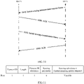
- FIG. 4 specifically shows a schematic structure of a spatial mapping matrix field according to an embodiment of this application.
- each spatial mapping matrix in the spatial mapping matrix field is separately indicated by using a column number field (namely, an Nc field), a row number field (namely, an Nr field), a quantization bit number field (namely, an FM field), a channel bandwidth field (namely, a bandwidth (bandwidth, BW) field), and a matrix field.
- Content specifically indicated in each field is shown in Table 2. It may be understood that, when the indication frame indicates a plurality of spatial mapping matrices, the spatial mapping matrix field includes a plurality of groups of Nc fields, Nr fields, BW fields, FM fields, and matrix fields.
- Quantization of the spatial mapping matrix means that the spatial mapping matrix finally needs to be converted into a bit stream of 0 and 1.
- Each element in the spatial mapping matrix needs to be indicated by using a binary number with a specific length, a process of converting the element into the binary number is quantization, and a length of the binary number obtained through conversion is the number of quantization bits in Table 2.
- the spatial mapping matrix is usually a unitary matrix, the unitary matrix may be converted into a plurality of angle parameters with reference to a Given Rotation method in compressed beamforming feedback in the 802.11 standard, and then the angle parameters are quantized, so that a length of information used for indicating the spatial mapping matrix can be compressed.
- each type of spatial mapping matrix may alternatively be numbered, so that only a number or an index of a corresponding spatial mapping matrix needs to be stored in the spatial mapping matrix field. In this way, the length of the information used for indicating the spatial mapping matrix can be further reduced.
- the first device may learn of spatial mapping matrices to be used by the second device in different channel bandwidths and/or different numbers of space time streams.
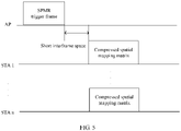
- the second device sends a response frame for a trigger (trigger) frame to the first device, in other words, the indication frame is the response frame.
- step 250 may be further performed.
- the first device sends the trigger frame to the second device, where the trigger frame is used for requesting the second device to feed back spatial mapping matrices to be used by the second device in different channel bandwidths and/or different numbers of space time streams.
- the trigger frame corresponds to the request frame in FIG. 2 .
- the first device sends a spatial mapping matrix request (spatial mapping matrix request, SPMR) trigger frame to the second device, to trigger the second device to feed back spatial mapping matrices to be used by the second device in different channel bandwidths and/or different numbers of space time streams.
- SPMR spatial mapping matrix request
- the second device After receiving the SPMR trigger frame, the second device sends the indication frame to the first device in response to the SPMR trigger frame, where the indication frame is used for indicating the spatial mapping matrices to be used by the second device in different channel bandwidths and/or different numbers of space time streams.
- the second device may alternatively add only the spatial mapping matrix field to the indication frame and does not need to add a new element.
- FIG. 6 shows a format of an SPMR trigger frame according to an embodiment of this application.
- FIG. 7 shows a format of a common information field according to an embodiment of this application.
- a new trigger type is added to trigger types of the common information field of the SPMR trigger frame, to indicate the second device receiving the SPMR trigger frame to feed back the spatial mapping matrices to be used by the second device.
- Table 3 lists some trigger types that may be carried in the common information field. When a value of a trigger type field is 9, a corresponding spatial mapping matrix report is a newly added trigger type. Table 3 Value of a trigger type field Trigger frame type 0 Basic trigger frame 1 Beamforming report poll trigger frame 2 Multi-user block acknowledgement request trigger frame 3 Multi-user request to send trigger frame 4 Buffer status report poll trigger frame 5 Groupcast with retries multi-user block acknowledgement request trigger frame 6 Bandwidth query report poll trigger frame 7 Null data packet feedback report poll trigger frame 8 Ranging trigger frame 9 Spatial mapping matrix report trigger frame 10 to 15 Reserved
- the first device may send the SPMR trigger frame to a plurality of second devices.
- the first device broadcasts the SPMR trigger frame.
- the plurality of second devices receiving the SPMR trigger frame each feed back an indication frame to the first device.
- the first device determines, based on the received indication frame, real channel state information between the first device and the second device sending the indication frame.
- the first device performs sensing, positioning, and the like on an ambient environment or a passive target by integrating a plurality of pieces of actual channel state information.
- the second device sends a null data packet announcement (null data packet announcement, NDPA) frame to the first device, in other words, the indication frame is the NDPA frame.
- NDPA null data packet announcement
- the second device may send the NDPA frame to the first station, to indicate the spatial mapping matrix to be subsequently used by the second device to send an NDP frame.
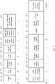
- FIG. 9 shows a frame structure of an NDPA frame according to an embodiment of this application.
- the spatial mapping matrix field is a newly added field. For a specific format of the spatial mapping matrix field, refer to the related description of FIG. 4 , and details are not described herein again.
- a negotiation phase may exist.
- the first device and the second device exchange parameters and capabilities of sensing measurement.
- the first device sends an initial sensing measurement request frame to the second device, and correspondingly, the second device receives the initial sensing measurement request frame sent by the first device, where the initial sensing measurement request frame is used for requesting the second device to assist in sensing measurement.
- the second device after receiving the initial sensing measurement request frame, the second device first replies with an acknowledgement (acknowledgement, ACK) frame, to feed back to the first device that the initial sensing measurement request frame is already correctly received.
- acknowledgement acknowledgement
- the second device determines, based on a condition of the second device, whether to respond to the request of the first device. If the second device agrees to the request for performing sensing measurement, the second device sends an initial sensing measurement frame to the first device, or the second device sends the initial sensing measurement frame to the first device after a period of time, where the period of time cannot be greater than a preset threshold. If the second device does not agree to perform sensing measurement, the second device does not send the initial sensing measurement frame to the first device, and the first device considers that the second device does not agree to perform sensing measurement when the period of time exceeds the preset threshold.
- the first device replies to the second device with an ACK frame, and the negotiation process ends at this time.
- the second device may indicate, in the initial sensing measurement frame, the spatial mapping matrix used by the second device, in other words, the indication frame is the initial sensing measurement frame.
- the foregoing initial sensing measurement request frame may correspond to the request frame in FIG. 2 .
- the first device may also indicate, in the initial sensing measurement request frame, the spatial mapping matrix used by the first device.
- the initial sensing measurement request frame and the initial sensing measurement frame may use a same frame structure to simplify a design process.
- the initial sensing measurement request frame and the initial sensing measurement frame each may carry a sensing parameter element
- the spatial mapping matrix element shown in FIG 3 and FIG 4 may be further added to a sub-element of the sensing parameter element, or the spatial mapping matrix field shown in FIG 4 may be added to the sensing parameter element.
- the spatial mapping matrix element shown in FIG 3 and FIG. 4 is added to the sub-element of the sensing parameter element.
- a structure of the sensing parameter element may be shown in FIG. 11 .
- the indication frame in this embodiment of this application may alternatively be a dedicated illuminating frame for sensing measurement, and the illuminating frame may include a segment of radar signals such as FMCE.
- the second device may indicate the foregoing one or more spatial mapping matrices to the first device by using the illuminating frame.
- the illuminating frame may carry the spatial mapping matrix element shown in FIG. 3 and FIG. 4 , or carry the spatial mapping matrix field shown in FIG. 4 . This is not specifically limited in this embodiment of this application.
- the indication frame in this embodiment of this application may be in any form, provided that the second device can indicate, to the first device, the one or more spatial mapping matrices that may be used by the second device.
- the first device determines channel state information based on the spatial mapping matrix and a channel estimation result, and performs sensing measurement based on the actual channel state information.
- the first device needs to obtain the channel estimation result.
- 240 may be performed.
- the first device determines, based on information about a channel bandwidth and/or a number of space time streams carried in the measurement frame, Q in the plurality of spatial mapping matrices obtained by using the indication frame, and further, the first device obtains, based on the channel estimation result C and the spatial mapping matrix Q, the channel state information H from which impact of spatial mapping is eliminated.
- H C x Q H , where Q H is a conjugate transpose of Q.
- the first device can obtain the actual channel state information, or in other words, the channel state information from which the impact of spatial mapping is eliminated, to complete sensing, positioning, and the like on the ambient environment or the passive target by using the obtained actual channel state information.
- the measurement frame may be a null data packet (null data packet, NDP) frame.
- NDP null data packet
- the dedicated illuminating frame when the indication frame is a dedicated illuminating frame, the dedicated illuminating frame may alternatively be used as a measurement frame. In other words, when indicating the spatial mapping matrix used by the second device, the dedicated illuminating frame may also be used as a measurement signal.
- the first device may further feed back a sensing measurement result to the second device, in other words, perform 260.
- each device in a communication network not only can perform sensing measurement by itself, but also can obtain a sensing measurement result of another device, and can obtain a more accurate measurement result by analyzing more information.
- the apparatus for sensing measurement includes corresponding hardware structures and/or software modules for performing the functions.
- a person skilled in the art should easily be aware that, in combination with the units and the method steps in the examples described in the embodiments disclosed in this application, this application can be implemented by hardware or a combination of hardware and computer software. Whether a function is performed by hardware or hardware driven by computer software depends on particular application scenarios and design constraints of the technical solutions.
- the following describes apparatus embodiments of this application with reference to FIG 14 to FIG. 17 . These apparatuses may be configured to implement the functions of the first device or the second device in the foregoing method embodiment, and therefore can also achieve the beneficial effects of the foregoing method embodiment.
- FIG. 14 is a schematic diagram of a structure of an apparatus for sensing measurement according to an embodiment of this application.
- An apparatus 1400 shown in FIG. 14 may be the first device shown in FIG. 1 , or a module (for example, a chip) used in the first device.
- the apparatus 1400 includes a receiving unit 1410 and a processing unit 1430.
- the receiving unit 1410 is configured to receive an indication frame, where the indication frame is used for indicating a spatial mapping matrix.
- the processing unit 1430 is configured to determine channel state information based on the spatial mapping matrix and a channel estimation result.
- the indication frame includes a spatial mapping matrix field, and the spatial mapping matrix field is used for indicating the spatial mapping matrix.
- the spatial mapping matrix field includes at least one of a column number field, a row number field, a quantization bit number field, and a channel bandwidth field, where the column number field is used for indicating a number of columns of the spatial mapping matrix, the row number field is used for indicating a number of rows of the spatial mapping matrix, the quantization bit number field is used for indicating a number of quantization bits of the spatial mapping matrix, and the channel bandwidth field is used for indicating a channel bandwidth.
- the spatial mapping matrix field further includes a matrix field, and the matrix field is used for indicating bit sequences of the spatial mapping matrix after quantization.
- the spatial mapping matrix field includes an index of the spatial mapping matrix.
- the indication frame includes a spatial mapping matrix element
- the spatial mapping matrix element includes the spatial mapping matrix field and at least one of an element ID field used for indicating an element identity (ID), an element length field used for indicating a length of the spatial mapping matrix field, and an element ID extension field used for indicating element ID extension.
- the apparatus 1400 further includes a sending unit 1420, configured to send a request frame before the indication frame is received, where the request frame is used for requesting to feed back the spatial mapping matrix.
- a sending unit 1420 configured to send a request frame before the indication frame is received, where the request frame is used for requesting to feed back the spatial mapping matrix.
- the request frame is a trigger frame
- the trigger frame includes a first trigger type
- the first trigger type is used for triggering to feed back the spatial mapping matrix.
- the indication frame includes at least one of a beacon frame, a null data packet announcement (NDPA) frame, a response frame for the trigger frame, and a dedicated illuminating frame, and the dedicated illuminating frame is further used for obtaining the channel estimation result.
- NDPA null data packet announcement
- the receiving module 1410 and the sending module 1420 may be implemented by a transceiver.
- the processing module 1430 may be implemented by a processor. For specific functions and beneficial effects of the receiving module 1410, the sending module 1420, and the processing module 1430, refer to the foregoing method embodiment. Details are not described herein again.
- FIG. 15 is a schematic diagram of a structure of an apparatus for sensing measurement according to another embodiment of this application.
- An apparatus 1500 shown in FIG 15 may be the second device shown in FIG. 1 , or a module (for example, a chip) used in the second device.
- the apparatus 1500 includes a sending unit 1520 and a processing unit 1530.
- the processing unit 1530 is configured to generate an indication frame, where the indication frame is used for indicating a spatial mapping matrix.
- the sending unit 1520 is configured to send the indication frame.
- the indication frame includes a spatial mapping matrix field, and the spatial mapping matrix field is used for indicating the spatial mapping matrix.
- the spatial mapping matrix field includes at least one of a column number field, a row number field, a quantization bit number field, and a channel bandwidth field, where the column number field is used for indicating a number of columns of the spatial mapping matrix, the row number field is used for indicating a number of rows of the spatial mapping matrix, the quantization bit number field is used for indicating a number of quantization bits of the spatial mapping matrix, and the channel bandwidth field is used for indicating a channel bandwidth.
- the spatial mapping matrix field further includes a matrix field, and the matrix field is used for indicating bit sequences of the spatial mapping matrix after quantization.
- the spatial mapping matrix field includes an index of the spatial mapping matrix.
- the indication frame includes a spatial mapping matrix element
- the spatial mapping matrix element includes the spatial mapping matrix field and at least one of an element ID field used for indicating an element identity (ID), an element length field used for indicating a length of the spatial mapping matrix field, and an element ID extension field used for indicating element ID extension.
- the apparatus 1500 further includes a receiving unit 1510, configured to receive a request frame before the indication frame is sent, where the request frame is used for requesting to feed back the spatial mapping matrix.
- a receiving unit 1510 configured to receive a request frame before the indication frame is sent, where the request frame is used for requesting to feed back the spatial mapping matrix.
- the request frame is a trigger frame
- the trigger frame includes a first trigger type
- the first trigger type is used for triggering to feed back the spatial mapping matrix.
- the indication frame includes at least one of a beacon frame, a null data packet announcement (NDPA) frame, a response frame for the trigger frame, and a dedicated illuminating frame, and the dedicated illuminating frame is further used for obtaining a channel estimation result.
- NDPA null data packet announcement
- the receiving module 1510 and the sending module 1520 may be implemented by a transceiver.
- the processing module 1530 may be implemented by a processor. For specific functions and beneficial effects of the receiving module 1510, the sending module 1520, and the processing module 1530, refer to the foregoing method embodiment. Details are not described herein again.
- FIG. 16 is a schematic diagram of a structure of an apparatus for sensing measurement according to another embodiment of this application.
- An apparatus 1600 shown in FIG 16 may be the first device shown in FIG. 1 , or a module (for example, a chip) used in the first device.
- the apparatus 1600 may include a transceiver 1610, a processor 1620, and a memory 1630.
- FIG. 16 shows only one memory and one processor. In an actual product, there may be one or more processors and one or more memories.
- the memory may also be referred to as a storage medium, a storage device, or the like.
- the memory may be disposed independent of the processor, or may be integrated with the processor. This is not limited in this embodiment of this application.
- the transceiver 1610, the processor 1620, and the memory 1630 communicate with each other through an internal connection path and transfer a control signal and/or a data signal.
- the transceiver 1610 is configured to receive an indication frame, where the indication frame is used for indicating a spatial mapping matrix.
- the processor 1620 is configured to determine channel state information based on the spatial mapping matrix and a channel estimation result.
- FIG. 17 is a schematic diagram of a structure of an apparatus for sensing measurement according to another embodiment of this application.
- An apparatus 1700 shown in FIG 17 may be the second device shown in FIG. 1 , or a module (for example, a chip) used in the second device.
- the apparatus 1700 may include a transceiver 1710, a processor 1720, and a memory 1730.
- FIG. 17 shows only one memory and one processor.
- the memory may also be referred to as a storage medium, a storage device, or the like.
- the memory may be disposed independent of the processor, or may be integrated with the processor. This is not limited in this embodiment of this application.
- the transceiver 1710, the processor 1720, and the memory 1730 communicate with each other through an internal connection path and transfer a control signal and/or a data signal.
- the processor 1720 is configured to generate an indication frame, where the indication frame is used for indicating a spatial mapping matrix.
- the transceiver 1710 is configured to send the indication frame.
- the transceiver in the embodiments of this application may also be referred to as a transceiver unit, a transceiver machine, a transceiver apparatus, or the like.
- the processor may also be referred to as a processing unit, a processing board, a processing module, a processing apparatus, or the like.
- a component that is in the transceiver and that is configured to implement a receiving function may be considered as a receiving unit
- a component that is in the transceiver and that is configured to implement a sending function may be considered as a sending unit.
- the transceiver includes the receiving unit and the sending unit.
- the receiving unit may also be sometimes referred to as a receiver machine, a receiver, a receiver circuit, or the like.
- the sending unit may also be sometimes referred to as a transmitter machine, a transmitter, a transmitter circuit, or the like.
- the memory described in the embodiments of this application is configured to store computer instructions and a parameter for running the processor.
- the processor in the embodiments of this application may be an integrated circuit chip, and has a signal processing capability. In an implementation process, the steps in the foregoing methods may be completed by using a hardware integrated logical circuit in the processor, or by using instructions in a form of software.
- the processor in the embodiments of this application may be a general-purpose processor, a digital signal processor (digital signal processor, DSP), an application-specific integrated circuit (application-specific integrated circuit, ASIC), a field programmable gate array (field programmable gate array, FPGA) or another programmable logic device, a discrete gate or transistor logic device, or a discrete hardware component.
- DSP digital signal processor
- ASIC application-specific integrated circuit
- FPGA field programmable gate array
- the methods, the steps, and the logic block diagrams that are disclosed in the embodiments of this application may be implemented or performed.
- the general-purpose processor may be a microprocessor, or the processor may be any conventional processor or the like.
- the steps of the methods disclosed with reference to the embodiments of this application may be directly presented as being performed and completed by a hardware decoding processor, or performed and completed by a combination of hardware and a software module in a decoding processor.
- the software module may be located in a mature storage medium in the art, for example, a random access memory (random access memory, RAM), a flash memory, a read-only memory (read-only memory, ROM), a programmable read-only memory, an electrically erasable programmable memory, or a register.
- the storage medium is located in the memory, and the processor reads instructions in the memory and completes the steps in the foregoing methods in combination with hardware of the processor.
- Sequence numbers of the processes do not mean execution sequences in various embodiments of this application.
- the execution sequences of the processes should be determined based on functions and internal logic of the processes, and should not be construed as any limitation on the implementation processes of the embodiments of this application.
- a specific structure of an execution body of the method provided in the embodiments of this application is not specially limited in the embodiments of this application, provided that a program that records code of the method provided in the embodiments of this application can be run to perform communication according to the method provided in the embodiments of this application.
- the method provided in the embodiments of this application may be performed by the AP or the STA, or a functional module that can invoke and execute the program in the AP or the STA.
- aspects or features of this application may be implemented as a method, an apparatus, or a product that uses standard programming and/or engineering technologies.
- product used in this application covers a computer program that can be accessed from any computer-readable component, carrier, or medium.
- the computer-readable medium may include but is not limited to: a magnetic storage component (for example, a hard disk, a floppy disk, or a magnetic tape), an optical disc (for example, a compact disc (compact disc, CD) or a digital versatile disc (digital versatile disc, DVD)), a smart card, and a flash memory component (for example, an erasable programmable read-only memory (erasable programmable read-only memory, EPROM), a card, a stick, or a key drive).
- various storage media described in this specification may represent one or more devices and/or other machine-readable media that are configured to store information.
- the term "machine-readable media" may include but is not limited to a radio channel and various other media that can store, include, and/or carry instructions and/or data.
- system and “network” in this specification may usually be used interchangeably.
- the term “and/or” in this application describes only an association relationship for describing associated objects and indicates that three relationships may exist. For example, A and/or B may indicate the following three cases: Only A exists, both A and B exist, and only B exists.
- the character “/" in this specification generally indicates an "or" relationship between the associated objects.
- All or some of the foregoing embodiments may be implemented by using software, hardware, firmware, or any combination thereof.
- the embodiments may be implemented entirely or partially in a form of a computer program product.
- the computer program product includes one or more computer instructions.
- the computer program instructions When the computer program instructions are loaded and executed on a computer, the procedures or functions according to the embodiments of this application are all or partially generated.
- the computer may be a general-purpose computer, a special-purpose computer, a computer network, or another programmable apparatus.
- the computer instructions may be stored in a computer-readable storage medium or may be transmitted from a computer-readable storage medium to another computer-readable storage medium.
- the computer instructions may be transmitted from a website, computer, server, or data center to another website, computer, server, or data center in a wired (for example, a coaxial cable, an optical fiber, or a digital subscriber line (digital subscriber line, DSL)) or wireless (for example, infrared, radio, or microwave) manner.
- the computer-readable storage medium may be any usable medium accessible by a computer, or a data storage device, for example, a server or a data center, integrating one or more usable media.
- the usable medium may be a magnetic medium (for example, a floppy disk, a hard disk, or a magnetic tape), an optical medium (for example, a digital video disc (digital video disc, DVD)), a semiconductor medium (for example, a solid-state drive (solid state disk, SSD)), or the like.
- a magnetic medium for example, a floppy disk, a hard disk, or a magnetic tape
- an optical medium for example, a digital video disc (digital video disc, DVD)
- a semiconductor medium for example, a solid-state drive (solid state disk, SSD)
- the disclosed system, apparatus, and method may be implemented in other manners.
- the described apparatus embodiment is merely an example.
- division into units is merely logical function division and may be other division in actual implementation.
- a plurality of units or components may be combined or integrated into another system, or some features may be ignored or not performed.
- the displayed or discussed mutual couplings or direct couplings or communication connections may be implemented through some interfaces.
- the indirect couplings or communication connections between the apparatuses or units may be implemented in electronic, mechanical, or other forms.
- the units described as separate parts may or may not be physically separate, and parts displayed as units may or may not be physical units, may be located in one location, or may be distributed on a plurality of network units. Some or all of the units may be selected based on actual requirements to achieve the objectives of the solutions of the embodiments.
- the functions When the functions are implemented in a form of a software functional unit and sold or used as an independent product, the functions may be stored in a computer-readable storage medium. Based on such an understanding, the technical solutions of this application essentially, or the part contributing to the conventional technology, or some of the technical solutions may be implemented in a form of a software product.
- the computer software product is stored in a storage medium, and includes several instructions for instructing a computer device (which may be a personal computer, a server, or a network device) to perform all or some of the steps of the methods described in the embodiments of this application.
- the storage medium includes any medium that can store program code, for example, a USB flash drive, a removable hard disk, a read-only memory (read-only memory, ROM), a random access memory (random access memory, RAM), a magnetic disk, or an optical disc.
- program code for example, a USB flash drive, a removable hard disk, a read-only memory (read-only memory, ROM), a random access memory (random access memory, RAM), a magnetic disk, or an optical disc.
Landscapes
- Engineering & Computer Science (AREA)
- Signal Processing (AREA)
- Computer Networks & Wireless Communication (AREA)
- Power Engineering (AREA)
- Quality & Reliability (AREA)
- Physics & Mathematics (AREA)
- Electromagnetism (AREA)
- Mobile Radio Communication Systems (AREA)
Applications Claiming Priority (2)
| Application Number | Priority Date | Filing Date | Title |
|---|---|---|---|
| CN201910865373.8A CN112491750B (zh) | 2019-09-12 | 2019-09-12 | 用于感知测量的方法和装置 |
| PCT/CN2020/114790 WO2021047640A1 (fr) | 2019-09-12 | 2020-09-11 | Procédé et appareil de détection et de mesure |
Publications (3)
| Publication Number | Publication Date |
|---|---|
| EP4024794A1 true EP4024794A1 (fr) | 2022-07-06 |
| EP4024794A4 EP4024794A4 (fr) | 2022-10-05 |
| EP4024794B1 EP4024794B1 (fr) | 2025-01-01 |
Family
ID=74866571
Family Applications (1)
| Application Number | Title | Priority Date | Filing Date |
|---|---|---|---|
| EP20864208.2A Active EP4024794B1 (fr) | 2019-09-12 | 2020-09-11 | Procédé et appareil de détection et de mesure |
Country Status (4)
| Country | Link |
|---|---|
| US (1) | US11831574B2 (fr) |
| EP (1) | EP4024794B1 (fr) |
| CN (1) | CN112491750B (fr) |
| WO (1) | WO2021047640A1 (fr) |
Cited By (1)
| Publication number | Priority date | Publication date | Assignee | Title |
|---|---|---|---|---|
| EP4408088A4 (fr) * | 2021-09-22 | 2025-01-22 | Vivo Mobile Communication Co., Ltd. | Procédé et appareil de détection de communication, et dispositif de communication |
Families Citing this family (21)
| Publication number | Priority date | Publication date | Assignee | Title |
|---|---|---|---|---|
| CN115118318A (zh) * | 2021-03-22 | 2022-09-27 | 华为技术有限公司 | 基于信道状态信息反馈的方法、设备和介质 |
| CN113132917B (zh) * | 2021-04-15 | 2022-04-01 | 成都极米科技股份有限公司 | 感知进程中发送和接收感知信号的方法、装置及存储介质 |
| CN115348622A (zh) * | 2021-05-12 | 2022-11-15 | 维沃移动通信有限公司 | 信息处理方法、装置、终端和网络侧设备 |
| CA3173366A1 (fr) | 2021-05-26 | 2023-11-25 | Christopher Beg | Systemes et procedes d'adaptation de flexibilite dans des transmissions de detection |
| CN115413018A (zh) * | 2021-05-26 | 2022-11-29 | 中兴通讯股份有限公司 | 信道状态信息处理方法、终端和计算机可读存储介质 |
| WO2023272455A1 (fr) * | 2021-06-28 | 2023-01-05 | Oppo广东移动通信有限公司 | Procédé et dispositif de communication sans fil |
| CN115734198A (zh) * | 2021-09-01 | 2023-03-03 | 华为技术有限公司 | 通信方法及装置 |
| CN115765941B (zh) * | 2021-09-03 | 2025-04-18 | 展讯通信(上海)有限公司 | 通信方法及装置、计算机可读存储介质、通信设备 |
| EP4398661A4 (fr) * | 2021-09-03 | 2024-11-06 | Beijing Xiaomi Mobile Software Co., Ltd. | Procédé et appareil de configuration de signal de détection, équipement utilisateur, dispositif côté réseau et support de stockage |
| US20250240653A1 (en) * | 2021-10-22 | 2025-07-24 | Beijing Xiaomi Mobile Software Co., Ltd. | Communication method and communication apparatus |
| WO2023065308A1 (fr) * | 2021-10-22 | 2023-04-27 | 北京小米移动软件有限公司 | Procédé de communication et appareil de communication pour mesure de détection de réseau local sans fil |
| WO2023097585A1 (fr) * | 2021-12-01 | 2023-06-08 | 北京小米移动软件有限公司 | Procédé et appareil de fin de mesure de détection de réseau local sans fil, et dispositif et support de stockage |
| CN118476194A (zh) * | 2022-01-07 | 2024-08-09 | Oppo广东移动通信有限公司 | 感知方法、感知代理请求设备和感知代理响应设备 |
| CN116546541B (zh) * | 2022-01-25 | 2026-04-28 | 极米科技股份有限公司 | 伺机感知测量方法、装置、设备及存储介质 |
| CN116866819A (zh) * | 2022-03-28 | 2023-10-10 | 华为技术有限公司 | 测量方法及测量装置 |
| CN117242814A (zh) * | 2022-04-14 | 2023-12-15 | 北京小米移动软件有限公司 | 通信方法、装置、设备以及存储介质 |
| WO2023212924A1 (fr) * | 2022-05-06 | 2023-11-09 | 北京小米移动软件有限公司 | Procédé de communication pour la détection d'un établissement de session, et appareil de communication |
| US20230134385A1 (en) * | 2022-06-09 | 2023-05-04 | Intel Corporation | Apparatus, system, and method of a transmission configured for channel-sounding-based measurement |
| CN115103382B (zh) * | 2022-06-27 | 2024-05-28 | 西南交通大学 | 一种多目标无线感知方法和系统 |
| WO2024016292A1 (fr) * | 2022-07-21 | 2024-01-25 | 北京小米移动软件有限公司 | Procédé et appareil de communication, dispositif et support de stockage |
| CN116918309A (zh) * | 2023-05-18 | 2023-10-20 | 北京小米移动软件有限公司 | 感知方法、装置、设备及存储介质 |
Family Cites Families (11)
| Publication number | Priority date | Publication date | Assignee | Title |
|---|---|---|---|---|
| US8085873B2 (en) * | 2007-01-02 | 2011-12-27 | Qualcomm, Incorporated | Systems and methods for enhanced channel estimation in wireless communication systems |
| US8903019B2 (en) * | 2008-10-29 | 2014-12-02 | Cisco Technology, Inc. | Multidimensional channel estimation without sounding signals |
| EP2491663B1 (fr) * | 2009-10-23 | 2015-07-29 | Marvell World Trade Ltd. | Indication de séquence d'apprentissage pour réseau WLAN |
| CN101764678B (zh) * | 2009-12-16 | 2012-11-07 | 北京邮电大学 | 基于空间映射的中继方法和装置 |
| US9337954B2 (en) * | 2010-07-28 | 2016-05-10 | Qualcomm Incorporated | Protocol for channel state information feedback |
| CN103378893A (zh) * | 2012-04-28 | 2013-10-30 | 中兴通讯股份有限公司 | 开环数据发送的方法及装置 |
| US9693385B2 (en) * | 2013-03-24 | 2017-06-27 | Avago Technologies General Ip (Singapore) Pte. Ltd | Shared PLCP protocol data unit (PPDU) within wireless communications |
| US10886988B2 (en) * | 2017-06-19 | 2021-01-05 | Intel IP Corporation | Apparatus, system and method of communicating a physical layer protocol data unit (PPDU) |
| WO2020061183A1 (fr) * | 2018-09-18 | 2020-03-26 | Sethi, Ankit | Transmission de symboles de champ d'apprentissage à long terme à efficacité élevée pour de multiples flux de transmission |
| JP2022554138A (ja) * | 2019-10-31 | 2022-12-28 | ソニーグループ株式会社 | 通信デバイスおよび方法 |
| US20210288779A1 (en) * | 2020-06-03 | 2021-09-16 | Claudio Da Silva | Wireless local area network sensing sounding |
-
2019
- 2019-09-12 CN CN201910865373.8A patent/CN112491750B/zh active Active
-
2020
- 2020-09-11 EP EP20864208.2A patent/EP4024794B1/fr active Active
- 2020-09-11 WO PCT/CN2020/114790 patent/WO2021047640A1/fr not_active Ceased
-
2022
- 2022-03-11 US US17/692,292 patent/US11831574B2/en active Active
Cited By (1)
| Publication number | Priority date | Publication date | Assignee | Title |
|---|---|---|---|---|
| EP4408088A4 (fr) * | 2021-09-22 | 2025-01-22 | Vivo Mobile Communication Co., Ltd. | Procédé et appareil de détection de communication, et dispositif de communication |
Also Published As
| Publication number | Publication date |
|---|---|
| US11831574B2 (en) | 2023-11-28 |
| CN112491750B (zh) | 2024-09-24 |
| US20220200753A1 (en) | 2022-06-23 |
| WO2021047640A1 (fr) | 2021-03-18 |
| EP4024794B1 (fr) | 2025-01-01 |
| CN112491750A (zh) | 2021-03-12 |
| EP4024794A4 (fr) | 2022-10-05 |
Similar Documents
| Publication | Publication Date | Title |
|---|---|---|
| US11831574B2 (en) | Method and apparatus for sensing measurement | |
| KR102528328B1 (ko) | 채널 상태 정보 피드백 방법 및 장치 | |
| EP4192074A1 (fr) | Procédé et appareil de détection | |
| US12231190B2 (en) | Apparatus and method for wireless communication based on enhanced null data packet announcement | |
| EP2599239B1 (fr) | Techniques de prise en charge mac mimo à utilisateurs multiples en liaison montante | |
| US20180235004A1 (en) | Method of multiple frame transmission in wireless communication system and transmitter | |
| CN113037400A (zh) | 信道探测方法及装置 | |
| CN113114430A (zh) | 一种数据帧的接收状态确定方法及通信装置 | |
| HUE032245T2 (en) | A method and apparatus for transmitting a spatial data stream for MU-MIMO in a wireless local area network system | |
| MX2008009166A (es) | Metodo y aparato para distribuir informacion de baliza. | |
| EP4178294A1 (fr) | Procédé et appareil d'apprentissage de faisceau | |
| JP2025541175A (ja) | サウンディングにおける追加ltfのための通信装置および通信方法 | |
| KR20240093617A (ko) | 안테나 채널 탐측 방법, 장치 및 저장 매체 | |
| CN116437383A (zh) | 多链路通信的探测请求方法及装置 | |
| US20190199492A1 (en) | A method, a base station and a mobile station for transmitting and detecting reference signals | |
| CN117015941A (zh) | 一种天线切换能力上报方法及其装置 | |
| EP4482049A1 (fr) | Procédé de détermination d'une matrice de précodage de liaison montante, et appareil de communication | |
| EP4489466A1 (fr) | Procédé et appareil de transmission d'informations | |
| US20260031864A1 (en) | Method for determining precoding matrix for uplink mimo transmission, and apparatus for same | |
| EP4572458A1 (fr) | Procédé et appareil d'indication de précodage prenant en charge une transmission de canal pusch basée sur un registre de codes 8tx | |
| CN121569452A (zh) | 一种通信方法及通信装置 | |
| CN120153685A (zh) | 一种上行波束指示方法及其装置 | |
| CN118104193A (zh) | 一种确定频偏的方法和装置 | |
| WO2022042287A1 (fr) | Procédé de traitement d'informations d'état de canal et appareil de communication | |
| CN116156629A (zh) | 波束恢复方法、波束失败检测方法以及相关装置 |
Legal Events
| Date | Code | Title | Description |
|---|---|---|---|
| STAA | Information on the status of an ep patent application or granted ep patent |
Free format text: STATUS: THE INTERNATIONAL PUBLICATION HAS BEEN MADE |
|
| PUAI | Public reference made under article 153(3) epc to a published international application that has entered the european phase |
Free format text: ORIGINAL CODE: 0009012 |
|
| STAA | Information on the status of an ep patent application or granted ep patent |
Free format text: STATUS: REQUEST FOR EXAMINATION WAS MADE |
|
| 17P | Request for examination filed |
Effective date: 20220331 |
|
| AK | Designated contracting states |
Kind code of ref document: A1 Designated state(s): AL AT BE BG CH CY CZ DE DK EE ES FI FR GB GR HR HU IE IS IT LI LT LU LV MC MK MT NL NO PL PT RO RS SE SI SK SM TR |
|
| A4 | Supplementary search report drawn up and despatched |
Effective date: 20220907 |
|
| RIC1 | Information provided on ipc code assigned before grant |
Ipc: H04L 25/02 20060101AFI20220901BHEP |
|
| DAV | Request for validation of the european patent (deleted) | ||
| DAX | Request for extension of the european patent (deleted) | ||
| GRAP | Despatch of communication of intention to grant a patent |
Free format text: ORIGINAL CODE: EPIDOSNIGR1 |
|
| STAA | Information on the status of an ep patent application or granted ep patent |
Free format text: STATUS: GRANT OF PATENT IS INTENDED |
|
| INTG | Intention to grant announced |
Effective date: 20240830 |
|
| GRAS | Grant fee paid |
Free format text: ORIGINAL CODE: EPIDOSNIGR3 |
|
| GRAA | (expected) grant |
Free format text: ORIGINAL CODE: 0009210 |
|
| STAA | Information on the status of an ep patent application or granted ep patent |
Free format text: STATUS: THE PATENT HAS BEEN GRANTED |
|
| AK | Designated contracting states |
Kind code of ref document: B1 Designated state(s): AL AT BE BG CH CY CZ DE DK EE ES FI FR GB GR HR HU IE IS IT LI LT LU LV MC MK MT NL NO PL PT RO RS SE SI SK SM TR |
|
| REG | Reference to a national code |
Ref country code: GB Ref legal event code: FG4D |
|
| P01 | Opt-out of the competence of the unified patent court (upc) registered |
Free format text: CASE NUMBER: APP_63516/2024 Effective date: 20241129 |
|
| REG | Reference to a national code |
Ref country code: DE Ref legal event code: R096 Ref document number: 602020044264 Country of ref document: DE |
|
| REG | Reference to a national code |
Ref country code: CH Ref legal event code: EP |
|
| REG | Reference to a national code |
Ref country code: IE Ref legal event code: FG4D |
|
| REG | Reference to a national code |
Ref country code: LT Ref legal event code: MG9D |
|
| REG | Reference to a national code |
Ref country code: NL Ref legal event code: MP Effective date: 20250101 |
|
| REG | Reference to a national code |
Ref country code: AT Ref legal event code: MK05 Ref document number: 1757438 Country of ref document: AT Kind code of ref document: T Effective date: 20250101 |
|
| PG25 | Lapsed in a contracting state [announced via postgrant information from national office to epo] |
Ref country code: NL Free format text: LAPSE BECAUSE OF FAILURE TO SUBMIT A TRANSLATION OF THE DESCRIPTION OR TO PAY THE FEE WITHIN THE PRESCRIBED TIME-LIMIT Effective date: 20250101 |
|
| PG25 | Lapsed in a contracting state [announced via postgrant information from national office to epo] |
Ref country code: FI Free format text: LAPSE BECAUSE OF FAILURE TO SUBMIT A TRANSLATION OF THE DESCRIPTION OR TO PAY THE FEE WITHIN THE PRESCRIBED TIME-LIMIT Effective date: 20250101 |
|
| PG25 | Lapsed in a contracting state [announced via postgrant information from national office to epo] |
Ref country code: PL Free format text: LAPSE BECAUSE OF FAILURE TO SUBMIT A TRANSLATION OF THE DESCRIPTION OR TO PAY THE FEE WITHIN THE PRESCRIBED TIME-LIMIT Effective date: 20250101 |
|
| PG25 | Lapsed in a contracting state [announced via postgrant information from national office to epo] |
Ref country code: ES Free format text: LAPSE BECAUSE OF FAILURE TO SUBMIT A TRANSLATION OF THE DESCRIPTION OR TO PAY THE FEE WITHIN THE PRESCRIBED TIME-LIMIT Effective date: 20250101 |
|
| PG25 | Lapsed in a contracting state [announced via postgrant information from national office to epo] |
Ref country code: IS Free format text: LAPSE BECAUSE OF FAILURE TO SUBMIT A TRANSLATION OF THE DESCRIPTION OR TO PAY THE FEE WITHIN THE PRESCRIBED TIME-LIMIT Effective date: 20250501 Ref country code: NO Free format text: LAPSE BECAUSE OF FAILURE TO SUBMIT A TRANSLATION OF THE DESCRIPTION OR TO PAY THE FEE WITHIN THE PRESCRIBED TIME-LIMIT Effective date: 20250401 |
|
| PG25 | Lapsed in a contracting state [announced via postgrant information from national office to epo] |
Ref country code: HR Free format text: LAPSE BECAUSE OF FAILURE TO SUBMIT A TRANSLATION OF THE DESCRIPTION OR TO PAY THE FEE WITHIN THE PRESCRIBED TIME-LIMIT Effective date: 20250101 |
|
| PG25 | Lapsed in a contracting state [announced via postgrant information from national office to epo] |
Ref country code: LV Free format text: LAPSE BECAUSE OF FAILURE TO SUBMIT A TRANSLATION OF THE DESCRIPTION OR TO PAY THE FEE WITHIN THE PRESCRIBED TIME-LIMIT Effective date: 20250101 Ref country code: PT Free format text: LAPSE BECAUSE OF FAILURE TO SUBMIT A TRANSLATION OF THE DESCRIPTION OR TO PAY THE FEE WITHIN THE PRESCRIBED TIME-LIMIT Effective date: 20250502 |
|
| PG25 | Lapsed in a contracting state [announced via postgrant information from national office to epo] |
Ref country code: GR Free format text: LAPSE BECAUSE OF FAILURE TO SUBMIT A TRANSLATION OF THE DESCRIPTION OR TO PAY THE FEE WITHIN THE PRESCRIBED TIME-LIMIT Effective date: 20250402 Ref country code: BG Free format text: LAPSE BECAUSE OF FAILURE TO SUBMIT A TRANSLATION OF THE DESCRIPTION OR TO PAY THE FEE WITHIN THE PRESCRIBED TIME-LIMIT Effective date: 20250101 |
|
| PG25 | Lapsed in a contracting state [announced via postgrant information from national office to epo] |
Ref country code: AT Free format text: LAPSE BECAUSE OF FAILURE TO SUBMIT A TRANSLATION OF THE DESCRIPTION OR TO PAY THE FEE WITHIN THE PRESCRIBED TIME-LIMIT Effective date: 20250101 |
|
| PG25 | Lapsed in a contracting state [announced via postgrant information from national office to epo] |
Ref country code: CZ Free format text: LAPSE BECAUSE OF FAILURE TO SUBMIT A TRANSLATION OF THE DESCRIPTION OR TO PAY THE FEE WITHIN THE PRESCRIBED TIME-LIMIT Effective date: 20250101 |
|
| PG25 | Lapsed in a contracting state [announced via postgrant information from national office to epo] |
Ref country code: SE Free format text: LAPSE BECAUSE OF FAILURE TO SUBMIT A TRANSLATION OF THE DESCRIPTION OR TO PAY THE FEE WITHIN THE PRESCRIBED TIME-LIMIT Effective date: 20250101 |
|
| REG | Reference to a national code |
Ref country code: DE Ref legal event code: R097 Ref document number: 602020044264 Country of ref document: DE |
|
| PG25 | Lapsed in a contracting state [announced via postgrant information from national office to epo] |
Ref country code: SM Free format text: LAPSE BECAUSE OF FAILURE TO SUBMIT A TRANSLATION OF THE DESCRIPTION OR TO PAY THE FEE WITHIN THE PRESCRIBED TIME-LIMIT Effective date: 20250101 |
|
| PG25 | Lapsed in a contracting state [announced via postgrant information from national office to epo] |
Ref country code: DK Free format text: LAPSE BECAUSE OF FAILURE TO SUBMIT A TRANSLATION OF THE DESCRIPTION OR TO PAY THE FEE WITHIN THE PRESCRIBED TIME-LIMIT Effective date: 20250101 |
|
| PGFP | Annual fee paid to national office [announced via postgrant information from national office to epo] |
Ref country code: DE Payment date: 20250730 Year of fee payment: 6 |
|
| PG25 | Lapsed in a contracting state [announced via postgrant information from national office to epo] |
Ref country code: IT Free format text: LAPSE BECAUSE OF FAILURE TO SUBMIT A TRANSLATION OF THE DESCRIPTION OR TO PAY THE FEE WITHIN THE PRESCRIBED TIME-LIMIT Effective date: 20250101 |
|
| PGFP | Annual fee paid to national office [announced via postgrant information from national office to epo] |
Ref country code: GB Payment date: 20250731 Year of fee payment: 6 |
|
| PGFP | Annual fee paid to national office [announced via postgrant information from national office to epo] |
Ref country code: FR Payment date: 20250808 Year of fee payment: 6 |
|
| PG25 | Lapsed in a contracting state [announced via postgrant information from national office to epo] |
Ref country code: EE Free format text: LAPSE BECAUSE OF FAILURE TO SUBMIT A TRANSLATION OF THE DESCRIPTION OR TO PAY THE FEE WITHIN THE PRESCRIBED TIME-LIMIT Effective date: 20250101 |
|
| PG25 | Lapsed in a contracting state [announced via postgrant information from national office to epo] |
Ref country code: RO Free format text: LAPSE BECAUSE OF FAILURE TO SUBMIT A TRANSLATION OF THE DESCRIPTION OR TO PAY THE FEE WITHIN THE PRESCRIBED TIME-LIMIT Effective date: 20250101 |
|
| PG25 | Lapsed in a contracting state [announced via postgrant information from national office to epo] |
Ref country code: SK Free format text: LAPSE BECAUSE OF FAILURE TO SUBMIT A TRANSLATION OF THE DESCRIPTION OR TO PAY THE FEE WITHIN THE PRESCRIBED TIME-LIMIT Effective date: 20250101 |
|
| PLBE | No opposition filed within time limit |
Free format text: ORIGINAL CODE: 0009261 |
|
| STAA | Information on the status of an ep patent application or granted ep patent |
Free format text: STATUS: NO OPPOSITION FILED WITHIN TIME LIMIT |
|
| 26N | No opposition filed |
Effective date: 20251002 |