EP4024993A1 - Procédé d'envoi d'un signal de référence, procédé, appareil et système de réception d'un signal de référence - Google Patents
Procédé d'envoi d'un signal de référence, procédé, appareil et système de réception d'un signal de référence Download PDFInfo
- Publication number
- EP4024993A1 EP4024993A1 EP19946009.8A EP19946009A EP4024993A1 EP 4024993 A1 EP4024993 A1 EP 4024993A1 EP 19946009 A EP19946009 A EP 19946009A EP 4024993 A1 EP4024993 A1 EP 4024993A1
- Authority
- EP
- European Patent Office
- Prior art keywords
- symbols
- time unit
- reference signal
- uplink
- time
- Prior art date
- Legal status (The legal status is an assumption and is not a legal conclusion. Google has not performed a legal analysis and makes no representation as to the accuracy of the status listed.)
- Granted
Links
Images








Classifications
-
- H—ELECTRICITY
- H04—ELECTRIC COMMUNICATION TECHNIQUE
- H04L—TRANSMISSION OF DIGITAL INFORMATION, e.g. TELEGRAPHIC COMMUNICATION
- H04L5/00—Arrangements affording multiple use of the transmission path
- H04L5/003—Arrangements for allocating sub-channels of the transmission path
- H04L5/0053—Allocation of signalling, i.e. of overhead other than pilot signals
-
- H—ELECTRICITY
- H04—ELECTRIC COMMUNICATION TECHNIQUE
- H04L—TRANSMISSION OF DIGITAL INFORMATION, e.g. TELEGRAPHIC COMMUNICATION
- H04L5/00—Arrangements affording multiple use of the transmission path
- H04L5/0001—Arrangements for dividing the transmission path
- H04L5/0003—Two-dimensional division
- H04L5/0005—Time-frequency
- H04L5/0007—Time-frequency the frequencies being orthogonal, e.g. OFDM(A) or DMT
- H04L5/0012—Hopping in multicarrier systems
-
- H—ELECTRICITY
- H04—ELECTRIC COMMUNICATION TECHNIQUE
- H04L—TRANSMISSION OF DIGITAL INFORMATION, e.g. TELEGRAPHIC COMMUNICATION
- H04L27/00—Modulated-carrier systems
- H04L27/26—Systems using multi-frequency codes
- H04L27/2601—Multicarrier modulation systems
- H04L27/2602—Signal structure
-
- H—ELECTRICITY
- H04—ELECTRIC COMMUNICATION TECHNIQUE
- H04L—TRANSMISSION OF DIGITAL INFORMATION, e.g. TELEGRAPHIC COMMUNICATION
- H04L27/00—Modulated-carrier systems
- H04L27/26—Systems using multi-frequency codes
- H04L27/2601—Multicarrier modulation systems
- H04L27/2602—Signal structure
- H04L27/261—Details of reference signals
-
- H—ELECTRICITY
- H04—ELECTRIC COMMUNICATION TECHNIQUE
- H04L—TRANSMISSION OF DIGITAL INFORMATION, e.g. TELEGRAPHIC COMMUNICATION
- H04L5/00—Arrangements affording multiple use of the transmission path
- H04L5/003—Arrangements for allocating sub-channels of the transmission path
- H04L5/0048—Allocation of pilot signals, i.e. of signals known to the receiver
-
- H—ELECTRICITY
- H04—ELECTRIC COMMUNICATION TECHNIQUE
- H04L—TRANSMISSION OF DIGITAL INFORMATION, e.g. TELEGRAPHIC COMMUNICATION
- H04L5/00—Arrangements affording multiple use of the transmission path
- H04L5/003—Arrangements for allocating sub-channels of the transmission path
- H04L5/0078—Timing of allocation
- H04L5/0082—Timing of allocation at predetermined intervals
-
- H—ELECTRICITY
- H04—ELECTRIC COMMUNICATION TECHNIQUE
- H04L—TRANSMISSION OF DIGITAL INFORMATION, e.g. TELEGRAPHIC COMMUNICATION
- H04L5/00—Arrangements affording multiple use of the transmission path
- H04L5/0091—Signalling for the administration of the divided path, e.g. signalling of configuration information
- H04L5/0094—Indication of how sub-channels of the path are allocated
-
- H—ELECTRICITY
- H04—ELECTRIC COMMUNICATION TECHNIQUE
- H04L—TRANSMISSION OF DIGITAL INFORMATION, e.g. TELEGRAPHIC COMMUNICATION
- H04L25/00—Baseband systems
- H04L25/02—Details ; arrangements for supplying electrical power along data transmission lines
- H04L25/0202—Channel estimation
- H04L25/0224—Channel estimation using sounding signals
-
- H—ELECTRICITY
- H04—ELECTRIC COMMUNICATION TECHNIQUE
- H04L—TRANSMISSION OF DIGITAL INFORMATION, e.g. TELEGRAPHIC COMMUNICATION
- H04L25/00—Baseband systems
- H04L25/02—Details ; arrangements for supplying electrical power along data transmission lines
- H04L25/03—Shaping networks in transmitter or receiver, e.g. adaptive shaping networks
- H04L25/03006—Arrangements for removing intersymbol interference
Definitions
- This application relates to the field of communication technologies, and in particular, to a reference signal sending method, a reference signal receiving method, an apparatus, and a system.
- a new radio (new radio, NR) communication system when data is transmitted between a terminal and a base station by using a radio signal, because a path loss of radio signal propagation is very severe in some deep-coverage scenarios such as a cell edge or a basement, coverage enhancement is required especially for uplink transmission.
- transmit power of the terminal is usually low, an uplink signal sent by the terminal cannot be correctly detected or demodulated on a base station side.
- the terminal when sending the uplink signal in a slot (slot), the terminal usually includes a demodulation reference signal (demodulation reference signal, DMRS) in the sent uplink signal, so that the base station can perform channel estimation based on the DMRS. In this way, channel equalization and data demodulation are performed on the received uplink signal based on an estimated channel.
- demodulation reference signal demodulation reference signal
- Embodiments of this application provide a reference signal sending method, an apparatus, and a system, to improve, when cross-time-unit joint channel estimation is performed, accuracy of determining whether cross-time-unit joint channel estimation can be performed across time units.
- an embodiment of this application provides a reference signal sending method.
- the reference signal sending method may include:
- the first reference signal may be a DMRS, where the DMRS is used to demodulate data, or may be a jumping detection reference signal (jumping detection reference signal, JD-RS).
- the first reference signal may be configured based on an actual requirement. It may be understood that, when the first reference signal is the JD-RS, the last M symbols that are used to carry the JD-RS and that are in the symbols that are in the first time unit and on which the uplink signal is located and the first N symbols that are used to carry the JD-RS and that are in the symbols that are in the second time unit and on which the uplink signal is located are jointly determined based on symbols on which DMRS signals are currently located.
- the method provided in this embodiment may be executed by a terminal, or may be implemented by a chip in the terminal, for example, a baseband processor, or may be jointly implemented by a baseband processor and a radio frequency unit.
- the receiving action may be understood as an operation of decoding a received signal to obtain configuration information, or may be understood as an operation of reading a signal input by the radio frequency unit.
- the action of sending the uplink signals may be understood as an action of generating uplink signals and outputting the uplink signals.
- the first reference signal in the reference signal sending method provided in this embodiment of this application, in the two adjacent time units, the first reference signal is carried on the last M symbols in the symbols that are in the previous time unit and on which the uplink signal is located, and the first reference signal is carried on the first N symbols in the symbols that are in the subsequent time unit and on which the uplink signal is located.
- the first reference signal is carried on the first N symbols in symbols that are in each of the at least two time units and on which the uplink signal is located, and the first reference signal is carried on the last M symbols in the symbols that are in each of the at least two time units and on which the uplink signal is located. In this way, the terminal does not need to distinguish between the first time unit and the second time unit, so that complexity of the terminal is reduced.
- the at least two time units include L time units, and L is an integer greater than 1.
- the first reference signal is carried on the first N symbols in symbols that are in each of the last L-1 time units and on which the uplink signal is located, and the first reference signal is not carried in the 1 st time unit in the L time units; and the first reference signal is carried on the last M symbols in symbols that are in each of the first L-1 time units and on which the uplink signal is located, and the first reference signal is not carried in the last time unit in the L time units. This can reduce resource overheads occupied by the first reference signals in the first time unit and the second time unit.
- the first reference signals are used to determine whether there is a phase jump between two slots, the first reference signals do not need to be used to estimate channels on all frequencies in a transmission process. Therefore, in frequency domain, in symbols on which the first reference signals are located, an interval between any two adjacent subcarriers occupied by the first reference signals is K subcarriers, that is, one first reference signal is set for every K subcarriers. K is an integer greater than or equal to 1. In this way, resource overheads of the JD-RSs can be reduced.
- a subcarrier that carries the first reference signal and that is in the last M symbols in the first time unit is the same as a subcarrier that carries the first reference signal and that is in the first N symbols in the second time unit. This can avoid that a phase jump determining result is affected because a frequency of the subcarrier that carries the first reference signal and that is in the first time unit is different from a frequency of the subcarrier that carries the first reference signal and that is in the second time unit, thereby improving accuracy of determining whether there is a phase jump.
- an embodiment of this application further provides a reference signal sending method.
- the reference signal sending method may include:
- the method provided in this embodiment may be executed by a terminal, or may be implemented by a chip in the terminal, for example, a baseband processor, or may be jointly implemented by a baseband processor and a radio frequency unit.
- the receiving action may be understood as an operation of decoding a received signal to obtain configuration information, or may be understood as an operation of reading a signal input by the radio frequency unit.
- the action of sending the uplink signals may be understood as an action of generating uplink signals and outputting the uplink signals.
- the subcarrier that carries the first reference signal and that is in the last M symbols in the first time unit is the same as the subcarrier that carries the first reference signal and that is in the first N symbols in the third time unit. This can avoid that a phase jump determining result is affected because a frequency of the subcarrier that carries the first reference signal and that is in the first time unit is different from a frequency of the subcarrier that carries the first reference signal and that is in the third time unit, thereby improving accuracy of determining whether there is a phase jump.
- the subcarrier that carries the first reference signal and that is in the last M symbols in the second time unit is the same as the subcarrier that carries the first reference signal and that is in the first N symbols in the fourth time unit. This can avoid that a phase jump determining result is affected because a frequency of the subcarrier that carries the first reference signal and that is in the second time unit is different from a frequency of the subcarrier that carries the first reference signal and that is in the fourth time unit, thereby improving accuracy of determining whether there is a phase jump.
- a time unit is a hop in a slot.
- a time unit is a slot.
- an embodiment of this application further provides a reference signal receiving method.
- the reference signal receiving method may include:
- the method provided in this embodiment may be executed by a network device, or may be implemented by a chip in the network device, for example, a baseband processor, or may be jointly implemented by a baseband processor and a radio frequency unit.
- the receiving action may be understood as an operation of decoding a received signal to obtain configuration information, or may be understood as an operation of reading a signal input by the radio frequency unit.
- the action of sending the uplink signals may be understood as an action of generating uplink signals and outputting the uplink signals.
- the first reference signal is carried on the first N symbols in symbols that are in each of the at least two time units and on which the uplink signal is located, and the first reference signal is carried on the last M symbols in the symbols that are in each of the at least two time units and on which the uplink signal is located.
- the at least two time units include L time units, and L is an integer greater than 1.
- the first reference signal is carried on the first N symbols in symbols that are in each of the last L-1 time units and on which the uplink signal is located, and the first reference signal is not carried in the 1 st time unit in the L time units; and the first reference signal is carried on the last M symbols in symbols that are in each of the first L-1 time units and on which the uplink signal is located, and the first reference signal is not carried in the last time unit in the L time units.
- an embodiment of this application further provides a reference signal receiving method.
- the reference signal receiving method may include:
- the method provided in this embodiment may be executed by a network device, or may be implemented by a chip in the network device, for example, a baseband processor, or may be jointly implemented by a baseband processor and a radio frequency unit.
- the receiving action may be understood as an operation of decoding a received signal to obtain configuration information, or may be understood as an operation of reading a signal input by the radio frequency unit.
- the action of sending the uplink signals may be understood as an action of generating uplink signals and outputting the uplink signals.
- a time unit is a hop in a slot.
- the sequence indication information is used to indicate a sequence corresponding to the first reference signal
- the time domain resource indication information is used to indicate a symbol that carries the first reference signal
- the frequency domain resource indication information is used to indicate a subcarrier that carries the first reference signal.
- the apparatus provided in this embodiment may be a terminal, or may be a chip in the terminal, for example, a baseband processor, or may be jointly implemented by a baseband processor and a radio frequency unit.
- the receiving action may be understood as an operation of decoding a received signal to obtain configuration information, or may be understood as an operation of reading a signal input by the radio frequency unit.
- the action of sending the uplink signals may be understood as an action of generating uplink signals and outputting the uplink signals.
- the receiving action may be understood as an operation that the radio frequency unit receives a signal and performs down-conversion processing on the received signal, and the baseband processor decodes a signal output by a radio frequency signal to obtain configuration information; and the action of sending the uplink signals may be understood as an action that the baseband processor generates uplink signals and outputs the uplink signals, and the radio frequency unit sends the uplink signals.
- the first reference signal is carried on the first N symbols in symbols that are in each of the at least two time units and on which the uplink signal is located, and the first reference signal is carried on the last M symbols in the symbols that are in each of the at least two time units and on which the uplink signal is located.
- the at least two time units include L time units, and L is an integer greater than 1.
- the first reference signal is carried on the first N symbols in symbols that are in each of the last L-1 time units and on which the uplink signal is located, and the first reference signal is not carried in the 1 st time unit in the L time units; and the first reference signal is carried on the last M symbols in symbols that are in each of the first L-1 time units and on which the uplink signal is located, and the first reference signal is not carried in the last time unit in the L time units.
- an interval between any two adjacent subcarriers occupied by the first reference signals is K subcarriers, and K is an integer greater than or equal to 1.
- a subcarrier that carries the first reference signal and that is in the last M symbols in the first time unit is the same as a subcarrier that carries the first reference signal and that is in the first N symbols in the second time unit.
- an embodiment of this application further provides a reference signal sending apparatus.
- the reference signal sending apparatus may include:
- the apparatus provided in this embodiment may be a terminal, or may be a chip in the terminal, for example, a baseband processor, or may be jointly implemented by a baseband processor and a radio frequency unit.
- the receiving action may be understood as an operation of decoding a received signal to obtain configuration information, or may be understood as an operation of reading a signal input by the radio frequency unit.
- the action of sending the uplink signals may be understood as an action of generating uplink signals and outputting the uplink signals.
- a time unit is a hop in a slot.
- a time unit is a slot.
- the configuration information includes at least one of sequence indication information, time domain resource indication information, and frequency domain resource indication information.
- the sequence indication information is used to indicate a sequence corresponding to the first reference signal
- the time domain resource indication information is used to indicate a symbol that carries the first reference signal
- the frequency domain resource indication information is used to indicate a subcarrier that carries the first reference signal.
- the apparatus provided in this embodiment may be a network device, or may be a chip in the network device, for example, a baseband processor, or may be jointly implemented by a baseband processor and a radio frequency unit.
- the receiving action may be understood as an operation of decoding a received signal to obtain configuration information, or may be understood as an operation of reading a signal input by the radio frequency unit.
- the action of sending the uplink signals may be understood as an action of generating uplink signals and outputting the uplink signals.
- the receiving action may be understood as an operation that the radio frequency unit receives a signal and performs down-conversion processing on the received signal, and the baseband processor decodes a signal output by a radio frequency signal to obtain configuration information; and the action of sending the uplink signals may be understood as an action that the baseband processor generates uplink signals and outputs the uplink signals, and the radio frequency unit sends the uplink signals.
- the at least two time units include L time units, and L is an integer greater than 1.
- the first reference signal is carried on the first N symbols in symbols that are in each of the last L-1 time units and on which the uplink signal is located, and the first reference signal is not carried in the 1 st time unit in the L time units; and the first reference signal is carried on the last M symbols in symbols that are in each of the first L-1 time units and on which the uplink signal is located, and the first reference signal is not carried in the last time unit in the L time units.
- an interval between any two adjacent subcarriers occupied by the first reference signals is K subcarriers, and K is an integer greater than or equal to 1.
- a subcarrier that carries the first reference signal and that is in the last M symbols in the first time unit is the same as a subcarrier that carries the first reference signal and that is in the first N symbols in the second time unit.
- an embodiment of this application further provides a reference signal receiving apparatus.
- the reference signal receiving apparatus may include:
- the apparatus provided in this embodiment may be a network device, or may be a chip in the network device, for example, a baseband processor, or may be jointly implemented by a baseband processor and a radio frequency unit.
- the receiving action may be understood as an operation of decoding a received signal to obtain configuration information, or may be understood as an operation of reading a signal input by the radio frequency unit.
- the action of sending the uplink signals may be understood as an action of generating uplink signals and outputting the uplink signals.
- the receiving action may be understood as an operation that the radio frequency unit receives a signal and performs down-conversion processing on the received signal, and the baseband processor decodes a signal output by a radio frequency signal to obtain configuration information; and the action of sending the uplink signals may be understood as an action that the baseband processor generates uplink signals and outputs the uplink signals, and the radio frequency unit sends the uplink signals.
- a time unit is a hop in a slot.
- a time unit is a slot.
- the sequence indication information is used to indicate a sequence corresponding to the first reference signal
- the time domain resource indication information is used to indicate a symbol that carries the first reference signal
- the frequency domain resource indication information is used to indicate a subcarrier that carries the first reference signal.
- the reference signal receiving apparatus may further include a processing unit.
- the processing unit is configured to perform joint channel estimation based on the first reference signals.
- an embodiment of this application further provides a communication system.
- the communication system may include the reference signal sending apparatus according to any one of the possible implementations of the fifth aspect and the reference signal receiving apparatus according to any one of the possible implementations of the seventh aspect; or the communication system may include the reference signal sending apparatus according to any one of the possible implementations of the sixth aspect and the reference signal receiving apparatus according to any one of the possible implementations of the eighth aspect.
- an embodiment of this application further provides a communication device.
- the communication device may include a processor and a memory.
- the memory is configured to store program instructions.
- an embodiment of this application further provides a readable storage medium.
- the readable storage medium stores a computer program.
- the computer program is executed, the computer program is used to perform the reference signal sending method according to any one of the possible implementations of the first aspect, the reference signal sending method according to any one of the possible implementations of the second aspect, the reference signal receiving method according to any one of the possible implementations of the third aspect, or the reference signal receiving method according to any one of the possible implementations of the fourth aspect.
- an embodiment of this application further provides a chip.
- the chip stores a computer program.
- the reference signal sending method according to any one of the possible implementations of the first aspect, the reference signal sending method according to any one of the possible implementations of the second aspect, the reference signal receiving method according to any one of the possible implementations of the third aspect, or the reference signal receiving method according to any one of the possible implementations of the fourth aspect is performed.
- Embodiments of this application are applied to a communication system, for example, a public land mobile network (public land mobile network, PLMN) system, a 5th generation (5th generation, 5G) communication system, or another system that may emerge in the future.
- a communication system for example, a public land mobile network (public land mobile network, PLMN) system, a 5th generation (5th generation, 5G) communication system, or another system that may emerge in the future.
- PLMN public land mobile network
- 5G 5th generation
- a reference signal sending method provided in embodiments of this application may be applied to a scenario in which uplink data is repeatedly sent, or may be applied to another scenario, for example, another uplink scenario such as a scenario in which a physical uplink control channel (physical uplink control channel, PUCCH) is sent, or a downlink transmission scenario.
- another uplink scenario such as a scenario in which a physical uplink control channel (physical uplink control channel, PUCCH) is sent, or a downlink transmission scenario.
- PUCCH physical uplink control channel
- the reference signal sending method provided in embodiments of this application may be applied to a scenario in which same data (having a same redundancy version or different redundancy versions) is repeatedly sent, or may be applied to a scenario in which different data is separately sent by using different time domain resources.
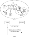
- FIG. 1 is a schematic diagram of an application scenario according to an embodiment of this application.
- An application system shown in FIG. 1 may include one network device and at least one terminal, and each terminal may communicate with the network device by using a radio signal.
- the terminal sends, to the network device in at least two time units, uplink signals that each include a DMRS.
- phase jump between the inconsecutive time units which may also be understood as that there may be a phase jump between the uplink signals carried in the inconsecutive time units; or if the at least two time units are consecutive in time domain, but symbols that are in the two consecutive time units and on which the DMRSs are located are inconsecutive, there may be a phase jump between the consecutive time units, which may also be understood as that there may be a phase jump between the uplink signals carried in the consecutive time units. Because the phase jump is random and uncontrollable, a phase difference between the DMRSs includes not only a phase rotation caused by a channel, but also an unknown phase rotation.
- a terminal receives configuration information of a first reference signal from a network device; and sends, based on the configuration information, uplink signals to the network device in at least two time units, where the uplink signals each include uplink data and the first reference signal.
- the first reference signal is carried on the last M symbols in symbols that are in a previous time unit (first time unit) and on which the uplink signal is located, and the first reference signal is carried on the first N symbols in symbols that are in a subsequent time unit (second time unit) and on which the uplink signal is located.
- a time unit may be a slot, or may be a hop (hop) in a slot.
- the time unit may be configured based on an actual requirement.
- the last M symbols in the first time unit that are used to carry the first reference signal are not the last M symbols in all symbols included in the entire first time unit, but are the last M symbols in symbols that are used to carry the uplink signal and that are in all the symbols included in the entire first time unit.
- the time unit is a slot, and the entire slot includes 14 symbols that can be used to carry the first reference signal.
- the uplink signal is carried on only 10 symbols in the middle of the 14 symbols.
- the last M symbols in the slot that are used to carry the first reference signal are not the last M symbols in the 14 symbols included in the entire slot, but are the last M symbols in the 10 symbols in the middle of the 14 symbols.
- the first N symbols in the second time unit that are used to carry the first reference signal are not the first N symbols in all symbols included in the entire second time unit, but are the first N symbols in symbols that are used to carry the uplink signal and that are in all the symbols included in the entire second time unit.
- M and N are integers greater than 1, and M may or may not be equal to N.
- both M and N are equal to 1
- the network device may determine that there is a small possibility that a channel changes sharply between the two symbols. Therefore, the network device may determine that there is a large possibility that there is a phase change in the first reference signals in the two time units. This further improves the probability of correctly determining, by the network device, whether there is a phase jump.
- Specific values of M and N may be configured by the network device for a terminal device, or may be determined in a predefined manner.
- the uplink signal sending method may be implemented by the network device, or may be implemented by a chip in the network device, for example, a baseband processor, or may be jointly implemented by a baseband processor and a radio frequency unit; or when the execution body is the terminal, the uplink signal sending method may be implemented by the terminal, or may be implemented by a chip in the terminal, for example, a baseband processor, or may be jointly implemented by a baseband processor and a radio frequency unit.
- the terminal sends the uplink signals to the network device in the two adjacent time units: the first time unit and the second time unit, in the two adjacent time units, the first reference signal is carried on the last M symbols in the symbols that are in the previous time unit and on which the uplink signal is located, and the first reference signal is carried on the first N symbols in the symbols that are in the subsequent time unit and on which the uplink signal is located.
- the first reference signal is carried on the last M symbols in the symbols that are in the previous time unit and on which the uplink signal is located
- the first reference signal is carried on the first N symbols in the symbols that are in the subsequent time unit and on which the uplink signal is located.
- the terminal sends the uplink signals to the network device in the two adjacent time units: the first time unit and the second time unit.
- the terminal sends the uplink signals to the network device in a non-frequency-hopping manner.
- a time unit is a slot.
- the terminal sends the uplink signals to the network device in a frequency hopping manner.
- the frequency hopping manner further includes an inter-slot frequency hopping manner and an intra-slot frequency hopping manner.
- a time unit is a slot or a hop in a slot.
- the terminal sends the uplink signals to the network device in the non-frequency-hopping manner.
- the first reference signal is a DMRS.
- FIG. 2 is a schematic flowchart of a reference signal sending method according to an embodiment of this application.
- the reference signal sending method may include the following steps.
- S201 A network device sends configuration information of a first reference signal to a terminal.
- the configuration information may include at least one of sequence indication information, time domain resource indication information, and frequency domain resource indication information.
- the sequence indication information is used to indicate a sequence corresponding to the first reference signal
- the time domain resource indication information is used to indicate a symbol that carries the first reference signal
- the frequency domain resource indication information is used to indicate a subcarrier that carries the first reference signal.
- the terminal After receiving the configuration information, of the first reference signal, sent by the network device, the terminal may determine the first reference signal based on the configuration information of the first reference signal. In this way, the terminal may send, to the network device within transmission duration, uplink signals that each include the first reference signal, that is, perform the following S202.
- S202 The terminal sends, based on the configuration information, the uplink signals to the network device within the transmission duration.
- the uplink signals each include uplink data and the first reference signal.
- the transmission duration includes a first time unit and a second time unit.
- the first time unit is adjacent to and located before the second time unit.
- the first reference signal is carried on the first N symbols in symbols that are in the second time unit and on which the uplink signal is located, and the first reference signal is carried on the last M symbols in symbols that are in the first time unit and on which the uplink signal is located.
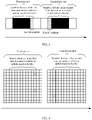
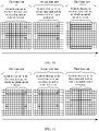
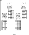
- FIG. 3 is a schematic diagram of two time units that carry first reference signals according to an embodiment of this application. N and M are integers greater than or equal to 1.
- the terminal needs to determine information in two aspects before sending, to the network device, the uplink signals that each include the uplink data and the first reference signal.
- the terminal needs to first generate the first reference information based on the received configuration information of the first reference signal.
- the terminal after generating the first reference signal and before sending the uplink signals that each include the first reference signal, the terminal needs to determine time domain resources and frequency domain resources occupied by the first reference signals. The following describes in detail how to determine the information in the two aspects.
- the terminal needs to first generate the first reference signal based on the received configuration information of the first reference signal.
- the terminal When the terminal generates the first reference signal based on the configuration information of the first reference signal, an example in which the first reference signal is a JD-RS is used.
- the configuration information, of the first reference signal, received by the terminal includes the sequence indication information, the terminal needs to generate the first reference signal based on the sequence indication information.
- the sequence indication information is an initial phase of the JD-RS
- the terminal may generate the JD-RS based on Gold sequence indication information; or when the sequence indication information is a root and a cyclic shift value of the JD-RS, the terminal may generate the JD-RS based on Zad-off Chu (ZC) sequence indication information.
- ZC Zad-off Chu
- the terminal may alternatively generate the JD-RS in another predefined manner.
- the first reference signal JD-RS is generated.
- a specific manner of generating the JD-RS based on the sequence indication information is not specifically limited in this embodiment of this application.
- the terminal determines the time domain resources and the frequency domain resources occupied by the first reference signals.
- the time domain resources occupied by the first reference signals may be the first N symbols in the symbols that are in the second time unit and on which the uplink signal is located and the last M symbols in the symbols that are in the first time unit and on which the uplink signal is located.
- the terminal determines the frequency domain resources occupied by the first reference signals usually, because the first reference signals are used to determine whether there is a phase jump between two slots, the first reference signals do not need to be used to estimate channels on all frequencies in a transmission process.
- K is an integer greater than or equal to 1.
- resource overheads of the JD-RSs can be reduced.
- K is equal to 6, to be specific, one first reference signal is set for every six subcarriers.
- K may alternatively be an integer multiple of 6.
- a value range of M is ⁇ 6, 12, 24, 36, ... ⁇ .
- An advantage is as follows: In all resource blocks (resource blocks, RBs) that carry the first reference signals, indexes of resource elements (resource elements, REs) occupied by the first reference signals are the same. This helps the network device use a same phase jump detection method on all the RBs.
- An RE may be defined as a symbol in time domain or a subcarrier in frequency domain.
- a frequency domain resource occupied by the M symbols may be different from a frequency domain resource occupied by the N symbols.
- a subcarrier in the M symbols that carries the first reference signal may be different from a subcarrier that carries the first reference signal and that is in the first N symbols in the second time unit.
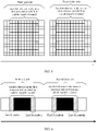
- FIG. 4 is another schematic diagram of two time units that carry first reference signals according to an embodiment of this application.
- FIG. 5 is still another schematic diagram of two time units that carry first reference signals according to an embodiment of this application.
- phase jump determining result is affected because the frequency of the subcarrier that carries the first reference signal and that is in the first time unit is different from the frequency of the subcarrier that carries the first reference signal and that is in the second time unit, thereby improving accuracy of determining whether there is a phase jump.
- the transmission duration includes two time units: the first time unit and the second time unit
- the first reference signal is carried on the last M symbols in the symbols that are in the first time unit and on which the uplink signal is located
- the first reference signal is carried on the first N symbols in the symbols that are in the second time unit and on which the uplink signal is located, as shown in FIG. 3 .
- the first reference signal may be carried only on the last M symbols in the symbols that are in the first time unit and on which the uplink signal is located, and the first reference signal may be carried only on the first N symbols in the symbols that are in the second time unit and on which the uplink signal is located, but the first reference signal is not carried on the first N symbols in the symbols that are in the first time unit and on which the uplink signal is located, and the first reference signal is not carried on the last M symbols in the symbols that are in the second time unit and on which the uplink signal is located, still as shown in FIG. 3 .
- the first reference signal may further be carried on the first N symbols in the symbols that are in the first time unit and on which the uplink signal is located, and the first reference signal may further be carried on the last M symbols in the symbols that are in the second time unit and on which the uplink signal is located, that is, the first reference signal is carried on the first N symbols in symbols that are in each time unit and on which the uplink signal is located, and the first reference signal is carried on the last M symbols in the symbols that are in each time unit and on which the uplink signal is located.
- the terminal does not need to distinguish between the first time unit and the second time unit, so that complexity of the terminal is reduced.
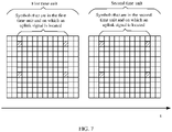
- FIG. 6 is yet another schematic diagram of two time units that carry first reference signals according to an embodiment of this application.
- a subcarrier that carries the first reference signal and that is in the first N symbols in the symbols that are in the first time unit and on which the uplink signal is located may be the same as a subcarrier that carries the first reference signal and that is in the last M symbols in the symbols that are in the first time unit and on which the uplink signal is located.
- FIG. 7 is a schematic diagram of two time units that carry first reference signals according to an embodiment of this application.
- the subcarrier that carries the first reference signal and that is in the first N symbols in the symbols that are in the first time unit and on which the uplink signal is located may alternatively be different from the subcarrier that carries the first reference signal and that is in the last M symbols in the symbols that are in the first time unit and on which the uplink signal is located.
- FIG. 8 is another schematic diagram of two time units that carry first reference signals according to an embodiment of this application.
- the subcarrier that carries the first reference signal and that is in the last M symbols in the symbols that are in the first time unit and on which the uplink signal is located is different from a subcarrier that carries the first reference signal and that is in the first N symbols in the symbols that are in the second time unit and on which the uplink signal is located
- the subcarrier that carries the first reference signal and that is in the last M symbols in the symbols that are in the first time unit and on which the uplink signal is located needs to be the same as the subcarrier that carries the first reference signal and that is in the first N symbols in the symbols that are in the second time unit and on which the uplink signal is located.
- the subcarrier that carries the first reference signal and that is in the first N symbols in the symbols that are in the second time unit and on which the uplink signal is located may alternatively be different from the subcarrier that carries the first reference signal and that is in the last M symbols in the symbols that are in the second time unit and on which the uplink signal is located, as shown in FIG. 8 .
- the network device may first determine, based on the two first reference signals having a small time interval, whether there is a phase jump. If the network device determines that there is no phase jump, the network device determines that joint channel estimation can be performed across time units. On the contrary, if the network device determines that there is a phase jump, the network device estimates a phase jump difference based on the two first reference signals having a small time interval and performs compensation, and then performs cross-time-unit joint channel estimation based on a compensation value and the two first reference signals having a small time interval. In this way, accuracy of determining whether cross-time-unit joint channel estimation can be performed across time units is improved.
- the transmission duration includes two adjacent time units: the first time unit and the second time unit.
- a quantity of time units in the transmission duration may be extended to L, and L is an integer greater than 2.
- L is equal to 3
- the transmission duration includes three adjacent time units.
- the three time units are sequentially a first time unit, a second time unit, and a third time unit.
- the terminal sends, to the network device within the transmission duration, the uplink signals that each include the uplink data and the first reference signal, at least two different implementations may be included.
- the first reference signals are carried on the first N symbols in symbols that are in the second time unit and the third time unit and on which the uplink signals are located, and the first reference signal is not carried in the first time unit; and the first reference signals are carried on the last M symbols in symbols that are in the first time unit and the second time unit and on which the uplink signals are located, and the first reference signal is not carried in the third time unit.
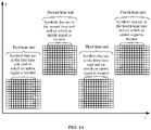
- FIG. 10 is a schematic diagram of three time units that carry first reference signals according to an embodiment of this application.
- the first reference signals may be carried on the first N symbols in symbols that are in the first time unit, the second time unit, and the third time unit and on which the uplink signals are located, and the first reference signals may be carried on the last M symbols in the symbols that are in the first time unit, the second time unit, and the third time unit and on which the uplink signals are located.
- the terminal does not need to distinguish between the first time unit, the second time unit, and the third time unit, so that complexity of the terminal is reduced.
- FIG. 11 is another schematic diagram of three time units that carry first reference signals according to an embodiment of this application.
- the first reference signals may be carried on the first N symbols in symbols that are in the first time unit, the second time unit, and the third time unit and on which the uplink signals are located, the first reference signals may be carried on the last M symbols in the symbols that are in the first time unit and the second time unit and on which the uplink signals are located, and the first reference signal may not be carried on the last M symbols in symbols that are in the third time unit and on which the uplink signal is located.
- FIG. 12 is still another schematic diagram of three time units that carry first reference signals according to an embodiment of this application.
- the transmission duration includes the three adjacent time units
- the three possible implementations are merely used as an example for description in embodiments of this application, but this does not mean that embodiments of this application are limited thereto.
- FIG. 13 is a yet another schematic diagram of three time units that carry first reference signals according to an embodiment of this application.
- the subcarrier that carries the first reference signal and that is in the first time unit is different from a frequency of the subcarrier that carries the first reference signal and that is in the second time unit
- the subcarrier that carries the first reference signal and that is in the last M symbols in the symbols that are in the first time unit and on which the uplink signal is located may be the same as the subcarrier that carries the first reference signal and that is in the first N symbols in the symbols that are in the second time unit and on which the uplink signal is located.
- FIG. 14 is a schematic diagram of three time units that carry first reference signals according to an embodiment of this application.
- phase jump determining result is affected because the frequency of the subcarrier that carries the first reference signal and that is in the first time unit is different from the frequency of the subcarrier that carries the first reference signal and that is in the second time unit, thereby improving accuracy of determining whether there is a phase jump.
- FIG. 15 is another schematic diagram of three time units that carry first reference signals according to an embodiment of this application.
- the subcarrier that carries the first reference signal and that is in the first time unit is different from a frequency of the subcarrier that carries the first reference signal and that is in the second time unit
- the subcarrier that carries the first reference signal and that is in the last M symbols in the symbols that are in the first time unit and on which the uplink signal is located may be the same as the subcarrier that carries the first reference signal and that is in the first N symbols in the symbols that are in the second time unit and on which the uplink signal is located.
- FIG. 16 is still another schematic diagram of three time units that carry first reference signals according to an embodiment of this application.
- the subcarrier that carries the first reference signal and that is in the last M symbols in the symbols that are in the second time unit and on which the uplink signal is located may be the same as the subcarrier that carries the first reference signal and that is in the first N symbols in the symbols that are in the third time unit and on which the uplink signal is located.
- phase jump determining result is affected because the frequency of the subcarrier that carries the first reference signal and that is in the first time unit is different from the frequency of the subcarrier that carries the first reference signal and that is in the second time unit, thereby improving accuracy of determining whether there is a phase jump.
- a symbol in which the DMRS is located is different from a symbol in which the first reference signal JD-RS is located. If a DMRS has been carried on a symbol, even if the network device configures a JD-RS for the terminal, the terminal does not send the JD-RS in the symbol in an actual uplink signal sending process. The reason is as follows: The network device may determine, by using the DMRS on the symbol, whether there is a phase jump on a channel. In this way, the JD-RS does not need to be sent, so that resources can be effectively saved. In addition, if the JD-RS is sent in the symbol that carries the DMRS, orthogonality of the DMRS may be damaged. Consequently, channel estimation quality is reduced.
- subcarriers on which the JD-RSs are located are some or all of subcarriers on which the DMRSs are located.
- an RE on which the JD-RS is located is also an RE on which the DMRS is located.
- REs on which the JD-RSs are located are the 2 nd RE and the 8 th RE
- REs on which the DMRSs are located are the 2 nd RE, the 4 th RE, the 6 th RE, the 8 th RE, the 10 th RE, and the 12 th RE.
- a benefit is as follows: If a JD-RS is not sent because a DMRS is carried on a symbol, the DMRS may replace the JD-RS on an RE, and be used together with a JD-RS on a same RE in an adjacent time unit to detect a phase jump.
- Embodiments shown in FIG. 2 to FIG. 16 describe in detail a technical solution in which a terminal sends uplink signals to a network device in a non-frequency-hopping manner in a possible scenario.
- the following describes in detail a technical solution in which a terminal sends uplink signals to a network device in a frequency hopping manner in another possible scenario.
- a first reference signal is a DMRS.
- FIG. 17 is a schematic flowchart of another reference signal sending method according to an embodiment of this application.
- the reference signal sending method may include the following steps.
- a network device sends configuration information of a first reference signal to a terminal.
- the configuration information may include at least one of sequence indication information, time domain resource indication information, and frequency domain resource indication information.
- the sequence indication information is used to indicate a sequence corresponding to the first reference signal
- the time domain resource indication information is used to indicate a symbol that carries the first reference signal
- the frequency domain resource indication information is used to indicate a subcarrier that carries the first reference signal.
- the terminal After receiving the configuration information, of the first reference signal, sent by the network device, the terminal may determine the first reference signal based on the configuration information of the first reference signal. In this way, the terminal may send, to the network device within transmission duration in a frequency hopping manner, uplink signals that each include the first reference signal, that is, perform the following S1702.
- S1702 The terminal sends, based on the configuration information, the uplink signals to the network device within the transmission duration in the frequency hopping manner.
- the uplink signals each include uplink data and the first reference signal.
- the transmission duration includes a first time unit, a second time unit, a third time unit, and a fourth time unit that are consecutive.
- a frequency domain resource occupied by the uplink signal in the first time unit is not exactly the same as a frequency domain resource occupied by the uplink signal in the second time unit.
- the frequency domain resource occupied by the uplink signal in the first time unit is the same as a frequency domain resource occupied by the uplink signal in the third time unit.
- the frequency domain resource occupied by the uplink signal in the second time unit is the same as a frequency domain resource occupied by the uplink signal in the fourth time unit.
- the first reference signals are carried on the last M symbols in symbols that are in the first time unit and the second time unit and on which the uplink signals are located.
- the first reference signals are further carried on the first N symbols in symbols that are in the third time unit and the fourth time unit and on which the uplink signals are located.
- a subcarrier that carries the first reference signal and that is in the last M symbols in the first time unit is the same as a subcarrier that carries the first reference signal and that is in the first N symbols in the third time unit.
- a subcarrier that carries the first reference signal and that is in the last M symbols in the second time unit is the same as a subcarrier that carries the first reference signal and that is in the first N symbols in the fourth time unit.
- N and M are integers greater than or equal to 1.
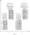
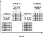
- FIG. 18 is a schematic diagram of four time units that carry first reference signals according to an embodiment of this application. If there is an intra-slot jump, a time unit is a hop in a slot.
- FIG. 19 is another schematic diagram of four time units that carry first reference signals according to an embodiment of this application.
- the subcarrier that carries the first reference signal and that is in the last M symbols in the first time unit is the same as the subcarrier that carries the first reference signal and that is in the first N symbols in the third time unit, as shown in FIG. 18 or FIG. 19 .
- phase jump determining result is affected because the frequency of the subcarrier that carries the first reference signal and that is in the first time unit is different from the frequency of the subcarrier that carries the first reference signal and that is in the third time unit, thereby improving accuracy of determining whether there is a phase jump.
- the subcarrier that carries the first reference signal and that is in the last M symbols in the second time unit is the same as the subcarrier that carries the first reference signal and that is in the first N symbols in the fourth time unit, still as shown in FIG. 18 or FIG. 19 .
- the phase jump determining result is affected because the frequency of the subcarrier that carries the first reference signal and that is in the second time unit is different from the frequency of the subcarrier that carries the first reference signal and that is in the fourth time unit, thereby improving accuracy of determining whether there is a phase jump.
- the subcarrier that carries the first reference signal and that is in the last M symbols in the first time unit may be different from the subcarrier that carries the first reference signal and that is in the first N symbols in the third time unit.
- the subcarrier that carries the first reference signal and that is in the last M symbols in the second time unit may also be different from the subcarrier that carries the first reference signal and that is in the first N symbols in the fourth time unit.
- the terminal needs to determine information in two aspects before sending, to the network device within the transmission duration in the frequency hopping manner, the uplink signals that each include the uplink data and the first reference signal.
- the terminal needs to first generate the first reference information based on the received configuration information of the first reference signal.
- the terminal after generating the first reference signal and before sending, to the network device within the transmission duration in the frequency hopping manner, the uplink signals that each include the first reference signal, the terminal needs to determine time domain resources and frequency domain resources occupied by the first reference signals. The following describes in detail how to determine the information in the two aspects.
- the terminal needs to first generate the first reference signal based on the received configuration information of the first reference signal.
- the terminal When the terminal generates the first reference signal based on the configuration information of the first reference signal, an example in which the first reference signal is a JD-RS is used.
- a method for generating the JD-RS is similar to the method for generating the JD-RS in the embodiment shown in FIG. 2 .
- S202 Details are not described herein again.
- the terminal determines the time domain resources and the frequency domain resources occupied by the first reference signals.
- the time domain resources occupied by the first reference signals may be the last M symbols in the symbols that are in the first time unit and the second time unit and on which the uplink signals are located and the first N symbols in the symbols that are in the third time unit and the fourth time unit and on which the uplink signals are located.
- the terminal determines the frequency domain resources occupied by the first reference signals usually, because the first reference signals are used to determine whether there is a phase jump between two slots, the first reference signals do not need to be used to estimate channels on all frequencies in a transmission process.
- an interval between any two adjacent subcarriers occupied by the first reference signals is K subcarriers, that is, one first reference signal is set for every K subcarriers.
- K is an integer greater than or equal to 1.
- resource overheads of the JD-RSs can be reduced.
- K is equal to 6, to be specific, one first reference signal is set for every six subcarriers.
- K may alternatively be an integer multiple of 6.
- a value range of M is ⁇ 6, 12, 24, 36, ... ⁇ .
- a frequency domain resource occupied by the M symbols may be the same as a frequency domain resource occupied by the N symbols.
- the subcarrier in the M symbols that carries the first reference signal is the same as the subcarrier that carries the first reference signal and that is in the first N symbols in the second time unit, as shown in FIG. 18 or FIG. 19 .
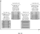
- FIG. 20 is still another schematic diagram of four time units that carry first reference signals according to an embodiment of this application.
- FIG. 21 is yet another schematic diagram of four time units that carry first reference signals according to an embodiment of this application.
- the transmission duration includes two time units: the first time unit and the second time unit
- the first reference signals are carried on the last M symbols in the symbols that are in the first time unit and the second time unit and on which the uplink signals are located
- the first reference signals are carried on the first N symbols in the symbols that are in the third time unit and the fourth time unit and on which the uplink signals are located, as shown in FIG. 18 or FIG. 19 .
- first reference signals are carried on the first N symbols in the symbols that are in the first time unit and the second time unit and on which the uplink signals are located and whether the first reference signals are carried on the last M symbols in the symbols that are in the third time unit and the fourth time unit and on which the uplink signals are located.
- the first reference signals may be carried on the first N symbols in the symbols that are in the first time unit, the second time unit, the third time unit, and the fourth time unit and on which the uplink signals are located, that is, the first reference signal is carried on the first N symbols in symbols that are in each time unit and on which the uplink signal is located, and the first reference signal is carried on the last M symbols in the symbols that are in each time unit and on which the uplink signal is located.
- the terminal does not need to distinguish between the first time unit, the second time unit, the third time unit, and the fourth time unit, so that complexity of the terminal is reduced.
- FIG. 22 is a schematic diagram of four time units that carry first reference signals according to an embodiment of this application.
- FIG. 23 is another schematic diagram of four time units that carry first reference signals according to an embodiment of this application.
- a subcarrier that carries the first reference signal and that is in the first N symbols in the symbols that are in the first time unit and on which the uplink signal is located may be the same as a subcarrier that carries the first reference signal and that is in the last M symbols in the symbols that are in the first time unit and on which the uplink signal is located, as shown in FIG. 22 or FIG. 23 .
- the subcarrier that carries the first reference signal and that is in the first N symbols in the symbols that are in the first time unit and on which the uplink signal is located may alternatively be different from the subcarrier that carries the first reference signal and that is in the last M symbols in the symbols that are in the first time unit and on which the uplink signal is located.
- FIG. 24 is still another schematic diagram of four time units that carry first reference signals according to an embodiment of this application.
- FIG. 25 is yet another schematic diagram of four time units that carry first reference signals according to an embodiment of this application.
- the subcarrier that carries the first reference signal and that is in the last M symbols in the symbols that are in the first time unit and on which the uplink signal is located is different from the subcarrier that carries the first reference signal and that is in the first N symbols in the symbols that are in the third time unit and on which the uplink signal is located
- the subcarrier that carries the first reference signal and that is in the last M symbols in the symbols that are in the first time unit and on which the uplink signal is located needs to be the same as the subcarrier that carries the first reference signal and that is in the first N symbols in the symbols that are in the third time unit and on which the uplink signal is located.
- a subcarrier that carries the first reference signal and that is in the first N symbols in the symbols that are in the second time unit and on which the uplink signal is located may be the same as a subcarrier that carries the first reference signal and that is in the last M symbols in the symbols that are in the fourth time unit and on which the uplink signal is located, as shown in FIG. 22 or FIG. 23 .
- the subcarrier that carries the first reference signal and that is in the first N symbols in the symbols that are in the second time unit and on which the uplink signal is located may alternatively be different from the subcarrier that carries the first reference signal and that is in the last M symbols in the symbols that are in the fourth time unit and on which the uplink signal is located, as shown in FIG. 24 or FIG. 25 .
- the subcarrier that carries the first reference signal and that is in the last M symbols in the symbols that are in the second time unit and on which the uplink signal is located is different from the subcarrier that carries the first reference signal and that is in the first N symbols in the symbols that are in the fourth time unit and on which the uplink signal is located
- the subcarrier that carries the first reference signal and that is in the last M symbols in the symbols that are in the second time unit and on which the uplink signal is located needs to be the same as the subcarrier that carries the first reference signal and that is in the first N symbols in the symbols that are in the fourth time unit and on which the uplink signal is located.
- the uplink signal sending method is not limited to being applied to four time units scheduled by using a same piece of DCI, and may be further extended to four time units scheduled by using a plurality pieces of DCI.
- the first time unit may be the 1 st time unit scheduled by using second DCI. Because the first reference signal is carried on the first N symbols in the symbols that are in the first time unit and on which the uplink signal is located, and the first reference signal is carried on the last M symbols in symbols on which the uplink signal is located and that are in the last time unit that is scheduled by using first DCI and that is located before the first time unit, whether there is a phase jump between uplink transmission scheduled by using the two pieces of DCI may be determined based on the first reference signal carried on the last M symbols in the symbols on which the uplink signal is located and that are in the last time unit scheduled by using the first DCI and the first reference signal carried on the first N symbols in the symbols on which the uplink signal is located and that are in the first time unit scheduled by using the second DCI, and whether channel estimation can be performed across time units is determined based on a determining result. In this way, channel estimation is performed across time units scheduled by using different DCI.
- the terminal may include the first reference signals in the last M symbols in the symbols that are in the first time unit and the second time unit and on which the uplink signals are located, include the first reference signals in the first N symbols in the symbols that are in the third time unit and the fourth time unit and on which the uplink signals are located, and separately send, to the network device in the first time unit, the second time unit, the third time unit, and the fourth time unit in the frequency hopping manner, the uplink signals that each include the uplink data and the first reference signal.
- the network device may perform cross-time-unit joint channel estimation on the first time unit and the third time unit based on the first reference signal carried in the first time unit and the first reference signal carried in the third time unit, where a time interval between the two first reference signals is small; and may perform cross-time-unit joint channel estimation on the second time unit and the fourth time unit based on the first reference signal carried in the second time unit and the first reference signal carried in the fourth time unit, where a time interval between the two first reference signals is small.
- the network device may first determine, based on the two first reference signals having a small time interval, whether there is a phase jump. If the network device determines that there is no phase jump, the network device determines that joint channel estimation can be performed across time units.
- the network device determines that there is a phase jump, the network device estimates a phase jump difference based on the two first reference signals having a small time interval and performs compensation, and then performs cross-time-unit joint channel estimation based on a compensation value and the two first reference signals having a small time interval. In this way, accuracy of determining whether cross-time-unit joint channel estimation can be performed across time units is improved.
- the first reference signal is the DMRS
- the first reference signal is a reference signal different from the DMRS, for example, a JD-RS signal
- a difference from the foregoing embodiments in which the first reference signal is the DMRS is: The last M symbols that are used to carry the JD-RS and that are in the symbols that are in the first time unit and on which the uplink signal is located and the first N symbols that are used to carry the JD -RS and that are in the symbols that are in the second time unit and on which the uplink signal is located are jointly determined based on other reference signals, for example, symbols on which DMRSs are currently located.
- a symbol in which the DMRS is located is different from a symbol in which the first reference signal JD-RS is located. If a DMRS has been carried on a symbol, even if the network device configures a JD-RS for the terminal, the terminal does not send the JD-RS in the symbol in an actual uplink signal sending process. The reason is as follows: The network device may determine, by using the DMRS on the symbol, whether there is a phase jump on a channel. In this way, the JD-RS does not need to be sent, so that resources can be effectively saved. In addition, if the JD-RS is sent in the symbol that carries the DMRS, orthogonality of the DMRS may be damaged. Consequently, channel estimation quality is reduced.
- subcarriers on which the JD-RSs are located are some or all of subcarriers on which the DMRSs are located.
- an RE on which the JD-RS is located is also an RE on which the DMRS is located.
- REs on which the JD-RSs are located are the 2 nd RE and the 8 th RE
- REs on which the DMRSs are located are the 2 nd RE, the 4 th RE, the 6 th RE, the 8 th RE, the 10 th RE, and the 12 th RE.
- a benefit is as follows: If a JD-RS is not sent because a DMRS is carried on a symbol, the DMRS may replace the JD-RS on an RE, and be used together with a JD-RS on a same RE in an adjacent time unit to detect a phase jump.
- the first reference signal is carried on the first N symbols in symbols that are in each time unit in the transmission duration and on which the uplink signal is located, and the first reference signal is carried on the last M symbols in the symbols that are in each time unit in the transmission duration and on which the uplink signal is located.
- the transmission duration includes L time units, and L is an integer greater than 1.
- the first reference signal is carried on the first N symbols in symbols that are in each of the last L-1 time units and on which the uplink signal is located, and the first reference signal is not carried in the 1 st time unit in the L time units; and the first reference signal is carried on the last M symbols in symbols that are in each of the first L-1 time units and on which the uplink signal is located, and the first reference signal is not carried in the last time unit in the L time units.
- an interval between any two adjacent subcarriers occupied by the first reference signals is K subcarriers, and K is an integer greater than or equal to 1.
- a subcarrier that carries the first reference signal and that is in the last M symbols in the first time unit is the same as a subcarrier that carries the first reference signal and that is in the first N symbols in the second time unit.
- the reference signal sending apparatus 260 in the embodiment shown in FIG. 26 may be a terminal, or may be a component (for example, a chip or a circuit) that can be configured in the terminal.
- the reference signal sending apparatus 260 shown in this embodiment of this application may perform the reference signal sending method on the terminal side in embodiments shown in FIG. 2 to FIG. 16 .
- Implementation principles and beneficial effects of the reference signal sending apparatus 260 are similar to implementation principles and beneficial effects of the reference signal sending method on the terminal side. Details are not described herein again.
- FIG. 27 is a schematic diagram of a structure of another reference signal sending apparatus 270 according to an embodiment of this application.
- the reference signal sending apparatus 270 may include:
- a time unit is a hop in a slot.
- a time unit is a slot.
- the configuration information includes at least one of sequence indication information, time domain resource indication information, and frequency domain resource indication information.
- the sequence indication information is used to indicate a sequence corresponding to the first reference signal
- the time domain resource indication information is used to indicate a symbol that carries the first reference signal
- the frequency domain resource indication information is used to indicate a subcarrier that carries the first reference signal.
- the reference signal sending apparatus 270 in the embodiment shown in FIG. 27 may be a terminal, or may be a component (for example, a chip or a circuit) that can be configured in the terminal.
- the reference signal sending apparatus 270 shown in this embodiment of this application may perform the reference signal sending method on the terminal side in embodiments shown in FIG. 17 to FIG. 25 .
- Implementation principles and beneficial effects of the reference signal sending apparatus 270 are similar to implementation principles and beneficial effects of the reference signal sending method on the terminal side. Details are not described herein again.
- FIG. 28 is a schematic diagram of a structure of a reference signal receiving apparatus 280 according to an embodiment of this application.
- the reference signal receiving apparatus 280 may include:
- the first reference signal is carried on the first N symbols in symbols that are in each of the at least two time units and on which the uplink signal is located, and the first reference signal is carried on the last M symbols in the symbols that are in each of the at least two time units and on which the uplink signal is located.
- the at least two time units include L time units, and L is an integer greater than 1.
- the first reference signal is carried on the first N symbols in symbols that are in each of the last L-1 time units and on which the uplink signal is located, and the first reference signal is not carried in the 1 st time unit in the L time units; and the first reference signal is carried on the last M symbols in symbols that are in each of the first L-1 time units and on which the uplink signal is located, and the first reference signal is not carried in the last time unit in the L time units.
- an interval between any two adjacent subcarriers occupied by the first reference signals is K subcarriers, and K is an integer greater than or equal to 1.
- a subcarrier that carries the first reference signal and that is in the last M symbols in the first time unit is the same as a subcarrier that carries the first reference signal and that is in the first N symbols in the second time unit.
- the reference signal receiving apparatus 280 in the embodiment shown in FIG. 28 may be a terminal, or may be a component (for example, a chip or a circuit) that can be configured in the terminal.
- the reference signal receiving apparatus 280 shown in this embodiment of this application may perform the reference signal receiving method on the terminal side in embodiments shown in FIG. 2 to FIG. 16 .
- Implementation principles and beneficial effects of the reference signal receiving apparatus 280 are similar to implementation principles and beneficial effects of the reference signal receiving method on the terminal side. Details are not described herein again.
- FIG. 29 is a schematic diagram of a structure of a reference signal receiving apparatus 290 according to an embodiment of this application.
- the reference signal receiving apparatus 290 may include:
- a time unit is a slot.
- the configuration information includes at least one of sequence indication information, time domain resource indication information, and frequency domain resource indication information.
- the sequence indication information is used to indicate a sequence corresponding to the first reference signal
- the time domain resource indication information is used to indicate a symbol that carries the first reference signal
- the frequency domain resource indication information is used to indicate a subcarrier that carries the first reference signal.
- the reference signal receiving apparatus 290 further includes a processing unit 2903.
- the processing unit 2903 is configured to perform joint channel estimation based on the first reference signals.
- the reference signal receiving apparatus 290 in the embodiment shown in FIG. 29 may be a terminal, or may be a component (for example, a chip or a circuit) that can be configured in the terminal.
- the reference signal receiving apparatus 290 shown in this embodiment of this application may perform the reference signal receiving method on the terminal side in embodiments shown in FIG. 15 to FIG. 17 .
- Implementation principles and beneficial effects of the reference signal receiving apparatus 290 are similar to implementation principles and beneficial effects of the reference signal receiving method on the terminal side. Details are not described herein again.
- An embodiment of this application further provides a communication system.
- the communication system may include the reference signal sending apparatus shown in FIG. 26 and the reference signal receiving apparatus shown in FIG. 28 ; or may include the reference signal sending apparatus shown in FIG. 27 and the reference signal receiving apparatus shown in FIG. 29 .
- Implementation principles and beneficial effects of the reference signal sending apparatus and the reference signal receiving apparatus are similar to implementation principles and beneficial effects of the reference signal sending method and the reference signal receiving method. Details are not described herein again.
- An embodiment of this application further provides a readable storage medium.
- the readable storage medium stores a computer program.
- the computer program When the computer program is executed, the computer program is used to perform a technical solution of the reference signal sending method on a terminal side in any one of the foregoing embodiments.
- An implementation principle and beneficial effects of the method are similar to an implementation principle and beneficial effects of the reference signal sending method. Details are not described herein again.
- the computer program when the computer program is executed, the computer program is used to perform a technical solution of the reference signal receiving method on a network device side in any one of the foregoing embodiments.
- An implementation principle and beneficial effects of the method are similar to an implementation principle and beneficial effects of the reference signal receiving method. Details are not described herein again.
- the processor in the foregoing embodiments may be a general-purpose processor, a digital signal processor (digital signal processor, DSP), an application-specific integrated circuit (application-specific integrated circuit, ASIC), a field programmable gate array (field programmable gate array, FPGA) or another programmable logic device, a discrete gate or a transistor logic device, or a discrete hardware component.
- the processor may implement or perform the methods, the steps, and logical block diagrams that are disclosed in embodiments of this application.
- the general-purpose processor may be a microprocessor, or the processor may be any conventional processor or the like.
- the steps in the methods disclosed with reference to embodiments of this application may be directly performed and completed through a hardware decoding processor, or may be performed and completed through a combination of hardware in the decoding processor and a software module.
- the software module may be located in a mature storage medium in the art, such as a random access memory (random access memory, RAM), a flash memory, a read-only memory (read-only memory, ROM), a programmable read-only memory, an electrically erasable programmable memory, or a register.
- the storage medium is located in the memory, and a processor reads instructions in the memory and completes the steps in the foregoing methods in combination with hardware of the processor.
- the disclosed apparatus and method may be implemented in other manners.
- the described apparatus embodiment is merely an example.
- division into the units is merely logical function division and may be other division during actual implementation.
- a plurality of units or components may be combined or integrated into another system, or some features may be ignored or not performed.
- the displayed or discussed mutual couplings or direct couplings or communication connections may be implemented through some interfaces.
- the indirect couplings or communication connections between the apparatuses or units may be implemented in electronic, mechanical, or other forms.
- functional units in embodiments of this application may be integrated into one processing unit, or each of the units may exist alone physically, or two or more units are integrated into one unit.
- the integrated unit may be implemented in a form of hardware, or may be implemented in a form of hardware combined with a software functional unit.
Landscapes
- Engineering & Computer Science (AREA)
- Signal Processing (AREA)
- Computer Networks & Wireless Communication (AREA)
- Mobile Radio Communication Systems (AREA)
Applications Claiming Priority (1)
| Application Number | Priority Date | Filing Date | Title |
|---|---|---|---|
| PCT/CN2019/107121 WO2021051416A1 (fr) | 2019-09-20 | 2019-09-20 | Procédé d'envoi d'un signal de référence, procédé, appareil et système de réception d'un signal de référence |
Publications (3)
| Publication Number | Publication Date |
|---|---|
| EP4024993A1 true EP4024993A1 (fr) | 2022-07-06 |
| EP4024993A4 EP4024993A4 (fr) | 2022-09-07 |
| EP4024993B1 EP4024993B1 (fr) | 2026-04-22 |
Family
ID=74884270
Family Applications (1)
| Application Number | Title | Priority Date | Filing Date |
|---|---|---|---|
| EP19946009.8A Active EP4024993B1 (fr) | 2019-09-20 | 2019-09-20 | Procédé d'envoi d'un signal de référence, procédé, appareil et système de réception d'un signal de référence |
Country Status (4)
| Country | Link |
|---|---|
| US (1) | US12267274B2 (fr) |
| EP (1) | EP4024993B1 (fr) |
| CN (1) | CN114402686B (fr) |
| WO (1) | WO2021051416A1 (fr) |
Families Citing this family (4)
| Publication number | Priority date | Publication date | Assignee | Title |
|---|---|---|---|---|
| EP4061075A4 (fr) * | 2019-12-12 | 2022-11-30 | Huawei Technologies Co., Ltd. | Procédé et appareil de communication sans fil |
| US20240214167A1 (en) * | 2021-08-06 | 2024-06-27 | Nokia Technologies Oy | Phase continuity tracking |
| CN117375781B (zh) * | 2022-06-30 | 2026-01-27 | 华为技术有限公司 | 一种参考信号的指示方法及装置 |
| CN115811452B (zh) * | 2022-11-23 | 2024-08-06 | 哲库科技(北京)有限公司 | 下行控制信道的信道估计方法、装置、设备及存储介质 |
Family Cites Families (20)
| Publication number | Priority date | Publication date | Assignee | Title |
|---|---|---|---|---|
| US8514768B2 (en) * | 2008-12-11 | 2013-08-20 | Lg Electronics Inc. | Method and apparatus for transmitting reference signal performed by relay station in wireless communication system |
| CN102437987B (zh) * | 2010-09-29 | 2015-09-16 | 中兴通讯股份有限公司 | 信道状态信息参考信号序列的生成和映射方法及装置 |
| CN106506111A (zh) * | 2015-09-06 | 2017-03-15 | 上海朗帛通信技术有限公司 | 一种无线通信中的参考信号设计方法和装置 |
| WO2017075807A1 (fr) * | 2015-11-06 | 2017-05-11 | 华为技术有限公司 | Procédé de transmission de données, dispositif de réseau et dispositif de terminal |
| US10085256B2 (en) * | 2016-02-16 | 2018-09-25 | Qualcomm Incorporated | Downlink operations with shortened transmission time intervals |
| US11026251B2 (en) * | 2016-05-12 | 2021-06-01 | Sharp Kabushiki Kaisha | Base station apparatus, terminal apparatus, and communication method therefor |
| CN107404370B (zh) * | 2016-05-18 | 2021-02-12 | 华为技术有限公司 | 参考信号配置方法及装置 |
| CN107689845B (zh) * | 2016-08-05 | 2023-07-18 | 华为技术有限公司 | 一种传输参考信号的方法、相关设备及通信系统 |
| US11071136B2 (en) * | 2016-08-25 | 2021-07-20 | Huawei Technologies Co., Ltd. | System and method for multiplexing traffic |
| CN110169002B (zh) * | 2017-01-09 | 2021-11-30 | Lg 电子株式会社 | 无线通信系统中发送参考信号的方法及其装置 |
| CN109150387B (zh) * | 2017-06-16 | 2023-04-28 | 华为技术有限公司 | 发送参考信号的方法、接收参考信号的方法和通信装置 |
| CN109274471B (zh) * | 2017-07-17 | 2024-01-02 | 华为技术有限公司 | 用于传输dmrs的方法和通信设备 |
| CN109802810B (zh) * | 2017-11-17 | 2021-07-09 | 华为技术有限公司 | 发送探测参考信号srs的方法和装置 |
| CN111034310A (zh) * | 2018-08-03 | 2020-04-17 | Lg电子株式会社 | 发送或接收参考信号的方法及设备 |
| CN111066363B (zh) * | 2018-08-07 | 2023-04-18 | Lg电子株式会社 | 节点在无线通信系统中的资源使用方法和使用该方法的装置 |
| WO2020032683A1 (fr) * | 2018-08-09 | 2020-02-13 | 엘지전자 주식회사 | Procédé d'émission et de réception d'un signal dans un système de communication sans fil permettant de prendre en charge une bande sans licence, et dispositif prenant en charge une bande sans licence |
| WO2020091559A1 (fr) * | 2018-11-02 | 2020-05-07 | 엘지전자 주식회사 | Procédé et dispositif pour la transmission et la réception de signaux dans un système de communication sans fil |
| WO2020171677A1 (fr) * | 2019-02-22 | 2020-08-27 | 엘지전자 주식회사 | Procédé et dispositif de transmission et de réception d'un signal sans fil dans un système de communication sans fil |
| CN113785527B (zh) * | 2019-05-03 | 2024-09-27 | Lg电子株式会社 | 发送pusch的方法、用户设备、设备和存储介质以及接收pusch的方法和基站 |
| US11456817B2 (en) * | 2019-08-15 | 2022-09-27 | Lg Electronics Inc. | Method and apparatus for transmitting and receiving signal in wireless communication system |
-
2019
- 2019-09-20 EP EP19946009.8A patent/EP4024993B1/fr active Active
- 2019-09-20 WO PCT/CN2019/107121 patent/WO2021051416A1/fr not_active Ceased
- 2019-09-20 CN CN201980100350.6A patent/CN114402686B/zh active Active
-
2022
- 2022-03-18 US US17/698,001 patent/US12267274B2/en active Active
Also Published As
| Publication number | Publication date |
|---|---|
| US20220209922A1 (en) | 2022-06-30 |
| CN114402686A (zh) | 2022-04-26 |
| EP4024993A4 (fr) | 2022-09-07 |
| US12267274B2 (en) | 2025-04-01 |
| EP4024993B1 (fr) | 2026-04-22 |
| CN114402686B (zh) | 2024-11-15 |
| WO2021051416A1 (fr) | 2021-03-25 |
Similar Documents
| Publication | Publication Date | Title |
|---|---|---|
| US12267274B2 (en) | Reference signal sending method, reference signal receiving method, apparatus, and system | |
| US20250286676A1 (en) | Method for configuring positioning reference signal in nr system, method for receiving positioning reference signal in nr system, and device | |
| WO2020164617A1 (fr) | Procédé d'envoi de signal, procédé de réception de signal, dispositif de réseau et terminal | |
| US7961709B2 (en) | Secondary synchronization sequences for cell group detection in a cellular communications system | |
| US20230121167A1 (en) | Interference rejection combining method, resource indication method, and communication apparatus | |
| CN101292461B (zh) | 提供初始小区捕获和导频序列检测的装置、方法和计算机程序产品 | |
| JP7575595B2 (ja) | 同期信号ブロックの伝送方法、装置、機器及び記憶媒体 | |
| WO2020142999A1 (fr) | Bloc de signal de synchronisation de liaison latérale nr v2x | |
| US11910340B2 (en) | Method and apparatus for establishing a set of a plurality of synchronization signal sequences to be used with one or more communication targets | |
| US11405936B2 (en) | Scheduling timing determination method, terminal and network side device | |
| CN116114337B (zh) | 一种物理下行控制信道传输方法及装置 | |
| US11191066B2 (en) | Method for transmitting data, terminal device and network device | |
| US12132570B2 (en) | Sequence-based signal transmission method and communication apparatus | |
| EP3609227A1 (fr) | Procédé, dispositif de réseau et dispositif terminal permettant d'émettre un signal | |
| US9094146B2 (en) | Secondary synchronization sequences for cell group detection in a cellular communications system | |
| EP3609255A1 (fr) | Procédé et appareil de traitement du signal | |
| US20250184054A1 (en) | Reference signal transmission method and communication apparatus | |
| US20250226953A1 (en) | Communication method and communication apparatus | |
| CN112332957B (zh) | 一种传输信息的方法和装置 | |
| WO2025124137A1 (fr) | Procédé et appareil de transmission de signal | |
| WO2019033392A1 (fr) | Procédé d'émission de signal, dispositif terminal et dispositif réseau | |
| WO2017114050A1 (fr) | Procédé d'émission et procédé de réception pour signal de référence de démodulation, dispositif de terminal et station de base | |
| WO2024067598A1 (fr) | Procédé et appareil de modulation, procédé et appareil de démodulation, et dispositif, système et support de stockage | |
| WO2019109344A1 (fr) | Commande de diversité de retard cyclique flexible dans des scénarios de v2x | |
| CN110719152A (zh) | 一种上行发送方法和发送端 |
Legal Events
| Date | Code | Title | Description |
|---|---|---|---|
| STAA | Information on the status of an ep patent application or granted ep patent |
Free format text: STATUS: THE INTERNATIONAL PUBLICATION HAS BEEN MADE |
|
| PUAI | Public reference made under article 153(3) epc to a published international application that has entered the european phase |
Free format text: ORIGINAL CODE: 0009012 |
|
| STAA | Information on the status of an ep patent application or granted ep patent |
Free format text: STATUS: REQUEST FOR EXAMINATION WAS MADE |
|
| 17P | Request for examination filed |
Effective date: 20220330 |
|
| AK | Designated contracting states |
Kind code of ref document: A1 Designated state(s): AL AT BE BG CH CY CZ DE DK EE ES FI FR GB GR HR HU IE IS IT LI LT LU LV MC MK MT NL NO PL PT RO RS SE SI SK SM TR |
|
| A4 | Supplementary search report drawn up and despatched |
Effective date: 20220804 |
|
| RIC1 | Information provided on ipc code assigned before grant |
Ipc: H04W 72/12 20090101AFI20220729BHEP |
|
| DAV | Request for validation of the european patent (deleted) | ||
| DAX | Request for extension of the european patent (deleted) | ||
| STAA | Information on the status of an ep patent application or granted ep patent |
Free format text: STATUS: EXAMINATION IS IN PROGRESS |
|
| 17Q | First examination report despatched |
Effective date: 20250507 |
|
| REG | Reference to a national code |
Ref country code: DE Ref legal event code: R079 Free format text: PREVIOUS MAIN CLASS: H04W0072120000 Ipc: H04L0005000000 Ref document number: 602019084066 Country of ref document: DE |
|
| GRAP | Despatch of communication of intention to grant a patent |
Free format text: ORIGINAL CODE: EPIDOSNIGR1 |
|
| STAA | Information on the status of an ep patent application or granted ep patent |
Free format text: STATUS: GRANT OF PATENT IS INTENDED |
|
| RIC1 | Information provided on ipc code assigned before grant |
Ipc: H04W 72/12 20090101AFI20251113BHEP Ipc: H04L 5/00 20060101ALI20251113BHEP Ipc: H04L 25/03 20060101ALI20251113BHEP Ipc: H04L 27/26 20060101ALI20251113BHEP Ipc: H04L 25/02 20060101ALN20251113BHEP |
|
| RIC1 | Information provided on ipc code assigned before grant |
Ipc: H04L 5/00 20060101AFI20251126BHEP Ipc: H04L 25/03 20060101ALI20251126BHEP Ipc: H04L 27/26 20060101ALI20251126BHEP Ipc: H04L 25/02 20060101ALN20251126BHEP |
|
| INTG | Intention to grant announced |
Effective date: 20251211 |
|
| GRAS | Grant fee paid |
Free format text: ORIGINAL CODE: EPIDOSNIGR3 |
|
| GRAA | (expected) grant |
Free format text: ORIGINAL CODE: 0009210 |
|
| STAA | Information on the status of an ep patent application or granted ep patent |
Free format text: STATUS: THE PATENT HAS BEEN GRANTED |
|
| AK | Designated contracting states |
Kind code of ref document: B1 Designated state(s): AL AT BE BG CH CY CZ DE DK EE ES FI FR GB GR HR HU IE IS IT LI LT LU LV MC MK MT NL NO PL PT RO RS SE SI SK SM TR |
|
| REG | Reference to a national code |
Ref country code: CH Ref legal event code: F10 Free format text: ST27 STATUS EVENT CODE: U-0-0-F10-F00 (AS PROVIDED BY THE NATIONAL OFFICE) Effective date: 20260422 Ref country code: GB Ref legal event code: FG4D |