EP4025468B1 - Dispositif de commande prédictif du mouvement d'un véhicule automobile - Google Patents
Dispositif de commande prédictif du mouvement d'un véhicule automobile Download PDFInfo
- Publication number
- EP4025468B1 EP4025468B1 EP20764400.6A EP20764400A EP4025468B1 EP 4025468 B1 EP4025468 B1 EP 4025468B1 EP 20764400 A EP20764400 A EP 20764400A EP 4025468 B1 EP4025468 B1 EP 4025468B1
- Authority
- EP
- European Patent Office
- Prior art keywords
- vehicle
- future
- control
- lateral
- states
- Prior art date
- Legal status (The legal status is an assumption and is not a legal conclusion. Google has not performed a legal analysis and makes no representation as to the accuracy of the status listed.)
- Active
Links
Images


Classifications
-
- B—PERFORMING OPERATIONS; TRANSPORTING
- B60—VEHICLES IN GENERAL
- B60W—CONJOINT CONTROL OF VEHICLE SUB-UNITS OF DIFFERENT TYPE OR DIFFERENT FUNCTION; CONTROL SYSTEMS SPECIALLY ADAPTED FOR HYBRID VEHICLES; ROAD VEHICLE DRIVE CONTROL SYSTEMS FOR PURPOSES NOT RELATED TO THE CONTROL OF A PARTICULAR SUB-UNIT
- B60W10/00—Conjoint control of vehicle sub-units of different type or different function
- B60W10/18—Conjoint control of vehicle sub-units of different type or different function including control of braking systems
-
- B—PERFORMING OPERATIONS; TRANSPORTING
- B60—VEHICLES IN GENERAL
- B60W—CONJOINT CONTROL OF VEHICLE SUB-UNITS OF DIFFERENT TYPE OR DIFFERENT FUNCTION; CONTROL SYSTEMS SPECIALLY ADAPTED FOR HYBRID VEHICLES; ROAD VEHICLE DRIVE CONTROL SYSTEMS FOR PURPOSES NOT RELATED TO THE CONTROL OF A PARTICULAR SUB-UNIT
- B60W10/00—Conjoint control of vehicle sub-units of different type or different function
- B60W10/18—Conjoint control of vehicle sub-units of different type or different function including control of braking systems
- B60W10/184—Conjoint control of vehicle sub-units of different type or different function including control of braking systems with wheel brakes
-
- B—PERFORMING OPERATIONS; TRANSPORTING
- B60—VEHICLES IN GENERAL
- B60W—CONJOINT CONTROL OF VEHICLE SUB-UNITS OF DIFFERENT TYPE OR DIFFERENT FUNCTION; CONTROL SYSTEMS SPECIALLY ADAPTED FOR HYBRID VEHICLES; ROAD VEHICLE DRIVE CONTROL SYSTEMS FOR PURPOSES NOT RELATED TO THE CONTROL OF A PARTICULAR SUB-UNIT
- B60W10/00—Conjoint control of vehicle sub-units of different type or different function
- B60W10/20—Conjoint control of vehicle sub-units of different type or different function including control of steering systems
-
- B—PERFORMING OPERATIONS; TRANSPORTING
- B60—VEHICLES IN GENERAL
- B60W—CONJOINT CONTROL OF VEHICLE SUB-UNITS OF DIFFERENT TYPE OR DIFFERENT FUNCTION; CONTROL SYSTEMS SPECIALLY ADAPTED FOR HYBRID VEHICLES; ROAD VEHICLE DRIVE CONTROL SYSTEMS FOR PURPOSES NOT RELATED TO THE CONTROL OF A PARTICULAR SUB-UNIT
- B60W30/00—Purposes of road vehicle drive control systems not related to the control of a particular sub-unit, e.g. of systems using conjoint control of vehicle sub-units
- B60W30/02—Control of vehicle driving stability
-
- B—PERFORMING OPERATIONS; TRANSPORTING
- B60—VEHICLES IN GENERAL
- B60W—CONJOINT CONTROL OF VEHICLE SUB-UNITS OF DIFFERENT TYPE OR DIFFERENT FUNCTION; CONTROL SYSTEMS SPECIALLY ADAPTED FOR HYBRID VEHICLES; ROAD VEHICLE DRIVE CONTROL SYSTEMS FOR PURPOSES NOT RELATED TO THE CONTROL OF A PARTICULAR SUB-UNIT
- B60W30/00—Purposes of road vehicle drive control systems not related to the control of a particular sub-unit, e.g. of systems using conjoint control of vehicle sub-units
- B60W30/10—Path keeping
- B60W30/12—Lane keeping
-
- B—PERFORMING OPERATIONS; TRANSPORTING
- B60—VEHICLES IN GENERAL
- B60W—CONJOINT CONTROL OF VEHICLE SUB-UNITS OF DIFFERENT TYPE OR DIFFERENT FUNCTION; CONTROL SYSTEMS SPECIALLY ADAPTED FOR HYBRID VEHICLES; ROAD VEHICLE DRIVE CONTROL SYSTEMS FOR PURPOSES NOT RELATED TO THE CONTROL OF A PARTICULAR SUB-UNIT
- B60W30/00—Purposes of road vehicle drive control systems not related to the control of a particular sub-unit, e.g. of systems using conjoint control of vehicle sub-units
- B60W30/18—Propelling the vehicle
- B60W30/18009—Propelling the vehicle related to particular drive situations
- B60W30/18145—Cornering
-
- B—PERFORMING OPERATIONS; TRANSPORTING
- B60—VEHICLES IN GENERAL
- B60W—CONJOINT CONTROL OF VEHICLE SUB-UNITS OF DIFFERENT TYPE OR DIFFERENT FUNCTION; CONTROL SYSTEMS SPECIALLY ADAPTED FOR HYBRID VEHICLES; ROAD VEHICLE DRIVE CONTROL SYSTEMS FOR PURPOSES NOT RELATED TO THE CONTROL OF A PARTICULAR SUB-UNIT
- B60W40/00—Estimation or calculation of non-directly measurable driving parameters for road vehicle drive control systems not related to the control of a particular sub unit, e.g. by using mathematical models
- B60W40/02—Estimation or calculation of non-directly measurable driving parameters for road vehicle drive control systems not related to the control of a particular sub unit, e.g. by using mathematical models related to ambient conditions
- B60W40/06—Road conditions
- B60W40/072—Curvature of the road
-
- B—PERFORMING OPERATIONS; TRANSPORTING
- B60—VEHICLES IN GENERAL
- B60W—CONJOINT CONTROL OF VEHICLE SUB-UNITS OF DIFFERENT TYPE OR DIFFERENT FUNCTION; CONTROL SYSTEMS SPECIALLY ADAPTED FOR HYBRID VEHICLES; ROAD VEHICLE DRIVE CONTROL SYSTEMS FOR PURPOSES NOT RELATED TO THE CONTROL OF A PARTICULAR SUB-UNIT
- B60W40/00—Estimation or calculation of non-directly measurable driving parameters for road vehicle drive control systems not related to the control of a particular sub unit, e.g. by using mathematical models
- B60W40/10—Estimation or calculation of non-directly measurable driving parameters for road vehicle drive control systems not related to the control of a particular sub unit, e.g. by using mathematical models related to vehicle motion
- B60W40/114—Yaw movement
-
- B—PERFORMING OPERATIONS; TRANSPORTING
- B60—VEHICLES IN GENERAL
- B60W—CONJOINT CONTROL OF VEHICLE SUB-UNITS OF DIFFERENT TYPE OR DIFFERENT FUNCTION; CONTROL SYSTEMS SPECIALLY ADAPTED FOR HYBRID VEHICLES; ROAD VEHICLE DRIVE CONTROL SYSTEMS FOR PURPOSES NOT RELATED TO THE CONTROL OF A PARTICULAR SUB-UNIT
- B60W50/00—Details of control systems for road vehicle drive control not related to the control of a particular sub-unit, e.g. process diagnostic or vehicle driver interfaces
- B60W50/0097—Predicting future conditions
-
- B—PERFORMING OPERATIONS; TRANSPORTING
- B60—VEHICLES IN GENERAL
- B60W—CONJOINT CONTROL OF VEHICLE SUB-UNITS OF DIFFERENT TYPE OR DIFFERENT FUNCTION; CONTROL SYSTEMS SPECIALLY ADAPTED FOR HYBRID VEHICLES; ROAD VEHICLE DRIVE CONTROL SYSTEMS FOR PURPOSES NOT RELATED TO THE CONTROL OF A PARTICULAR SUB-UNIT
- B60W50/00—Details of control systems for road vehicle drive control not related to the control of a particular sub-unit, e.g. process diagnostic or vehicle driver interfaces
- B60W50/08—Interaction between the driver and the control system
- B60W50/085—Changing the parameters of the control units, e.g. changing limit values, working points by control input
-
- B—PERFORMING OPERATIONS; TRANSPORTING
- B60—VEHICLES IN GENERAL
- B60W—CONJOINT CONTROL OF VEHICLE SUB-UNITS OF DIFFERENT TYPE OR DIFFERENT FUNCTION; CONTROL SYSTEMS SPECIALLY ADAPTED FOR HYBRID VEHICLES; ROAD VEHICLE DRIVE CONTROL SYSTEMS FOR PURPOSES NOT RELATED TO THE CONTROL OF A PARTICULAR SUB-UNIT
- B60W60/00—Drive control systems specially adapted for autonomous road vehicles
- B60W60/001—Planning or execution of driving tasks
- B60W60/0015—Planning or execution of driving tasks specially adapted for safety
- B60W60/0016—Planning or execution of driving tasks specially adapted for safety of the vehicle or its occupants
-
- G—PHYSICS
- G06—COMPUTING OR CALCULATING; COUNTING
- G06V—IMAGE OR VIDEO RECOGNITION OR UNDERSTANDING
- G06V20/00—Scenes; Scene-specific elements
- G06V20/50—Context or environment of the image
- G06V20/56—Context or environment of the image exterior to a vehicle by using sensors mounted on the vehicle
- G06V20/588—Recognition of the road, e.g. of lane markings; Recognition of the vehicle driving pattern in relation to the road
-
- B—PERFORMING OPERATIONS; TRANSPORTING
- B60—VEHICLES IN GENERAL
- B60W—CONJOINT CONTROL OF VEHICLE SUB-UNITS OF DIFFERENT TYPE OR DIFFERENT FUNCTION; CONTROL SYSTEMS SPECIALLY ADAPTED FOR HYBRID VEHICLES; ROAD VEHICLE DRIVE CONTROL SYSTEMS FOR PURPOSES NOT RELATED TO THE CONTROL OF A PARTICULAR SUB-UNIT
- B60W50/00—Details of control systems for road vehicle drive control not related to the control of a particular sub-unit, e.g. process diagnostic or vehicle driver interfaces
- B60W2050/0001—Details of the control system
- B60W2050/0019—Control system elements or transfer functions
- B60W2050/0028—Mathematical models, e.g. for simulation
- B60W2050/0031—Mathematical model of the vehicle
-
- B—PERFORMING OPERATIONS; TRANSPORTING
- B60—VEHICLES IN GENERAL
- B60W—CONJOINT CONTROL OF VEHICLE SUB-UNITS OF DIFFERENT TYPE OR DIFFERENT FUNCTION; CONTROL SYSTEMS SPECIALLY ADAPTED FOR HYBRID VEHICLES; ROAD VEHICLE DRIVE CONTROL SYSTEMS FOR PURPOSES NOT RELATED TO THE CONTROL OF A PARTICULAR SUB-UNIT
- B60W2420/00—Indexing codes relating to the type of sensors based on the principle of their operation
- B60W2420/40—Photo, light or radio wave sensitive means, e.g. infrared sensors
- B60W2420/403—Image sensing, e.g. optical camera
-
- B—PERFORMING OPERATIONS; TRANSPORTING
- B60—VEHICLES IN GENERAL
- B60W—CONJOINT CONTROL OF VEHICLE SUB-UNITS OF DIFFERENT TYPE OR DIFFERENT FUNCTION; CONTROL SYSTEMS SPECIALLY ADAPTED FOR HYBRID VEHICLES; ROAD VEHICLE DRIVE CONTROL SYSTEMS FOR PURPOSES NOT RELATED TO THE CONTROL OF A PARTICULAR SUB-UNIT
- B60W2510/00—Input parameters relating to a particular sub-units
- B60W2510/20—Steering systems
-
- B—PERFORMING OPERATIONS; TRANSPORTING
- B60—VEHICLES IN GENERAL
- B60W—CONJOINT CONTROL OF VEHICLE SUB-UNITS OF DIFFERENT TYPE OR DIFFERENT FUNCTION; CONTROL SYSTEMS SPECIALLY ADAPTED FOR HYBRID VEHICLES; ROAD VEHICLE DRIVE CONTROL SYSTEMS FOR PURPOSES NOT RELATED TO THE CONTROL OF A PARTICULAR SUB-UNIT
- B60W2510/00—Input parameters relating to a particular sub-units
- B60W2510/20—Steering systems
- B60W2510/207—Oversteer or understeer
-
- B—PERFORMING OPERATIONS; TRANSPORTING
- B60—VEHICLES IN GENERAL
- B60W—CONJOINT CONTROL OF VEHICLE SUB-UNITS OF DIFFERENT TYPE OR DIFFERENT FUNCTION; CONTROL SYSTEMS SPECIALLY ADAPTED FOR HYBRID VEHICLES; ROAD VEHICLE DRIVE CONTROL SYSTEMS FOR PURPOSES NOT RELATED TO THE CONTROL OF A PARTICULAR SUB-UNIT
- B60W2520/00—Input parameters relating to overall vehicle dynamics
- B60W2520/12—Lateral speed
-
- B—PERFORMING OPERATIONS; TRANSPORTING
- B60—VEHICLES IN GENERAL
- B60W—CONJOINT CONTROL OF VEHICLE SUB-UNITS OF DIFFERENT TYPE OR DIFFERENT FUNCTION; CONTROL SYSTEMS SPECIALLY ADAPTED FOR HYBRID VEHICLES; ROAD VEHICLE DRIVE CONTROL SYSTEMS FOR PURPOSES NOT RELATED TO THE CONTROL OF A PARTICULAR SUB-UNIT
- B60W2520/00—Input parameters relating to overall vehicle dynamics
- B60W2520/14—Yaw
-
- B—PERFORMING OPERATIONS; TRANSPORTING
- B60—VEHICLES IN GENERAL
- B60W—CONJOINT CONTROL OF VEHICLE SUB-UNITS OF DIFFERENT TYPE OR DIFFERENT FUNCTION; CONTROL SYSTEMS SPECIALLY ADAPTED FOR HYBRID VEHICLES; ROAD VEHICLE DRIVE CONTROL SYSTEMS FOR PURPOSES NOT RELATED TO THE CONTROL OF A PARTICULAR SUB-UNIT
- B60W2540/00—Input parameters relating to occupants
- B60W2540/18—Steering angle
-
- B—PERFORMING OPERATIONS; TRANSPORTING
- B60—VEHICLES IN GENERAL
- B60W—CONJOINT CONTROL OF VEHICLE SUB-UNITS OF DIFFERENT TYPE OR DIFFERENT FUNCTION; CONTROL SYSTEMS SPECIALLY ADAPTED FOR HYBRID VEHICLES; ROAD VEHICLE DRIVE CONTROL SYSTEMS FOR PURPOSES NOT RELATED TO THE CONTROL OF A PARTICULAR SUB-UNIT
- B60W2552/00—Input parameters relating to infrastructure
- B60W2552/30—Road curve radius
-
- B—PERFORMING OPERATIONS; TRANSPORTING
- B60—VEHICLES IN GENERAL
- B60W—CONJOINT CONTROL OF VEHICLE SUB-UNITS OF DIFFERENT TYPE OR DIFFERENT FUNCTION; CONTROL SYSTEMS SPECIALLY ADAPTED FOR HYBRID VEHICLES; ROAD VEHICLE DRIVE CONTROL SYSTEMS FOR PURPOSES NOT RELATED TO THE CONTROL OF A PARTICULAR SUB-UNIT
- B60W2552/00—Input parameters relating to infrastructure
- B60W2552/53—Road markings, e.g. lane marker or crosswalk
-
- B—PERFORMING OPERATIONS; TRANSPORTING
- B60—VEHICLES IN GENERAL
- B60Y—INDEXING SCHEME RELATING TO ASPECTS CROSS-CUTTING VEHICLE TECHNOLOGY
- B60Y2302/00—Responses or measures related to driver conditions
- B60Y2302/03—Actuating a signal or alarm device
Definitions
- the present invention relates to a device for controlling the movement of a motor vehicle.
- Automated vehicle driving aims in particular to improve the safety and efficiency of travel. It is based in particular on active safety systems, integrating driver assistance systems adapted to modify the dynamic behavior of the vehicle in critical situations such as ESP (Electronic Stability Program), which performs a function of control and stability of the trajectory of a motor vehicle, in particular via braking actions.
- ESP Electronic Stability Program
- the ESP system then intervenes automatically to keep the vehicle on the trajectory desired by the driver.
- the ESP system will send engine torque and/or braking torque setpoint signals in order to correct the trajectory of the vehicle.
- Automated driving also relies on the implementation of preventive safety systems, which seek to anticipate dangerous situations by taking preventive action.
- examples include LKA (Lane Keeping Assist) systems, which are capable of controlling both steering and braking commands.
- driver assistance systems such as ESP see their performance degrade when implemented on fully automated vehicles since we do not then leave the linear operating region of the system.
- a typical case is that of a vehicle in fully automated driving mode that approaches a tight bend without maximum speed information, the lane keeping system will detect the lane limits, so the vehicle continues its trajectory in autonomous mode. However, without speed information, the vehicle can then drive much faster than the maximum speed to make this bend, because it is too late for the ESP system to put the vehicle back in place in a stable manner.
- the document KR100851120 describes a lane tracking system for a motor vehicle.
- This system is based on a steering control algorithm to control the vehicle by a combination of steering and braking commands. It includes a set of on-board sensors, making it possible to measure the steering angle, the yaw rate, the acceleration and the speed of the vehicle. It also includes a state observer, which makes it possible, from a vehicle trajectory control model, to estimate vehicle state variables that are not measurable, so as to feed a feedback and feedforward steering control module. In particular, the observer is used to estimate the lateral speed and steering angle values of the steering wheel in order to calculate the information necessary to feed the vehicle steering control module.
- the system is also composed of a camera for detecting the road markings of the lanes. This camera is associated with a calculation module to provide lane detection information including information on the curvature of the trajectory.
- the steering control module is used to control actuators of the electronic vehicle dynamics control system, including a steering actuator of the vehicle steering system and a brake actuator, based on information provided by the sensors. on-board vehicle information, observer information and lane detection information, so as to share driving tasks with the vehicle driver.
- the commands on the steering and braking actuators are calculated from the lateral and longitudinal errors, estimating the variables that cannot be measured.
- This system therefore provides real-time driving assistance for the driver, but does not allow predicting what the vehicle can or cannot do in the future. Indeed, by definition, the driver's actions do not yet exist. It is actually a direct action that is repeated at each iteration in time, comparing the current behavior of the vehicle with the detected curvature value of the trajectory and acting, based on this comparison, on the ESP system associated with the rear wheels.
- the system must be able to react to unstable situations where the physical limits of the vehicle may be reached.
- a typical example is a tight bend where the vehicle may enter with a speed that is significantly too high given the physical limits imposed by the grip between the tyres and the road in the bend.
- the invention relates to a device according to claim 1.
- the vehicle model is able to predict the future positions of the vehicle in autonomous mode over the entire path in front of it, to be able to identify future positions corresponding to situations of violation of vehicle driving limit values and to make decisions in advance to prevent these situations.
- the model for predicting the dynamic behavior of the vehicle receives as input control orders predicted to the actuators of the vehicle delivered by a regulator equivalent to the devices for controlling the longitudinal movement and the lateral movement of the vehicle, state variables of the future state of the vehicle determined during an iteration in progress, as well as its current states, which are the lateral position of the vehicle, the lateral speed of the vehicle, the yaw angle and the yaw angular speed of the vehicle.
- the module for determining the violation of the vehicle's rolling limits includes among the parameters defining a vehicle rolling limit value, physical parameters relating to said actuators and/or to the dynamics of the vehicle.
- Said parameters comprise at least a maximum steering angle value, a maximum steering wheel angle speed value, a value representative of a maximum braking capacity and a value representative of a maximum acceleration capacity of the vehicle.
- said module for determining the violation of the vehicle's rolling limits is adapted to compare the determined future states of the vehicle with the vehicle's rolling limit values and to generate an alert signal as soon as at least one of the state variables defining these future states reaches the corresponding rolling limit value.
- the management module of the driving assistance system is adapted to receive said generated alert signal and, in the event of receipt of said alert signal, to command an anticipatory corrective action of said state variable.
- said anticipatory corrective action comprises a braking and/or steering action.
- the invention also relates to a motor vehicle comprising a device as described above.
- the vehicle movement control device 1 comprises an on-board device 10 for detecting road markings on the ground of the traffic lanes.
- This is typically an on-board camera facing the front of the motor vehicle, for example installed at the top of the windshield, at the junction with the roof of the vehicle, or installed behind the interior rearview mirror of the vehicle, so as to enable images of the scene located in front of the vehicle to be acquired and to be able to detect the road markings at the front of the motor vehicle.
- the camera is associated with a processing unit, which recovers the image stream provided by the camera and analyzes it using image processing techniques, in particular to detect the road marking lines on the ground located along the traffic lane taken by the vehicle.
- the processing unit is also adapted to provide information relating to the road layout according to the detected markings, in particular the number of lanes, the width of the shoulders, the lateral deviation towards the central lane, a trajectory curvature profile.
- the vehicle is also equipped with a set of on-board sensors 11, arranged at the level of different equipment of the vehicle (steering wheel, steering, brakes, etc.) which are able to provide information relating to the dynamic behavior of the vehicle, in particular information such as the speed, the heading angle, the acceleration, the angular yaw rate of the vehicle, etc.
- a set of on-board sensors 11 arranged at the level of different equipment of the vehicle (steering wheel, steering, brakes, etc.) which are able to provide information relating to the dynamic behavior of the vehicle, in particular information such as the speed, the heading angle, the acceleration, the angular yaw rate of the vehicle, etc.
- Road layout information and vehicle dynamic behavior information are provided to a control device 12 of the longitudinal movement of the vehicle, or longitudinal controller, and to a control device 13 of the lateral movement of a vehicle, or lateral controller, which are capable of generating from this information, at each iteration point, longitudinal movement and lateral movement control orders intended for actuators 14 in particular at least one longitudinal control actuator of the vehicle and at least one steering actuator of the vehicle steering system, so as to allow the vehicle to be steered in autonomous mode, that is to say without actions by the driver, for example by applying a central lane following control strategy.
- the control device 12 of the longitudinal movement of the vehicle is used to control braking and acceleration actuators of the vehicle.
- the control device 13 of the lateral movement of the vehicle is used to control actuators for controlling the steering angle of the wheels.
- control devices 12 and 13 implement regulators which use the following input/output variables: current vehicle speed, current vehicle acceleration, desired vehicle speed at the given iteration point, desired vehicle acceleration at the given iteration point, current yaw rate, desired yaw rate at the given iteration point, current vehicle heading error, current vehicle lateral error.
- the outputs of the control devices 12 and 13 are then taken up in a module 15 for managing the vehicle's driving assistance systems, in particular an ESP-type system, with which the vehicle is equipped.
- vehicle's driving assistance systems in particular an ESP-type system, with which the vehicle is equipped.
- ESP-type system with which the vehicle is equipped.
- These systems are therefore controlled solely by the information coming from the sensors, which only provides reactive assistance.
- a prediction model 16 of the dynamic behavior of the vehicle with, on the one hand, information relating to the dynamic behavior of the vehicle and, on the other hand, information relating to the road layout, so that the model 16 benefits from this information to predict future states of the vehicle.
- This prediction model 16 is therefore sensitive to vehicle state signals including the lateral speed of the vehicle, the longitudinal speed of the vehicle, the yaw rate of the vehicle and the steering angle, as well as to information relating to the road layout and more particularly the curvature of the trajectory, to enable prediction at the output of the model of a set of vehicle positions corresponding to the future states of the vehicle, up to the electronic horizon.
- the electronic horizon is formed of a set of information relating to the road environment in which the vehicle is likely to evolve in the near future, that is to say in practice up to the maximum visibility permitted by the on-board detection device.
- Each of these future positions is associated with a steering, accelerator and braking command of the vehicle, which makes it possible to evaluate whether one of these future positions is outside the driving limits of the vehicle.
- C f and C r correspond to the cornering stiffness at the front and rear wheels respectively
- v x is the vehicle speed
- m is the vehicle mass
- Iz is the moment of inertia about the vertical Z axis
- a and b are the distances of the vehicle's center of gravity from the front and rear wheels respectively.
- This vehicle-specific dynamic model can be connected to a descriptive model of tire behavior developed on the basis of the model proposed by PACEJKA or others, to include stability limits.
- the output of the model 16 is connected to a module 17 for determining the future states of the vehicle in which the future positions of the vehicle are calculated. More precisely, this module 17 uses the current speed of the vehicle, the position and orientation of the vehicle, the wheelbase and the angle of the steering wheel to calculate the first iteration. Then, for the future states, it evolves the prediction model 16, taking into account the closed-loop response of a vehicle prediction regulator 18, which provides the same response as the regulators implemented in the control devices 12 and 13 of the longitudinal and lateral movement of the vehicle. Thus, the future positions of the vehicle are estimated using the same control strategy as that which will be applied subsequently by the control devices of the longitudinal and lateral movement of the vehicle to said positions.
- the input values are the predicted control orders provided by the regulator 18, collected at the start of the current iteration, and the state values are the components of the updated state vector X v characterizing the state of the system at the previous iteration.
- the output of the module 17 for determining the future states of the vehicle is therefore supplied first to the vehicle prediction regulator 18, which as indicated previously, is equivalent to the control devices 12 and 13 for the longitudinal and lateral movement of the vehicle.
- the main difference is that the output of the prediction regulator is also used to feed the prediction model 16, so as to allow the prediction to cover the future states of the vehicle over the entire electronic horizon.
- the output of the module 17 for determining the future states of the vehicle is also provided to a module 19 for determining the violation of vehicle driving limit values.
- This module 19 includes all physical limits originating either from the vehicle actuators or from the dynamics of the vehicle itself. It takes into account the maximum steering wheel angle, the maximum steering wheel angle speed, the maximum braking capacity and the maximum acceleration capacity. It monitors all future states of the vehicle with respect to these maximum values and is adapted to raise an indicator flag when one of these future states exceeds the vehicle limits.
- the module 19 for determining the violation of the vehicle's driving limits is connected to the module 15 for managing the vehicle's driving assistance systems.
- the latter therefore receives the current outputs of the control devices 12 and 13 and the outputs of the prediction regulator with the violation indicators. It makes it possible to modify the dynamic behavior of the vehicle by reacting in advance according to the future states for which an indicator of violation of the vehicle's driving limits has been raised.
- figure 2 illustrates in X and Y coordinates, an example of a specific trajectory in which a pronounced curve C is made.
- the entire trajectory is made by a vehicle equipped with a control device 1 for the movement of the vehicle as previously described with reference to the figure 1 .
- THE Figures 3A and 3B show more precisely the exact moment when the vehicle prediction model detects actuator control signals or future vehicle states that are outside a controllable range, i.e. that reach or exceed a vehicle driving limit value.
- Figure 3A represents the part of the trajectory at the level of the pronounced curve C of the figure 2
- the Figure 3B is a detailed view of the entrance into the pronounced curve C.
- the trajectory T to be followed by the vehicle the actual states of the vehicle st_real as determined by the on-board sensors, and the future or predicted states of the vehicle st_predicted provided by the prediction model 16.
- the vehicle will therefore follow the trajectory defined by the set of actual states of the vehicle st_real, but the prediction model is able to detect in advance, for example 800 ms before, the future states of the vehicle which are outside the controllable range, which are represented by the end of the line st_predicted.
- the ⁇ _real curve represents the lateral error of the actual vehicle states with respect to the trajectory to follow and the ⁇ _predicted curve represents the lateral error of the predicted vehicle states 800 ms before with respect to the trajectory to follow.
- lateral errors of more than 1 meter appear, meaning that the vehicle is going out of the controllable range.
- FIG 5 presents the behavior of the steering wheel steering angle ⁇ _real resulting from the actual vehicle state and the predicted angle ⁇ _predicted, as a function of time, as well as the maximum value ⁇ _max of the steering wheel steering angle provided by the electric power steering system, set to approximately 65°.
- the vehicle can detect steering wheel steering angle states that reach the maximum controllable value before they occur and make decisions accordingly.
- the figure 5 illustrates the time advance of the predicted vehicle states that will later correspond to the actual vehicle states.
- the prediction model makes it possible to determine in advance the future vehicle states corresponding to potentially dangerous situations where the steering angle reaches the maximum value.
- the raising of the Id_predicted violation indicator shows the moment when the vehicle driving limit violation determination module vehicle driving limits violation detects that the future state of the vehicle with respect to the steering wheel steering angle violates the maximum permitted limit value. Such an alert may be issued for one or more predicted vehicle state variables outside its controllable range.
- raising the Id_predicted flag makes it possible to inform the management module 15 of the driving assistance systems with respect to the future evolution of the steering angle, approximately 0.8 seconds before the actual state occurs.
- the management module 15 of the driving assistance systems of the vehicle is then able to act and prevent this situation in advance, by ordering an anticipatory corrective action aimed at preventing the steering angle from violating the maximum permitted limit value.
- Such an anticipatory corrective action may for example consist of a slight braking and/or steering action.
Landscapes
- Engineering & Computer Science (AREA)
- Transportation (AREA)
- Mechanical Engineering (AREA)
- Automation & Control Theory (AREA)
- Human Computer Interaction (AREA)
- Combustion & Propulsion (AREA)
- Chemical & Material Sciences (AREA)
- Physics & Mathematics (AREA)
- Mathematical Physics (AREA)
- Theoretical Computer Science (AREA)
- Multimedia (AREA)
- General Physics & Mathematics (AREA)
- Steering Control In Accordance With Driving Conditions (AREA)
- Control Of Driving Devices And Active Controlling Of Vehicle (AREA)
- Electric Propulsion And Braking For Vehicles (AREA)
- Control Of Position, Course, Altitude, Or Attitude Of Moving Bodies (AREA)
Description
- La présente invention concerne un dispositif de commande du mouvement d'un véhicule automobile.
- Elle s'applique au domaine de la conduite automatisée de véhicule, qui implique notamment des fonctions de maintien du véhicule dans sa voie de circulation, de régulation de la vitesse, de direction du véhicule.
- La conduite automatisée de véhicule a notamment pour objectifs d'améliorer la sécurité et l'efficacité des déplacements. Elle repose en particulier sur des systèmes de sécurité active, intégrant des systèmes d'aide à la conduite adaptés pour modifier le comportement dynamique du véhicule en situation critique tels que l'ESP (Electronic Stability Program), qui remplit une fonction de contrôle et stabilité de la trajectoire d'un véhicule automobile, notamment via des actions de freinage. Par exemple, lorsqu'un véhicule automobile s'engage dans un virage à une vitesse longitudinale trop élevée, il peut être difficile de respecter la courbure de la route et le véhicule automobile peut commencer à sous-virer. Le système ESP intervient alors automatiquement pour maintenir le véhicule sur la trajectoire désirée par le conducteur. De manière générale, si le véhicule s'écarte d'une trajectoire souhaitée par le conducteur, le système ESP va envoyer des signaux de consigne de couple moteur et/ou de couple de freinage afin de corriger la trajectoire du véhicule.
- La conduite automatisée repose également sur la mise en oeuvre de systèmes de sécurité préventive, qui cherchent à anticiper des situations dangereuses en effectuant une action préventive. S'agissant de l'assistance au contrôle latéral, on peut citer comme exemple les systèmes d'assistance au contrôle latéral pour le maintien dans la voie LKA (Lane Keeping Assist), capables de contrôler à la fois les commandes de direction et de freinage.
- Ces systèmes procurent de bonnes performances pour assurer la stabilité de la trajectoire du véhicule lorsque le conducteur effectue de mauvaises manoeuvres, comme par exemple la demande de vitesses supérieures à un seuil autorisé dans les virages ou de changements de direction rapides.
- Cependant, les systèmes d'aide à la conduite tels que l'ESP voient leur performance se dégrader lorsqu'ils sont implémentés sur des véhicules à conduite complètement automatisée puisqu'on ne sort alors pas de la région linéaire de fonctionnement du système. Un cas typique est celui d'un véhicule en mode de conduite complètement automatisée qui s'approche d'un virage serré sans information de vitesse maximale, le système de maintien de voie va détecter les limites de voie, donc le véhicule poursuit sa trajectoire en mode autonome. Cependant, sans information sur la vitesse, le véhicule peut alors rouler beaucoup plus vite que la vitesse maximale pour effectuer ce virage, car il est trop tard pour que le système ESP puisse remettre le véhicule en place d'une manière stable.
- Le document
KR100851120 - Le module de contrôle de direction permet de commander des actionneurs du système de régulation électronique du comportement dynamique du véhicule, notamment un actionneur de direction du système de direction du véhicule et un actionneur de freinage, à partir des informations fournies par les capteurs embarqués du véhicule, des informations fournies par l'observateur et des informations de détection de voie, de façon à partager des tâches de conduite avec le conducteur du véhicule.
- Les commandes sur les actionneurs de direction et de freinage sont calculées à partir des erreurs latérale et longitudinale, en estimant les variables qui ne peuvent pas être mesurées. Ce système procure donc une assistance à la conduite en temps réel pour le conducteur, mais ne permet pas de prédire ce que le véhicule peut ou ne peut pas faire à l'avenir. En effet, par définition, les actions du conducteur n'existent pas encore. Il s'agit en réalité d'une action directe qui se répète à chaque itération dans le temps, en comparant le comportement courant du véhicule par rapport à la valeur de courbure détectée de la trajectoire et en agissant, en fonction de cette comparaison, sur le système ESP associé aux roues arrière.
- Or, en particulier dans le cas des véhicules à conduite entièrement automatisée, le système doit être à même de réagir face à des situations instables où les limites physiques du véhicule peuvent être atteintes. Un exemple typique est un virage serré où le véhicule peut entrer avec une vitesse nettement trop élevée compte tenu des limites physiques imposées par l'adhérence entre les pneumatiques et le sol dans le virage.
- Le document
DE102017205508 présente des inconvénients similaires. - Aussi, il existe un besoin, dans le contexte de la mise en oeuvre de capacités de conduite automatisée sur les véhicules, de pouvoir anticiper de futurs états du véhicule où les limites de stabilité du véhicule pourraient être dépassées, en permettant d'adopter à l'avance des stratégies de sécurité adaptées.
- A cette fin, l'invention concerne un dispositif selon la revendication 1.
- Ce dispositif If
de commande du mouvement d'un véhicule automobile sur une route comprend un module de gestion d'au moins un système d'assistance à la conduite, notamment de type ESP, un dispositif embarqué de détection de marquage au sol des voies de circulation, apte à fournir des premières informations relatives au tracé routier en fonction du marquage détecté, un ensemble de capteurs de mesure embarqués aptes à fournir des deuxièmes informations relatives au comportement dynamique du véhicule, un dispositif de commande du mouvement longitudinal du véhicule et un dispositif de commande du mouvement latéral du véhicule, aptes à générer à partir des premières et deuxièmes informations des ordres de commande du mouvement longitudinal et du mouvement latéral à destination d'actionneurs de contrôle longitudinal et latéral du système de direction du véhicule, caractérisé en ce qu'il comprend un modèle de prédiction du comportement dynamique du véhicule alimenté par les premières et deuxièmes informations, apte à déterminer un ensemble d'états futurs du véhicule correspondant à des positions futures du véhicule sur une pluralité d'itérations définissant une portion de route à venir, ledit modèle de prédiction étant connecté à un module de détermination de la violation de valeurs limites de roulage du véhicule, apte à déterminer, pour chaque état futur déterminé, si l'une au moins de variables d'état définissant ledit état futur du véhicule atteint ou dépasse une valeur limite de roulage du véhicule, et à déduire une situation de risque à venir du véhicule pour au moins un état futur du véhicule. - Ainsi, grâce à cet agencement, le modèle de véhicule est apte à prédire les positions futures du véhicule en mode autonome sur l'ensemble du trajet situé devant lui, pour pouvoir identifier des positions futures correspondant à des situations de violation de valeurs limites de roulage du véhicule et prendre des décisions à l'avance pour prévenir ces situations.
- Avantageusement, le modèle de prédiction du comportement dynamique du véhicule reçoit en entrée des ordres de commande prédits aux actionneurs du véhicule délivrés par un régulateur équivalent aux dispositifs de commande du mouvement longitudinal et du mouvement latéral du véhicule, des variables d'état de l'état futur du véhicule déterminé lors d'une itération en cours, ainsi que ses états courants, qui sont la position latérale du véhicule, la vitesse latérale du véhicule, l'angle de lacet et la vitesse angulaire en lacet du véhicule
- Selon l'invention, le module de détermination de la violation des limites de roulage du véhicule inclut parmi les paramètres définissant une valeur limite de roulage du véhicule, des paramètres physiques relatifs auxdits actionneurs et/ou à la dynamique du véhicule.
- Lesdits paramètres comprennent au moins une valeur maximale d'angle de braquage, une valeur maximale de vitesse d'angle du volant, une valeur représentative d'une capacité de freinage maximale et une valeur représentative d'une capacité d'accélération maximale du véhicule.
- Avantageusement, ledit module de détermination de la violation des limites de roulage du véhicule est adapté pour comparer les états futurs déterminés du véhicule par rapport aux valeurs de limite de roulage du véhicule et pour générer un signal d'alerte dès qu'une au moins des variables d'état définissant ces états futurs atteint la valeur de limite de roulage correspondante.
- Avantageusement, le module de gestion du système d'assistance à la conduite est adapté pour recevoir ledit signal d'alerte généré et, en cas de réception dudit signal d'alerte, pour commander une action correctrice anticipative de ladite variable d'état.
- Avantageusement, ladite action correctrice anticipative comprend une action de freinage et/ou de direction.
- L'invention concerne également un véhicule automobile comprenant un dispositif tel que décrit ci-dessus.
- D'autres caractéristiques et avantages de la présente invention apparaîtront plus clairement à la lecture de la description suivante donnée à titre d'exemple illustratif et non limitatif et faite en référence aux dessins annexés :
- [
Fig.1 ] est un schéma illustrant une architecture du dispositif de commande de l'invention ; - [
Fig.2 ] est un graphique illustrant un exemple de trajectoire du véhicule sur laquelle est évalué le dispositif de command de l'invention ; - [
Fig.3A ] est un graphique de la partie de trajectoire formée par la courbe prononcée illustrée à lafigure 2 , illustrant l'évolution des états réels et prédits du véhicule sur cette partie de trajectoire ; - [
Fig.3B ] est une vue de détail de l'entrée dans la courbe de lafigure 3 ; - [
Fig. 4 ] est un graphique illustrant les variations au cours du temps de l'erreur latérale des états réels et prédits du véhicule par rapport à la trajectoire à suivre, pendant toute la durée du parcours de lafigure 2 ; - [
Fig. 5 ] est un graphique illustrant les variations au cours du temps de l'angle de braquage réel du volant et de l'angle prédit, par rapport à une valeur maximale de l'angle de braquage du volant. - [
Fig. 6 ] est un graphique illustrant la sortie correspondante du module de détermination de la violation de valeurs limites de roulage du véhicule. - En référence à la
figure 1 , le dispositif de commande 1 du mouvement du véhicule comporte un dispositif 10 embarqué de détection de marquage au sol des voies de circulation. Il s'agit typiquement d'une caméra embarqué orientée vers l'avant du véhicule automobile, par exemple installée en haut du pare-brise, au niveau de la jonction avec le toit du véhicule, ou encore installée derrière le rétroviseur intérieur du véhicule, de façon à permettre d'acquérir des images de la scène située devant le véhicule et à pouvoir détecter le marquage routier à l'avant du véhicule automobile. Pour ce faire, la caméra est associée à une unité de traitement, qui récupère le flux d'images fourni par la caméra et l'analyse par des techniques de traitement d'image, pour détecter notamment les lignes de marquage routier au sol situées le long de la voie de circulation empruntée par le véhicule. L'unité de traitement est également adaptée pour fournir des informations relatives au tracé routier en fonction du marquage détecté, en particulier le nombre de voies, la largeur des accotements, la déviation latérale vers la voie centrale, un profil de courbure de la trajectoire. - Le véhicule est également équipé d'un ensemble de capteurs embarqués 11, disposés au niveau de différents équipements du véhicule (volant, direction, freins, etc.) qui sont en mesure de fournir des informations relatives au comportement dynamique du véhicule, en particulier des informations telles que la vitesse, l'angle de cap, l'accélération, la vitesse angulaire en lacet du véhicule, etc.
- Les informations relatives au tracé routier et les informations relatives au comportement dynamique du véhicule sont fournie à un dispositif de commande 12 du mouvement longitudinal du véhicule, ou contrôleur longitudinal, et à un dispositif de commande 13 du mouvement latéral d'un véhicule, ou contrôleur latéral, qui sont aptes à générer à partir de ces informations, à chaque point d'itération, des ordres de commande de mouvement longitudinal et de mouvement latéral à destination d'actionneurs 14 en particulier au moins un actionneur de contrôle longitudinal du véhicule et au moins un actionneur de direction du système de direction du véhicule, de façon à permettre de diriger le véhicule en mode autonome, c'est-à-dire sans actions du conducteur, par exemple en appliquant une stratégie de contrôle de suivie de la voie centrale. Ainsi, pour le placement longitudinal du véhicule, le dispositif de commande12 du mouvement longitudinal du véhicule est utilisé pour contrôler des actionneurs de freinage et de d'accélération du véhicule. Pour le placement latéral du véhicule, le dispositif de commande13 du mouvement latéral du véhicule est utilisé pour contrôler des actionneurs de contrôle de l'angle de braquage des roues.
- Ces deux dispositifs de commande 12 et 13 mettent en oeuvre des régulateurs qui utilisent les variables d'entrée/sortie suivantes : vitesse courante du véhicule, accélération courante du véhicule, vitesse souhaitée du véhicule au point d'itération donné, accélération souhaitée du véhicule au point d'itération donné, vitesse angulaire en lacet courante, vitesse angulaire en lacet souhaitée au point d'itération donné, erreur de cap courante du véhicule, erreur latérale courante du véhicule.
- Les sorties des dispositifs de commande 12 et 13 sont ensuite reprises dans un module 15 de gestion des systèmes d'assistance à la conduite du véhicule, notamment un système de type ESP, dont est équipé le véhicule. Ces systèmes sont donc asservis aux seules informations qui proviennent des capteurs, ce qui n'assure une assistance que du type réactif. Il n'existe actuellement aucun système capable d'indiquer les limites de roulage du véhicule de la portion de route à venir. Autrement dit, ces systèmes sont aveugles et sont incapables d'anticiper des états futurs du véhicule susceptibles de provoquer des situations de violation des limites de roulage du véhicule, telle que manoeuvres de freinage d'urgence ou survitesse dans les virages.
- Aussi, on prévoit d'alimenter un modèle de prédiction 16 du comportement dynamique du véhicule avec d'une part, les informations relatives au comportement dynamique du véhicule et, d'autre part, les informations relatives au tracé routier, de sorte que le modèle 16 bénéficie de ces informations pour prédire des états futurs du véhicule.
- Ce modèle 16 de prédiction est donc sensible aux signaux d'état du véhicule comprenant la vitesse latérale du véhicule, la vitesse longitudinale du véhicule, la vitesse angulaire en lacet du véhicule et l'angle de braquage, ainsi qu'aux informations relatives au tracé routier et plus particulièrement la courbure de la trajectoire, pour permettre de prédire en sortie du modèle un ensemble de positions du véhicule correspondant aux états futurs du véhicule, jusqu'à l'horizon électronique. L'horizon électronique est formé d'un ensemble d'informations relatives à l'environnement routier dans lequel le véhicule est susceptible d'évoluer dans un futur proche, c'est-à-dire en pratique jusqu'à la visibilité maximale permise par le dispositif de détection embarqué.
- Chacune de ces positions futures est associée à une commande de direction, d'accélérateur et de freinage du véhicule, ce qui permet d'évaluer si l'une de ces positions futures est en dehors des limites de roulage du véhicule.
- Le modèle de prédiction du véhicule est déterminé comme suit :


- Où uv est la commande d'angle du volant de direction et Xv le vecteur d'état, défini comme suit :
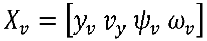
où yv est la position latérale du véhicule, vy la vitesse latérale du véhicule, Ψv l'angle de lacet et ωv la vitesse angulaire en lacet du véhicule. - Les matrices A, B et C sont décrites ci-après :


- où Cf et Cr correspondent à la raideur en virage respectivement au niveau des roues avant et arrière, vx est la vitesse du véhicule, m est la masse du véhicule, Iz est le moment d'inertie autour de l'axe vertical Z, et a et b sont les distances du centre de gravité du véhicule par rapport aux roues avant et arrière respectivement.
- Ce modèle dynamique propre au véhicule peut être connecté à un modèle descriptif du comportement des pneumatiques élaboré sur la base du modèle proposé par PACEJKA ou autre, pour inclure les limites de stabilité.
- La sortie du modèle 16 est connectée à un module 17 de détermination des états futurs du véhicule dans lequel sont calculées les positions futures du véhicule. Plus précisément, ce module 17 utilise la vitesse courante du véhicule, la position et l'orientation du véhicule, l'empattement et l'angle du volant de direction pour calculer la première itération. Ensuite, pour les états futurs, il fait évoluer le modèle de prédiction 16, en tenant compte de la réponse en boucle fermée d'un régulateur 18 de prédiction du véhicule, qui fournit la même réponse que les régulateurs mis en oeuvre dans les dispositifs de commande 12 et 13 du mouvement longitudinal et latéral du véhicule. Ainsi, les positions futures du véhicule sont estimées à l'aide de la même stratégie de contrôle que celle qui sera appliquée ultérieurement par les dispositifs de commande du mouvement longitudinal et latéral du véhicule auxdites positions.
- Ainsi, les valeurs d'entrée sont les ordres de commande prédits fournis par le régulateur 18, recueillis au début de l'itération en cours, et les valeurs d'état sont les composantes du vecteur d'état mis à jour Xv caractérisant l'état du système à l'itération précédente.
- La sortie du module 17 de détermination des états futurs du véhicule est donc fournie en premier lieu au régulateur 18 de prédiction du véhicule, qui comme indiqué précédemment, est équivalent aux dispositifs de commande12 et 13 du mouvement longitudinal et latéral du véhicule. La principale différence est que la sortie du régulateur de prédiction est également utilisée pour alimenter le modèle de prédiction 16, de façon à permettre de couvrir avec la prédiction les états futurs du véhicule sur l'ensemble de l'horizon électronique.
- La sortie du module 17 de détermination des états futurs du véhicule est également fournie à un module 19 de détermination de la violation de valeurs limites de roulage du véhicule. Ce module 19 inclut toutes les limites physiques provenant soit des actionneurs du véhicule, soit de la dynamique du véhicule lui-même. Il prend en compte l'angle maximal du volant de direction, la vitesse maximale d'angle du volant, la capacité de freinage maximale et la capacité d'accélération maximale. Il surveille tous les états futurs du véhicule par rapport à ces valeurs maximales et est adapté pour lever un drapeau indicateur lorsqu'un de ces états futurs dépasse les limites du véhicule.
- Le module 19 de détermination de la violation des limites de roulage du véhicule est connecté au module 15 de gestion des systèmes d'assistance à la conduite du véhicule. Ce dernier reçoit donc les sorties courantes des dispositifs de commande 12 et 13 et les sorties du régulateur de prédiction avec les indicateurs de violation. Il permet de modifier le comportement dynamique du véhicule en réagissant à l'avance en fonction des états futurs pour lesquels un indicateur de violation des limites de roulage du véhicule a été levé.
- L'exemple suivant illustre les principes qui viennent d'être décrit. La
figure 2 illustre en coordonnées X et Y, un exemple de trajectoire spécifique dans lequel une courbe prononcée C est réalisée. L'ensemble de la trajectoire est réalisée par un véhicule équipé d'un dispositif de commande 1 du mouvement du véhicule comme décrit précédemment en référence à lafigure 1 . Lesfigures 3A et 3B montrent plus précisément le moment exact où le modèle de prédiction du véhicule détecte des signaux de commande des actionneurs ou des états futurs du véhicule qui sont hors d'une plage contrôlable, c'est-à-dire qui atteignent ou dépassent une valeur limite de roulage du véhicule. Lafigure 3A représente la partie de trajectoire au niveau de la courbe prononcée C de lafigure 2 , tandis que lafigure 3B est une vue de détail de l'entrée dans la courbe prononcée C. Sur lafigure 3A sont représentés la trajectoire T à suivre par le véhicule, les états réels du véhicule st_real tels que déterminés par les capteurs embarqués, et les états futurs ou prédits du véhicule st_predicted fournis par le modèle de prédiction 16. Le véhicule suivra donc la trajectoire définie par l'ensemble des états réels du véhicule st_real, mais le modèle de prédiction est capable de détecter en avance, par exemple 800 ms avant, les états futurs du véhicule qui sont hors de la plage contrôlable, qui sont représentés par l'extrémité de la ligne st_predicted. - La
figure 4 représente l'erreur latérale en mètres du véhicule par rapport à la trajectoire à suivre, pendant toute la durée du parcours de lafigure 2 . La courbe ε_real représente l'erreur latérale des états réels du véhicule par rapport à la trajectoire à suivre et la courbe ε_predicted représente l'erreur latérale des états prédits du véhicule 800 ms avant par rapport à la trajectoire à suivre. Autour de la douzième seconde, des erreurs latérales de plus de 1 mètre apparaissent, signifiant que le véhicule sort de la plage contrôlable. - La
figure 5 présente le comportement de l'angle de braquage du volant α_real résultant de l'état réel du véhicule et de l'angle prédit α_predicted, en fonction du temps, ainsi que la valeur maximale α_max de l'angle de braquage du volant fournie par le système de direction assistée électrique, fixée à environ 65°. Suivant cet exemple, grâce à la prédiction, le véhicule peut détecter les états d'angle de braquage du volant qui atteignent la valeur maximale contrôlable avant qu'ils ne se produisent et prendre des décisions en conséquence. Lafigure 5 illustre l'avance temporelle des états prédits du véhicule qui, plus tard, correspondront aux états réels du véhicule. Ainsi, le modèle de prédiction permet de déterminer à l'avance les états futurs du véhicule correspondant à des situations potentiellement dangereuses où l'angle de braquage atteint la valeur maximale. - La
figure 6 illustre la sortie correspondante du module de détermination de la violation des limites de roulage du véhicule. Ainsi, la levée de l'indicateur de violation Id_predicted montre le moment où le module de détermination de la violation des limites de roulage du véhicule détecte que l'état futur du véhicule en ce qui concerne l'angle de braquage du volant viole la valeur limite maximale autorisée. Une telle alerte peut être émise pour une ou plusieurs variables d'état du véhicule prédites hors de sa plage contrôlable. Dans l'exemple présenté ici, la levée de l'indicateur Id_predicted permet d'informer le module de gestion 15 des systèmes d'assistance à la conduite s'agissant de l'évolution future de l'angle de braquage, environ 0,8 seconde avant que l'état réel ne se produise. Le module de gestion 15 des systèmes d'assistance à la conduite du véhicule est alors à même d'agir et de prévenir cette situation à l'avance, en commandant une action correctrice anticipative visant à empêcher que l'angle de braquage ne viole la valeur limite maximale autorisée. Une telle action correctrice anticipative peut par exemple consister en une action légère de freinage et/ou de direction. Ainsi, l'invention permet d'augmenter la sécurité du véhicule en anticipant les états futurs du véhicule où ses limites de stabilité pourraient être dépassées, en adoptant à l'avance des stratégies de sécurité appropriées.
Claims (6)
- Dispositif de commande (1) du mouvement d'un véhicule automobile sur une route, comprenant un module de gestion (15) d'au moins un système d'assistance à la conduite, notamment de type ESP, un dispositif embarqué (10) de détection de marquage au sol des voies de circulation, apte à fournir des premières informations relatives au tracé routier en fonction du marquage détecté, un ensemble de capteurs de mesure embarqués (11) aptes à fournir des deuxièmes informations relatives au comportement dynamique du véhicule, un dispositif de commande (12) du mouvement longitudinal du véhicule et un dispositif de commande (13) du mouvement latéral du véhicule, aptes à générer à partir des premières et deuxièmes informations des ordres de commande du mouvement longitudinal et du mouvement latéral à destination d'actionneurs (14) de contrôle longitudinal et latéral du système de direction du véhicule, comprenant un modèle de prédiction (16) du comportement dynamique du véhicule alimenté par les premières et deuxièmes informations, apte à déterminer un ensemble d'états futurs du véhicule correspondant à des positions futures du véhicule sur une pluralité d'itérations définissant une portion de route à venir, ledit modèle de prédiction étant connecté à un module (19) de détermination de la violation de valeurs limites de roulage du véhicule, apte à déterminer, pour chaque état futur déterminé, si l'une au moins de variables d'état définissant ledit état futur du véhicule atteint ou dépasse une des valeurs limites de roulage du véhicule, et à déduire une situation de risque à venir du véhicule pour au moins un des états futurs du véhicule, caractérisé en ce que le module (19) de détermination de la violation des valeurs limites de roulage du véhicule inclut parmi paramètres définissant une des valeurs limites de roulage du véhicule, des paramètres physiques relatifs auxdits actionneurs et/ou à la dynamique du véhicule, lesdits paramètres comprenant au moins une valeur maximale d'angle de braquage (α_max), une valeur maximale de vitesse d'angle du volant, une valeur représentative d'une capacité de freinage maximale et une valeur représentative d'une capacité d'accélération maximale du véhicule.
- Dispositif selon la revendication 1, caractérisé en ce que le modèle de prédiction (16) du comportement dynamique du véhicule reçoit en entrée des ordres de commande prédits aux actionneurs du véhicule délivrés par un régulateur (18) équivalent aux dispositifs de commande (12, 13) du mouvement longitudinal et du mouvement latéral du véhicule, des variables d'état de l'état futur du véhicule déterminé lors d'une itération en cours, ainsi que ses états courants, qui sont la position latérale du véhicule, la vitesse latérale du véhicule, l'angle de lacet et la vitesse angulaire en lacet du véhicule.
- Dispositif selon la revendication 1 ou 2, caractérisé en ce que ledit module de détermination de la violation des limites de roulage du véhicule est adapté pour comparer les états futurs déterminés du véhicule par rapport aux valeurs de limite de roulage du véhicule et pour générer un signal d'alerte (ld_predicted) dès qu'une au moins des variables d'état (α_predicted) définissant ces états futurs atteint la valeur de limite de roulage correspondante (a_max).
- Dispositif selon la revendication 3, caractérisé en ce que le module (15) de gestion du système d'assistance à la conduite est adapté pour recevoir ledit signal d'alerte généré et, en cas de réception dudit signal d'alerte, pour commander une action correctrice anticipative de ladite variable d'état.
- Dispositif selon la revendication 4, caractérisé en ce que ladite action correctrice anticipative comprend une action de freinage et/ou de direction.
- Véhicule automobile caractérisé en ce qu'il comprend un dispositif de commande selon l'une quelconque des revendications précédentes.
Applications Claiming Priority (2)
| Application Number | Priority Date | Filing Date | Title |
|---|---|---|---|
| FR1909681A FR3100200B1 (fr) | 2019-09-03 | 2019-09-03 | Dispositif de commande prédictif du mouvement d’un véhicule automobile |
| PCT/EP2020/074644 WO2021043925A1 (fr) | 2019-09-03 | 2020-09-03 | Dispositif de commande prédictif du mouvement d'un véhicule automobile |
Publications (2)
| Publication Number | Publication Date |
|---|---|
| EP4025468A1 EP4025468A1 (fr) | 2022-07-13 |
| EP4025468B1 true EP4025468B1 (fr) | 2024-11-06 |
Family
ID=68425121
Family Applications (1)
| Application Number | Title | Priority Date | Filing Date |
|---|---|---|---|
| EP20764400.6A Active EP4025468B1 (fr) | 2019-09-03 | 2020-09-03 | Dispositif de commande prédictif du mouvement d'un véhicule automobile |
Country Status (7)
| Country | Link |
|---|---|
| US (1) | US12134393B2 (fr) |
| EP (1) | EP4025468B1 (fr) |
| JP (1) | JP7546657B2 (fr) |
| KR (1) | KR20220053024A (fr) |
| CN (1) | CN114364590B (fr) |
| FR (1) | FR3100200B1 (fr) |
| WO (1) | WO2021043925A1 (fr) |
Families Citing this family (10)
| Publication number | Priority date | Publication date | Assignee | Title |
|---|---|---|---|---|
| US11359919B2 (en) * | 2019-10-04 | 2022-06-14 | Aptiv Technologies Limited | Calculating vehicle states of a vehicle system for lane centering |
| US12181873B2 (en) | 2021-06-30 | 2024-12-31 | Waymo Llc | Mass distribution-informed optimization for autonomous driving systems |
| US12195046B2 (en) * | 2021-06-30 | 2025-01-14 | Waymo Llc | Handling maneuver limits for autonomous driving systems |
| US20230227032A1 (en) * | 2022-01-20 | 2023-07-20 | Motional Ad Llc | Vehicle Dynamics Classification for Collision and Loss of Control Detection |
| CN114926802B (zh) * | 2022-06-24 | 2024-06-28 | 重庆长安汽车股份有限公司 | 基于双层lstm网络的车辆轨迹预测方法 |
| WO2024008307A1 (fr) * | 2022-07-08 | 2024-01-11 | Volvo Truck Corporation | Protection de sous-virage dans un véhicule |
| EP4626761A1 (fr) * | 2022-12-01 | 2025-10-08 | Volvo Truck Corporation | Système informatique et procédé mis en oeuvre par ordinateur pour la commande d'un véhicule |
| DE102023200790A1 (de) * | 2023-02-01 | 2024-08-01 | Robert Bosch Gesellschaft mit beschränkter Haftung | Verfahren zur Berechnung einer vorausliegenden Fahrzeugbahnkurve, Verfahren zur Steuerung einer Fahrzeugfunktion und Fahrzeug |
| US12415512B2 (en) | 2023-02-24 | 2025-09-16 | Steering Solutions Ip Holding Corporation | Vehicle lateral compensation for path deviation due to environmental forces |
| FR3148762A1 (fr) * | 2023-05-19 | 2024-11-22 | Renault | Procédé de contrôle d’une trajectoire d’un véhicule automobile le long d’une voie de circulation, |
Family Cites Families (25)
| Publication number | Priority date | Publication date | Assignee | Title |
|---|---|---|---|---|
| DE10018556A1 (de) * | 2000-04-14 | 2001-10-18 | Bosch Gmbh Robert | Verfahren zur Regelung der Geschwindigkeit eines Fahrzeugs |
| KR100851120B1 (ko) | 2006-12-13 | 2008-08-08 | 현대자동차주식회사 | 이에스피 통합형 차선 유지 지원장치 및 그 제어 방법 |
| US8380473B2 (en) * | 2009-06-13 | 2013-02-19 | Eric T. Falangas | Method of modeling dynamic characteristics of a flight vehicle |
| DE102013020558B4 (de) * | 2013-12-09 | 2025-04-30 | Audi Ag | Verfahren zur Fahrwerksregelung und Fahrwerksregelsystem |
| US20150203215A1 (en) * | 2014-01-17 | 2015-07-23 | Eric T. Falangas | Early performance evaluation of conceptual flight and space vehicles |
| CN104859650B (zh) * | 2015-05-28 | 2017-04-05 | 吉林大学 | 一种多时间尺度的车辆横摆稳定性滚动优化控制方法 |
| EP3118703B1 (fr) * | 2015-07-13 | 2018-05-23 | Volvo Car Corporation | Dispositif d'arrêt de sécurité et procédé d'arrêt de sécurité d'un véhicule autonome |
| JP6579699B2 (ja) | 2015-07-29 | 2019-09-25 | 株式会社Subaru | 車両の走行制御装置 |
| US9507346B1 (en) * | 2015-11-04 | 2016-11-29 | Zoox, Inc. | Teleoperation system and method for trajectory modification of autonomous vehicles |
| US10012984B2 (en) * | 2015-12-14 | 2018-07-03 | Mitsubishi Electric Research Laboratories, Inc. | System and method for controlling autonomous vehicles |
| CN105711588B (zh) * | 2016-01-20 | 2018-05-11 | 奇瑞汽车股份有限公司 | 一种车道保持辅助系统和车道保持辅助方法 |
| US9731755B1 (en) * | 2016-02-16 | 2017-08-15 | GM Global Technology Operations LLC | Preview lateral control for automated driving |
| US9849878B2 (en) * | 2016-02-26 | 2017-12-26 | GM Global Technology Operations LLC | System and method for providing a corrected lane following path through a curve for trailering vehicles |
| US10967877B2 (en) * | 2016-04-15 | 2021-04-06 | Honda Motor Co., Ltd. | Vehicle control system, vehicle control method, and vehicle control program |
| DE102017108692B4 (de) | 2016-04-25 | 2024-09-26 | Steering Solutions Ip Holding Corporation | Steuerung einer elektrischen Servolenkung unter Verwendung von Systemzustandsvorhersagen |
| US9915948B2 (en) * | 2016-07-14 | 2018-03-13 | Mitsubishi Electric Research Laboratories, Inc. | System and method for controlling motion of vehicle |
| US10345815B2 (en) * | 2016-09-14 | 2019-07-09 | Qualcomm Incorporated | Motion planning and intention prediction for autonomous driving in highway scenarios via graphical model-based factorization |
| US10019008B2 (en) | 2016-09-28 | 2018-07-10 | Baidu Usa Llc | Sideslip compensated control method for autonomous vehicles |
| US10012993B1 (en) * | 2016-12-09 | 2018-07-03 | Zendrive, Inc. | Method and system for risk modeling in autonomous vehicles |
| DE102017205508A1 (de) * | 2017-03-31 | 2018-10-04 | Robert Bosch Gmbh | Verfahren zur automatischen Bewegungssteuerung eines Fahrzeugs |
| MY188554A (en) | 2017-08-24 | 2021-12-22 | Nissan Motor | Method and device for controlling travel of drive-assisted vehicle |
| CN111213193B (zh) * | 2017-10-11 | 2022-02-25 | 本田技研工业株式会社 | 车辆控制装置 |
| JP2019156192A (ja) * | 2018-03-14 | 2019-09-19 | 本田技研工業株式会社 | 車両制御装置 |
| US10663963B2 (en) * | 2018-08-03 | 2020-05-26 | Here Global B.V. | Method and apparatus for visualizing future events for passengers of autonomous vehicles |
| US11155258B2 (en) * | 2019-03-25 | 2021-10-26 | GM Global Technology Operations LLC | System and method for radar cross traffic tracking and maneuver risk estimation |
-
2019
- 2019-09-03 FR FR1909681A patent/FR3100200B1/fr active Active
-
2020
- 2020-09-03 US US17/639,149 patent/US12134393B2/en active Active
- 2020-09-03 EP EP20764400.6A patent/EP4025468B1/fr active Active
- 2020-09-03 WO PCT/EP2020/074644 patent/WO2021043925A1/fr not_active Ceased
- 2020-09-03 CN CN202080061943.9A patent/CN114364590B/zh active Active
- 2020-09-03 KR KR1020227011067A patent/KR20220053024A/ko active Pending
- 2020-09-03 JP JP2022512827A patent/JP7546657B2/ja active Active
Also Published As
| Publication number | Publication date |
|---|---|
| JP2022547414A (ja) | 2022-11-14 |
| WO2021043925A1 (fr) | 2021-03-11 |
| JP7546657B2 (ja) | 2024-09-06 |
| FR3100200A1 (fr) | 2021-03-05 |
| FR3100200B1 (fr) | 2022-02-25 |
| US20220324466A1 (en) | 2022-10-13 |
| CN114364590A (zh) | 2022-04-15 |
| EP4025468A1 (fr) | 2022-07-13 |
| US12134393B2 (en) | 2024-11-05 |
| CN114364590B (zh) | 2026-01-09 |
| KR20220053024A (ko) | 2022-04-28 |
Similar Documents
| Publication | Publication Date | Title |
|---|---|---|
| EP4025468B1 (fr) | Dispositif de commande prédictif du mouvement d'un véhicule automobile | |
| EP3627270B1 (fr) | Dispositif électronique de détermination d'une trajectoire d'arrêt d'urgence d'un véhicule autonome, véhicule et procédé associés | |
| EP3938260B1 (fr) | Procédé d'élaboration d'une consigne de pilotage mixte d'un système de braquage de roues et d'un système de freinage différentiel d'un véhicule automobile | |
| EP4037947B1 (fr) | Dispositif de contrôle d'un véhicule automobile à conduite autonome | |
| US12459497B2 (en) | Systems and methods for updating the parameters of a model predictive controller with learned controls parameters generated using simulations and machine learning | |
| US20250360931A1 (en) | Systems and methods for updating the parameters of a model predictive controller with learned external parameters generated using simulations and machine learning | |
| EP3344505B1 (fr) | Dispositif et procédé de commande d'un système d'aide a la conduite pour la correction de trajectoire d'un véhicule automobile | |
| EP4037948B1 (fr) | Dispositif de contrôle de l'angle de braquage d'un véhicule automobile à conduite autonome | |
| EP3994042B1 (fr) | Procédé de détermination d'une trajectoire d'évitement d'un véhicule automobile | |
| EP3947076B1 (fr) | Module anticipateur, dispositif de contrôle en temps réel de trajectoire et procédé associés | |
| US20240067220A1 (en) | Tow-vehicle driving methods and systems for automated driving | |
| WO2022083970A1 (fr) | Procédé de régulation de la position latérale d'un véhicule sur une voie de circulation | |
| WO2000036435A1 (fr) | Procede de regulation de vitesse pour vehicule automobile | |
| EP4157689B1 (fr) | Procede d'aide a la conduite avec cible virtuelle de regulation de l'acc | |
| EP4263312B1 (fr) | Dispositif et procédé de contrôle de véhicule dépendant de la trajectoire | |
| EP0927677A1 (fr) | Système de commande d'une direction intelligente de véhicule automobile | |
| FR3072634A1 (fr) | Procede d'assistance a la conduite d'un vehicule automobile | |
| FR3086075A1 (fr) | Systeme electronique de supervision d'un vehicule autonome, procede et programme d'ordinateur associes | |
| EP3877821B1 (fr) | Procédé de détermination d'une trajectoire d'un véhicule autonome | |
| EP3901005B1 (fr) | Système et procédé de pilotage d'un système de contrôle latéral d'un véhicule automobile en fonction d'une modélisation d'un système de braquage des roues | |
| FR2912981A1 (fr) | Procede de pilotage automatique de vehicule automobile comprenant un systeme acc | |
| FR3143812A1 (fr) | Système analytique d’une manœuvre de stationnement manuelle d’un véhicule | |
| FR3105960A1 (fr) | Méthodes et systèmes d’observation d’une fonction de régulation de la vitesse | |
| EP4263311B1 (fr) | Méthode de contrôle pour contrôler le déplacement d'un véhicule automobile autonome | |
| FR3092914A1 (fr) | Procédé de détermination de la trajectoire d'un véhicule comprenant quatre roues directrices |
Legal Events
| Date | Code | Title | Description |
|---|---|---|---|
| STAA | Information on the status of an ep patent application or granted ep patent |
Free format text: STATUS: UNKNOWN |
|
| STAA | Information on the status of an ep patent application or granted ep patent |
Free format text: STATUS: THE INTERNATIONAL PUBLICATION HAS BEEN MADE |
|
| PUAI | Public reference made under article 153(3) epc to a published international application that has entered the european phase |
Free format text: ORIGINAL CODE: 0009012 |
|
| STAA | Information on the status of an ep patent application or granted ep patent |
Free format text: STATUS: REQUEST FOR EXAMINATION WAS MADE |
|
| 17P | Request for examination filed |
Effective date: 20220211 |
|
| AK | Designated contracting states |
Kind code of ref document: A1 Designated state(s): AL AT BE BG CH CY CZ DE DK EE ES FI FR GB GR HR HU IE IS IT LI LT LU LV MC MK MT NL NO PL PT RO RS SE SI SK SM TR |
|
| DAV | Request for validation of the european patent (deleted) | ||
| DAX | Request for extension of the european patent (deleted) | ||
| P01 | Opt-out of the competence of the unified patent court (upc) registered |
Effective date: 20230608 |
|
| RAP1 | Party data changed (applicant data changed or rights of an application transferred) |
Owner name: AMPERE SAS |
|
| GRAP | Despatch of communication of intention to grant a patent |
Free format text: ORIGINAL CODE: EPIDOSNIGR1 |
|
| STAA | Information on the status of an ep patent application or granted ep patent |
Free format text: STATUS: GRANT OF PATENT IS INTENDED |
|
| INTG | Intention to grant announced |
Effective date: 20240528 |
|
| GRAS | Grant fee paid |
Free format text: ORIGINAL CODE: EPIDOSNIGR3 |
|
| GRAA | (expected) grant |
Free format text: ORIGINAL CODE: 0009210 |
|
| STAA | Information on the status of an ep patent application or granted ep patent |
Free format text: STATUS: THE PATENT HAS BEEN GRANTED |
|
| AK | Designated contracting states |
Kind code of ref document: B1 Designated state(s): AL AT BE BG CH CY CZ DE DK EE ES FI FR GB GR HR HU IE IS IT LI LT LU LV MC MK MT NL NO PL PT RO RS SE SI SK SM TR |
|
| REG | Reference to a national code |
Ref country code: GB Ref legal event code: FG4D Free format text: NOT ENGLISH |
|
| REG | Reference to a national code |
Ref country code: CH Ref legal event code: EP |
|
| REG | Reference to a national code |
Ref country code: DE Ref legal event code: R096 Ref document number: 602020040876 Country of ref document: DE |
|
| REG | Reference to a national code |
Ref country code: IE Ref legal event code: FG4D Free format text: LANGUAGE OF EP DOCUMENT: FRENCH |
|
| REG | Reference to a national code |
Ref country code: LT Ref legal event code: MG9D |
|
| REG | Reference to a national code |
Ref country code: NL Ref legal event code: MP Effective date: 20241106 |
|
| PG25 | Lapsed in a contracting state [announced via postgrant information from national office to epo] |
Ref country code: PT Free format text: LAPSE BECAUSE OF FAILURE TO SUBMIT A TRANSLATION OF THE DESCRIPTION OR TO PAY THE FEE WITHIN THE PRESCRIBED TIME-LIMIT Effective date: 20250306 Ref country code: HR Free format text: LAPSE BECAUSE OF FAILURE TO SUBMIT A TRANSLATION OF THE DESCRIPTION OR TO PAY THE FEE WITHIN THE PRESCRIBED TIME-LIMIT Effective date: 20241106 Ref country code: IS Free format text: LAPSE BECAUSE OF FAILURE TO SUBMIT A TRANSLATION OF THE DESCRIPTION OR TO PAY THE FEE WITHIN THE PRESCRIBED TIME-LIMIT Effective date: 20250306 |
|
| PG25 | Lapsed in a contracting state [announced via postgrant information from national office to epo] |
Ref country code: FI Free format text: LAPSE BECAUSE OF FAILURE TO SUBMIT A TRANSLATION OF THE DESCRIPTION OR TO PAY THE FEE WITHIN THE PRESCRIBED TIME-LIMIT Effective date: 20241106 Ref country code: NL Free format text: LAPSE BECAUSE OF FAILURE TO SUBMIT A TRANSLATION OF THE DESCRIPTION OR TO PAY THE FEE WITHIN THE PRESCRIBED TIME-LIMIT Effective date: 20241106 |
|
| REG | Reference to a national code |
Ref country code: AT Ref legal event code: MK05 Ref document number: 1739062 Country of ref document: AT Kind code of ref document: T Effective date: 20241106 |
|
| PG25 | Lapsed in a contracting state [announced via postgrant information from national office to epo] |
Ref country code: BG Free format text: LAPSE BECAUSE OF FAILURE TO SUBMIT A TRANSLATION OF THE DESCRIPTION OR TO PAY THE FEE WITHIN THE PRESCRIBED TIME-LIMIT Effective date: 20241106 |
|
| PG25 | Lapsed in a contracting state [announced via postgrant information from national office to epo] |
Ref country code: ES Free format text: LAPSE BECAUSE OF FAILURE TO SUBMIT A TRANSLATION OF THE DESCRIPTION OR TO PAY THE FEE WITHIN THE PRESCRIBED TIME-LIMIT Effective date: 20241106 |
|
| PG25 | Lapsed in a contracting state [announced via postgrant information from national office to epo] |
Ref country code: NO Free format text: LAPSE BECAUSE OF FAILURE TO SUBMIT A TRANSLATION OF THE DESCRIPTION OR TO PAY THE FEE WITHIN THE PRESCRIBED TIME-LIMIT Effective date: 20250206 |
|
| PG25 | Lapsed in a contracting state [announced via postgrant information from national office to epo] |
Ref country code: GR Free format text: LAPSE BECAUSE OF FAILURE TO SUBMIT A TRANSLATION OF THE DESCRIPTION OR TO PAY THE FEE WITHIN THE PRESCRIBED TIME-LIMIT Effective date: 20250207 Ref country code: LV Free format text: LAPSE BECAUSE OF FAILURE TO SUBMIT A TRANSLATION OF THE DESCRIPTION OR TO PAY THE FEE WITHIN THE PRESCRIBED TIME-LIMIT Effective date: 20241106 Ref country code: AT Free format text: LAPSE BECAUSE OF FAILURE TO SUBMIT A TRANSLATION OF THE DESCRIPTION OR TO PAY THE FEE WITHIN THE PRESCRIBED TIME-LIMIT Effective date: 20241106 |
|
| PG25 | Lapsed in a contracting state [announced via postgrant information from national office to epo] |
Ref country code: PL Free format text: LAPSE BECAUSE OF FAILURE TO SUBMIT A TRANSLATION OF THE DESCRIPTION OR TO PAY THE FEE WITHIN THE PRESCRIBED TIME-LIMIT Effective date: 20241106 |
|
| PG25 | Lapsed in a contracting state [announced via postgrant information from national office to epo] |
Ref country code: RS Free format text: LAPSE BECAUSE OF FAILURE TO SUBMIT A TRANSLATION OF THE DESCRIPTION OR TO PAY THE FEE WITHIN THE PRESCRIBED TIME-LIMIT Effective date: 20250206 |
|
| PG25 | Lapsed in a contracting state [announced via postgrant information from national office to epo] |
Ref country code: SM Free format text: LAPSE BECAUSE OF FAILURE TO SUBMIT A TRANSLATION OF THE DESCRIPTION OR TO PAY THE FEE WITHIN THE PRESCRIBED TIME-LIMIT Effective date: 20241106 |
|
| PG25 | Lapsed in a contracting state [announced via postgrant information from national office to epo] |
Ref country code: DK Free format text: LAPSE BECAUSE OF FAILURE TO SUBMIT A TRANSLATION OF THE DESCRIPTION OR TO PAY THE FEE WITHIN THE PRESCRIBED TIME-LIMIT Effective date: 20241106 |
|
| PG25 | Lapsed in a contracting state [announced via postgrant information from national office to epo] |
Ref country code: EE Free format text: LAPSE BECAUSE OF FAILURE TO SUBMIT A TRANSLATION OF THE DESCRIPTION OR TO PAY THE FEE WITHIN THE PRESCRIBED TIME-LIMIT Effective date: 20241106 |
|
| PG25 | Lapsed in a contracting state [announced via postgrant information from national office to epo] |
Ref country code: RO Free format text: LAPSE BECAUSE OF FAILURE TO SUBMIT A TRANSLATION OF THE DESCRIPTION OR TO PAY THE FEE WITHIN THE PRESCRIBED TIME-LIMIT Effective date: 20241106 |
|
| PG25 | Lapsed in a contracting state [announced via postgrant information from national office to epo] |
Ref country code: SK Free format text: LAPSE BECAUSE OF FAILURE TO SUBMIT A TRANSLATION OF THE DESCRIPTION OR TO PAY THE FEE WITHIN THE PRESCRIBED TIME-LIMIT Effective date: 20241106 |
|
| PG25 | Lapsed in a contracting state [announced via postgrant information from national office to epo] |
Ref country code: CZ Free format text: LAPSE BECAUSE OF FAILURE TO SUBMIT A TRANSLATION OF THE DESCRIPTION OR TO PAY THE FEE WITHIN THE PRESCRIBED TIME-LIMIT Effective date: 20241106 |
|
| PG25 | Lapsed in a contracting state [announced via postgrant information from national office to epo] |
Ref country code: IT Free format text: LAPSE BECAUSE OF FAILURE TO SUBMIT A TRANSLATION OF THE DESCRIPTION OR TO PAY THE FEE WITHIN THE PRESCRIBED TIME-LIMIT Effective date: 20241106 |
|
| REG | Reference to a national code |
Ref country code: DE Ref legal event code: R097 Ref document number: 602020040876 Country of ref document: DE |
|
| PG25 | Lapsed in a contracting state [announced via postgrant information from national office to epo] |
Ref country code: SE Free format text: LAPSE BECAUSE OF FAILURE TO SUBMIT A TRANSLATION OF THE DESCRIPTION OR TO PAY THE FEE WITHIN THE PRESCRIBED TIME-LIMIT Effective date: 20241106 |
|
| PLBE | No opposition filed within time limit |
Free format text: ORIGINAL CODE: 0009261 |
|
| STAA | Information on the status of an ep patent application or granted ep patent |
Free format text: STATUS: NO OPPOSITION FILED WITHIN TIME LIMIT |
|
| PGFP | Annual fee paid to national office [announced via postgrant information from national office to epo] |
Ref country code: DE Payment date: 20250919 Year of fee payment: 6 |
|
| 26N | No opposition filed |
Effective date: 20250807 |
|
| PGFP | Annual fee paid to national office [announced via postgrant information from national office to epo] |
Ref country code: GB Payment date: 20250919 Year of fee payment: 6 |
|
| PGFP | Annual fee paid to national office [announced via postgrant information from national office to epo] |
Ref country code: FR Payment date: 20250922 Year of fee payment: 6 |