EP4025744B1 - Plancher en béton, éléments de plancher en béton et procédés de fabrication d'un plancher en béton et d'un élément de plancher en béton - Google Patents
Plancher en béton, éléments de plancher en béton et procédés de fabrication d'un plancher en béton et d'un élément de plancher en béton Download PDFInfo
- Publication number
- EP4025744B1 EP4025744B1 EP19766004.6A EP19766004A EP4025744B1 EP 4025744 B1 EP4025744 B1 EP 4025744B1 EP 19766004 A EP19766004 A EP 19766004A EP 4025744 B1 EP4025744 B1 EP 4025744B1
- Authority
- EP
- European Patent Office
- Prior art keywords
- frc
- extension
- concrete ceiling
- recess
- concrete
- Prior art date
- Legal status (The legal status is an assumption and is not a legal conclusion. Google has not performed a legal analysis and makes no representation as to the accuracy of the status listed.)
- Active
Links
Images


Classifications
-
- E—FIXED CONSTRUCTIONS
- E04—BUILDING
- E04B—GENERAL BUILDING CONSTRUCTIONS; WALLS, e.g. PARTITIONS; ROOFS; FLOORS; CEILINGS; INSULATION OR OTHER PROTECTION OF BUILDINGS
- E04B1/00—Constructions in general; Structures which are not restricted either to walls, e.g. partitions, or floors or ceilings or roofs
- E04B1/02—Structures consisting primarily of load-supporting, block-shaped, or slab-shaped elements
- E04B1/04—Structures consisting primarily of load-supporting, block-shaped, or slab-shaped elements the elements consisting of concrete, e.g. reinforced concrete, or other stone-like material
- E04B1/06—Structures consisting primarily of load-supporting, block-shaped, or slab-shaped elements the elements consisting of concrete, e.g. reinforced concrete, or other stone-like material the elements being prestressed
-
- E—FIXED CONSTRUCTIONS
- E04—BUILDING
- E04B—GENERAL BUILDING CONSTRUCTIONS; WALLS, e.g. PARTITIONS; ROOFS; FLOORS; CEILINGS; INSULATION OR OTHER PROTECTION OF BUILDINGS
- E04B5/00—Floors; Floor construction with regard to insulation; Connections specially adapted therefor
- E04B5/02—Load-carrying floor structures formed substantially of prefabricated units
- E04B5/04—Load-carrying floor structures formed substantially of prefabricated units with beams or slabs of concrete or other stone-like material, e.g. asbestos cement
-
- E—FIXED CONSTRUCTIONS
- E04—BUILDING
- E04B—GENERAL BUILDING CONSTRUCTIONS; WALLS, e.g. PARTITIONS; ROOFS; FLOORS; CEILINGS; INSULATION OR OTHER PROTECTION OF BUILDINGS
- E04B5/00—Floors; Floor construction with regard to insulation; Connections specially adapted therefor
- E04B5/43—Floor structures of extraordinary design; Features relating to the elastic stability; Floor structures specially designed for resting on columns only, e.g. mushroom floors
-
- E—FIXED CONSTRUCTIONS
- E04—BUILDING
- E04B—GENERAL BUILDING CONSTRUCTIONS; WALLS, e.g. PARTITIONS; ROOFS; FLOORS; CEILINGS; INSULATION OR OTHER PROTECTION OF BUILDINGS
- E04B5/00—Floors; Floor construction with regard to insulation; Connections specially adapted therefor
- E04B5/48—Special adaptations of floors for incorporating ducts, e.g. for heating or ventilating
-
- E—FIXED CONSTRUCTIONS
- E04—BUILDING
- E04C—STRUCTURAL ELEMENTS; BUILDING MATERIALS
- E04C3/00—Structural elongated elements designed for load-supporting
- E04C3/02—Joists; Girders, trusses, or trusslike structures, e.g. prefabricated; Lintels; Transoms; Braces
- E04C3/20—Joists; Girders, trusses, or trusslike structures, e.g. prefabricated; Lintels; Transoms; Braces of concrete or other stone-like material, e.g. with reinforcements or tensioning members
- E04C3/26—Joists; Girders, trusses, or trusslike structures, e.g. prefabricated; Lintels; Transoms; Braces of concrete or other stone-like material, e.g. with reinforcements or tensioning members prestressed
-
- E—FIXED CONSTRUCTIONS
- E04—BUILDING
- E04C—STRUCTURAL ELEMENTS; BUILDING MATERIALS
- E04C5/00—Reinforcing elements, e.g. for concrete; Auxiliary elements therefor
- E04C5/07—Reinforcing elements of material other than metal, e.g. of glass, of plastics, or not exclusively made of metal
-
- Y—GENERAL TAGGING OF NEW TECHNOLOGICAL DEVELOPMENTS; GENERAL TAGGING OF CROSS-SECTIONAL TECHNOLOGIES SPANNING OVER SEVERAL SECTIONS OF THE IPC; TECHNICAL SUBJECTS COVERED BY FORMER USPC CROSS-REFERENCE ART COLLECTIONS [XRACs] AND DIGESTS
- Y02—TECHNOLOGIES OR APPLICATIONS FOR MITIGATION OR ADAPTATION AGAINST CLIMATE CHANGE
- Y02B—CLIMATE CHANGE MITIGATION TECHNOLOGIES RELATED TO BUILDINGS, e.g. HOUSING, HOUSE APPLIANCES OR RELATED END-USER APPLICATIONS
- Y02B30/00—Energy efficient heating, ventilation or air conditioning [HVAC]
Definitions
- the present invention relates, inter alia, to a concrete ceiling, concrete ceiling elements and methods for producing a concrete ceiling and for producing a concrete ceiling element.
- the classic reinforced concrete ceiling is widely used in building construction. Due to the steel reinforcements, it can absorb high tensile forces as well as high compressive forces and is therefore particularly stable.
- Such a reinforced concrete ceiling is usually constructed by first arranging formwork panels flat on the existing building walls and supporting them with the help of supports. Spacers are then placed on the level formed by the formwork panels, on which a first steel grid is then arranged. Usually another layer of spacers follows on the first steel grid, on which another steel grid is arranged. Pipes, such as pipes for the underfloor heating or cable ducts, must then be laid in the steel grid structure before everything can be poured with concrete to form the later reinforced concrete ceiling.
- this ceiling is particularly stable, but also requires a large amount of raw materials, particularly concrete, and has a high dead weight. Subsequent adjustments, such as laying new pipes are difficult and the initial production of such a reinforced concrete slab on site does not always run smoothly due to a certain dependence on the prevailing weather conditions. Frost, extreme heat or heavy rainfall can affect the setting process of the concrete and thus influence the quality of the reinforced concrete slab, which is why weather conditions must be taken into account when producing it.
- the US 3475529 A discloses a method for forming a prestressed concrete structure with voids extending through the concrete structure.
- the object of the present invention is to provide a concrete ceiling which overcomes at least one disadvantage of reinforced concrete ceilings known from the prior art.
- aspects of the invention relate to concrete ceiling elements for producing a concrete ceiling, methods for producing a concrete ceiling and concrete ceilings per se. Further aspects of the invention relate to the use of FRC concrete elements and the use of special connection techniques for FRC elements.
- Said concrete ceiling element comprises a flat base structure which comprises at least one FRC plate and has an upper side.
- the concrete ceiling element also comprises at least one FRC web.
- the FRC web is arranged on the upper side and connected to the basic structure in sections.
- FRC plates are described in the WO2014/040653 A1 FRC plates are prestressed with fibers made of carbon, glass, Kevlar, basalt, steel, natural fibers or the like, whose cross-sectional area is less than 5 mm 2 , and have a thickness of a few centimeters (e.g. 1 cm to 10 cm).
- the width and length are in the range of a few meters (1 m, 2 m, ..., 5 m etc.) up to 10 m or even 20 m to 40 m.
- the reinforcement of the plates can be based on different distances and arrangements of the fibers to each other.
- the fibers used have a very high tensile strength and preferably do not corrode, they can be used to produce particularly load-bearing, thin concrete slabs.
- the reinforcement cover of three to four centimeters required for conventional reinforced concrete slabs is no longer necessary.
- FRC slabs are therefore significantly thinner and have a lower weight - and this with the same load-bearing capacity.
- a special version of an FRC slab is the CPC slab.
- the letters "CPC" stand for "carbon prestressed concrete” and describe the concrete slabs reinforced with thin prestressed carbon strands, which can be used according to the invention and are particularly delicate and yet resilient.
- Typical FRC panels used for concrete ceiling elements are between 10 and 100 mm thick, in particular between 20 and 60 mm, e.g. 25 mm or 30 mm, in particular 40 mm in terms of fire protection, and have, for example, a 4-layer CFRP reinforcement.
- the FRC panels can have lengths and widths of several meters. For example, 1 m ⁇ 2 m, 2 m ⁇ 2 m, 2 mx 4 m up to 20 mx 40 m.
- a maximum width of 2.4 m is preferred, as this still allows problem-free road transport.
- a width of up to 3.5 m or even up to 6 m is also possible, although this may result in more difficult transport conditions.
- the length of the FRC panels is preferably determined by the floor area of the rooms to be spanned or the building dimensions and is typically in the range of approx. 4 m or 5 m up to 12 m or even 20 m.
- the underside and the top of an FRC panel are usually identical, so only the attachment of the FRC web or several FRC webs determines which side in the further course of the construction of the concrete ceiling acts as the upper side.
- the FRC webs are also made of FRC and are preferably cut from FRC plates.
- a web describes an elongated structure which can be attached to the base structure like a type of rib or lamella, but does not have to be connected to the base structure along its entire length.
- An FRC web preferably has a thickness of 2 cm to 10 cm, in particular 4 cm to 8 cm, such as 6 cm, which thickness extends constantly or in a varying manner over the entire length and width of the FRC web.
- the length of the webs is, for example, adapted to the length or width of the FRC slab and is therefore typically in the range of several meters, e.g. between 1 m and 20 m or even up to 40 m.
- the height of an FRC web or the supports of the FRC web varies, among other things depending on the length of the space to be spanned under the concrete ceiling element, and is usually in the range of one tenth to one thirtieth of the space to be spanned by the ceiling. In particular, it is the distance between two adjacent support points, which divided by 10 to 30 gives the height of the FRC webs.
- the height of the webs can also be higher for structural reasons, for example if cables have to be run at the height of the ceiling element or if adjoining rooms have significantly larger support distances and the ceiling element thickness is to be kept constant across the entire ceiling.
- FRC web height 8 cm to 24 cm or 20 cm to 60 cm. Since the maximum distance between two support points is decisive for the dimensioning of the FRC webs, these are manufactured with a height of 20 cm to 60 cm. If the FRC webs are used crosswise, it may be advisable to specify the same height for the transverse and longitudinal CPC webs.
- concrete ceiling element can be used to produce a concrete ceiling.
- this term is in no way intended to be restrictive.
- the FRC web has at least two supports which provide the section-wise connection to the base structure.
- this connection is preferably force-fitting and is made, for example, via one or more extensions per support. These extensions preferably not only border on the top of the basic structure, but also engage with the basic structure.
- Such a web is made up of areas, the supports, which are intended to come into at least partial contact with the basic structure, in particular by frictional engagement and with the help of extensions, and areas, the recesses, which are intended not to come into contact with the basic structure, and above all not by frictional engagement.
- These recesses in particular provide a free space or a passage.
- Webs with arched recesses, in particular with semi-circular recesses, are particularly stable and also uncomplicated to manufacture, but in principle other recess shapes can also be realized, such as oval, triangular, rectangular or other polygonal shapes.
- the height of the recess can be between approx. 1% and approx. 80% compared to the height of the FRC web or the supports of the FRC web already discussed.
- the height of the recess can be as little as 2 mm or as high as 16 cm. However, it is preferred that the recess is only large enough to leave a minimum material thickness of 4 cm to 20 cm between the supports, depending on the load and span of the intended ceiling.
- the opening length of the recess in the support area of the concrete ceiling elements is approximately 0.5 to twice the height of the webs and in particular at least 10 cm or even at least 20 cm or at least 30 cm. In the middle area of the span, the opening length of the recess can also be several times the height of the webs.
- recesses in an FRC web can have different sizes (applies to both opening length and opening height).
- webs with just one recess and two supports can be used, or webs with a large number of n recesses (e.g. 2, 3, 4, 5, 6, 7, 8, 9, 10, 11, 12, 13, 14, 15, 16, 17, 18, 19, 20, ...) and a large number of m supports, where the number of supports is e.g. n, n+1 or n-1.
- n recesses e.g. 2, 3, 4, 5, 6, 7, 8, 9, 10, 11, 12, 13, 14, 15, 16, 17, 18, 19, 20,
- m supports e.g. n, n+1 or n-1.
- the FRC webs are either aligned parallel to each other or at an angle of less than 180° and greater than 0°, in particular at an angle of 90°, i.e. orthogonal or perpendicular to each other. If the concrete ceiling element comprises more than two FRC webs, some of the FRC webs can be arranged parallel to each other while another part of the FRC webs is arranged at an angle of less than 180° and greater than 0°, in particular at an angle of 90°, to the first-mentioned part.
- Such an arrangement can be preferred over an equidistant arrangement in terms of statics and does not offer any disadvantages in terms of use.
- a non-equidistant arrangement can be the result. For example, if two FRC panels of 2.4 m width are connected to each other by two FRC webs at a distance of 1.6 m to each other and at a distance of 0.4 m from the edge of the FRC plate.
- a part of the FRC webs arranged parallel to one another is not arranged equidistantly from another part of the FRC webs arranged parallel to one another in such a way that at least one region of higher FRC web density is formed.
- a higher FRC web density i.e. more FRC webs per unit area of the top of the basic structure, ensures local reinforcement of the concrete ceiling element. This is advantageous, for example, for reinforcing the concrete ceiling element in those areas that are particularly stressed during the manufacturing process of the concrete ceiling due to the concrete ceiling element resting on or supporting the side walls of the building or ceiling supports.
- Such narrower spacing can be in the range of half to a quarter of the usual spacing, i.e. 5 cm or 10 cm to 75 cm or 150 cm, in particular 30 cm.
- At least two of the FRC webs are arranged at an angle of less than 180° and greater than 0°, in particular orthogonally, to each other, so that the at least two FRC webs intersect at an intersection point. At this intersection point, the at least two FRC webs are inserted into each other or onto each other.
- the plug connection enables the alignment of the FRC bars to be fixed to one another and also ensures the fastening, or at least contributes to the fastening, of the FRC bar that is plugged in or on top, provided that the other FRC bar is already connected to the base structure in another way. Furthermore, the plug connection can ensure that the FRC bars form a flat support surface on the top of the base structure, for example for parquet boards or the like that are to be attached later on.
- At least one of the two FRC webs may have a groove at the intersection point.
- the additional FRC web that is to be arranged at an angle to an existing FRC web can have a groove in order to be plugged onto the existing FRC web.
- the upper edge of the additional FRC web arranged later would then be higher up than that of the existing FRC web.
- At least two of the FRC webs each have an opposing groove at the intersection point.
- the groove of one FRC web must be at least as wide as the other FRC web, and vice versa.
- the grooves are usually designed a little more generously, thus allowing for a certain amount of play.
- the depth of the two grooves in total corresponds to at least the height of the FRC webs at the intersection, which have an identical height.
- the grooves that open upwards can be filled with a filler (e.g. mortar) to compensate for the gap inaccuracy, i.e. the play described above and the resulting empty space.
- a filler e.g. mortar
- an FRC web or a fragment of an FRC web composed of several fragments, arranged at an angle of less than 180° and greater than 0°, in particular orthogonally, between at least two other FRC webs and connected to them.
- connection of one FRC web or the fragment of such with the other two transverse FRC webs can be made, for example, using a binding agent such as mortar or adhesive. This can be used to at least partially fill the gaps between the ends of one FRC web or the FRC web fragment and the other two adjacent FRC webs.
- the fragment or the FRC web can be conically shaped and thus inserted or clamped between the other two FRC webs.
- a clamp connection can also be provided, for example, by driving a wedge or the like into the gap.
- At least three, in particular at least four, of the FRC webs are arranged relative to one another in such a way that they enclose a space which is at least partially filled with concrete.
- the concrete ceiling element can be reinforced in a targeted manner, for example at specific points, but also over a larger area.
- At least one of the FRC webs is solid and/or at least one of the FRC webs has a cavity.
- the individual design of the FRC webs offers the possibility of optimally adapting the concrete ceiling element to the stability requirements of the concrete ceiling built on top of it.
- all FRC webs are identically designed and solid.
- a part or the entire number of FRC webs can be designed with one or more cavities, e.g. in the form of a slot.
- Upper tensile reinforcements can then be inserted into these cavities.
- the cavities are filled with mortar or adhesive, for example.
- the use of upper tensile reinforcements using the cavities is particularly useful above ceiling supports or walls.
- Tensile elements such as a tension rod, or steel reinforcements or textile reinforcements (e.g.
- a cavity is, for example, 10 mm to 30 mm wide. For stronger, i.e. thicker, bars, it can also be wider, for example up to the bar width minus 20mm. A cavity is, for example, 40 mm to 100 mm or even up to 150 mm deep.
- the basic structure comprises at least two FRC plates arranged flat next to each other and adjacent to each other.
- the FRC panels and FRC webs can be advantageous to deliver separately and then produce precisely fitting concrete ceiling elements on site, the basic structure of which requires more than one FRC panel.
- the concrete ceiling is to cover an area of 8 m x 8 m, but only FRC panels with an area of 2 m x 8 m can be delivered to the construction site without special transport, a total of four concrete ceiling elements with four FRC panels each in the basic structure can be produced on site for this concrete ceiling. But even if concrete ceiling elements in a special size are required, these can simply be put together from several FRC panels manufactured in a standard size and even cut to size.
- the FRC panels are at least partially bonded along their aligned sides.
- the FRC plates can be connected to each other.
- bonding e.g. based on a binding agent such as mortar, glue, etc., is a possible connection technique.
- At least one connecting element is at least partially attached to the upper side along the aligned sides of the FRC panels arranged flat next to one another and adjacent to one another.
- a connecting element in the form of a tension connection can be installed along the aligned sides of the FRC plates arranged side by side and adjacent to each other, e.g. by means of a connecting patch (e.g. lamella made of fiber-reinforced plastic (FRCK), carbon fiber plastic (CFRP), or e.g. steel or FRP (Fiber Reinforced Plastic) plate strips), which is glued on from the top.
- a connecting patch e.g. lamella made of fiber-reinforced plastic (FRCK), carbon fiber plastic (CFRP), or e.g. steel or FRP (Fiber Reinforced Plastic) plate strips
- At least one support has an extension at the end and facing the upper side.
- an FRC plate of the The basic structure has a recess that is larger than the extension. Accordingly, the extension and recess are not dimensioned for a positive fit.
- the extension is arranged in the recess and fixed in it.
- the fixation can be carried out using a filler, for example.
- a binding agent such as glue or mortar, or sand, for example, can be used as a filler.
- the fixation can be achieved by attaching a barrier, for example in the form of a small board (e.g. wedge-shaped), which is driven into the recess from above and reduces it in size so that the extension is "wedged" in it.
- a barrier for example in the form of a small board (e.g. wedge-shaped), which is driven into the recess from above and reduces it in size so that the extension is "wedged" in it.
- it can be advantageous to at least partially roughen the outside of the extension in order to enable better adhesion of the filler and in particular the binding agent.
- the extension can have a wide variety of shapes in cross-section, such as rectangular, round or oval. The number of extensions per support and their design can also vary.
- an extension can be arranged on each support or only on every second or third support, which, for example, extends over the entire length of one support, but only takes up part of the length of another support.
- a support can also have several, e.g. two, three, four, etc., shorter extensions that are arranged next to each other lengthwise.
- the recesses in the FRC plate(s) or The basic structure is either arranged complementarily or realized in the form of a continuous groove.
- the resulting connection called a plug-fit connection here because the extension is inserted into the recess and fitted into it by the filler, combines two concepts. On the one hand, two parts are wedged into each other with a longitudinal movement so that the FRC panels can be subjected to transverse tension. On the other hand, a toothing is added in the transverse direction to the FRC panels so that very large longitudinal forces can be absorbed by the connection. Because the plug-fit connection of the concrete ceiling element is not based on positive locking at the beginning, but rather the extension and the recess have a certain amount of play, the tolerances in their formation can be relatively large, which simplifies production.
- a filler is introduced into the recess, which evens out or compensates for the play, for example by pouring in a binding agent (e.g. hydraulically bound mortar), filling in sand as a filler or driving in a wedge or a plate, whereby the wedge or plate can be regarded as a filler.
- a binding agent e.g. hydraulically bound mortar
- the embodiments primarily address this embodiment. However, it is also possible to implement the plug-fit connection of these two elements vice versa, i.e. by providing the FRC plate with extensions and the FRC web with recesses (possibly implemented in the form of a continuous groove). The recesses can then - instead of the extensions - be arranged according to the arrangement pattern for extensions already described. It is also possible to combine these two variants, i.e. to design FRC plates with extensions and recesses and FRC webs with extensions and recesses in order to implement the plug-fit connection.
- the extension and the recess have the shape of a wedge in cross section.
- the wedge defining the shape can be a wedge with one inclined plane or with two inclined planes. Due to the geometry of the extension, i.e. the wedge shape, it jams in the recess when pulled transversely.
- the extension is preferably fixed in the recess using a filler, such as a binding agent (eg mortar, glue, ...) or sand, in order to create the plug-fit connection.
- a filler such as a binding agent (eg mortar, glue, ...) or sand, in order to create the plug-fit connection.
- the plug-fit connection is particularly strong. and can easily absorb very high longitudinal forces and also transverse tensile forces.
- the dimensions of the recess and the dimensions of the extension are coordinated with one another in such a way that the extension can be introduced into the recess from the top, in particular by the recess being larger at its narrowest point than the extension at its widest point.
- the extension and the recess are manufactured with enough play that they can be joined like a toothing in the transverse direction, i.e. the extension can be inserted into the recess from the top.
- the gap between the extension and the recess is filled or clamped with mortar, glue, sand, wedges, plates or another filling material, as already described.
- both the extension and the recess have the shape of a wedge with only one inclined plane in cross section.
- both the recess and the extension it is not necessary for both the recess and the extension to have the shape of a wedge with two inclined planes in cross-section; rather, the advantageous properties, such as the absorption of high longitudinal forces and also transverse tensile forces, are already achieved with a cross-section in the shape of a wedge with only one inclined plane, which in turn makes production easier.
- One aspect of the invention relates to a concrete ceiling which comprises at least one concrete ceiling element as described above.
- the concrete ceiling elements according to the invention can also save a considerable amount of resources. Although the savings primarily affect the ceiling itself, they also affect the structures supporting the ceiling. If the ceiling is lighter, the walls and supporting columns can also be made less solid.
- Another advantage of a construction method based on the concrete ceiling elements described is that a large part of the work can be carried out in a workshop and the construction site work is significantly shortened and also made much less dependent on the weather. Nevertheless, it is possible to build large ceilings that are much larger than the individual elements that can be transported on a truck (e.g. concrete ceiling elements or FRC panels).
- the assembled basic structure supports the structure in several directions and, after the ceiling construction process, only needs to stand on three or four ceiling supports.
- the concrete ceiling according to the invention comprises at least one line which is arranged on the upper side of the basic structure and is guided through at least one recess of an FRC web.
- the cables are cast in concrete, so that subsequent laying of cables is associated with an immense amount of effort.
- the concrete ceiling elements according to the invention allow the cables to be guided through the recesses, e.g. in the form of bends, of the FRC webs and make encasing in concrete superfluous. This means that cables can be laid easily and simply even after the concrete ceiling has been completed, e.g. during a renovation. Since cables do not have to be laid in every ceiling, this is of course an optional feature.
- the concrete ceiling comprises a covering layer supported on the FRC webs.
- a covering layer can, for example, be floor panels made of wood (e.g. parquet), stone (e.g. roof terrace tiles), ceramic (e.g. tiles), and/or FRC concrete.
- the entire ceiling structure in particular the concrete ceiling elements and any cables installed in them, is accessible from above. This makes renovation and maintenance work particularly straightforward.
- a further aspect of the invention relates to the use of a plug-fit connection for connecting two FRC concrete elements.
- the plug-fit connection is based on an extension, preferably having the shape of a wedge in cross section, and a recess, preferably having the shape of a wedge in cross section, into which the extension is inserted and fixed.
- the fixing takes place using a filler.
- One of the FRC concrete elements has the extension, the other FRC concrete element in turn has the recess.
- Yet another aspect of the invention relates to a method for producing a concrete ceiling and comprises providing at least one concrete ceiling element.
- the method further comprises arranging at least one line on the top side of the base structure and guiding this line through at least one recess of an FRC web. and/or supporting a covering layer on the FRC webs.
- the method comprises providing at least two concrete ceiling elements and arranging the at least two concrete ceiling elements flat next to each other.
- the method can comprise gluing the at least two concrete ceiling elements at least partially along their aligned sides.
- the method can comprise attaching at least one connecting element on the top side at least partially along the aligned sides of the concrete ceiling elements arranged flat next to each other and adjacent to each other.
- the method may include arranging at least one additional FRC web on top of the base structure.
- the arrangement takes place, for example, at an angle of less than 180° and greater than 0° to the at least one existing FRC web of the at least one concrete ceiling element.
- the arrangement includes, for example, inserting the at least one additional FRC web onto the at least one existing FRC web.
- One aspect of the invention relates to a further method for producing a concrete ceiling and comprises providing at least one FRC plate for forming a base structure.
- the method further optionally comprises arranging at least one line on the top of the base structure and arranging at least one FRC web on the top of the base structure.
- the method comprises supporting a covering layer on the FRC webs.
- the steps are carried out in the order given above.
- the at least one FRC plate preferably has recesses whose cross-section is wedge-shaped.
- the at least one line is preferably arranged in such a way that the recesses remain free.
- the arrangement of the at least one FRC web is preferably carried out by introducing a wedge-shaped cross-section extension of the supports of the FRC webs into a recess and fixing the extension in the recess using a filler.
- the method comprises arranging at least one further FRC web on the upper side of the basic structure.
- the arrangement takes place in particular at an angle of less than 180° and greater than 0° to the already arranged at least one FRC web and/or comprises in particular a Inserting the at least one additional FRC bridge onto the at least one FRC bridge already arranged.
- the method comprises providing at least two FRC plates to form a basic structure and arranging the at least two FRC plates flat next to each other.
- the method further comprises in particular gluing the at least two FRC plates at least partially along their aligned sides.
- the method comprises in particular attaching at least one connecting element on the top side at least partially along the aligned sides of the FRC plates arranged flat next to each other and adjacent to each other.
- the at least two FRC plates preferably have wedge-shaped recesses in cross section.
- a further aspect of the invention relates to a method for producing a concrete ceiling element and comprises providing at least one FRC plate for forming a basic structure and arranging at least one FRC web on the upper side of the basic structure.
- the method optionally comprises arranging at least one further FRC web on the top side of the Basic structure, preferably at an angle of less than 180° and greater than 0° to the already arranged at least one FRC web, and/or preferably comprises plugging the at least one additional FRC web onto the at least one already arranged FRC web.
- the at least two FRC plates preferably have wedge-shaped recesses in cross-section.
- the arrangement of at least one FRC web is carried out in particular by introducing a wedge-shaped cross-section extension of the supports of the FRC web into a recess and fixing the extension in the recess using a filler.
- FIG. 1a A longitudinal section through a known concrete slab 0 without a covering layer is shown schematically.
- the concrete slab 0 is approximately 300 mm thick and solid.
- Such a concrete slab 0 has a live load of 2 kN/m 2 , a permanent load of 2 kN/m 2 and a dead load of 7.5 kN/m 2 . This results in a total of 11.5 kN/m 2 .
- FIG 1b A longitudinal section through a concrete slab 1 without a covering layer is shown schematically.
- the concrete slab in this example has the same area as the one in Fig. 1a shown and is also about 300 mm thick, but not solid. Rather, the concrete ceiling 1 is made up of several FRC panels 100, which form a basic structure 10. Longitudinal FRC webs 21 and transverse FRC webs 22 are arranged on the upper side 11 of this basic structure 10, and thus of the FRC panels 100, and are connected to them.
- the longitudinal FRC web 21, through which the longitudinal section runs, has a total of three recesses 202 and four supports 201 (for the sake of clarity, only one recess and one support are provided with reference symbols).
- the supports 201 are what provide the connection between the basic structure 10 and the web 20.
- the concrete ceiling 1 shown comprises four transverse FRC webs 22, which are thus aligned essentially orthogonally to the longitudinal FRC webs 21 and intersect them, in particular at the level of the supports 201 of the longitudinal FRC webs 21.
- Such a concrete ceiling according to the invention has a payload of 2 kN/m 2 , a permanent load of 2 kN/m 2 and a dead load of 1.8 kN/m 2 . This results in a total of 5.8 kN/m 2 .
- FIG 2a a longitudinal section through an FRC web 20 is shown schematically, which has three recesses 202 and four supports 201.
- This FRC web should, for example, be a longitudinal FRC web in the final construction.
- the FRC web 20 shown has grooves 203 at the level of the supports 201 in order to be able to accommodate an orthogonally aligned FRC web in them according to the plug-in principle.
- the grooves 203 are located in the upper area of the supports 201 and thus represent openings pointing away from the top of the basic structure.
- FIG 2b is a schematic longitudinal section through an FRC web 20, which has three recesses 202 and four supports 201 (for the sake of clarity, only one recess and one support are provided with reference numerals).
- This FRC web 20 is intended, for example, to be used in the final construction will be a transverse FRC web.
- a longitudinal FRC web such as in Fig.
- the FRC web 20 has grooves 203 in the supports, which are matched to the grooves of the longitudinal FRC webs in such a way that the longitudinal and transverse FRC webs define a flat surface and, when arranged on the upper side of the basic structure, have one and the same height (for the sake of clarity, only one of the grooves is provided with a reference number).
- the grooves 203 are located in the lower region of the supports 201 and thus represent openings facing the upper side of the basic structure.
- Figure 2c shows a schematic longitudinal section through a concrete ceiling element 2 with exclusively parallel FRC webs 20 attached to the upper side 11 of the basic structure 10.
- the FRC webs 20 can be designed without a groove, since they do not have to accommodate other transverse FRC webs.
- Fig. 3a shows a schematic cross section through an embodiment of a concrete ceiling element 2 according to the invention. Shown is a plug-fit connection between an FRC plate 100, which provides the basic structure 10 with the upper side 11, and an FRC web 20.
- the cross section runs through the support 201 of the FRC web 20, which has an extension 204 in the form of a wedge with only one inclined plane.
- the FRC plate 100 in turn has a recess 110, also in the form of a wedge with only one inclined plane.
- the recess 110 is designed to be sufficiently large that the extension 204 can be placed in the recess 110 from the top side 11. Accordingly, the connection is - initially - not a positive connection. In order to nevertheless create a positive connection, the cavity between the recess 110 and the extension 204 is at least partially or completely filled with a filler 31, such as mortar, sand or the like, and thus wedged.
- a filler 31 such as mortar, sand or the like
- Fig. 3b shows a schematic cross section through an embodiment of a concrete ceiling element 2 according to the invention.
- the extension 204 and the recess 110 are modelled on the shape of a wedge with two inclined planes. The wedge which inspired this shape is shown in dashed lines.
- Fig. 3c shows the same cross-section through the concrete ceiling element 2 as the Fig. 3a , however, the wedge with only one inclined plane is shown in dashed lines, the shape of which is used to orient the extension 204 of the support and the recess 110.
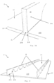
- Fig. 3d shows a perspective top view of an embodiment of an inventive Concrete ceiling element 2.
- Fig. 3a is also in Fig. 3b a plug-fit connection between an FRC plate 100, which provides the base structure 10 with the top side 11, and an FRC web 20 is shown.
- the extension 204 of the support 201 of the FRC web 20 is embedded in an elongated recess 110 in the FRC plate 100, which is part of the base structure 10 with the surface 11.
- the elongated recess 110 and the elongated extension 204 both have a cross-section in the form of a wedge with only one inclined plane and are connected to one another by a filler 31.
- Fig.4 shows a perspective top view of an embodiment of a concrete ceiling element 2 according to the invention.
- Its basic structure 10 consists of an FRC plate 100, on the upper side of which, which upper side is identical to the upper side 11 of the basic structure 10, two FRC webs 20 are arranged. These FRC webs 20 are aligned parallel to one another and are constructed identically to one another.
- Each FRC web 20 has twelve arched recesses 202 and thirteen supports 201 (for the sake of clarity, only one recess 202 and one support 201 for one of the two FRC webs 20 are provided with reference numerals).
- Such a concrete ceiling element 2 can be used to produce a concrete ceiling, with the FRC plate 100 serving as the lower formwork and tension belt and the FRC webs 20 acting as the compression belt.
- the FRC plate 100 of the base structure 10 as well as the FRC plate(s) (not shown) from which the FRC webs 20 cut, for example, were prestressed only in the longitudinal direction or in the longitudinal and transverse directions.
- neither the longitudinally stressed fibers are connected to the transversely stressed fibers nor the longitudinally stressed fibers or the transversely stressed fibers are connected to each other.
- the fibers for longitudinal stressing and the fibers for transverse stressing can be arranged in several layers. Prestressing is done with fibers (e.g.
- fiber includes both a single or several elongated and flexible reinforcement elements, e.g. single filaments, multifilaments, fiber bundles (e.g. stranded or twisted), wires, or one or more rovings (typically comprising 2,000 to approx. 16,000 filaments).
- the net cross-sectional area of the fibers is, for example, less than approximately 5 mm 2 and is in particular in a range from approximately 0.1 mm 2 to approximately 1 mm 2 .
- the tensile strength of the fibers in relation to their net cross-sectional area is, for example, greater than approximately 1000 N/mm 2 , in particular greater than approximately 1800 N/mm 2 .
- the elastic tensile elongation capacity of the fibers is, for example, greater than approximately 1%.
- the fibers, in particular carbon fibers can be tensioned with a tension of approximately 50% to approximately 95%, in particular of at least approximately 80%, in particular at least approximately 90%, of the breaking stress of the fibers.
- the reinforcement spacing is less than or equal to twice the height of the FRC plate.
- the reinforcement content of an FRC plate is, for example, more than 20 mm 2 /m width.
- a stress of at least approx. 30 kN/m or at least approx. 300 kN/m is generated, depending on the load requirements of the FRC plate (dimensioning force).
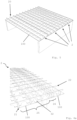
- Fig.5 shows a perspective top view of four concrete ceiling elements 2 of the same design arranged next to one another.
- Each concrete ceiling element 2 has three identically designed FRC webs 20 that run parallel to one another and extend along the entire length of the respective FRC plate 100 on which they are arranged and end flush with it with one of their supports.
- the total of four FRC plates 100 are arranged flush and each end is supported on a side wall.
- Adjacent FRC plates 100 are connected to one another on the adjacent sides.
- a binding agent is applied along the contact surface of the adjacent sides of the FRC plates 100 (not visible in the figure).
- the three FRC webs 20 are arranged on the FRC plates 100 in such a way that placing several FRC plates 100 next to each other results in a large FRC plate with equidistant and parallel arranged FRC webs 20.
- Fig. 6a shows a perspective top view of an embodiment of an inventive Concrete ceiling element 2, which rests on ceiling supports (in the section shown, a ceiling support can be seen on the front right).
- the concrete ceiling element 2 has both longitudinal FRC webs 21 and transverse FRC webs 22.
- the longitudinal FRC webs 21 end with a support flush with the FRC plate 100, while the transverse FRC webs 22 end with a recess flush with the FRC plate 100.
- the transverse FRC webs 22 are arranged equidistantly from one another, while the longitudinal FRC webs 21 have an area 25 with an equidistant but wider arrangement from one another and an area 26 with an equally equidistant but narrower arrangement from one another.
- the area 26 of the narrower FRC web arrangement provides longitudinal reinforcement above the ceiling supports.
- adjacent FRC panels 100 are connected to one another by gluing a lamella as a connecting element 32 over the entire length of the FRC panels 100 along the contact surface of the adjacent sides. Thanks to the FRC webs 22, which also run in the transverse direction, and the glued-on connecting strips 32, ceilings with any free span width can be built in both directions, although the individual FRC panels 100 are usually limited in width in one direction (due to transport).
- Fig. 6b shows a schematic side view of a ceiling element 2
- Fig. 6c a schematic Top view of this concrete ceiling element 2.
- It shows a longitudinal FRC web 21, which is arranged on an FRC plate 100.
- two transverse FRC webs 22 are also visible.
- the transverse FRC webs 22 In order to enable the transverse FRC webs 22 to be attached to the longitudinal FRC web 21, the latter has a groove 203 that opens upwards at the interfaces.
- the grooves 203 are wider than the transverse FRC webs 22 are wide.
- a cavity is created to the left and right of the transverse FRC webs 22 at the interfaces, which cavity is at least partially filled with a filler 31, such as mortar, in order to create a connection between the longitudinal and transverse webs 21, 22, which can absorb tensile forces.
- a filler 31 such as mortar
- Fig. 6d a schematic section through a concrete ceiling element 2. More precisely, it is a cross-section which goes through an FRC web aligned in a first direction, here a longitudinal FRC web 21. Also visible is a section through one of the FRC webs 22 running transversely to this longitudinal FRC web 21, which appears to be split in two by the longitudinal FRC web 21.
- the FRC webs 21, 22 are arranged on an FRC plate 100.
- the longitudinal FRC web 21 has a cavity 205 into which two reinforcements 33 in the form of reinforcement rods are inserted and cast with a filler 31.
- Such a design enables the absorption of high tensile forces.
- such reinforcements 33 as here indicated by dashed lines, also run crosswise.
- transverse FRC web 21 not only the transverse FRC web 21 but also the longitudinal FRC web 22 has a cavity (not visible in this illustration) in which, for example, two reinforcing bars embedded in a filler (indicated by dashed lines) are located. So that longitudinal and transverse reinforcements do not interfere with each other, they are preferably arranged in different levels.
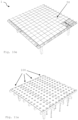
- Fig. 7a shows a perspective top view of an embodiment of a concrete ceiling element 2 according to the invention.
- the FRC webs 20 are arranged in relation to one another in such a way that they form a type of cassette structure which has individual spaces 30 delimited by the FRC webs 20.
- the concrete ceiling to be formed on the concrete ceiling element 2 shown can be reinforced, for example by pouring individual spaces 30 with a binding agent 31, such as concrete, and thus forming point reinforcements.
- the Fig. 7b shows a perspective top view of an embodiment of a concrete ceiling element 2 according to the invention comparable to that in Fig. 7a shown. However, the selective reinforcement by filling a space 30 with concrete 31 is cut here.
- Fig.8 shows a perspective top view of two concrete ceiling elements 2 according to the invention which are connected to one another, the connection of which is achieved both by means of a connecting element 32 fixed by a binding agent and by gluing together the aligned, mutually facing sides of the adjacent FRC panels 100.
- the longitudinal FRC webs 21 are aligned such that they run parallel to the contact surface of the adjacent sides of the FRC panels 100
- the transverse FRC webs 22 are aligned such that the contact surface of the adjacent sides of the FRC panels 100 is spanned by one of the recesses 202.
- the connecting element 32 is laid through the congruent, arched recesses 202 of the transverse FRC webs 22 which form a row.
- Fig.9 shows a perspective top view of a concrete ceiling 1 according to the invention partially provided with a covering layer 50.
- longitudinal FRC webs 21 and transverse FRC webs 22 are arranged, which partially have a cavity 205 in the form of a slot.
- the cavities 205 are open at the top, i.e. their opening points away from the top 11, so that tension elements (e.g. reinforcing iron, FRCK rods or the like) can be inserted from above and cast with a binding agent, such as mortar, in order to provide additional reinforcement.
- tension elements e.g. reinforcing iron, FRCK rods or the like
- the cavities 205 shown are not (yet) filled with tension element and mortar.
- a covering layer 50 can be applied to the plane formed by the FRC webs 21, 22, for example by supporting parquet boards on the FRC webs 21, 22.
- FIG. 10a A method according to the invention for producing a concrete ceiling 1 is described in the Figures 10a to 10e shown perspective views.
- a first in Fig. 10a In the step shown, several concrete ceiling elements 2 (here four in number) are provided on a scaffold, for example formed by wooden struts and ceiling supports. These concrete ceiling elements 2 are then in a second step, as shown in Fig. 10b visible, aligned with each other, in such a way that they form a large area (here a large rectangle) and are arranged flush with each other in all spatial directions.
- Fig. 10b To fix the relative position of the individual concrete ceiling elements 2 to each other, they are then at least partially glued together (not shown).
- transverse FRC webs 22 are arranged on the top side 11 in order to achieve reinforcement.
- the transverse FRC webs 22 are, for example, attached to the already existing longitudinal webs 21, e.g. by means of grooves in the longitudinal FRC webs 21 and transverse FRC webs 22 which are aligned with one another.
- extensions located on the supports of the transverse FRC webs 22 can be inserted into recesses 110 located on the upper side 11 of the basic structure and fixed therein with a binding agent, such as mortar, by filling.
- the framework can then be assembled as shown in Fig.
- FIG. 11a A further method according to the invention for producing a concrete ceiling 1 is described in the Figures 11a to 11e shown perspective top views.
- a first step at least one FRC plate 100 is provided. If several FRC plates 100 (here there are four in number, as in Fig. 11a shown), these FRC plates 100 are aligned flush with each other in such a way that a large (usually rectangular) surface is created. In order to connect the individual FRC plates 100 together, they are glued along the contact surfaces of adjacent FRC plates 100, as shown in Fig.
- a binding agent can be applied directly to the contact surfaces and, on the other hand, alternatively or additionally, a connecting element 32, such as a lamella, can be glued to the upper side 11 along the contact surfaces of adjacent FRC plates 100.
- a connecting element 32 such as a lamella
- cables 40 are laid. If this step is carried out before the FRC webs are arranged, the cables 40 should be laid in such a way that they do not collide with the places intended for fastening the FRC webs 20 to be arranged later. Such places can be, for example, recesses 110 for receiving the supports of the FRC webs 20. In the embodiment shown, these are evenly distributed over the individual FRC plates 100 and are cross-shaped in plan view.
- the step shown which can alternatively be carried out before laying the cables 40, includes the attachment of FRC webs 20 on the upper side 11 of the basic structure 10 formed by the FRC plates 100, among others.
- FRC webs of one orientation eg longitudinal FRC webs 21
- FRC webs of another orientation eg transverse FRC webs 22
- fastening methods such as screwing
- the FRC webs 20 can be attached in particular by the method already described (see Fig. 3a and 3b ) plug-fit connection.
- the cross-shaped arrangement of the FRC webs 21,22 provide the basic structure 10 with sufficient stability so that only four beams or supports, one per corner, are needed to support the basic structure 10.
- the basic structure 10 would also be sufficiently stable to stand on only three supports in the form of three beams.
- the remaining roof supports can be removed (see Fig. 11e , in which the framework is no longer present).
- cooperating means which enable them to be plugged into one another or onto one another.
- Such means can generally be complementary shapes, such as grooves aligned with one another or complementary projections and recesses.
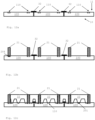
- FIG. 12a shows a basic structure 10 with a top side 11, which is composed of three FRC plates 100 arranged next to one another.
- the FRC plates 100 are connected to one another via connecting elements 32 attached to the top side 11.
- the FRC plates 100 have recesses 110 for receiving supports or the extension or the extensions of the supports of FRC webs Since this is a side view and the recesses 110 of this embodiment do not extend through the entire length of the FRC plates 100 (which may well be the case in other embodiments), they are only shown in dashed lines to illustrate their offset into the image plane.
- two longitudinal FRC webs 21 per FRC plate 100 are preferably arranged by means of a plug-fit connection with the aid of the indicated recesses 110 and the extensions 201 of the supports of the FRC webs 21.
- the extensions 201 are also shown in dashed lines because they are offset into the image plane.
- the transverse FRC webs 22 these can be inserted in individual fragments between the existing longitudinal FRC webs 21. The fragments are held in place, for example, by gluing them to the adjacent longitudinal FRC webs 21, for example using a filler or binding agent such as mortar or the like.
- the fragments can also be conical at the end, i.e. pointing in the direction of the adjacent longitudinal FRC webs 21, and thus be clamped between the longitudinal FRC webs 21.
- the conical shape is shown, for example, in the transverse FRC web 22 on the left in the picture.
- a gap remains in the lower area near the top 11, which could be filled with a filler, but can just as easily be left free.
- the fragments of the transverse FRC webs 22 are their supports or the extensions 201 of these supports are preferably arranged on the FRC plates 100 by means of plug-fit connections.
- only one extension 204 is provided with reference numerals.
- the recesses 110 in which these are inserted are shown in the Fig. 12a and 12b not shown and in the Fig. 12c provided with a reference symbol only once.
- the plug-fit connection serves to connect an FRC web 20 to the base structure 10 in sections.
- the base structure 10 has an upper side 11 and comprises at least one FRC plate 100.
- the FRC plate 100 in turn has at least one recess 110, which in the examples shown here has a wedge shape in cross section and is open towards the upper side 11.
- the extension 204 of a support of the FRC element 20, which also has a wedge shape in cross section, projects into the recess 110.
- the size of the recess 110 is selected such that the extension 204 can be introduced into it from the upper side 11.
- the extension 204 is fixed in the recess 110 using a filling agent 31.
- a filling agent 31 In addition to agents such as mortar, sand, etc., a simple plate with a rectangular cross-section (see Fig. 13a ), a wedge (see Fig. 13c ) or two preferably oppositely aligned wedges (see Fig. 13b ) used to clamp the extension 204 in the recess 110 and thus connect the FRC web 20 to the base structure 10.
Landscapes
- Engineering & Computer Science (AREA)
- Architecture (AREA)
- Civil Engineering (AREA)
- Structural Engineering (AREA)
- Physics & Mathematics (AREA)
- Electromagnetism (AREA)
- Panels For Use In Building Construction (AREA)
- Finishing Walls (AREA)
- Bridges Or Land Bridges (AREA)
- Reinforcement Elements For Buildings (AREA)
- Floor Finish (AREA)
Claims (20)
- Élément de plancher en béton (2) comprenant :- une structure de base (10) plane avec une surface supérieure (11) et comprenant au moins une plaque de béton FRC (béton renforcé de fibres) (100) ; et- au moins une entretoise de béton FRC (20),dans lequel la au moins une entretoise de béton FRC (20) est disposée sur la surface supérieure (11) et est raccordée par endroits à la structure de base (10), dans lequel la au moins une entretoise de béton FRC (20) présente au moins deux supports (201) qui permettent la liaison par endroits avec la structure de base (10), et dans lequel :- au moins un support (201) présente au moins un prolongement (204) orienté vers l'extrémité et la surface supérieure (11), lequel prolongement (204) est agencé dans un évidement (110) d'une plaque de béton FRC (100) de la structure de base (10) et est fixé dans cet évidement (110) dimensionné plus grand que le prolongement (204) ; et/ou- au moins une plaque de béton FRC (100) de la structure de base (10) présente au moins un prolongement (204) sur la surface supérieure (11), lequel prolongement (204) est agencé dans un évidement (110) d'un support (201) orienté vers l'extrémité et la surface supérieure (11) et est fixé dans cet évidement (110) dimensionné plus grand que le prolongement (204).
- Élément de plancher en béton (2) selon la revendication 1, dans lequel un évidement (202) est prévu entre les au moins deux supports (201).
- Élément de plancher en béton (2) selon l'une des revendications 1 à 2 comprenant au moins deux entretoises de béton FRC (20), les entretoises de béton FRC (20) étant disposées parallèlement entre elles et/ou suivant un angle inférieur à 180° et supérieur à 0°, en particulier de façon perpendiculaire entre elles.
- Élément de plancher en béton (2) selon la revendication 3, dans lequel au moins une partie des entretoises de béton FRC (20) agencées parallèles entre elles sont disposées à équidistance les unes des autres, ou dans lequel une partie des entretoises de béton FRC (20) agencées parallèles entre elles ne sont pas disposées de façon équidistante par rapport à une autre partie des entretoises de béton FRC (20) agencées parallèles entre elles, de façon à former au moins une zone avec une densité plus élevée d'entretoises de béton FRC.
- Élément de plancher en béton (2) selon l'une des revendications 1 à 4, comprenant au moins deux entretoises de béton FRC (20), au moins deux des entretoises de béton FRC (20) étant disposées entre elles suivant un angle inférieur à 180° et supérieur à 0°, en particulier de façon perpendiculaire entre elles, de sorte que les au moins deux entretoises de béton FRC (20) se coupent en un point et qu'elles s'emboîtent au niveau de ce point, les au moins deux entretoises de béton FRC (20) présentant de préférence une rainure opposée (203) au niveau du point de coupe, la profondeur des rainures (203) correspondant au moins à la hauteur des entretoises de béton FRC (20) au niveau du point de coupe.
- Élément de plancher en béton (2) selon l'une des revendications 3 à 5, dans lequel au moins trois, en particulier au moins quatre, des entretoises de béton FRC (20) sont disposées les unes par rapport aux autres de façon à entourer un espace (30), lequel espace (30) étant au moins en partie coulé avec du béton.
- Élément de plancher en béton (2) selon l'une des revendications 1 à 6, dans lequel au moins une des entretoises de béton FRC (20) est réalisée pleine et/ou au moins une des entretoises de béton FRC (20) présente au moins une cavité (205), en particulier sous la forme d'une fente, la au moins une cavité étant en particulier pourvue d'un élément de traction, plus particulièrement d'une barre de traction, et étant en particulier remplie au moins partiellement d'un matériau de remplissage (31), de préférence de mortier.
- Élément de plancher en béton (2) selon l'une des revendications 1 à 7, dans lequel la structure de base (10) comprend au moins deux plaques de béton FRC (100) adjacentes et disposées à plat l'une à côté de l'autre, dans lequel en particulier les plaques de béton FRC (100) sont collées au moins en partie le long de leurs côtés se faisant face.
- Élément de plancher en béton (2) selon la revendication 8, dans lequel au moins un élément de liaison (32), en particulier une pièce de liaison, est appliqué(e) au moins partiellement sur la surface supérieure (11) le long des côtés orientés l'un vers l'autre des plaques de béton FRC (100) adjacentes et disposées à plat l'une à côté de l'autre.
- Élément de plancher en béton (2) selon l'une des revendications 1 à 9, dans lequel le au moins un prolongement (204) et l'évidement (110) présentent en coupe transversale la forme d'une cale, en particulier d'une cale avec un ou deux plans inclinés, ou dans lequel le prolongement (204) et l'évidement (110) présentent en coupe transversale la forme d'une cale avec uniquement un plan incliné.
- Élément de plancher en béton (2) selon l'une des revendications 1 à 10, dans lequel la dimension de l'évidement (110) et la dimension du prolongement (204) sont adaptées l'une à l'autre de sorte que le prolongement (204) puisse être assemblé dans le sens transversal, l'évidement (110) étant réalisé plus grand à son endroit le plus étroit que le prolongement (204) à son endroit le plus large.
- Plancher en béton (1) comprenant au moins un élément de plancher en béton (2) selon l'une des revendications 1 à 11.
- Plancher en béton (1) selon la revendication 12, comprenant au moins une conduite (40) qui est disposée sur la surface supérieure (11) de la structure de base (10) et qui est guidée à travers au moins un évidement (202) d'une entretoise de béton FRC (20), et/ou comprenant une couche de recouvrement (50) supportée sur les entretoises de béton FRC (20), en particulier une couche de recouvrement (50) comprenant des dalles de plancher en bois et/ou en pierre et/ou en béton FRC.
- Utilisation d'un assemblage par emboîtement pour raccorder deux éléments en béton FRC (100, 20), l'assemblage par emboîtement étant composé d'un prolongement d'un élément en béton FRC venant s'engager dans un évidement d'un élément en béton FRC et d'un matériau de remplissage, l'évidement étant dimensionné plus grand que le prolongement, et le prolongement étant ajusté dans l'évidement avec le matériau de remplissage, de sorte que la liaison par correspondance de forme de l'assemblage par emboîtement n'est obtenue que par le matériau de remplissage.
- Procédé pour fabriquer un plancher en béton (1) comprenant les étapes consistant à :- fournir au moins un élément de plancher en béton (2) selon l'une des revendications 1 à 11 ; et- installer au moins une conduite (40) sur la surface supérieure (11) de la structure de base (10) et guider cette conduite (40) à travers au moins un évidement (202) d'une entretoise de béton FRC (20) ; et/ou- appliquer une couche de recouvrement (50) sur les entretoises de béton FRC (20).
- Procédé pour fabriquer un plancher en béton (1) selon la revendication 15, consistant à :- fournir au moins deux éléments de plancher en béton (2) selon l'une des revendications 1 à 11 ; et- disposer les au moins deux éléments de plancher en béton (2) à plat, l'un à côté de l'autre ; puis en particulier- coller les au moins deux éléments de plancher en béton (2) au moins en partie le long de leurs côtés orientés l'un vers l'autre ; et/ou en particulier- installer au moins un élément de liaison (32) sur la surface supérieure (11) au moins en partie le long des côtés orientés l'un vers l'autre des éléments de plancher en béton (2) adjacents et disposés à plat l'un à côté de l'autre.
- Procédé pour fabriquer un plancher en béton (1) consistant à :- fournir au moins une plaque de béton FRC (100) pour former une structure de base (10), la plaque de béton FRC (100) présentant au moins un évidement (110) qui présente notamment une section transversale en forme de cale, ou présentant au moins un prolongement (204) sur la surface supérieure (11), lequel prolongement présentant notamment une section transversale en forme de cale ;- installer en particulier au moins une conduite (40) sur la surface supérieure (11) de la structure de base (10), de préférence de sorte que le au moins un évidement (110) ou le au moins un prolongement (204) reste libre ;- installer au moins une entretoise de béton FRC (20) avec au moins deux supports sur la surface supérieure (11) de la structure de base (10) en insérant un prolongement (204) des supports (201) de l'entretoise de béton FRC (20) dans le au moins un évidement (110) de la plaque de béton FRC (100) et fixer le prolongement (204) dans l'évidement (110) à l'aide d'un matériau de remplissage (31), le prolongement présentant notamment une section transversale en forme de cale, ou- installer au moins une entretoise de béton FRC (20) avec au moins deux supports sur la surface supérieure (11) de la structure de base (10) en insérant le prolongement (204) de la surface supérieure (11) de la plaque de béton FRC (100) dans un évidement (110) des supports (201) de l'entretoise de béton FRC (20) et fixer le prolongement (204) dans l'évidement (110) à l'aide d'un matériau de remplissage (31) ;- appliquer une couche de recouvrement (50) sur l'entretoise de béton FRC (20).
- Procédé pour fabriquer un plancher en béton (1) selon la revendication 17, consistant à :- installer au moins une entretoise de béton FRC (20) sur la surface supérieure (11) de la structure de base (10), en particulier suivant un angle inférieur à 180° et supérieur à 0° par rapport à la au moins une entretoise de béton FRC (20) déjà installée, et/ou consistant en particulier à insérer la au moins une entretoise de béton FRC (20) supplémentaire sur au moins une entretoise de béton FRC (20) déjà installée.
- Procédé pour fabriquer un plancher en béton (1) selon la revendication 17 ou 18, consistant à :- fournir au moins deux plaques de béton FRC (100) pour former une structure de base (10), en particulier deux plaques de béton FRC (100) présentant en coupe transversale des évidements (110) en forme de cale ;- installer les au moins deux plaques de béton FRC (100) à plat l'une à côté de l'autre ;- coller les au moins deux plaques de béton FRC (100) au moins en partie le long de leurs côtés orientés l'un vers l'autre ; et/ou- installer en particulier au moins un élément de liaison (32) sur la surface supérieure (11) au moins en partie le long des côtés orientés l'un vers l'autre des plaques de béton FRC (100) adjacentes et installées à plat l'une à côté de l'autre.
- Procédé pour fabriquer un élément de plancher en béton (2) selon l'une des revendications 1 à 11, consistant à :- fournir au moins une plaque de béton FRC (100) pour former une structure de base (10), en particulier une plaque de béton FRC (100) avec des évidements (110) en forme de cale en coupe transversale ;- installer au moins une entretoise de béton FRC (20) sur la surface supérieure (11) de la structure de base (10) en insérant un prolongement (204) des supports (201) de l'entretoise de béton FRC (20) dans un évidement (110), et en particulier fixer le prolongement (204) dans l'évidement (110) à l'aide d'un matériau de remplissage, ou en insérant un prolongement (204) de la plaque de béton FRC (100) dans un évidement (110) des supports (201) de l'entretoise de béton FRC (20) et fixer le prolongement (204) dans l'évidement (110) à l'aide d'un matériau de remplissage ;- en particulier installer au moins une autre entretoise de béton FRC (20) sur la surface supérieure (11) de la structure de base (10), de préférence suivant un angle inférieur à 180° et supérieur à 0° par rapport à la au moins une entretoise de béton FRC (20) déjà installée et/ou de préférence insérer la au moins une entretoise de béton FRC (20) supplémentaire sur la au moins une entretoise de béton FRC (20) déjà installée.
Priority Applications (2)
| Application Number | Priority Date | Filing Date | Title |
|---|---|---|---|
| HUE19766004A HUE069758T2 (hu) | 2019-09-06 | 2019-09-06 | Betonfödém, betonfödémelem és eljárás egy betonfödém, valamint egy betonfödémelem elõállítására |
| PL19766004.6T PL4025744T3 (pl) | 2019-09-06 | 2019-09-06 | Strop betonowy, betonowe elementy stropowe oraz sposób wytwarzania stropu betonowego i betonowego elementu stropowego |
Applications Claiming Priority (1)
| Application Number | Priority Date | Filing Date | Title |
|---|---|---|---|
| PCT/EP2019/073887 WO2021043428A1 (fr) | 2019-09-06 | 2019-09-06 | Plancher en béton, éléments de plancher en béton et procédés de fabrication d'un plancher en béton et d'un élément de plancher en béton |
Publications (2)
| Publication Number | Publication Date |
|---|---|
| EP4025744A1 EP4025744A1 (fr) | 2022-07-13 |
| EP4025744B1 true EP4025744B1 (fr) | 2024-09-25 |
Family
ID=67909394
Family Applications (1)
| Application Number | Title | Priority Date | Filing Date |
|---|---|---|---|
| EP19766004.6A Active EP4025744B1 (fr) | 2019-09-06 | 2019-09-06 | Plancher en béton, éléments de plancher en béton et procédés de fabrication d'un plancher en béton et d'un élément de plancher en béton |
Country Status (13)
| Country | Link |
|---|---|
| US (1) | US12031315B2 (fr) |
| EP (1) | EP4025744B1 (fr) |
| JP (1) | JP7462031B2 (fr) |
| CN (1) | CN114599843A (fr) |
| AU (1) | AU2019464926B2 (fr) |
| CA (1) | CA3149437A1 (fr) |
| DK (1) | DK4025744T3 (fr) |
| ES (1) | ES2998201T3 (fr) |
| FI (1) | FI4025744T3 (fr) |
| HU (1) | HUE069758T2 (fr) |
| PL (1) | PL4025744T3 (fr) |
| PT (1) | PT4025744T (fr) |
| WO (1) | WO2021043428A1 (fr) |
Cited By (1)
| Publication number | Priority date | Publication date | Assignee | Title |
|---|---|---|---|---|
| EP4038246A1 (fr) * | 2019-10-04 | 2022-08-10 | Kolja Kuse | Poutre en pierre et matériau stable à la traction |
Families Citing this family (5)
| Publication number | Priority date | Publication date | Assignee | Title |
|---|---|---|---|---|
| WO2023088555A1 (fr) * | 2021-11-17 | 2023-05-25 | Cpc Ag | Élément de jonction de béton destiné à relier des dalles de béton, construction de dalle de béton dotée d'un tel élément de jonction, et procédés de production de celui-ci |
| DE102021130472A1 (de) * | 2021-11-22 | 2023-05-25 | Fertigbau Lindenberg OTTO Quast GmbH & Co. KG | Regalboden aus Beton |
| DE102022116063A1 (de) * | 2022-06-28 | 2023-12-28 | Rheinisch-Westfälische Technische Hochschule Aachen, abgekürzt RWTH Aachen, Körperschaft des öffentlichen Rechts | Mehrschichtiges Bauelement für eine Decke, Verfahren zur Herstellung eines mehrschichtigen Bauelements und Verwendung von Textilbetonstreifen |
| WO2025162590A1 (fr) | 2024-02-02 | 2025-08-07 | Cpc Ag | Raccord en forme de pignon, pièce de jonction raccordable en forme de pignon et production associée, procédé d'assemblage de pièces de jonction, utilisation d'un raccord en forme de pignon pour assembler des pièces de jonction, et composant assemblé en plusieurs parties |
| DE102024111006B4 (de) * | 2024-04-19 | 2026-01-29 | Betonwerk Oschatz GmbH | Hohldeckenplatte und Verfahren zu ihrer Herstellung |
Citations (1)
| Publication number | Priority date | Publication date | Assignee | Title |
|---|---|---|---|---|
| CA2777124A1 (fr) * | 2012-05-17 | 2013-11-17 | Key Concrete Products Ltd. | Structures de beton manufacture |
Family Cites Families (41)
| Publication number | Priority date | Publication date | Assignee | Title |
|---|---|---|---|---|
| USRE22569E (en) * | 1944-11-28 | Concave reinforced concrete beam | ||
| US1484206A (en) * | 1920-10-09 | 1924-02-19 | Joseph A Birkholz | Building unit |
| US2039183A (en) * | 1934-03-21 | 1936-04-28 | George E Nagel | Precast concrete roof deck slab |
| US2047109A (en) * | 1935-12-16 | 1936-07-07 | George E Nagel | Precast insulated concrete deck slab |
| US2769332A (en) * | 1950-12-18 | 1956-11-06 | Jr Charles Kepler Brown | Preformed slab and shell construction |
| US3475529A (en) * | 1966-12-23 | 1969-10-28 | Concrete Structures Inc | Method of making a prestressed hollow concrete core slab |
| FR1511948A (fr) * | 1967-02-20 | 1968-02-02 | Travaux Pour La Construction E | Procédé pour la fabrication d'un plancher en béton armé à dalles nervurées modulées et préfabriquées |
| US3707819A (en) * | 1970-12-01 | 1973-01-02 | W Calhoun | Decking system |
| US3841206A (en) * | 1973-09-11 | 1974-10-15 | Is Inc Systems Co | Multiple zone building structure |
| US4096068A (en) * | 1976-08-19 | 1978-06-20 | Peabody Galion Corporation | Cast beams for filterbed with cross flow at ends |
| US4387544A (en) * | 1979-05-25 | 1983-06-14 | Schilger Herbert K | Reinforcing strips for pre-cast construction elements |
| US4555888A (en) * | 1982-12-06 | 1985-12-03 | Joseph Goldenberg | Preformed, reinforced structural panels and method of making same |
| US4702048A (en) * | 1984-04-06 | 1987-10-27 | Paul Millman | Bubble relief form for concrete |
| DE3431118C1 (de) * | 1984-08-24 | 1985-04-04 | MERO-Werke Dr.-Ing. Max Mengeringhausen, GmbH & Co, 8700 Würzburg | Freitragende Verbundbauplatte,insbesondere fuer Doppelboeden |
| CA1308271C (fr) * | 1988-11-25 | 1992-10-06 | John R. Spronken | Dispositif d'assemblage d'elements de construction en beton |
| JP2772677B2 (ja) | 1989-06-23 | 1998-07-02 | 株式会社竹中工務店 | カーボン繊維で補強した中空床スラブ及びその製造方法 |
| JP2748709B2 (ja) | 1991-02-27 | 1998-05-13 | 鹿島建設株式会社 | プレストレストコンクリート合成スラブ |
| JP3026058B2 (ja) * | 1994-11-01 | 2000-03-27 | 三井造船株式会社 | Pc合成床版 |
| JPH09144200A (ja) * | 1995-11-28 | 1997-06-03 | Nippon Cement Co Ltd | コンクリート製押出成形板 |
| US5946872A (en) * | 1998-01-22 | 1999-09-07 | Pardo; Jorge | Method and apparatus for constructing suspended concrete floors and roofs |
| US5950390A (en) * | 1998-04-20 | 1999-09-14 | Jones; Jack | Pre-cast concrete building module |
| US6101779A (en) * | 1998-05-20 | 2000-08-15 | Space Master Building Systems, Llc | Construction unit for a modular building |
| CA2468523A1 (fr) * | 2001-11-28 | 2003-06-05 | Weiling Peng | Panneau de construction a bord adhesif et son procede de fabrication |
| US7937901B2 (en) * | 2005-03-29 | 2011-05-10 | Sarkkinen Douglas L | Tendon-identifying, post tensioned concrete flat plate slab and method and apparatus for constructing same |
| US20080092466A1 (en) | 2006-10-20 | 2008-04-24 | Zmz Precast, Inc. | Precast Concrete I-Beam Deck with Pre-Stressed Wire Strands as Reinforcing Material |
| US10619347B2 (en) * | 2007-08-22 | 2020-04-14 | California Expanded Metal Products Company | Fire-rated wall and ceiling system |
| JP2010168759A (ja) * | 2009-01-21 | 2010-08-05 | Katayama Stratec Kk | 格子状構造材の製造方法及び格子状構造材 |
| GB2477319B (en) * | 2010-01-29 | 2016-08-10 | Precast Advanced Track Ltd | Modular slab and modular surface system |
| NL2004864C2 (en) | 2010-06-09 | 2011-12-13 | Infra & B V | Moulds and methods for forming prefab concrete floor elements and prefab elements. |
| ES2356546B2 (es) | 2010-06-28 | 2011-09-14 | Alberto Alarcón García | Un forjado o elemento estructural similar aligerado por el que pueden discurrir instalaciones registrables. |
| CN102535710A (zh) | 2010-12-30 | 2012-07-04 | 湖南高岭建设集团股份有限公司 | 一种带肋钢筋混凝土预制板 |
| JP2015110860A (ja) | 2012-03-27 | 2015-06-18 | 国立大学法人大阪大学 | 床材及びこの床材を組み合わせた路面の床構造 |
| PT2912239T (pt) | 2012-09-17 | 2023-05-09 | Cpc Ag | Elemento de reforço para produção de componentes de betão pré-esforçado, componente de betão e processos de produção |
| AU2014277350B2 (en) * | 2013-06-04 | 2017-11-16 | Abeo ApS | A method of making a building element, an apparatus for making the building element, and a building element made by the method |
| US9388562B2 (en) * | 2014-05-29 | 2016-07-12 | Rocky Mountain Prestress, LLC | Building system using modular precast concrete components |
| US10041289B2 (en) * | 2014-08-30 | 2018-08-07 | Innovative Building Technologies, Llc | Interface between a floor panel and a panel track |
| US11054148B2 (en) * | 2014-08-30 | 2021-07-06 | Innovative Building Technologies, Llc | Heated floor and ceiling panel with a corrugated layer for modular use in buildings |
| DE102015113484A1 (de) | 2015-08-14 | 2017-02-16 | Bernd Iglauer | Flächiges Bauelement, aussteifende Scheibe, Gebäudemodul und mehrstöckiges Gebäude |
| US20170268242A1 (en) * | 2016-05-23 | 2017-09-21 | Michael Molinelli | Concrete floor and ceiling system without steel reinforcing |
| US11536017B2 (en) * | 2016-10-26 | 2022-12-27 | Envirokeeper, LLC | Modular precast concrete water storage device and system |
| US10718114B2 (en) * | 2017-10-30 | 2020-07-21 | Samsung C&T Corporation | High-damping reinforced concrete (RC) lattice beam and substructure using same |
-
2019
- 2019-09-06 AU AU2019464926A patent/AU2019464926B2/en active Active
- 2019-09-06 PT PT197660046T patent/PT4025744T/pt unknown
- 2019-09-06 CN CN201980100042.3A patent/CN114599843A/zh active Pending
- 2019-09-06 DK DK19766004.6T patent/DK4025744T3/da active
- 2019-09-06 HU HUE19766004A patent/HUE069758T2/hu unknown
- 2019-09-06 WO PCT/EP2019/073887 patent/WO2021043428A1/fr not_active Ceased
- 2019-09-06 FI FIEP19766004.6T patent/FI4025744T3/fi active
- 2019-09-06 PL PL19766004.6T patent/PL4025744T3/pl unknown
- 2019-09-06 ES ES19766004T patent/ES2998201T3/es active Active
- 2019-09-06 EP EP19766004.6A patent/EP4025744B1/fr active Active
- 2019-09-06 CA CA3149437A patent/CA3149437A1/fr active Pending
- 2019-09-06 US US17/640,292 patent/US12031315B2/en active Active
- 2019-09-06 JP JP2022514821A patent/JP7462031B2/ja active Active
Patent Citations (1)
| Publication number | Priority date | Publication date | Assignee | Title |
|---|---|---|---|---|
| CA2777124A1 (fr) * | 2012-05-17 | 2013-11-17 | Key Concrete Products Ltd. | Structures de beton manufacture |
Cited By (2)
| Publication number | Priority date | Publication date | Assignee | Title |
|---|---|---|---|---|
| EP4038246A1 (fr) * | 2019-10-04 | 2022-08-10 | Kolja Kuse | Poutre en pierre et matériau stable à la traction |
| EP4038246B1 (fr) * | 2019-10-04 | 2026-04-08 | Kolja Kuse | Poutre en pierre et matériau stable à la traction |
Also Published As
| Publication number | Publication date |
|---|---|
| US20220341151A1 (en) | 2022-10-27 |
| ES2998201T3 (en) | 2025-02-19 |
| CA3149437A1 (fr) | 2021-03-11 |
| WO2021043428A1 (fr) | 2021-03-11 |
| JP2022551391A (ja) | 2022-12-09 |
| JP7462031B2 (ja) | 2024-04-04 |
| PT4025744T (pt) | 2024-11-27 |
| AU2019464926B2 (en) | 2025-11-13 |
| DK4025744T3 (da) | 2024-10-21 |
| FI4025744T3 (fi) | 2024-10-28 |
| EP4025744A1 (fr) | 2022-07-13 |
| PL4025744T3 (pl) | 2025-03-24 |
| US12031315B2 (en) | 2024-07-09 |
| AU2019464926A1 (en) | 2022-04-07 |
| HUE069758T2 (hu) | 2025-04-28 |
| CN114599843A (zh) | 2022-06-07 |
Similar Documents
| Publication | Publication Date | Title |
|---|---|---|
| EP4025744B1 (fr) | Plancher en béton, éléments de plancher en béton et procédés de fabrication d'un plancher en béton et d'un élément de plancher en béton | |
| AT396274B (de) | Bewehrungskoerper fuer eine deckenplatte | |
| DE69622036T2 (de) | Betonstahlbauelemente | |
| EP2486196B1 (fr) | Procédé et dispositif pour l'ajout postérieur d'une partie extérieure en saillie à une partie de bâtiment existante | |
| EP2146017A1 (fr) | Composant pour dalles de plancher ou de toiture ainsi que procédé destiné à la fabrication d'un composant | |
| AT511220A1 (de) | Deckenelement zur ausbildung von gebäudedecken | |
| DE60023159T3 (de) | Hohlplatte zur herstellung von einem bodenfeld in welches leitungen eingebaut werden können und verfahren zum herstellen eines bodenfelds mit leitungen | |
| EP0866185B1 (fr) | Système d'isolation thermique | |
| EP1482101B1 (fr) | Elément de construction, procédé pour fabriquer des éléments de construction et moyens de liaison pour élément de construction | |
| DE3410484A1 (de) | Deckenelement | |
| EP1953303B1 (fr) | Elément de construction mural, procédé de fabrication d'un élément de construction mural et dispositif d'ancre pour un élément de construction mural | |
| CH677249A5 (en) | Bridging grid for structural beams - is of rod construction, with short, bent spacer welded between upper and lower horizontals | |
| DE3206163A1 (de) | Bauelement | |
| EP0752033B1 (fr) | Structure constituee d'elements prefabriques | |
| DE3432940A1 (de) | Vorgefertigtes mauerwerk | |
| DE3587713T2 (de) | Abziehlaufschiene. | |
| DE102007004573B4 (de) | Wandbauelement und Verfahren zur Herstellung eines Wandbauelements | |
| DE60011415T2 (de) | Konstruktionselement für gebäude und versteifungsplatte für ein solches element | |
| DE102006021781B4 (de) | Elementwand | |
| EP3754125B1 (fr) | Élément de construction pour le montage dans des joints de dilatation de bâtiments | |
| WO2004072398A1 (fr) | Corps de coffrage perdu | |
| DE102024111006B4 (de) | Hohldeckenplatte und Verfahren zu ihrer Herstellung | |
| EP1918469B1 (fr) | Système de raccordement d'isolation thermique | |
| DE10066165B4 (de) | Wärmedämmverbundsystem sowie bandförmiges Element für die Befestigung von Dämmstoffelementen | |
| DE102004003366B4 (de) | Verfahren zum Herstellen eines Einfamilien-oder Mehrfamilienhauses, Betonfertigteil-Trogplatte für eine Gebäudedecke sowie Fertighaus |
Legal Events
| Date | Code | Title | Description |
|---|---|---|---|
| STAA | Information on the status of an ep patent application or granted ep patent |
Free format text: STATUS: UNKNOWN |
|
| STAA | Information on the status of an ep patent application or granted ep patent |
Free format text: STATUS: THE INTERNATIONAL PUBLICATION HAS BEEN MADE |
|
| PUAI | Public reference made under article 153(3) epc to a published international application that has entered the european phase |
Free format text: ORIGINAL CODE: 0009012 |
|
| STAA | Information on the status of an ep patent application or granted ep patent |
Free format text: STATUS: REQUEST FOR EXAMINATION WAS MADE |
|
| 17P | Request for examination filed |
Effective date: 20220309 |
|
| AK | Designated contracting states |
Kind code of ref document: A1 Designated state(s): AL AT BE BG CH CY CZ DE DK EE ES FI FR GB GR HR HU IE IS IT LI LT LU LV MC MK MT NL NO PL PT RO RS SE SI SK SM TR |
|
| DAV | Request for validation of the european patent (deleted) | ||
| DAX | Request for extension of the european patent (deleted) | ||
| STAA | Information on the status of an ep patent application or granted ep patent |
Free format text: STATUS: EXAMINATION IS IN PROGRESS |
|
| REG | Reference to a national code |
Ref country code: HK Ref legal event code: DE Ref document number: 40075090 Country of ref document: HK |
|
| 17Q | First examination report despatched |
Effective date: 20221222 |
|
| GRAP | Despatch of communication of intention to grant a patent |
Free format text: ORIGINAL CODE: EPIDOSNIGR1 |
|
| STAA | Information on the status of an ep patent application or granted ep patent |
Free format text: STATUS: GRANT OF PATENT IS INTENDED |
|
| INTG | Intention to grant announced |
Effective date: 20240418 |
|
| P01 | Opt-out of the competence of the unified patent court (upc) registered |
Free format text: CASE NUMBER: APP_33741/2024 Effective date: 20240605 |
|
| GRAS | Grant fee paid |
Free format text: ORIGINAL CODE: EPIDOSNIGR3 |
|
| GRAA | (expected) grant |
Free format text: ORIGINAL CODE: 0009210 |
|
| STAA | Information on the status of an ep patent application or granted ep patent |
Free format text: STATUS: THE PATENT HAS BEEN GRANTED |
|
| AK | Designated contracting states |
Kind code of ref document: B1 Designated state(s): AL AT BE BG CH CY CZ DE DK EE ES FI FR GB GR HR HU IE IS IT LI LT LU LV MC MK MT NL NO PL PT RO RS SE SI SK SM TR |
|
| REG | Reference to a national code |
Ref country code: GB Ref legal event code: FG4D Free format text: NOT ENGLISH |
|
| REG | Reference to a national code |
Ref country code: CH Ref legal event code: EP |
|
| REG | Reference to a national code |
Ref country code: DE Ref legal event code: R096 Ref document number: 502019012202 Country of ref document: DE |
|
| REG | Reference to a national code |
Ref country code: DK Ref legal event code: T3 Effective date: 20241018 |
|
| REG | Reference to a national code |
Ref country code: IE Ref legal event code: FG4D Free format text: LANGUAGE OF EP DOCUMENT: GERMAN Ref country code: NL Ref legal event code: FP |
|
| REG | Reference to a national code |
Ref country code: FI Ref legal event code: FGE |
|
| REG | Reference to a national code |
Ref country code: PT Ref legal event code: SC4A Ref document number: 4025744 Country of ref document: PT Date of ref document: 20241127 Kind code of ref document: T Free format text: AVAILABILITY OF NATIONAL TRANSLATION Effective date: 20241121 |
|
| REG | Reference to a national code |
Ref country code: SE Ref legal event code: TRGR |
|
| REG | Reference to a national code |
Ref country code: LT Ref legal event code: MG9D |
|
| PG25 | Lapsed in a contracting state [announced via postgrant information from national office to epo] |
Ref country code: BG Free format text: LAPSE BECAUSE OF FAILURE TO SUBMIT A TRANSLATION OF THE DESCRIPTION OR TO PAY THE FEE WITHIN THE PRESCRIBED TIME-LIMIT Effective date: 20240925 |
|
| PG25 | Lapsed in a contracting state [announced via postgrant information from national office to epo] |
Ref country code: LV Free format text: LAPSE BECAUSE OF FAILURE TO SUBMIT A TRANSLATION OF THE DESCRIPTION OR TO PAY THE FEE WITHIN THE PRESCRIBED TIME-LIMIT Effective date: 20240925 |
|
| PG25 | Lapsed in a contracting state [announced via postgrant information from national office to epo] |
Ref country code: RS Free format text: LAPSE BECAUSE OF FAILURE TO SUBMIT A TRANSLATION OF THE DESCRIPTION OR TO PAY THE FEE WITHIN THE PRESCRIBED TIME-LIMIT Effective date: 20241225 |
|
| REG | Reference to a national code |
Ref country code: GR Ref legal event code: EP Ref document number: 20240402918 Country of ref document: GR Effective date: 20250120 |
|
| PG25 | Lapsed in a contracting state [announced via postgrant information from national office to epo] |
Ref country code: RS Free format text: LAPSE BECAUSE OF FAILURE TO SUBMIT A TRANSLATION OF THE DESCRIPTION OR TO PAY THE FEE WITHIN THE PRESCRIBED TIME-LIMIT Effective date: 20241225 Ref country code: LV Free format text: LAPSE BECAUSE OF FAILURE TO SUBMIT A TRANSLATION OF THE DESCRIPTION OR TO PAY THE FEE WITHIN THE PRESCRIBED TIME-LIMIT Effective date: 20240925 Ref country code: BG Free format text: LAPSE BECAUSE OF FAILURE TO SUBMIT A TRANSLATION OF THE DESCRIPTION OR TO PAY THE FEE WITHIN THE PRESCRIBED TIME-LIMIT Effective date: 20240925 |
|
| REG | Reference to a national code |
Ref country code: ES Ref legal event code: FG2A Ref document number: 2998201 Country of ref document: ES Kind code of ref document: T3 Effective date: 20250219 |
|
| PG25 | Lapsed in a contracting state [announced via postgrant information from national office to epo] |
Ref country code: IS Free format text: LAPSE BECAUSE OF FAILURE TO SUBMIT A TRANSLATION OF THE DESCRIPTION OR TO PAY THE FEE WITHIN THE PRESCRIBED TIME-LIMIT Effective date: 20250125 |
|
| PG25 | Lapsed in a contracting state [announced via postgrant information from national office to epo] |
Ref country code: SM Free format text: LAPSE BECAUSE OF FAILURE TO SUBMIT A TRANSLATION OF THE DESCRIPTION OR TO PAY THE FEE WITHIN THE PRESCRIBED TIME-LIMIT Effective date: 20240925 |
|
| PG25 | Lapsed in a contracting state [announced via postgrant information from national office to epo] |
Ref country code: EE Free format text: LAPSE BECAUSE OF FAILURE TO SUBMIT A TRANSLATION OF THE DESCRIPTION OR TO PAY THE FEE WITHIN THE PRESCRIBED TIME-LIMIT Effective date: 20240925 |
|
| PG25 | Lapsed in a contracting state [announced via postgrant information from national office to epo] |
Ref country code: SK Free format text: LAPSE BECAUSE OF FAILURE TO SUBMIT A TRANSLATION OF THE DESCRIPTION OR TO PAY THE FEE WITHIN THE PRESCRIBED TIME-LIMIT Effective date: 20240925 |
|
| REG | Reference to a national code |
Ref country code: HU Ref legal event code: AG4A Ref document number: E069758 Country of ref document: HU |
|
| REG | Reference to a national code |
Ref country code: DE Ref legal event code: R097 Ref document number: 502019012202 Country of ref document: DE |
|
| PLBE | No opposition filed within time limit |
Free format text: ORIGINAL CODE: 0009261 |
|
| STAA | Information on the status of an ep patent application or granted ep patent |
Free format text: STATUS: NO OPPOSITION FILED WITHIN TIME LIMIT |
|
| 26N | No opposition filed |
Effective date: 20250626 |
|
| PGFP | Annual fee paid to national office [announced via postgrant information from national office to epo] |
Ref country code: NL Payment date: 20250826 Year of fee payment: 7 |
|
| REG | Reference to a national code |
Ref country code: CH Ref legal event code: U11 Free format text: ST27 STATUS EVENT CODE: U-0-0-U10-U11 (AS PROVIDED BY THE NATIONAL OFFICE) Effective date: 20251001 |
|
| PGFP | Annual fee paid to national office [announced via postgrant information from national office to epo] |
Ref country code: DK Payment date: 20250911 Year of fee payment: 7 Ref country code: DE Payment date: 20250819 Year of fee payment: 7 |
|
| PGFP | Annual fee paid to national office [announced via postgrant information from national office to epo] |
Ref country code: GR Payment date: 20250829 Year of fee payment: 7 |
|
| PGFP | Annual fee paid to national office [announced via postgrant information from national office to epo] |
Ref country code: IT Payment date: 20250827 Year of fee payment: 7 Ref country code: PL Payment date: 20250826 Year of fee payment: 7 |
|
| PGFP | Annual fee paid to national office [announced via postgrant information from national office to epo] |
Ref country code: BE Payment date: 20250825 Year of fee payment: 7 Ref country code: GB Payment date: 20250814 Year of fee payment: 7 Ref country code: HU Payment date: 20250915 Year of fee payment: 7 |
|
| PGFP | Annual fee paid to national office [announced via postgrant information from national office to epo] |
Ref country code: AT Payment date: 20250827 Year of fee payment: 7 Ref country code: FR Payment date: 20250821 Year of fee payment: 7 |
|
| PGFP | Annual fee paid to national office [announced via postgrant information from national office to epo] |
Ref country code: CZ Payment date: 20250821 Year of fee payment: 7 |
|
| PGFP | Annual fee paid to national office [announced via postgrant information from national office to epo] |
Ref country code: RO Payment date: 20250901 Year of fee payment: 7 |
|
| PG25 | Lapsed in a contracting state [announced via postgrant information from national office to epo] |
Ref country code: HR Free format text: LAPSE BECAUSE OF FAILURE TO SUBMIT A TRANSLATION OF THE DESCRIPTION OR TO PAY THE FEE WITHIN THE PRESCRIBED TIME-LIMIT Effective date: 20240925 |
|
| PGFP | Annual fee paid to national office [announced via postgrant information from national office to epo] |
Ref country code: CH Payment date: 20251001 Year of fee payment: 7 |
|
| PGFP | Annual fee paid to national office [announced via postgrant information from national office to epo] |
Ref country code: ES Payment date: 20251017 Year of fee payment: 7 |
|
| PG25 | Lapsed in a contracting state [announced via postgrant information from national office to epo] |
Ref country code: FI Free format text: LAPSE BECAUSE OF NON-PAYMENT OF DUE FEES Effective date: 20250906 |