EP4025799B1 - Dispositif anti-retour de transmission de rotation - Google Patents
Dispositif anti-retour de transmission de rotation Download PDFInfo
- Publication number
- EP4025799B1 EP4025799B1 EP20764673.8A EP20764673A EP4025799B1 EP 4025799 B1 EP4025799 B1 EP 4025799B1 EP 20764673 A EP20764673 A EP 20764673A EP 4025799 B1 EP4025799 B1 EP 4025799B1
- Authority
- EP
- European Patent Office
- Prior art keywords
- locking element
- output shaft
- input shaft
- cam
- rotation
- Prior art date
- Legal status (The legal status is an assumption and is not a legal conclusion. Google has not performed a legal analysis and makes no representation as to the accuracy of the status listed.)
- Active
Links
Images


Classifications
-
- F—MECHANICAL ENGINEERING; LIGHTING; HEATING; WEAPONS; BLASTING
- F16—ENGINEERING ELEMENTS AND UNITS; GENERAL MEASURES FOR PRODUCING AND MAINTAINING EFFECTIVE FUNCTIONING OF MACHINES OR INSTALLATIONS; THERMAL INSULATION IN GENERAL
- F16D—COUPLINGS FOR TRANSMITTING ROTATION; CLUTCHES; BRAKES
- F16D41/00—Freewheels or freewheel clutches
- F16D41/06—Freewheels or freewheel clutches with intermediate wedging coupling members between an inner and an outer surface
- F16D41/08—Freewheels or freewheel clutches with intermediate wedging coupling members between an inner and an outer surface with provision for altering the freewheeling action
- F16D41/10—Freewheels or freewheel clutches with intermediate wedging coupling members between an inner and an outer surface with provision for altering the freewheeling action with self-actuated reversing
-
- F—MECHANICAL ENGINEERING; LIGHTING; HEATING; WEAPONS; BLASTING
- F16—ENGINEERING ELEMENTS AND UNITS; GENERAL MEASURES FOR PRODUCING AND MAINTAINING EFFECTIVE FUNCTIONING OF MACHINES OR INSTALLATIONS; THERMAL INSULATION IN GENERAL
- F16D—COUPLINGS FOR TRANSMITTING ROTATION; CLUTCHES; BRAKES
- F16D41/00—Freewheels or freewheel clutches
- F16D41/12—Freewheels or freewheel clutches with hinged pawl co-operating with teeth, cogs, or the like
- F16D41/16—Freewheels or freewheel clutches with hinged pawl co-operating with teeth, cogs, or the like the action being reversible
-
- F—MECHANICAL ENGINEERING; LIGHTING; HEATING; WEAPONS; BLASTING
- F16—ENGINEERING ELEMENTS AND UNITS; GENERAL MEASURES FOR PRODUCING AND MAINTAINING EFFECTIVE FUNCTIONING OF MACHINES OR INSTALLATIONS; THERMAL INSULATION IN GENERAL
- F16D—COUPLINGS FOR TRANSMITTING ROTATION; CLUTCHES; BRAKES
- F16D41/00—Freewheels or freewheel clutches
- F16D41/06—Freewheels or freewheel clutches with intermediate wedging coupling members between an inner and an outer surface
- F16D2041/0606—Freewheels or freewheel clutches with intermediate wedging coupling members between an inner and an outer surface the intermediate coupling members having parts wedging by movement other than pivoting or rolling but combined with pivoting or rolling parts, e.g. shoes on pivot bars or on rollers
-
- F—MECHANICAL ENGINEERING; LIGHTING; HEATING; WEAPONS; BLASTING
- F16—ENGINEERING ELEMENTS AND UNITS; GENERAL MEASURES FOR PRODUCING AND MAINTAINING EFFECTIVE FUNCTIONING OF MACHINES OR INSTALLATIONS; THERMAL INSULATION IN GENERAL
- F16D—COUPLINGS FOR TRANSMITTING ROTATION; CLUTCHES; BRAKES
- F16D41/00—Freewheels or freewheel clutches
- F16D41/06—Freewheels or freewheel clutches with intermediate wedging coupling members between an inner and an outer surface
- F16D41/064—Freewheels or freewheel clutches with intermediate wedging coupling members between an inner and an outer surface the intermediate members wedging by rolling and having a circular cross-section, e.g. balls
- F16D2041/0646—Freewheels or freewheel clutches with intermediate wedging coupling members between an inner and an outer surface the intermediate members wedging by rolling and having a circular cross-section, e.g. balls the intermediate coupling members moving between recesses in an inner race and recesses in an outer race
Definitions
- the present invention relates to rotation transmission devices allowing the transmission of a one-way rotational movement from a driving input shaft to a driven output shaft.
- the present invention aims to constitute a device adaptable to many existing rotation drive devices, in one or two directions of rotation.
- Known rotation transmission devices allowing a transmission of a rotational movement in one direction, from an input shaft to an output shaft, are generally friction-type, which hinders the operation of the system on which they are inserted and does not allow for robustness of the rotation stop elements of the output shaft.
- the known devices often require an external energy supply for the non-return function.
- the document EP0370319A1 describes a non-return device for transmitting a rotational movement according to the preamble of claim 1, comprising two coaxial shafts, a frame for guiding the rotation of the shafts, a locking element movable in radial translation between a locking position and an unlocking position, the input shaft comprising means for switching the locking element between its locking and unlocking positions and with a cam having a profile adapted to move the locking element radially.
- the invention aims to overcome at least one of the aforementioned drawbacks and to propose a non-return device for transmitting a coaxial rotational movement between two shafts which is entirely mechanical and which is capable of combining the advantages of robustness, adaptability and compactness.
- the invention relates to a non-return device for transmitting a rotational movement according to claim 1.
- the switching means of the locking element comprise a cam having a profile adapted to radially move the locking element during rotation of the input shaft.
- the cam is provided on a male end of the input shaft, said male end being engaged in a female end of the output shaft.
- the input shaft comprises a shoulder coming into abutment against a flat of the output shaft to drive the output shaft in rotation, the reaching of the stop by the shoulder during a rotation of the input shaft coinciding angularly with the placing in the unlocked position of the locking element by the cam.
- the switching means of the locking element comprise an unlocking key interposed between the cam and said locking element, said key being linked in translation through the conduit of the output shaft.
- the unlocking key is fully seated within the output shaft conduit in the unlocked position.
- the device comprises elastic return means in the locking position of the locking element, working in compression to push said locking element towards the axis of the shafts against the cam or, where appropriate, against the unlocking key.
- the elastic return means in the locked position comprise a spring linked to the frame.
- the frame may include a passageway coinciding with the output shaft conduit in the locking position, the locking member and the unlocking key being radially translatable through said passageway in the locking position.
- the invention also relates to a device in which a rotational drive of the output shaft by the input shaft and a passage into the unlocked position occur substantially simultaneously after a rotational drive of said input shaft over less than a quarter turn.
- FIG. 1 illustrates a non-return device for transmitting a rotational movement 1.
- This device 1 is intended to transmit rotation between two shafts by implementing a non-return function, that is to say a function preventing transmission of rotation from the output shaft to the input shaft.
- the non-return device 1 comprises the two input shafts 2 and output shafts 3 arranged coaxially and a frame 4 ensuring the rotational guidance of the shafts 2, 3.
- the shafts 2, 3 can be inserted into an existing system (not shown), which comprises for example a rotationally driven shaft on which it is desired to add a rotational anti-return function and a driven shaft to which the input and output shafts 2 and 3 are respectively connected.
- the shafts comprise means of mutual cooperation for the transmission of an axial rotational movement from one to the other.
- the input shaft 2 is in particular intended to drive the output shaft 3.
- the input shaft has a male end 24 engaged in a female end 32 of the output shaft 3.
- the frame 4 allows the support and the rotational guidance of the shafts 2, 3, for example by means of plain bearings or rollers.
- a locking element 5 is inserted into a transverse duct 31 of the output shaft 3.
- the locking element 5 can translate radially through said duct 31, between a radial position called locking and a radial position called unlocking.
- the frame comprises a passage 41 in which the locking element 5 is retracted in the unlocking position.
- the passage 41 coincides with the conduit 31 of the output shaft 3 and the locking element 5 can then translate radially through said passage 41 so as to retract and allow rotation of the output shaft 2.
- the input shaft 2 further comprises means for driving the output shaft 3 and means 21 for radially switching the locking element 5 between its radial locking and unlocking positions by a rotational movement of said input shaft 2.
- the output shaft does not have any means for switching the locking element 5.
- a rotational drive of the input shaft 2 substantially simultaneously causes a rotational drive of the output shaft 3 and a transition to the unlocked position of the locking element 5.
- the input shaft 2 comprises for example a shoulder 25 coming into abutment against a flat 33 of the output shaft 3 to drive the output shaft 3 in rotation.
- the reaching of the stop by the shoulder 25 during a rotation of the input shaft 2 coincides angularly with the placing in the unlocked position of the locking element 5 by means of the switching means 21.
- the switching means 21 of the locking element 5 comprise a cam 22 having a profile 23 adapted to radially move the locking element 5 during a rotation of the input shaft 2.
- the cam 22 is provided on a male end 24 of the input shaft 2, said male end 24 being engaged in a female end 32 of the output shaft 3.
- the profile 23 is for example a polygon.
- the number of vertices of the polygon makes it possible to multiply the number of unlocking positions of the device 1.
- the profile 23 may have a diamond shape.
- the position of lockdown ( Figure 2C ) is then reached when the cam 22 radially pushes the locking element 5 to the minimum, by its minimum dimension, namely the small height of the diamond 23, and the unlocking position ( Figure 3C ) is reached when the cam 22 radially pushes the locking element 5 to the maximum, by its maximum dimension, namely the large height of the diamond 23.
- the profile 23 may have a hexagonal section. The unlocking position as illustrated is then reached when the cam 22 radially pushes the locking element 5 by a vertex of the hexagon 23.
- a rotation of the input shaft 2 of less than a quarter turn is necessary to unlock and rotate the output shaft 3, while in the second embodiment, a rotation of twenty degrees of angle is sufficient.
- the switching means 21 of the locking element 5 may further comprise an unlocking key 6 interposed between the cam 22 and the locking element 5.
- the key 6 is then linked in translation through the conduit 31 of the output shaft 3. It serves as a radial pusher of the locking element 5 out of the conduit 31.
- the key 6 is located between the conduit 31 and the output shaft 3 and does not dislodge the locking element 5 from the conduit 31.
- the key 6 may have a curved shape, complementary to the conduit 31, so as not to protrude outside the conduit 31 while remaining circumscribed in the conduit 21 and not to come up against the frame 4 in the unlocked position.
- the device 1 may comprise elastic return means in the locking position 7 of the locking element 5, working in compression to push the locking element 5 towards the axis of the shafts 2, 3, against the cam 22.
- the elastic return means in locked position 7 comprise a spring 71 linked to the frame 4.
- the device allows that, in the unlocked position, any heterokinetic rotational transmission between the input shaft 2 and output shaft 3, that is to say any transmission driven by the output shaft rather than by the drive means of the input shaft 2, causes an alignment of the conduit 21 and the passage 41 and therefore a return to the locked position by means of the return means 7.
Landscapes
- Engineering & Computer Science (AREA)
- General Engineering & Computer Science (AREA)
- Mechanical Engineering (AREA)
- Braking Arrangements (AREA)
- Lock And Its Accessories (AREA)
- Transmission Devices (AREA)
Description
- La présente invention concerne les dispositifs de transmission de rotation permettant la transmission d'un mouvement de rotation en sens unique d'un arbre d'entrée menant vers un arbre de sortie mené.
- La présente invention vise à constituer un dispositif adaptable sur de nombreux dispositifs d'entraînement en rotation existants, dans un ou deux sens de rotation.
- Les dispositifs connus de transmission de rotation permettant une transmission d'un mouvement de rotation en sens unique, d'un arbre d'entrée vers un arbre de sortie, sont généralement à friction, ce qui entrave le fonctionnement du système sur lequel ils sont insérés et ne permet pas d'avoir une robustesse des éléments d'arrêt en rotation de l'arbre de sortie. De plus, les dispositifs connus nécessitent souvent un apport énergétique externe pour la fonction d' anti-retour. Le document
EP0370319A1 décrit un dispositif anti-retour de transmission d'un mouvement de rotation selon le préambule de la revendication 1, comprenant deux arbres coaxiaux, un bâti de guidage en rotation des arbres, un élément de verrouillage déplaçable en translation radiale entre une position de verrouillage et une position de déverrouillage, l'arbre d'entrée comportant des moyens de commutation de l'élément de verrouillage entre ses positions de verrouillage et de déverrouillage et avec une came ayant un profilé adapté pour déplacer radialement l'élément de verrouillage. - L'invention a pour but de pallier au moins l'un des inconvénients précités et de proposer un dispositif anti-retour de transmission d'un mouvement de rotation coaxiale entre deux arbres qui soit entièrement mécanique et qui soit capable de cumuler des avantages de robustesse, d'adaptabilité et de compacité.
- Au vu de ce qui précède, l'invention a pour objet un dispositif anti-retour de transmission d'un mouvement de rotation selon la revendication 1.
- Selon l'invention, les moyens de commutation de l'élément de verrouillage comportent une came ayant un profilé adapté pour déplacer radialement l'élément de verrouillage lors d'une rotation de l'arbre d'entrée.
- Par exemple, la came est pourvue sur une extrémité mâle de l'arbre d'entrée, ladite extrémité mâle étant engagée dans une extrémité femelle de l'arbre de sortie.
- Selon l'invention, l'arbre d'entrée comprend un épaulement venant en butée contre un méplat de l'arbre de sortie pour mener en rotation l'arbre de sortie, l'atteinte de la butée par l'épaulement lors d'une rotation de l'arbre d'entrée coïncidant angulairement avec la mise en position déverrouillée de l'élément de verrouillage par la came.
- Selon une forme de réalisation, les moyens de commutation de l'élément de verrouillage comportent une clavette de déverrouillage interposée entre la came et ledit élément de verrouillage, ladite clavette étant liée en translation à travers le conduit de l'arbre de sortie.
- Dans un mode de réalisation, la clavette de déverrouillage est entièrement logée dans le conduit de l'arbre de sortie dans la position de déverrouillage.
- Avantageusement, le dispositif comporte des moyens de rappel élastique en position de verrouillage de l'élément de verrouillage, travaillant en compression pour pousser ledit élément de verrouillage vers l'axe des arbres à l'encontre de la came ou, le cas échéant, à l'encontre de la clavette de déverrouillage.
- De préférence, les moyens de rappel élastique en position verrouillée comportent un ressort lié au bâti.
- En outre, le bâti peut comprendre un passage coïncidant avec le conduit de l'arbre de sortie dans la position de verrouillage, l'élément de verrouillage et la clavette de déverrouillage pouvant translater radialement au travers dudit passage dans la position de verrouillage.
- L'invention concerne également un dispositif dans lequel un entraînement en rotation de l'arbre de sortie par l'arbre d'entrée et un passage en position déverrouillée surviennent sensiblement simultanément après un entraînement en rotation dudit arbre d'entrée sur moins d'un quart de tour.
- L'invention sera mieux comprise à l'étude détaillée de quelques modes de réalisation pris à titre d'exemples non limitatifs et illustrés par les dessins annexés, sur lesquels :
- [
Fig 1A ] représente le dispositif anti-retour de transmission coaxiale de rotation selon un premier mode de réalisation ; - [
Fig 1B ] représente une vue éclatée du dispositif de lafigure 1A ; - [
Fig 2A ] représente une vue en coupe longitudinale du dispositif de lafigure 1A en position verrouillée ; - [
Fig 2B ] représente une première vue en coupe transversale du dispositif verrouillé de lafigure 2A ; - [
Fig 2C ] représente une deuxième vue en coupe transversale du dispositif verrouillé de lafigure 2A ; - [
Fig 3A ] représente une vue en coupe longitudinale du dispositif de lafigure 1A en position déverrouillée ; - [
Fig 3B ] représente une première vue en coupe transversale du dispositif déverrouillé de lafigure 3A ; - [
Fig 3C ] représente une deuxième vue en coupe transversale du dispositif déverrouillé de lafigure 3A ; - [
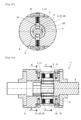
Fig 4 ] représente un deuxième mode de réalisation du dispositif anti-retour de transmission coaxiale de rotation. - La
Figure 1 illustre un dispositif anti-retour de transmission d'un mouvement de rotation 1. - Ce dispositif 1 est destiné à transmettre une rotation entre deux arbres en mettant en oeuvre une fonction anti-retour, c'est-à-dire une fonction empêchant une transmission de rotation depuis l'arbre de sortie vers l'arbre d'entrée.
- Le dispositif anti-retour 1 comporte les deux arbres d'entrée 2 et de sortie 3 agencés de manière coaxiale et un bâti 4 assurant le guidage en rotation des arbres 2, 3.
- Les arbres 2, 3 peuvent être insérés sur un système existant (non représenté), qui comporte par exemple un arbre piloté en rotation sur lequel on veut ajouter une fonction d'anti-retour en rotation et un arbre mené auxquels sont respectivement raccordés les arbres d'entrée et de sortie 2 et 3.
- Les arbres comportent des moyens de coopération mutuelle pour la transmission d'un mouvement de rotation axiale de l'un à l'autre. L'arbre d'entrée 2 est notamment destiné à piloter l'arbre de sortie 3.
- Par exemple, l'arbre d'entrée comporte une extrémité mâle 24 engagée dans une extrémité femelle 32 de l'arbre de sortie 3.
- Comme illustré sur la
Figure 2A , le bâti 4 permet le support et le guidage en rotation des arbres 2, 3, par exemple au moyen de paliers lisses ou de roulements. - Un élément de verrouillage 5 est inséré dans un conduit transversal 31 de l'arbre de sortie 3. L'élément de verrouillage 5 peut translater radialement à travers ledit conduit 31, entre une position radiale dite de verrouillage et une position radiale dite de déverrouillage.
- Dans la position de verrouillage illustrée sur les
figures 2A, 2B et2C , l'élément de verrouillage 5 est saillant hors du conduit 31. Il empêche alors une rotation de l'arbre de sortie 2 en butant contre le bâti 4. - Dans la position de déverrouillage illustrée sur les
figures 3A ,3B ,3C et4 , l'élément de verrouillage 5 est escamoté et ne bute pas contre le bâti, autorisant la rotation axiale de l'arbre de sortie 3. - Par exemple, le bâti comporte un passage 41 dans lequel l'élément de verrouillage 5 est escamoté dans la position de déverrouillage. Dans la position de verrouillage, le passage 41 coïncide avec le conduit 31 de l'arbre de sortie 3 et l'élément de verrouillage 5 peut alors translater radialement au travers dudit passage 41 de manière à s'escamoter et autoriser une rotation de l'arbre de sortie 2.
- L'arbre d'entrée 2 comporte en outre des moyens d'entraînement de l'arbre de sortie 3 et des moyens de commutation 21 radiale de l'élément de verrouillage 5 entre ses positions radiale de verrouillage et de déverrouillage par un mouvement de rotation dudit arbre d'entrée 2. En revanche, l'arbre de sortie ne dispose d'aucun moyen de commutation de l'élément de verrouillage 5.
- Un entraînement en rotation de l'arbre d'entrée 2 entraîne sensiblement simultanément un entraînement en rotation de l'arbre de sortie 3 et un passage en position déverrouillée de l'élément de verrouillage 5.
- En se référant aux
Figures 2B et3B , l'arbre d'entrée 2 comporte par exemple un épaulement 25 venant en butée contre un méplat 33 de l'arbre de sortie 3 pour mener en rotation l'arbre de sortie 3. L'atteinte de la butée par l'épaulement 25 lors d'une rotation de l'arbre d'entrée 2 coïncide angulairement avec la mise en position déverrouillée de l'élément de verrouillage 5 grâce aux moyens de commutation 21. - Par exemple, les moyens de commutation 21 de l'élément de verrouillage 5 comportent une came 22 ayant un profilé 23 adapté pour déplacer radialement l'élément de verrouillage 5 lors d'une rotation de l'arbre d'entrée 2.
- Avantageusement, la came 22 est prévue sur une extrémité mâle 24 de l'arbre d'entrée 2, ladite extrémité mâle 24 étant engagée dans une extrémité femelle 32 de l'arbre de sortie 3. La came 22, engagée dans l'arbre de sortie, repousse alors radialement l'élément de verrouillage 5 de l'intérieur du conduit 31 vers l'extérieur de l'arbre de sortie 3.
- Le profilé 23 est par exemple un polygone. Le nombre de sommets du polygone permet de multiplier le nombre de positions de déverrouillage du dispositif 1.
- Dans un premier mode de réalisation illustré en
Figures 2C et3C , le profilé 23 peut présenter une forme de losange. La position de verrouillage (Figure 2C ) est alors atteinte lorsque la came 22 repousse radialement l'élément de verrouillage 5 au minimum, par sa dimension minimale, à savoir la petite hauteur du losange 23, et la position de déverrouillage (Figure 3C ) est atteinte lorsque la came 22 repousse radialement l'élément de verrouillage 5 au maximum, par sa dimension maximale, à savoir la grande hauteur du losange 23. - Dans un deuxième mode de réalisation illustré en
Figure 4 , le profilé 23 peut présenter une section hexagonale. La position de déverrouillage telle qu'illustrée est alors atteinte lorsque la came 22 repousse radialement l'élément de verrouillage 5 par un sommet de l'hexagone 23. - Ainsi, dans le premier mode de réalisation, une rotation de l'arbre d'entrée 2 sur moins d'un quart de tour est nécessaire pour déverrouiller et entraîner en rotation l'arbre de sortie 3, tandis que dans le deuxième mode de réalisation, une rotation de vingt degrés d'angle suffit.
- Les moyens de commutation 21 de l'élément de verrouillage 5 peuvent en outre comporter une clavette de déverrouillage 6 interposée entre la came 22 et l'élément de verrouillage 5. La clavette 6 est alors liée en translation à travers le conduit 31 de l'arbre de sortie 3. Elle sert de repoussoir radial de l'élément de verrouillage 5 hors du conduit 31.
- En position de verrouillage (
Figure 2C ), la clavette 6 est située entre le conduit 31 et l'arbre de sortie 3 et ne déloge pas l'élément de verrouillage 5 du conduit 31. - En position de déverrouillage (
Figure 3C ), la clavette est entièrement logée dans le conduit 31 et déloge complètement l'élément de verrouillage 5 du conduit 31. La clavette 6 peut alors tourner autour de l'axe des arbres, solidairement à l'arbre de sortie 3 dont la rotation est autorisée. - La clavette 6 peut avoir une forme bombée, complémentaire du conduit 31, de manière à ne pas dépasser hors du conduit 31 en restant circonscrit dans le conduit 21 et à ne pas buter contre le bâti 4 dans la position de déverrouillage.
- En outre, le dispositif 1 peut comporter des moyens de rappel élastique en position de verrouillage 7 de l'élément de verrouillage 5, travaillant en compression pour pousser l'élément de verrouillage 5 vers l'axe des arbres 2, 3, à l'encontre de la came 22.
- Par exemple, les moyens de rappel élastique en position verrouillée 7 comportent un ressort 71 lié au bâti 4.
- Ainsi, depuis la position de déverrouillage (
Figures 3C et4 ), dès lors que la position angulaire de l'arbre de sortie 3 par rapport à l'arbre d'entrée 2 est telle que le conduit 21 est aligné avec le passage 41, les moyens de rappel 7 repoussent l'élément de verrouillage 5 contre la clavette 6 dans le conduit 21. La position verrouillée est alors enclenchée par le positionnement saillant de l'élément de verrouillage 5 entre le conduit 21 et le passage 41, toute possibilité de rotation de l'arbre de sortie 3 étant alors empêchée. - Ainsi, le dispositif permet que, dans la position de déverrouillage, toute transmission en rotation hétérocinétique entre les arbres d'entrée 2 et de sortie 3, c'est-à-dire toute transmission menée par l'arbre de sortie plutôt que par les moyens d'entraînement de l'arbre d'entrée 2, entraîne un alignement du conduit 21 et du passage 41 et donc un retour en position de verrouillage grâce aux moyens de rappel 7.
- On réalise ainsi un dispositif anti-retour grâce auquel un entraînement en rotation de l'arbre d'entrée 2 déverrouille les moyens de verrouillage 5 et transmet coaxialement le mouvement de rotation à l'arbre de sortie 3 mené par les moyens d'entraînement 25, 33, tandis qu'un entraînement en rotation de l'arbre de sortie 3 ne mène pas l'arbre d'entrée en rotation et déclenche un retour en position verrouillée du dispositif 1.
Claims (8)
- Dispositif anti-retour de transmission d'un mouvement de rotation (1) comportant deux arbres d'entrée (2) et de sortie (3) coaxiaux, un bâti (4) de guidage en rotation des arbres (2, 3), un élément de verrouillage (5) déplaçable en translation radiale à travers un conduit (31) de l'arbre de sortie (3) entre une position de verrouillage dans laquelle ledit élément de verrouillage (5) est saillant hors dudit conduit (31) de manière à empêcher une rotation de l'arbre de sortie (2) et une position radiale de déverrouillage dans laquelle l'élément de verrouillage (5) est escamoté de manière à autoriser la rotation axiale de l'arbre de sortie (3), l'arbre d'entrée (2) comportant des moyens de commutation de l'élément de verrouillage (21) entre ses positions de verrouillage et de déverrouillage,les moyens de commutation (21) de l'élément de verrouillage (5) comportant une came (22) ayant un profilé (23) adapté pour déplacer radialement l'élément de verrouillage (5) lors d'une rotation de l'arbre d'entrée (2),caractérisé en ce que l'arbre d'entrée (2) comprend un épaulement (25) venant en butée contre un méplat (33) de l'arbre de sortie (3) pour mener en rotation l'arbre de sortie (3), l'atteinte de la butée par l'épaulement (25) lors d'une rotation de l'arbre d'entrée (2) coïncidant angulairement avec la mise en position déverrouillée de l'élément de verrouillage (5) par la came (23).
- Dispositif selon la revendication 1, dans lequel la came (22) est pourvue sur une extrémité mâle (24) de l'arbre d'entrée (2), ladite extrémité mâle (24) étant engagée dans une extrémité femelle (32) de l'arbre de sortie (3).
- Dispositif selon l'une quelconque des revendications précédentes, dans lequel les moyens de commutation (21) de l'élément de verrouillage (5) comportent une clavette de déverrouillage (6) interposée entre la came (22) et ledit élément de verrouillage (5), ladite clavette (6) étant liée en translation à travers le conduit (31) de l'arbre de sortie (3).
- Dispositif selon la revendication 3, dans lequel la clavette de déverrouillage (6) est entièrement logée dans le conduit (31) de l'arbre de sortie (3) dans la position de déverrouillage.
- Dispositif selon l'une quelconque des revendications précédentes, comportant des moyens de rappel élastique en position de verrouillage (7) de l'élément de verrouillage (5), travaillant en compression pour pousser ledit élément de verrouillage (5) vers l'axe des arbres (2, 3) à l'encontre de la came (22) ou, le cas échéant, à l'encontre de la clavette de déverrouillage (6).
- Dispositif selon la revendication 5, dans lequel les moyens de rappel élastique en position verrouillée (7) comportent un ressort (71) lié au bâti (4).
- Dispositif selon l'une des revendications 5 et 6, dans lequel le bâti (4) comprend un passage (41) coïncidant avec le conduit de l'arbre de sortie (31) dans la position de verrouillage, l'élément de verrouillage (5) et la clavette de déverrouillage (6) pouvant translater radialement au travers dudit passage (41) dans la position de verrouillage.
- Dispositif selon l'une quelconque des revendications précédentes, dans lequel un entraînement en rotation de l'arbre de sortie (3) par l'arbre d'entrée (2) et un passage en position déverrouillée surviennent sensiblement simultanément après un entraînement en rotation dudit arbre d'entrée (2) sur moins d'un quart de tour.
Applications Claiming Priority (2)
| Application Number | Priority Date | Filing Date | Title |
|---|---|---|---|
| FR1909786A FR3100624B1 (fr) | 2019-09-05 | 2019-09-05 | Dispositif anti-retour de transmission de rotation |
| PCT/EP2020/074661 WO2021043934A1 (fr) | 2019-09-05 | 2020-09-03 | Dispositif anti-retour de transmission de rotation |
Publications (2)
| Publication Number | Publication Date |
|---|---|
| EP4025799A1 EP4025799A1 (fr) | 2022-07-13 |
| EP4025799B1 true EP4025799B1 (fr) | 2024-08-14 |
Family
ID=68211105
Family Applications (1)
| Application Number | Title | Priority Date | Filing Date |
|---|---|---|---|
| EP20764673.8A Active EP4025799B1 (fr) | 2019-09-05 | 2020-09-03 | Dispositif anti-retour de transmission de rotation |
Country Status (6)
| Country | Link |
|---|---|
| US (1) | US11982326B2 (fr) |
| EP (1) | EP4025799B1 (fr) |
| JP (1) | JP7635209B2 (fr) |
| ES (1) | ES2989731T3 (fr) |
| FR (1) | FR3100624B1 (fr) |
| WO (1) | WO2021043934A1 (fr) |
Family Cites Families (6)
| Publication number | Priority date | Publication date | Assignee | Title |
|---|---|---|---|---|
| US1845667A (en) * | 1927-11-30 | 1932-02-16 | Charles A Johnson | Clutch |
| SE328723B (fr) * | 1966-03-23 | 1970-09-21 | Naradi Narodni Podnik | |
| IT1227375B (it) * | 1988-11-22 | 1991-04-08 | Carraro Spa | Meccanismo differenziale per autoveicoli. |
| US20150107953A1 (en) * | 2013-10-23 | 2015-04-23 | Jeffrey M. Lucas | Eccentric Lock One Way Clutch |
| KR101611719B1 (ko) * | 2014-08-28 | 2016-04-14 | 주식회사 포스코 | 소재 이송장치 및 이를 포함하는 절단기 |
| JP2018035871A (ja) * | 2016-08-31 | 2018-03-08 | Ntn株式会社 | クラッチユニット |
-
2019
- 2019-09-05 FR FR1909786A patent/FR3100624B1/fr active Active
-
2020
- 2020-09-03 JP JP2022514976A patent/JP7635209B2/ja active Active
- 2020-09-03 ES ES20764673T patent/ES2989731T3/es active Active
- 2020-09-03 WO PCT/EP2020/074661 patent/WO2021043934A1/fr not_active Ceased
- 2020-09-03 US US17/640,064 patent/US11982326B2/en active Active
- 2020-09-03 EP EP20764673.8A patent/EP4025799B1/fr active Active
Also Published As
| Publication number | Publication date |
|---|---|
| WO2021043934A1 (fr) | 2021-03-11 |
| US20220341473A1 (en) | 2022-10-27 |
| US11982326B2 (en) | 2024-05-14 |
| JP2022547122A (ja) | 2022-11-10 |
| JP7635209B2 (ja) | 2025-03-05 |
| FR3100624B1 (fr) | 2021-10-08 |
| ES2989731T3 (es) | 2024-11-27 |
| FR3100624A1 (fr) | 2021-03-12 |
| EP4025799A1 (fr) | 2022-07-13 |
Similar Documents
| Publication | Publication Date | Title |
|---|---|---|
| EP0334704B1 (fr) | Attache rapide du type à baionnette perfectionnée | |
| EP2024219B1 (fr) | Systeme de verrouillage d'un premier arbre par rapport a un deuxieme arbre supprimant les jeux entre lesdits arbres | |
| EP2048425B1 (fr) | Elément femelle de raccord et raccord comprenant un tel élément femelle | |
| FR3023987B1 (fr) | Dispositif de couplage antivibration | |
| EP2863074B1 (fr) | Broches à billes à levier | |
| EP1862720A1 (fr) | Elément femelle de raccord et raccord rapide incorporant un tel élément | |
| CA2845667A1 (fr) | Systeme mecanique comprenant un dispositif de liaison entre une piece d'usure et son support, godet d'engin de travaux publics et procede de mise en oeuvre d'un tel systeme | |
| EP4025799B1 (fr) | Dispositif anti-retour de transmission de rotation | |
| EP0742403B1 (fr) | Raccord hydraulique étanche | |
| EP3877252A1 (fr) | Dispositif d'ouverture d'urgence d'une porte d'aéronef, à débrayage rotatif | |
| EP2173953B1 (fr) | Dispositif de liaison entre un verrou et une serrure de porte de vehicule automobile | |
| EP3282204B1 (fr) | Système de raccordement de connecteurs de deux unités de climatisation à position de verrouillage irréversible | |
| WO2013178962A2 (fr) | Dispositif et procédé d'emmanchement de deux raccords au bout de deux conduits, notamment dans un aéronef | |
| EP2236713B1 (fr) | Dispositif de verrouillage quart de tour à deux éléments | |
| EP1378385A1 (fr) | Embout pour dispositif d'enroulement d'un élément enroulable tel que bâche ou similaire, notamment d'un véhicule | |
| FR3095480A3 (fr) | Liaison entre deux éléments montés articulés l’un à l’autre. | |
| FR2802233A1 (fr) | Barillet de surete muni d'un moyen anti-vibreur | |
| FR2778214A1 (fr) | Dispositif ecrou de mise en place rapide, a deux demi-ecrous et agencement de blocage notamment pour coffrage de beton, utilisant un tel dispositif ecrou | |
| FR2802234A1 (fr) | Barillet de surete muni d'un moyen anti-crochetage | |
| FR2775716A1 (fr) | Cylindre de surete a barillet double | |
| FR3114113A1 (fr) | dispositif de rapprochement et d’assemblage de structures pré-percées et ensemble comprenant au moins un tel dispositif de rapprochement et d’assemblage | |
| EP2594817B1 (fr) | Dispositif de positionnement axial d'une bielle par rapport à son arbre d'entraînement, et dispositif d'interverrouillage de porte dans une cellule comportant un tel dispositif | |
| EP0747653B1 (fr) | Ensemble comprenant un élément, une tige mobile en translation axiale par rapport à cet élément et une pièce de blocage | |
| FR3052521B1 (fr) | Dispositif de rattrapage de jeu de pignon de systeme de distribution | |
| EP0869236B1 (fr) | Cylindre de sûrete manoeuvrable d'un côté quand une clef est en place de l'autre côté |
Legal Events
| Date | Code | Title | Description |
|---|---|---|---|
| STAA | Information on the status of an ep patent application or granted ep patent |
Free format text: STATUS: UNKNOWN |
|
| STAA | Information on the status of an ep patent application or granted ep patent |
Free format text: STATUS: THE INTERNATIONAL PUBLICATION HAS BEEN MADE |
|
| PUAI | Public reference made under article 153(3) epc to a published international application that has entered the european phase |
Free format text: ORIGINAL CODE: 0009012 |
|
| STAA | Information on the status of an ep patent application or granted ep patent |
Free format text: STATUS: REQUEST FOR EXAMINATION WAS MADE |
|
| 17P | Request for examination filed |
Effective date: 20220309 |
|
| AK | Designated contracting states |
Kind code of ref document: A1 Designated state(s): AL AT BE BG CH CY CZ DE DK EE ES FI FR GB GR HR HU IE IS IT LI LT LU LV MC MK MT NL NO PL PT RO RS SE SI SK SM TR |
|
| DAV | Request for validation of the european patent (deleted) | ||
| DAX | Request for extension of the european patent (deleted) | ||
| STAA | Information on the status of an ep patent application or granted ep patent |
Free format text: STATUS: EXAMINATION IS IN PROGRESS |
|
| 17Q | First examination report despatched |
Effective date: 20240131 |
|
| GRAP | Despatch of communication of intention to grant a patent |
Free format text: ORIGINAL CODE: EPIDOSNIGR1 |
|
| STAA | Information on the status of an ep patent application or granted ep patent |
Free format text: STATUS: GRANT OF PATENT IS INTENDED |
|
| INTG | Intention to grant announced |
Effective date: 20240321 |
|
| RAP1 | Party data changed (applicant data changed or rights of an application transferred) |
Owner name: SAFRAN ELECTRONICS & DEFENSE |
|
| GRAS | Grant fee paid |
Free format text: ORIGINAL CODE: EPIDOSNIGR3 |
|
| GRAA | (expected) grant |
Free format text: ORIGINAL CODE: 0009210 |
|
| STAA | Information on the status of an ep patent application or granted ep patent |
Free format text: STATUS: THE PATENT HAS BEEN GRANTED |
|
| AK | Designated contracting states |
Kind code of ref document: B1 Designated state(s): AL AT BE BG CH CY CZ DE DK EE ES FI FR GB GR HR HU IE IS IT LI LT LU LV MC MK MT NL NO PL PT RO RS SE SI SK SM TR |
|
| REG | Reference to a national code |
Ref country code: GB Ref legal event code: FG4D Free format text: NOT ENGLISH |
|
| REG | Reference to a national code |
Ref country code: CH Ref legal event code: EP |
|
| REG | Reference to a national code |
Ref country code: DE Ref legal event code: R096 Ref document number: 602020035809 Country of ref document: DE |
|
| REG | Reference to a national code |
Ref country code: IE Ref legal event code: FG4D Free format text: LANGUAGE OF EP DOCUMENT: FRENCH |
|
| REG | Reference to a national code |
Ref country code: ES Ref legal event code: FG2A Ref document number: 2989731 Country of ref document: ES Kind code of ref document: T3 Effective date: 20241127 |
|
| REG | Reference to a national code |
Ref country code: LT Ref legal event code: MG9D |
|
| REG | Reference to a national code |
Ref country code: NL Ref legal event code: MP Effective date: 20240814 |
|
| PG25 | Lapsed in a contracting state [announced via postgrant information from national office to epo] |
Ref country code: NO Free format text: LAPSE BECAUSE OF FAILURE TO SUBMIT A TRANSLATION OF THE DESCRIPTION OR TO PAY THE FEE WITHIN THE PRESCRIBED TIME-LIMIT Effective date: 20241114 |
|
| REG | Reference to a national code |
Ref country code: AT Ref legal event code: MK05 Ref document number: 1713553 Country of ref document: AT Kind code of ref document: T Effective date: 20240814 |
|
| PG25 | Lapsed in a contracting state [announced via postgrant information from national office to epo] |
Ref country code: NL Free format text: LAPSE BECAUSE OF FAILURE TO SUBMIT A TRANSLATION OF THE DESCRIPTION OR TO PAY THE FEE WITHIN THE PRESCRIBED TIME-LIMIT Effective date: 20240814 Ref country code: PT Free format text: LAPSE BECAUSE OF FAILURE TO SUBMIT A TRANSLATION OF THE DESCRIPTION OR TO PAY THE FEE WITHIN THE PRESCRIBED TIME-LIMIT Effective date: 20241216 Ref country code: FI Free format text: LAPSE BECAUSE OF FAILURE TO SUBMIT A TRANSLATION OF THE DESCRIPTION OR TO PAY THE FEE WITHIN THE PRESCRIBED TIME-LIMIT Effective date: 20240814 Ref country code: PL Free format text: LAPSE BECAUSE OF FAILURE TO SUBMIT A TRANSLATION OF THE DESCRIPTION OR TO PAY THE FEE WITHIN THE PRESCRIBED TIME-LIMIT Effective date: 20240814 Ref country code: GR Free format text: LAPSE BECAUSE OF FAILURE TO SUBMIT A TRANSLATION OF THE DESCRIPTION OR TO PAY THE FEE WITHIN THE PRESCRIBED TIME-LIMIT Effective date: 20241115 |
|
| PG25 | Lapsed in a contracting state [announced via postgrant information from national office to epo] |
Ref country code: BG Free format text: LAPSE BECAUSE OF FAILURE TO SUBMIT A TRANSLATION OF THE DESCRIPTION OR TO PAY THE FEE WITHIN THE PRESCRIBED TIME-LIMIT Effective date: 20240814 |
|
| PG25 | Lapsed in a contracting state [announced via postgrant information from national office to epo] |
Ref country code: LV Free format text: LAPSE BECAUSE OF FAILURE TO SUBMIT A TRANSLATION OF THE DESCRIPTION OR TO PAY THE FEE WITHIN THE PRESCRIBED TIME-LIMIT Effective date: 20240814 |
|
| PG25 | Lapsed in a contracting state [announced via postgrant information from national office to epo] |
Ref country code: AT Free format text: LAPSE BECAUSE OF FAILURE TO SUBMIT A TRANSLATION OF THE DESCRIPTION OR TO PAY THE FEE WITHIN THE PRESCRIBED TIME-LIMIT Effective date: 20240814 Ref country code: IS Free format text: LAPSE BECAUSE OF FAILURE TO SUBMIT A TRANSLATION OF THE DESCRIPTION OR TO PAY THE FEE WITHIN THE PRESCRIBED TIME-LIMIT Effective date: 20241214 |
|
| PG25 | Lapsed in a contracting state [announced via postgrant information from national office to epo] |
Ref country code: HR Free format text: LAPSE BECAUSE OF FAILURE TO SUBMIT A TRANSLATION OF THE DESCRIPTION OR TO PAY THE FEE WITHIN THE PRESCRIBED TIME-LIMIT Effective date: 20240814 |
|
| PG25 | Lapsed in a contracting state [announced via postgrant information from national office to epo] |
Ref country code: RS Free format text: LAPSE BECAUSE OF FAILURE TO SUBMIT A TRANSLATION OF THE DESCRIPTION OR TO PAY THE FEE WITHIN THE PRESCRIBED TIME-LIMIT Effective date: 20241114 |
|
| PG25 | Lapsed in a contracting state [announced via postgrant information from national office to epo] |
Ref country code: RS Free format text: LAPSE BECAUSE OF FAILURE TO SUBMIT A TRANSLATION OF THE DESCRIPTION OR TO PAY THE FEE WITHIN THE PRESCRIBED TIME-LIMIT Effective date: 20241114 Ref country code: PT Free format text: LAPSE BECAUSE OF FAILURE TO SUBMIT A TRANSLATION OF THE DESCRIPTION OR TO PAY THE FEE WITHIN THE PRESCRIBED TIME-LIMIT Effective date: 20241216 Ref country code: PL Free format text: LAPSE BECAUSE OF FAILURE TO SUBMIT A TRANSLATION OF THE DESCRIPTION OR TO PAY THE FEE WITHIN THE PRESCRIBED TIME-LIMIT Effective date: 20240814 Ref country code: NO Free format text: LAPSE BECAUSE OF FAILURE TO SUBMIT A TRANSLATION OF THE DESCRIPTION OR TO PAY THE FEE WITHIN THE PRESCRIBED TIME-LIMIT Effective date: 20241114 Ref country code: NL Free format text: LAPSE BECAUSE OF FAILURE TO SUBMIT A TRANSLATION OF THE DESCRIPTION OR TO PAY THE FEE WITHIN THE PRESCRIBED TIME-LIMIT Effective date: 20240814 Ref country code: LV Free format text: LAPSE BECAUSE OF FAILURE TO SUBMIT A TRANSLATION OF THE DESCRIPTION OR TO PAY THE FEE WITHIN THE PRESCRIBED TIME-LIMIT Effective date: 20240814 Ref country code: IS Free format text: LAPSE BECAUSE OF FAILURE TO SUBMIT A TRANSLATION OF THE DESCRIPTION OR TO PAY THE FEE WITHIN THE PRESCRIBED TIME-LIMIT Effective date: 20241214 Ref country code: HR Free format text: LAPSE BECAUSE OF FAILURE TO SUBMIT A TRANSLATION OF THE DESCRIPTION OR TO PAY THE FEE WITHIN THE PRESCRIBED TIME-LIMIT Effective date: 20240814 Ref country code: GR Free format text: LAPSE BECAUSE OF FAILURE TO SUBMIT A TRANSLATION OF THE DESCRIPTION OR TO PAY THE FEE WITHIN THE PRESCRIBED TIME-LIMIT Effective date: 20241115 Ref country code: FI Free format text: LAPSE BECAUSE OF FAILURE TO SUBMIT A TRANSLATION OF THE DESCRIPTION OR TO PAY THE FEE WITHIN THE PRESCRIBED TIME-LIMIT Effective date: 20240814 Ref country code: BG Free format text: LAPSE BECAUSE OF FAILURE TO SUBMIT A TRANSLATION OF THE DESCRIPTION OR TO PAY THE FEE WITHIN THE PRESCRIBED TIME-LIMIT Effective date: 20240814 Ref country code: AT Free format text: LAPSE BECAUSE OF FAILURE TO SUBMIT A TRANSLATION OF THE DESCRIPTION OR TO PAY THE FEE WITHIN THE PRESCRIBED TIME-LIMIT Effective date: 20240814 |
|
| PG25 | Lapsed in a contracting state [announced via postgrant information from national office to epo] |
Ref country code: DK Free format text: LAPSE BECAUSE OF FAILURE TO SUBMIT A TRANSLATION OF THE DESCRIPTION OR TO PAY THE FEE WITHIN THE PRESCRIBED TIME-LIMIT Effective date: 20240814 Ref country code: SM Free format text: LAPSE BECAUSE OF FAILURE TO SUBMIT A TRANSLATION OF THE DESCRIPTION OR TO PAY THE FEE WITHIN THE PRESCRIBED TIME-LIMIT Effective date: 20240814 Ref country code: RO Free format text: LAPSE BECAUSE OF FAILURE TO SUBMIT A TRANSLATION OF THE DESCRIPTION OR TO PAY THE FEE WITHIN THE PRESCRIBED TIME-LIMIT Effective date: 20240814 |
|
| PG25 | Lapsed in a contracting state [announced via postgrant information from national office to epo] |
Ref country code: EE Free format text: LAPSE BECAUSE OF FAILURE TO SUBMIT A TRANSLATION OF THE DESCRIPTION OR TO PAY THE FEE WITHIN THE PRESCRIBED TIME-LIMIT Effective date: 20240814 |
|
| PG25 | Lapsed in a contracting state [announced via postgrant information from national office to epo] |
Ref country code: CZ Free format text: LAPSE BECAUSE OF FAILURE TO SUBMIT A TRANSLATION OF THE DESCRIPTION OR TO PAY THE FEE WITHIN THE PRESCRIBED TIME-LIMIT Effective date: 20240814 |
|
| PG25 | Lapsed in a contracting state [announced via postgrant information from national office to epo] |
Ref country code: SK Free format text: LAPSE BECAUSE OF FAILURE TO SUBMIT A TRANSLATION OF THE DESCRIPTION OR TO PAY THE FEE WITHIN THE PRESCRIBED TIME-LIMIT Effective date: 20240814 |
|
| REG | Reference to a national code |
Ref country code: CH Ref legal event code: PL |
|
| REG | Reference to a national code |
Ref country code: DE Ref legal event code: R097 Ref document number: 602020035809 Country of ref document: DE |
|
| PG25 | Lapsed in a contracting state [announced via postgrant information from national office to epo] |
Ref country code: LU Free format text: LAPSE BECAUSE OF NON-PAYMENT OF DUE FEES Effective date: 20240903 |
|
| PLBE | No opposition filed within time limit |
Free format text: ORIGINAL CODE: 0009261 |
|
| STAA | Information on the status of an ep patent application or granted ep patent |
Free format text: STATUS: NO OPPOSITION FILED WITHIN TIME LIMIT |
|
| PG25 | Lapsed in a contracting state [announced via postgrant information from national office to epo] |
Ref country code: MC Free format text: LAPSE BECAUSE OF FAILURE TO SUBMIT A TRANSLATION OF THE DESCRIPTION OR TO PAY THE FEE WITHIN THE PRESCRIBED TIME-LIMIT Effective date: 20240814 |
|
| REG | Reference to a national code |
Ref country code: BE Ref legal event code: MM Effective date: 20240930 |
|
| PG25 | Lapsed in a contracting state [announced via postgrant information from national office to epo] |
Ref country code: BE Free format text: LAPSE BECAUSE OF NON-PAYMENT OF DUE FEES Effective date: 20240930 |
|
| 26N | No opposition filed |
Effective date: 20250515 |
|
| PG25 | Lapsed in a contracting state [announced via postgrant information from national office to epo] |
Ref country code: CH Free format text: LAPSE BECAUSE OF NON-PAYMENT OF DUE FEES Effective date: 20240930 |
|
| PG25 | Lapsed in a contracting state [announced via postgrant information from national office to epo] |
Ref country code: SE Free format text: LAPSE BECAUSE OF FAILURE TO SUBMIT A TRANSLATION OF THE DESCRIPTION OR TO PAY THE FEE WITHIN THE PRESCRIBED TIME-LIMIT Effective date: 20240814 |
|
| PGFP | Annual fee paid to national office [announced via postgrant information from national office to epo] |
Ref country code: DE Payment date: 20250919 Year of fee payment: 6 |
|
| PGFP | Annual fee paid to national office [announced via postgrant information from national office to epo] |
Ref country code: GB Payment date: 20250923 Year of fee payment: 6 |
|
| PGFP | Annual fee paid to national office [announced via postgrant information from national office to epo] |
Ref country code: FR Payment date: 20250923 Year of fee payment: 6 |
|
| PGFP | Annual fee paid to national office [announced via postgrant information from national office to epo] |
Ref country code: IE Payment date: 20250919 Year of fee payment: 6 |
|
| PGFP | Annual fee paid to national office [announced via postgrant information from national office to epo] |
Ref country code: IT Payment date: 20250930 Year of fee payment: 6 |
|
| PG25 | Lapsed in a contracting state [announced via postgrant information from national office to epo] |
Ref country code: CY Free format text: LAPSE BECAUSE OF FAILURE TO SUBMIT A TRANSLATION OF THE DESCRIPTION OR TO PAY THE FEE WITHIN THE PRESCRIBED TIME-LIMIT; INVALID AB INITIO Effective date: 20200903 |
|
| PGFP | Annual fee paid to national office [announced via postgrant information from national office to epo] |
Ref country code: ES Payment date: 20251020 Year of fee payment: 6 |
|
| PG25 | Lapsed in a contracting state [announced via postgrant information from national office to epo] |
Ref country code: HU Free format text: LAPSE BECAUSE OF FAILURE TO SUBMIT A TRANSLATION OF THE DESCRIPTION OR TO PAY THE FEE WITHIN THE PRESCRIBED TIME-LIMIT; INVALID AB INITIO Effective date: 20200903 |