EP4025825B1 - Griffanordnung für einen tragbaren druckgaszylinder - Google Patents
Griffanordnung für einen tragbaren druckgaszylinder Download PDFInfo
- Publication number
- EP4025825B1 EP4025825B1 EP20730805.7A EP20730805A EP4025825B1 EP 4025825 B1 EP4025825 B1 EP 4025825B1 EP 20730805 A EP20730805 A EP 20730805A EP 4025825 B1 EP4025825 B1 EP 4025825B1
- Authority
- EP
- European Patent Office
- Prior art keywords
- circumferentially spaced
- handle
- shroud
- fingers
- gas cylinder
- Prior art date
- Legal status (The legal status is an assumption and is not a legal conclusion. Google has not performed a legal analysis and makes no representation as to the accuracy of the status listed.)
- Active
Links
Images










Classifications
-
- F—MECHANICAL ENGINEERING; LIGHTING; HEATING; WEAPONS; BLASTING
- F17—STORING OR DISTRIBUTING GASES OR LIQUIDS
- F17C—VESSELS FOR CONTAINING OR STORING COMPRESSED, LIQUEFIED OR SOLIDIFIED GASES; FIXED-CAPACITY GAS-HOLDERS; FILLING VESSELS WITH, OR DISCHARGING FROM VESSELS, COMPRESSED, LIQUEFIED, OR SOLIDIFIED GASES
- F17C13/00—Details of vessels or of the filling or discharging of vessels
- F17C13/08—Mounting arrangements for vessels
-
- F—MECHANICAL ENGINEERING; LIGHTING; HEATING; WEAPONS; BLASTING
- F17—STORING OR DISTRIBUTING GASES OR LIQUIDS
- F17C—VESSELS FOR CONTAINING OR STORING COMPRESSED, LIQUEFIED OR SOLIDIFIED GASES; FIXED-CAPACITY GAS-HOLDERS; FILLING VESSELS WITH, OR DISCHARGING FROM VESSELS, COMPRESSED, LIQUEFIED, OR SOLIDIFIED GASES
- F17C13/00—Details of vessels or of the filling or discharging of vessels
- F17C13/08—Mounting arrangements for vessels
- F17C13/084—Mounting arrangements for vessels for small-sized storage vessels, e.g. compressed gas cylinders or bottles, disposable gas vessels, vessels adapted for automotive use
-
- B—PERFORMING OPERATIONS; TRANSPORTING
- B65—CONVEYING; PACKING; STORING; HANDLING THIN OR FILAMENTARY MATERIAL
- B65D—CONTAINERS FOR STORAGE OR TRANSPORT OF ARTICLES OR MATERIALS, e.g. BAGS, BARRELS, BOTTLES, BOXES, CANS, CARTONS, CRATES, DRUMS, JARS, TANKS, HOPPERS, FORWARDING CONTAINERS; ACCESSORIES, CLOSURES, OR FITTINGS THEREFOR; PACKAGING ELEMENTS; PACKAGES
- B65D25/00—Details of other kinds or types of rigid or semi-rigid containers
- B65D25/28—Handles
- B65D25/30—Hand holes
-
- B—PERFORMING OPERATIONS; TRANSPORTING
- B65—CONVEYING; PACKING; STORING; HANDLING THIN OR FILAMENTARY MATERIAL
- B65D—CONTAINERS FOR STORAGE OR TRANSPORT OF ARTICLES OR MATERIALS, e.g. BAGS, BARRELS, BOTTLES, BOXES, CANS, CARTONS, CRATES, DRUMS, JARS, TANKS, HOPPERS, FORWARDING CONTAINERS; ACCESSORIES, CLOSURES, OR FITTINGS THEREFOR; PACKAGING ELEMENTS; PACKAGES
- B65D25/00—Details of other kinds or types of rigid or semi-rigid containers
- B65D25/28—Handles
- B65D25/2802—Handles fixed, i.e. non-swingable, handles
- B65D25/2826—Handles fixed, i.e. non-swingable, handles provided on a local area of the upper (top) wall, e.g. U-shaped
-
- F—MECHANICAL ENGINEERING; LIGHTING; HEATING; WEAPONS; BLASTING
- F17—STORING OR DISTRIBUTING GASES OR LIQUIDS
- F17C—VESSELS FOR CONTAINING OR STORING COMPRESSED, LIQUEFIED OR SOLIDIFIED GASES; FIXED-CAPACITY GAS-HOLDERS; FILLING VESSELS WITH, OR DISCHARGING FROM VESSELS, COMPRESSED, LIQUEFIED, OR SOLIDIFIED GASES
- F17C2201/00—Vessel construction, in particular geometry, arrangement or size
- F17C2201/01—Shape
- F17C2201/0104—Shape cylindrical
- F17C2201/0109—Shape cylindrical with exteriorly curved end-piece
-
- F—MECHANICAL ENGINEERING; LIGHTING; HEATING; WEAPONS; BLASTING
- F17—STORING OR DISTRIBUTING GASES OR LIQUIDS
- F17C—VESSELS FOR CONTAINING OR STORING COMPRESSED, LIQUEFIED OR SOLIDIFIED GASES; FIXED-CAPACITY GAS-HOLDERS; FILLING VESSELS WITH, OR DISCHARGING FROM VESSELS, COMPRESSED, LIQUEFIED, OR SOLIDIFIED GASES
- F17C2201/00—Vessel construction, in particular geometry, arrangement or size
- F17C2201/01—Shape
- F17C2201/0104—Shape cylindrical
- F17C2201/0119—Shape cylindrical with flat end-piece
-
- F—MECHANICAL ENGINEERING; LIGHTING; HEATING; WEAPONS; BLASTING
- F17—STORING OR DISTRIBUTING GASES OR LIQUIDS
- F17C—VESSELS FOR CONTAINING OR STORING COMPRESSED, LIQUEFIED OR SOLIDIFIED GASES; FIXED-CAPACITY GAS-HOLDERS; FILLING VESSELS WITH, OR DISCHARGING FROM VESSELS, COMPRESSED, LIQUEFIED, OR SOLIDIFIED GASES
- F17C2201/00—Vessel construction, in particular geometry, arrangement or size
- F17C2201/03—Orientation
- F17C2201/032—Orientation with substantially vertical main axis
-
- F—MECHANICAL ENGINEERING; LIGHTING; HEATING; WEAPONS; BLASTING
- F17—STORING OR DISTRIBUTING GASES OR LIQUIDS
- F17C—VESSELS FOR CONTAINING OR STORING COMPRESSED, LIQUEFIED OR SOLIDIFIED GASES; FIXED-CAPACITY GAS-HOLDERS; FILLING VESSELS WITH, OR DISCHARGING FROM VESSELS, COMPRESSED, LIQUEFIED, OR SOLIDIFIED GASES
- F17C2201/00—Vessel construction, in particular geometry, arrangement or size
- F17C2201/05—Size
- F17C2201/056—Small (<1 m3)
-
- F—MECHANICAL ENGINEERING; LIGHTING; HEATING; WEAPONS; BLASTING
- F17—STORING OR DISTRIBUTING GASES OR LIQUIDS
- F17C—VESSELS FOR CONTAINING OR STORING COMPRESSED, LIQUEFIED OR SOLIDIFIED GASES; FIXED-CAPACITY GAS-HOLDERS; FILLING VESSELS WITH, OR DISCHARGING FROM VESSELS, COMPRESSED, LIQUEFIED, OR SOLIDIFIED GASES
- F17C2201/00—Vessel construction, in particular geometry, arrangement or size
- F17C2201/05—Size
- F17C2201/058—Size portable (<30 l)
-
- F—MECHANICAL ENGINEERING; LIGHTING; HEATING; WEAPONS; BLASTING
- F17—STORING OR DISTRIBUTING GASES OR LIQUIDS
- F17C—VESSELS FOR CONTAINING OR STORING COMPRESSED, LIQUEFIED OR SOLIDIFIED GASES; FIXED-CAPACITY GAS-HOLDERS; FILLING VESSELS WITH, OR DISCHARGING FROM VESSELS, COMPRESSED, LIQUEFIED, OR SOLIDIFIED GASES
- F17C2203/00—Vessel construction, in particular walls or details thereof
- F17C2203/06—Materials for walls or layers thereof; Properties or structures of walls or their materials
- F17C2203/0634—Materials for walls or layers thereof
- F17C2203/0636—Metals
-
- F—MECHANICAL ENGINEERING; LIGHTING; HEATING; WEAPONS; BLASTING
- F17—STORING OR DISTRIBUTING GASES OR LIQUIDS
- F17C—VESSELS FOR CONTAINING OR STORING COMPRESSED, LIQUEFIED OR SOLIDIFIED GASES; FIXED-CAPACITY GAS-HOLDERS; FILLING VESSELS WITH, OR DISCHARGING FROM VESSELS, COMPRESSED, LIQUEFIED, OR SOLIDIFIED GASES
- F17C2203/00—Vessel construction, in particular walls or details thereof
- F17C2203/06—Materials for walls or layers thereof; Properties or structures of walls or their materials
- F17C2203/0634—Materials for walls or layers thereof
- F17C2203/0636—Metals
- F17C2203/0639—Steels
-
- F—MECHANICAL ENGINEERING; LIGHTING; HEATING; WEAPONS; BLASTING
- F17—STORING OR DISTRIBUTING GASES OR LIQUIDS
- F17C—VESSELS FOR CONTAINING OR STORING COMPRESSED, LIQUEFIED OR SOLIDIFIED GASES; FIXED-CAPACITY GAS-HOLDERS; FILLING VESSELS WITH, OR DISCHARGING FROM VESSELS, COMPRESSED, LIQUEFIED, OR SOLIDIFIED GASES
- F17C2203/00—Vessel construction, in particular walls or details thereof
- F17C2203/06—Materials for walls or layers thereof; Properties or structures of walls or their materials
- F17C2203/0634—Materials for walls or layers thereof
- F17C2203/0658—Synthetics
- F17C2203/066—Plastics
-
- F—MECHANICAL ENGINEERING; LIGHTING; HEATING; WEAPONS; BLASTING
- F17—STORING OR DISTRIBUTING GASES OR LIQUIDS
- F17C—VESSELS FOR CONTAINING OR STORING COMPRESSED, LIQUEFIED OR SOLIDIFIED GASES; FIXED-CAPACITY GAS-HOLDERS; FILLING VESSELS WITH, OR DISCHARGING FROM VESSELS, COMPRESSED, LIQUEFIED, OR SOLIDIFIED GASES
- F17C2205/00—Vessel construction, in particular mounting arrangements, attachments or identifications means
- F17C2205/01—Mounting arrangements
- F17C2205/0103—Exterior arrangements
- F17C2205/0115—Dismountable protective hulls
-
- F—MECHANICAL ENGINEERING; LIGHTING; HEATING; WEAPONS; BLASTING
- F17—STORING OR DISTRIBUTING GASES OR LIQUIDS
- F17C—VESSELS FOR CONTAINING OR STORING COMPRESSED, LIQUEFIED OR SOLIDIFIED GASES; FIXED-CAPACITY GAS-HOLDERS; FILLING VESSELS WITH, OR DISCHARGING FROM VESSELS, COMPRESSED, LIQUEFIED, OR SOLIDIFIED GASES
- F17C2205/00—Vessel construction, in particular mounting arrangements, attachments or identifications means
- F17C2205/01—Mounting arrangements
- F17C2205/0153—Details of mounting arrangements
- F17C2205/0157—Details of mounting arrangements for transport
- F17C2205/0165—Details of mounting arrangements for transport with handgrip
-
- F—MECHANICAL ENGINEERING; LIGHTING; HEATING; WEAPONS; BLASTING
- F17—STORING OR DISTRIBUTING GASES OR LIQUIDS
- F17C—VESSELS FOR CONTAINING OR STORING COMPRESSED, LIQUEFIED OR SOLIDIFIED GASES; FIXED-CAPACITY GAS-HOLDERS; FILLING VESSELS WITH, OR DISCHARGING FROM VESSELS, COMPRESSED, LIQUEFIED, OR SOLIDIFIED GASES
- F17C2205/00—Vessel construction, in particular mounting arrangements, attachments or identifications means
- F17C2205/01—Mounting arrangements
- F17C2205/0153—Details of mounting arrangements
- F17C2205/018—Supporting feet
-
- F—MECHANICAL ENGINEERING; LIGHTING; HEATING; WEAPONS; BLASTING
- F17—STORING OR DISTRIBUTING GASES OR LIQUIDS
- F17C—VESSELS FOR CONTAINING OR STORING COMPRESSED, LIQUEFIED OR SOLIDIFIED GASES; FIXED-CAPACITY GAS-HOLDERS; FILLING VESSELS WITH, OR DISCHARGING FROM VESSELS, COMPRESSED, LIQUEFIED, OR SOLIDIFIED GASES
- F17C2205/00—Vessel construction, in particular mounting arrangements, attachments or identifications means
- F17C2205/03—Fluid connections, filters, valves, closure means or other attachments
- F17C2205/0302—Fittings, valves, filters, or components in connection with the gas storage device
- F17C2205/0308—Protective caps
-
- F—MECHANICAL ENGINEERING; LIGHTING; HEATING; WEAPONS; BLASTING
- F17—STORING OR DISTRIBUTING GASES OR LIQUIDS
- F17C—VESSELS FOR CONTAINING OR STORING COMPRESSED, LIQUEFIED OR SOLIDIFIED GASES; FIXED-CAPACITY GAS-HOLDERS; FILLING VESSELS WITH, OR DISCHARGING FROM VESSELS, COMPRESSED, LIQUEFIED, OR SOLIDIFIED GASES
- F17C2205/00—Vessel construction, in particular mounting arrangements, attachments or identifications means
- F17C2205/03—Fluid connections, filters, valves, closure means or other attachments
- F17C2205/0302—Fittings, valves, filters, or components in connection with the gas storage device
- F17C2205/0323—Valves
-
- F—MECHANICAL ENGINEERING; LIGHTING; HEATING; WEAPONS; BLASTING
- F17—STORING OR DISTRIBUTING GASES OR LIQUIDS
- F17C—VESSELS FOR CONTAINING OR STORING COMPRESSED, LIQUEFIED OR SOLIDIFIED GASES; FIXED-CAPACITY GAS-HOLDERS; FILLING VESSELS WITH, OR DISCHARGING FROM VESSELS, COMPRESSED, LIQUEFIED, OR SOLIDIFIED GASES
- F17C2205/00—Vessel construction, in particular mounting arrangements, attachments or identifications means
- F17C2205/05—Vessel or content identifications, e.g. labels
- F17C2205/051—Vessel or content identifications, e.g. labels by coating
-
- F—MECHANICAL ENGINEERING; LIGHTING; HEATING; WEAPONS; BLASTING
- F17—STORING OR DISTRIBUTING GASES OR LIQUIDS
- F17C—VESSELS FOR CONTAINING OR STORING COMPRESSED, LIQUEFIED OR SOLIDIFIED GASES; FIXED-CAPACITY GAS-HOLDERS; FILLING VESSELS WITH, OR DISCHARGING FROM VESSELS, COMPRESSED, LIQUEFIED, OR SOLIDIFIED GASES
- F17C2221/00—Handled fluid, in particular type of fluid
- F17C2221/03—Mixtures
- F17C2221/032—Hydrocarbons
- F17C2221/035—Propane butane, e.g. LPG, GPL
-
- F—MECHANICAL ENGINEERING; LIGHTING; HEATING; WEAPONS; BLASTING
- F17—STORING OR DISTRIBUTING GASES OR LIQUIDS
- F17C—VESSELS FOR CONTAINING OR STORING COMPRESSED, LIQUEFIED OR SOLIDIFIED GASES; FIXED-CAPACITY GAS-HOLDERS; FILLING VESSELS WITH, OR DISCHARGING FROM VESSELS, COMPRESSED, LIQUEFIED, OR SOLIDIFIED GASES
- F17C2223/00—Handled fluid before transfer, i.e. state of fluid when stored in the vessel or before transfer from the vessel
- F17C2223/01—Handled fluid before transfer, i.e. state of fluid when stored in the vessel or before transfer from the vessel characterised by the phase
- F17C2223/0107—Single phase
- F17C2223/0123—Single phase gaseous, e.g. CNG, GNC
-
- F—MECHANICAL ENGINEERING; LIGHTING; HEATING; WEAPONS; BLASTING
- F17—STORING OR DISTRIBUTING GASES OR LIQUIDS
- F17C—VESSELS FOR CONTAINING OR STORING COMPRESSED, LIQUEFIED OR SOLIDIFIED GASES; FIXED-CAPACITY GAS-HOLDERS; FILLING VESSELS WITH, OR DISCHARGING FROM VESSELS, COMPRESSED, LIQUEFIED, OR SOLIDIFIED GASES
- F17C2223/00—Handled fluid before transfer, i.e. state of fluid when stored in the vessel or before transfer from the vessel
- F17C2223/01—Handled fluid before transfer, i.e. state of fluid when stored in the vessel or before transfer from the vessel characterised by the phase
- F17C2223/0146—Two-phase
- F17C2223/0153—Liquefied gas, e.g. LPG, GPL
-
- F—MECHANICAL ENGINEERING; LIGHTING; HEATING; WEAPONS; BLASTING
- F17—STORING OR DISTRIBUTING GASES OR LIQUIDS
- F17C—VESSELS FOR CONTAINING OR STORING COMPRESSED, LIQUEFIED OR SOLIDIFIED GASES; FIXED-CAPACITY GAS-HOLDERS; FILLING VESSELS WITH, OR DISCHARGING FROM VESSELS, COMPRESSED, LIQUEFIED, OR SOLIDIFIED GASES
- F17C2223/00—Handled fluid before transfer, i.e. state of fluid when stored in the vessel or before transfer from the vessel
- F17C2223/03—Handled fluid before transfer, i.e. state of fluid when stored in the vessel or before transfer from the vessel characterised by the pressure level
- F17C2223/033—Small pressure, e.g. for liquefied gas
-
- F—MECHANICAL ENGINEERING; LIGHTING; HEATING; WEAPONS; BLASTING
- F17—STORING OR DISTRIBUTING GASES OR LIQUIDS
- F17C—VESSELS FOR CONTAINING OR STORING COMPRESSED, LIQUEFIED OR SOLIDIFIED GASES; FIXED-CAPACITY GAS-HOLDERS; FILLING VESSELS WITH, OR DISCHARGING FROM VESSELS, COMPRESSED, LIQUEFIED, OR SOLIDIFIED GASES
- F17C2223/00—Handled fluid before transfer, i.e. state of fluid when stored in the vessel or before transfer from the vessel
- F17C2223/03—Handled fluid before transfer, i.e. state of fluid when stored in the vessel or before transfer from the vessel characterised by the pressure level
- F17C2223/035—High pressure (>10 bar)
-
- F—MECHANICAL ENGINEERING; LIGHTING; HEATING; WEAPONS; BLASTING
- F17—STORING OR DISTRIBUTING GASES OR LIQUIDS
- F17C—VESSELS FOR CONTAINING OR STORING COMPRESSED, LIQUEFIED OR SOLIDIFIED GASES; FIXED-CAPACITY GAS-HOLDERS; FILLING VESSELS WITH, OR DISCHARGING FROM VESSELS, COMPRESSED, LIQUEFIED, OR SOLIDIFIED GASES
- F17C2270/00—Applications
- F17C2270/07—Applications for household use
- F17C2270/0709—Camping gas
-
- F—MECHANICAL ENGINEERING; LIGHTING; HEATING; WEAPONS; BLASTING
- F17—STORING OR DISTRIBUTING GASES OR LIQUIDS
- F17C—VESSELS FOR CONTAINING OR STORING COMPRESSED, LIQUEFIED OR SOLIDIFIED GASES; FIXED-CAPACITY GAS-HOLDERS; FILLING VESSELS WITH, OR DISCHARGING FROM VESSELS, COMPRESSED, LIQUEFIED, OR SOLIDIFIED GASES
- F17C2270/00—Applications
- F17C2270/07—Applications for household use
- F17C2270/0745—Gas bottles
Definitions
- the present invention relates to a portable pressurized gas cylinder, and in particular to a handle assembly for a portable pressurized gas cylinder.
- pressurized gas cylinders have been used for storage and transportation of pressurized gas products for household and industrial.
- the cylinders may be used for the storage of gas for cooking appliances such as stoves or grills.
- Many of these cylinders have traditionally been fabricated of steel with a steel cylindrical body having a valve at the top for controlling the flow of gas from the cylinder, a footing at the bottom to provide stability for the cylinder upon a supporting surface, and a handle at the top to assist in transporting the cylinder and for protecting the valve.
- US2012248128A1 and EP3193072A1 disclose portable gas cylinders comprising a gas tank and a handle assembly according to the preamble of claim 1.
- a portable gas cylinder is provided in line with independent claim 1.
- a method of assembling a portable gas cylinder is provided in line with independent claim 15.
- Embodiments of the invention relate to methods and systems that relate to a portable gas cylinder.
- the cylinder has a gas tank having an upper portion having a valve port and a collar surrounding the valve port.
- the collar has a body, a flange extending radially outwardly from the body, and a plurality of circumferentially spaced openings in the body.
- the cylinder also has a handle assembly attached to the gas tank.
- the handle assembly includes a shroud having a plurality of circumferentially spaced body portions, a first plurality of circumferentially spaced deflectable fingers extending downward in a first direction that are each engaged with a respective one of the plurality of circumferentially spaced openings in the collar to attach the shroud to the collar, and a second plurality of circumferentially spaced deflectable fingers extending upward in a second direction.
- the handle assembly also includes a handle attached to the shroud, the handle having a body that surrounds and abuts the shroud, and a plurality of circumferentially spaced openings extending through the body. The second plurality of circumferentially spaced deflectable fingers are engaged with a respective one of the plurality of circumferentially spaced openings in the handle.
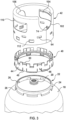
- the gas cylinder 10 includes a gas tank 12 configured to store a suitable pressurized gas, a handle assembly 14 attached to a top of the gas tank 12, and a foot assembly 16 attached to a bottom of the gas tank 12.
- the gas tank 12 may be made of a suitable material, such as metal, and the foot assembly 16 may be made of a suitable material, such as metal or a non-metal material, such as plastic.
- the gas tank 12 includes an upper portion 18 having a valve port 20 and a mounting collar 22 surrounding the valve port 20.
- the mounting collar 22 may be secured to the upper portion 18 in any suitable manner, such as by welding, or may alternatively be integrally formed with the upper portion 18.
- the mounting collar may be made of a suitable material, such as metal, such as a steel of a grade to allow for welding, corrosion resistance, and to absorb tension on the cylinder without significant deformation.
- the mounting collar 22 may be painted and finished with the tank 12 to prevent corrosion, and the paint and weld do not need to be removed during requalification thereby preventing the integrity of the wall of the tank 12 from being compromised.
- the mounting collar 22 has a base 24 attached to the upper portion 18, a flange 26 extending radially inwardly from the base 24, and a plurality of circumferentially spaced openings 28 in the base 24.
- the handle assembly 14 includes a shroud 40 that attaches to the mounting collar 22 and a handle 42 that attaches to the shroud 40.
- the handle assembly has the rigidity to maintain ergonomic integrity while having the flexibility to absorb energy.
- the shroud 40 is substantially cylindrical, with an opening 38 or through passage extending therethrough to surround and abut the mounting collar 22 and to surround the valve port 20.
- the shroud 40 may be made of a suitable material, such as a polymeric material that is compressible to absorb shocks during drops or impacts.
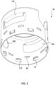
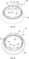
- the shroud includes a plurality of body portions 44 and a plurality of connection portions 46.
- Each connecting portion 46 includes a first plurality of circumferentially spaced fingers 48 extending downward in a first direction towards the tank 12, and a second plurality of circumferentially spaced fingers 50 extending upward in a second direction opposite the first direction away from the tank 12. As shown, each of the first plurality of circumferentially spaced fingers 48 is vertically aligned with one of the second plurality of circumferentially spaced fingers 50, and each connection portion 46 with one of the first and second plurality of circumferentially spaced fingers 48 and 50 is provided between a pair of the body portions 44.
- the body portions 44 and the connection portions 46 with a set of the fingers 48 and 50 alternate with one another in a circumferential direction forming the circular shroud, which as shown is one piece but could be separate pieces coupled together. It will be appreciated, however, that the shroud 40 may be provided with a minimum number of fingers 48 and 50 to engage with the mounting collar 22 and the handle 42 to secure the handle 42 to the tank 12 and prevent rotation of the handle 42 relative to the tank 12.
- Each of the first plurality of fingers 48 is spaced from the respective pair of body portions 44 by slots 52 on opposite sides of the fingers 48, and each of the second plurality of fingers 50 is spaced from the respective pair of body portions 44 by slots 54 on opposite sides of the fingers 50.
- the first and second plurality of circumferentially spaced fingers 48 and 50 are deflectable relative to the body portions 44 for engaging the mounting collar 22 and the handle 42 respectfully.
- the first plurality of circumferentially spaced fingers 48 are configured to deflect radially outwardly away from the valve port 20 during attachment, and each have a catch 56 extending radially inwardly from the finger 48 that engages a respective surface 58 in the openings 28 as shown in FIG. 11 .
- the second plurality of circumferentially spaced fingers 50 are configured to deflect radially inwardly toward the valve port 20 during attachment of the handle 42, and each have a catch 60 extending radially outwardly from the finger 50 that engages a respective surface 62 in a respective opening 64 in the handle 42 as shown in FIG. 14 .
- the first plurality of circumferentially spaced fingers 48 can be spaced from bottoms of the body portions 44 in the second direction to provide a gap between the upper portion 18 and the fingers 48 to prevent interference during installation.
- Each body portion 44 includes a ledge 70 extending radially outwardly at its bottom to provide a surface for a bottom of the handle 42 to abut to space the handle 42 from the upper surface 18 to prevent corrosion.
- Each body portion 44 also includes a slot 72 at its top configured to be abutted by a tab 74 of the handle 42 as will be described in detail below.
- a portion of each body portion 44 forming a base 76 of each slot 72 is surrounded by a lip 78 that surrounds sides of the tabs 74.
- the body portions 44 are substantially U-shaped with a flat bottom such that tops of the body portion are substantially aligned with tops of the second plurality of circumferentially spaced fingers 50.
- the body portions 44 include lateral portions projecting from either side that are below the slots 54 and above the slots 52 connecting the body portions 44 to the connection portions 46.
- the shroud 40 additionally includes a projection 90 extending radially inwardly from the body portions 44 and the first and second plurality of circumferentially spaced fingers 48 and 50.
- the projection 90 is a circular projection having a horizontal portion 92 and a vertical portion 94 extending downward from the horizontal portion 92.
- An underside of the horizontal portion 92 is configured to abut a top of the flange 26 of the mounting collar 22 and an inner side of the vertical portion 94 is configured to abut an inner edge of the flange 26 as shown in FIG. 11 .
- the handle 42 is substantially cylindrical and may be made of a suitable material, such as a high strength lightweight steel, which may be of a different grade and thickness than the mounting collar 22 and tank 12. In this way, the handle 42 can be deformable during an impact or drop to prevent damage to the tank 12.
- the handle 42 includes a body 100 and an opening 102 or through passage extending therethrough to surround and abut the shroud 40 and to surround the valve port 20.
- the body 100 including a plurality of openings 104 and an opening 106 that reduce weight of the handle 42 and provide areas for hanging/holding the cylinder 10, and a cutout 108 that reduces weight and provides an access area for the valve of the cylinder while protecting the valve.
- the body 100 and openings 104 define grip areas 110 at a top of the handle 42 for a user to grasp the handle 42 to transport the cylinder 10, and the body 100 and openings 106 define an area for receiving a hook or other suitable element for hanging the cylinder 10.
- the handle 42 additionally includes the plurality of circumferentially spaced openings 64 that each are configured to receive one of the catches 60 of the second plurality of circumferentially spaced fingers 50, and a plurality of circumferentially spaced openings 112. Projecting radially inwardly from a top of each of the openings 112 is a respective one of the tabs 74 that engage the respective slot 72 in shroud 40. As illustrated, the openings 64 and 112 alternate around the body 102, and the openings 64 are positioned in a direction above the openings 112.
- the handle may be formed of one piece, which may be shaped and ends held together in a suitable manner, such as by welding.
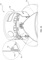
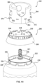
- FIGS. 9-17 show the cylinder 10 with portions cutaway and portions enlarged to illustrate the attachment of the handle assembly 14.
- the handle assembly 14 is removably attached to the collar 22 to allow the shroud 40 and/or handle 42 to be easily replaced, for example if damaged during a drop, without requiring welds to be removed and redone, which could compromise the integrity of the tank 12.
- a user could replace the shroud 40 and/or handle 42, without damaging the weld between the collar 22 and the tank 12.
- the shroud 40 is lowered onto the mounting collar 22 in the first direction.
- the plurality of circumferentially spaced fingers 48 are deflected radially outwardly when they contact the base 24 of the mounting collar 22 as shown in FIG. 10 .
- the plurality of circumferentially spaced fingers 48 remain deflected as they move along the base 24 until they reach a respective one of the plurality of openings 28.
- the plurality of circumferentially spaced fingers 48 move past the respective surfaces 58, the fingers move radially inward to their initial positions and the catches 56 engage the respective surfaces 58 to connect the shroud 40 to the mounting collar 22.
- the horizontal portion 92 of the projection 90 abuts a top of the flange 26 and the vertical portion 94 abuts the inner edge of the flange 26.
- the interaction between the projection 90 and the flange 26 prevents movement of the shroud 40 relative to the mounting collar 22 in the first direction, and the interaction between the catches 56 and the surfaces 58 prevent movement of the shroud 40 relative to the mounting collar 22 in the second direction.
- the interaction between the sides of the catches 56 and the sides of the respective openings 28 prevent rotation of the shroud 40 relative to the mounting collar 22.
- the handle 42 is lowered onto the shroud 40 in the first direction. As the handle 42 is lowered, the bottom of the handle 42 contacts the catches 60 of the plurality of circumferentially spaced tabs 50 as shown in FIG. 12 . As the handle 42 is further lowered, the handle 42 deflects the plurality of circumferentially spaced fingers 50 radially inwardly as shown in FIG. 13 , and the plurality of circumferentially spaced fingers 50 remain deflected as they move along the handle 42 until they reach a respective one of the plurality of openings 64. As the plurality of circumferentially spaced fingers 50 move past the respective surfaces 62, the fingers 50 move radially outwardly to their initial positions and the catches 60 engage the respective surfaces 62 to connect the handle 42 to the shroud 40.
- the plurality of circumferentially spaced tabs 74 of the handle 42 are disposed in the respective slots 72 in the body portions 44 and abut the respective bases 76.
- the interaction between the tabs 74 and the bases 76 and the interaction between the bottom of the handle 42 and the ledge 70 prevents movement of the handle 42 relative to the shroud 40 in the first direction as shown in FIGS. 15 and 16
- the interaction between the catches 60 and the surfaces 62 prevent movement of the handle 42 relative to the shroud 40 in the second direction.
- the interaction between the sides of the catches 60 and the sides of the respective openings 64 prevent rotation of the handle 42 relative to the shroud 40.
- the handle 42 when a force is applied on the handle 42, the force is not resisted by the plurality of circumferentially spaced tabs 50, but instead is resisted by the plurality of tabs 74 compressing against the respective bases 76.
- the metallic handle 42 is spaced from the metallic tank 12 and metallic collar 22 by the ledge 70 of the polymeric shroud 40 as shown in FIGS. 15 and 16 to prevent corrosion between the components.
- the polymeric shroud 40 between the handle 42 and the tank 12 also minimizes deformation of the metal components while providing flexibility to protect the valve.
- the body 100 of the handle 42 is radially outwardly spaced from and abutting or in close proximity to the plurality of circumferentially spaced fingers 48 preventing deflection of the fingers 48 thereby preventing disengage of the shroud 40 from the mounting collar 22.
- a user deflects the plurality of circumferentially spaced tabs 50 radially inwardly disengaging the catches 60 from the surfaces 62 and the handle 42 is moved in the second direction away from the tank 12.
- a user deflects the plurality of circumferentially spaced tabs 48 radially outwardly disengaging the catches 56 from the surfaces 58 and the shroud 40 is moved in the second direction away from the tank 12.
- a replaceable metal handle 42 and replaceable polymer shroud 40 a user can replace the handle 42 without having specialized equipment and without having to damage the welds securing the mounting collar 22 to the tank 12.
- the replaceable metal handle also easily allows for multicolor cylinders, for example for customer or gas identification purposes, for example by providing a tank of a first color and a handle of a second color.
- the gas cylinder 210 is substantially the same as the above-referenced gas cylinder 10, and consequently the same reference numerals but indexed by 200 are used to denote structures corresponding to similar structures in the gas cylinders.
- the foregoing description of the gas cylinder 10 is equally applicable to the gas cylinder 210 except as noted below.
- the gas cylinder 210 includes a gas tank 212 configured to store a suitable pressurized gas, a handle assembly 214 attached to a top of the gas tank 212, and a foot assembly 216 attached to a bottom of the gas tank 212.
- the gas tank 212 includes an upper portion 218 having a valve port 220 for receiving valve 221 and a mounting collar 222 surrounding the valve port 20.
- the mounting collar 222 has a base 224 attached to the upper portion 218, a flange 226 extending radially inwardly from the base 224, and a plurality of circumferentially spaced openings 228 in the base 224.
- the handle assembly 214 includes a shroud 240 that attaches to the mounting collar 222 and a handle 242 that attaches to the shroud 240.
- the handle assembly 214 has the rigidity to maintain ergonomic integrity while having the flexibility to absorb energy.
- the shroud 240 is substantially cylindrical, with an opening 238 or through passage extending therethrough to surround and abut the mounting collar 222 and to surround the valve port 220.
- the shroud 240 may be made of a suitable material, such as a polymeric material that is compressible to absorb shocks during drops or impacts.
- the shroud 240 includes a plurality of body portions 244, a plurality of connection portions 246, and a skirt 266 extending outwardly from the body potions 244.
- Each connecting portion 246 includes a first plurality of circumferentially spaced fingers 248 extending downward in a first direction towards the tank 212, and a second plurality of circumferentially spaced fingers 250 extending upward in a second direction opposite the first direction away from the tank 212.
- each of the first plurality of circumferentially spaced fingers 248 is vertically aligned with one of the second plurality of circumferentially spaced fingers 250, and each connection portion 246 with one of the first and second plurality of circumferentially spaced fingers 248 and 250 is provided between a pair of the body portions 244.
- the body portions 244 and the connection portions 246 with a set of the fingers 248 and 250 alternate with one another in a circumferential direction with the skirt 266 extending outwardly from the body portion 244 forming the circular shroud, which as shown is one piece but could be separate pieces coupled together.
- shroud 240 may be provided with a minimum number of fingers 248 and 250 to engage with the mounting collar 222 and the handle 242 to secure the handle 242 to the tank 212 and prevent rotation of the handle 242 relative to the tank 212.
- Each of the first plurality of fingers 248 is spaced from the respective pair of body portions 244 by slots 252 on opposite sides of the fingers 248, and each of the second plurality of fingers 250 is spaced from the respective pair of body portions 244 by slots 254 on opposite sides of the fingers 250.
- the first and second plurality of circumferentially spaced fingers 248 and 250 are deflectable relative to the body portions 244 for engaging the mounting collar 222 and the handle 242 respectfully.
- the first plurality of circumferentially spaced fingers 248 are configured to deflect radially inwardly toward the valve port 220 during attachment, and each have a catch 256 extending radially outwardly from the finger 248 that engages a respective surface 258 in the openings 228 as shown in FIG. 25 .
- the second plurality of circumferentially spaced fingers 250 are configured to deflect radially outwardly away from the valve port 220 during attachment of the handle 242, and each have a catch 260 extending radially inwardly from the finger 250 that engages a respective surface 262 in a respective opening 264 in the handle 242 as shown in FIG. 25 .
- the first plurality of circumferentially spaced fingers 248 can be spaced from bottoms of the body portions 244 in the second direction to provide a gap between the upper portion 218 and the fingers 248 to prevent interference during installation, for example by ledges 270 that abut the upper surface 218 and that extend radially outwardly from a bottom of each body portion 244.
- Each body portion 244 includes a slot 272 at its top configured to be abutted by a tab 274 of the handle 242 as will be described in detail below.
- a portion of each body portion 244 forming a base 276 of each slot 272 is surrounded by a lip 278 that surrounds sides of the tabs 274.
- the body portions 244 are substantially U-shaped with a flat bottom such that tops of the body portion are substantially aligned with tops of the second plurality of circumferentially spaced fingers 250.
- the body portions 244 include lateral portions projecting from either side that are below the slots 254 and above the slots 252 connecting the body portions 244 to the connection portions 246.
- the handle 242 is substantially cylindrical and may be made of a suitable material, such as a high strength lightweight steel, which may be of a different grade and thickness than the mounting collar 222 and tank 212. In this way, the handle 242 can be deformable during an impact or drop to prevent damage to the tank 212.
- the handle 242 includes a body 300 and an opening 302 or through passage extending therethrough to surround and abut the shroud 240 and to surround the valve port 220.
- the body 300 including a plurality of openings 304 and an opening 306 that reduce weight of the handle 242 and provide areas for hanging/holding the cylinder 210, and a cutout 308 that reduces weight and provides an access area for the valve of the cylinder while protecting the valve.
- the body 300 and openings 304 define grip areas 310 at a top of the handle 242 for a user to grasp the handle 242 to transport the cylinder 210
- the body 300 and openings 306 define an area for receiving a hook or other suitable element for hanging the cylinder 210.
- the handle 242 additionally includes the plurality of circumferentially spaced openings 264 that each are configured to receive one of the catches 260 of the second plurality of circumferentially spaced fingers 250, and a plurality of circumferentially spaced openings 312. Projecting radially outward from a top of each of the openings 312 is a respective one of the tabs 274 that engage the respective slot 272 in shroud 240. As illustrated, the openings 264 and 312 alternate around the body 302, and the openings 264 are positioned in a direction above the openings 312.
- the handle may be formed of one piece, which may be shaped and ends held together in a suitable manner, such as by welding.
- the handle assembly 214 is removably attached to the collar 222 to allow the shroud 240 and/or handle 242 to be easily replaced, for example if damaged during a drop, without requiring welds to be removed and redone, which could compromise the integrity of the tank 212.
- a user could replace the shroud 240 and/or handle 242, without damaging the weld between the collar 222 and the tank 212.
- the shroud 240 is lowered onto the mounting collar 222 in the first direction.
- the plurality of circumferentially spaced fingers 248 are deflected radially inwardly when they contact the base 224 of the mounting collar 222.
- the plurality of circumferentially spaced fingers 248 remain deflected as they move along the base 224 until they reach a respective one of the plurality of openings 228.
- the plurality of circumferentially spaced fingers 248 move past the respective surfaces 258, the fingers move radially outward to their initial positions and the catches 256 engage the respective surfaces 258 to connect the shroud 240 to the mounting collar 222.
- the handle 242 is lowered onto the shroud 240 in the first direction. As the handle 242 is lowered, the bottom of the handle 242 contacts the catches 260 of the plurality of circumferentially spaced tabs 250. As the handle 42 is further lowered within the shroud 240, the handle 242 deflects the plurality of circumferentially spaced fingers 250 radially outwardly, and the plurality of circumferentially spaced fingers 250 remain deflected as they move along the handle 242 until they reach a respective one of the plurality of openings 264. As the plurality of circumferentially spaced fingers 250 move past the respective surfaces 262, the fingers 250 move radially inward to their initial positions and the catches 260 engage the respective surfaces 262 to connect the handle 242 to the shroud 240.
- the plurality of circumferentially spaced tabs 274 of the handle 242 are disposed in the respective slots 272 in the body portions 244 and abut the respective bases 276.
- the interaction between the tabs 274 and the bases 276 prevents movement of the handle 242 relative to the shroud 240 in the first direction
- the interaction between the catches 260 and the surfaces 262 prevent movement of the handle 242 relative to the shroud 240 in the second direction.
- the interaction between the sides of the catches 260 and the sides of the respective openings 264 prevent rotation of the handle 242 relative to the shroud 240.
- the force when a force is applied on the handle 242, the force is not resisted by the plurality of circumferentially spaced tabs 250, but instead is resisted by the plurality of tabs 274 compressing against the respective bases 276, which also space the metallic handle 240 from the metallic tank 212 and metallic collar 222 to prevent corrosion between the components.
- the polymeric shroud 240 between the handle 242 and the tank 212 also minimizes deformation of the metal components while providing flexibility to protect the valve.
- the body 300 of the handle 242 is radially inwardly spaced from and abutting or in close proximity to the plurality of circumferentially spaced fingers 248 preventing deflection of the fingers 248 thereby preventing disengage of the shroud 240 from the mounting collar 222.
- a user deflects the plurality of circumferentially spaced tabs 250 radially outwardly disengaging the catches 260 from the surfaces 262 and the handle 242 is moved in the second direction away from the tank 212.
- a user deflects the plurality of circumferentially spaced tabs 248 radially inwardly disengaging the catches 256 from the surfaces 258 and the shroud 240 is moved in the second direction away from the tank 212.
- the terms “may” and “may be” indicate a possibility of an occurrence within a set of circumstances; a possession of a specified property, characteristic or function; and/or qualify another verb by expressing one or more of an ability, capability, or possibility associated with the qualified verb. Accordingly, usage of “may” and “may be” indicates that a modified term is apparently appropriate, capable, or suitable for an indicated capacity, function, or usage, while taking into account that in some circumstances the modified term may sometimes not be appropriate, capable, or suitable. For example, in some circumstances an event or capacity can be expected, while in other circumstances the event or capacity cannot occur - this distinction is captured by the terms “may” and “may be.”
Landscapes
- Engineering & Computer Science (AREA)
- Mechanical Engineering (AREA)
- General Engineering & Computer Science (AREA)
- Filling Or Discharging Of Gas Storage Vessels (AREA)
Claims (15)
- Transportabler Gaszylinder (10, 210) mit:einem Gastank (12, 212) mit einem oberen Bereich (18, 218) mit einem Ventilanschluss (20, 220); undeiner an dem Gastank (12, 212) angebrachten Griffanordnung (14, 214), wobei die Griffanordnung (14, 214) einen Kragen (40, 240) und einen am Kragen (40, 240) befestigten Griff (42, 424) aufweist,wobei:der Gastank (12, 212) einen Bund (22, 222) aufweist, der den Ventilanschluss (20, 220) umgibt, wobei der Bund eine Mehrzahl von in Umfangsrichtung beabstandeten Öffnungen (28, 228) aufweist;der Kragen (40, 240) der Griffanordnung (14, 214) eine Mehrzahl von in Umfangsrichtung beabstandeten Körperabschnitten (44, 244), eine erste Mehrzahl von in Umfangsrichtung beabstandeten biegbaren Fingern (48, 248), die nach unten in eine erste Richtung verlaufen und die jeweils mit einer jeweiligen der Mehrzahl von in Umfangsrichtung beabstandeten Öffnungen (28, 228) im Bund (22, 222) eingreifen, um den Kragen (40, 240) am Bund (22, 222) zu befestigen, und eine zweite Mehrzahl von in Umfangsrichtung beabstandeten biegbaren Fingern (50, 250) aufweist, die nach oben in eine zweite Richtung verlaufen,der Griff (42, 242) der Griffanordnung (14, 214) ein Körper (100, 300) aufweist, das den Kragen (40, 240) umgibt und daran anliegt, und eine Mehrzahl von in Umfangsrichtung beabstandeten Öffnungen (64, 264) aufweist, die durch der Körper (100, 300) verlaufen;wobei die zweite Mehrzahl von in Umfangsrichtung beabstandeten biegbaren Fingern (50, 250) jeweils in Eingriff mit einer jeweiligen aus der Mehrzahl von in Umfangsrichtung beabstandeten Öffnungen (64, 264) im Griff (42, 242) stehen.
- Transportabler Gaszylinder nach Anspruch 1, wobei die erste Mehrzahl von in Umfangsrichtung beabstandeten biegbaren Fingen (48) während des Zusammenbaus radial nach außen biegbar sind, um jeweils mit einer jeweiligen aus der Mehrzahl von in Umfangsrichtung beabstandeten Öffnungen (28) im Bund (22) in Eingriff zu treten, und die zweite Mehrzahl von in Umfangsrichtung beabstandeten biegbaren Fingern (50) während des Zusammenbaus radial nach innen biegbar sind, um jeweils mit einer jeweiligen aus der Mehrzahl von in Umfangsrichtung beabstandeten Öffnungen (64) im Griff (42) in Eingriff zu treten.
- Transportabler Gaszylinder nach Anspruch 1 oder 2, wobei die erste Mehrzahl von in Umfangsrichtung beabstandeten biegbaren Fingern (48) jeweils einen radial nach innen vorstehenden Haken (56) aufweist, der an einer Oberfläche einer jeweiligen aus der Mehrzahl von in Umfangsrichtung beabstandeten Öffnungen (28) im Bund (22) angreift, und wobei die zweite Mehrzahl von in Umfangsrichtung beabstandeten biegbaren Fingern (50) jeweils einen radial nach außen vorstehenden Haken (60) aufweist, der an einer Oberfläche einer jeweiligen aus der ersten Mehrzahl von in Umfangsrichtung beabstandeten Öffnungen (64) im Griff (42) angreift.
- Transportabler Gaszylinder nach Anspruch 1, wobei die erste Mehrzahl von in Umfangsrichtung beabstandeten biegbaren Fingern (248) während des Zusammenbaus radial nach innen biegbar sind, um in Eingriff mit einer jeweiligen aus der Mehrzahl von in Umfangsrichtung beabstandeten Öffnungen (228) im Bund (222) zu treten, und die zweite Mehrzahl von in Umfangsrichtung beabstandeten biegbaren Fingern (250) während des Zusammenbaus radial nach außen biegbar sind, um mit einer jeweiligen aus der Mehrzahl von in Umfangsrichtung beabstandeten Öffnungen (264) im Griff (242) in Eingriff zu treten.
- Transportabler Gaszylinder nach Anspruch 1 oder 4, wobei die erste Mehrzahl von in Umfangsrichtung beabstandeten biegbaren Fingern (248) jeweils einen radial nach außen vorstehenden Haken (256) aufweisen, der an einer Oberfläche einer jeweiligen aus der Mehrzahl von in Umfangsrichtung beabstandeten Öffnungen (228) im Bund (222) angreift, und wobei die zweite Mehrzahl von in Umfangsrichtung beabstandeten biegbaren Fingern (250) jeweils einen radial nach innen vorstehenden Haken (260) aufweisen, der an einer Oberfläche einer jeweiligen aus der ersten Mehrzahl von in Umfangsrichtung beabstandeten Öffnungen (264) im Griff (242) angreift.
- Transportabler Gaszylinder nach einem der vorhergehenden Ansprüche, wobei jeder aus der ersten Mehrzahl von in Umfangsrichtung beabstandeten Fingern (48, 248) vertikal mit einem aus der zweiten Mehrzahl von in Umfangsrichtung beabstandeten Fingern (50, 250) ausgerichtet ist.
- Transportabler Gaszylinder nach einem der vorhergehenden Ansprüche, wobei eine Oberfläche des Körpers des Griffs (42, 242) in unmittelbarer Nähe zu einer Oberfläche von jedem aus der ersten Mehrzahl von in Umfangsrichtung beabstandeten Fingern (48, 248) liegt, um zu verhindern, dass die erste Mehrzahl von in Umfangsrichtung beabstandeten Fingern (48, 248) gebogen werden.
- Transportabler Gaszylinder nach Anspruch 6 oder 7, wobei einer von jeder aus der ersten und zweiten Mehrzahl von in Umfangsrichtung beabstandeten Fingern (48, 248 und 50, 250) zwischen einem Paar von in Umfangsrichtung beabstandeten Körperabschnitten (44, 244) positioniert ist.
- Transportabler Gaszylinder nach Anspruch 8, wobei die Mehrzahl von in Umfangsrichtung beabstandeten Körperabschnitten (44, 244) und die vertikal ausgerichtete erste Mehrzahl und zweite Mehrzahl von in Umfangsrichtung beabstandeten Fingern (48, 248 und 50, 250) sich in Umfangsrichtung abwechseln.
- Transportabler Gaszylinder nach Anspruch 8 oder 9, wobei jeder Körperabschnitt (44, 244) an seinem Boden einen radial nach außen vorstehenden Vorsprung (70, 270) aufweist, der dazu ausgestaltet ist, mit einem Boden des Griffs (42, 242) in Kontakt zu kommen, um den Boden des Griffs (42, 242) auf Abstand zu dem Tank (12, 212) zu halten.
- Transportabler Gaszylinder nach einem der vorhergehenden Ansprüche, wobei der Griff (42, 242) eine Mehrzahl von in Umfangsrichtung beabstandeten, von dem Körper radial nach innen vorstehenden Rastnasen (74, 274) aufweist, wobei jede Rastnase (74, 274) dazu ausgestaltet ist, in einem jeweiligen Schlitz im Kragen (40, 240) anzuliegen.
- Transportabler Gaszylinder nach Anspruch 11, wobei die Griffanordnung eine zweite Mehrzahl von in Umfangsrichtung beabstandeten Öffnungen (112, 312) aufweist, und wobei eine aus der Mehrzahl von in Umfangsrichtung beabstandeten Rastnasen (74, 274) von einer Oberseite von jeder aus der zweiten Mehrzahl von in Umfangsrichtung beabstandeten Öffnungen (112, 312) verläuft.
- Tragbarer Gaszylinder nach einem der vorhergehenden Ansprüche, wobei der Kragen (40) weiterhin einen kreisförmigen Vorsprung (90) aufweist, der von einer inneren Oberfläche des Kragens radial nach innen vorsteht und der dazu ausgestaltet ist, um an dem Bund (22) anzuliegen.
- Transportabler Gaszylinder nach einem der vorhergehenden Ansprüche, wobei der Kragen (40, 240) aus einem Polymer hergestellt ist und der Griff (22, 242) aus Metall hergestellt ist.
- Verfahren zum Zusammenbau des transportablen Gaszylinders (10, 210) nach einem der Ansprüche 1-14, wobei bei dem Verfahren:der Kragen (40, 240) der Griffanordnung (14, 214) auf den Montagebund abgesenkt wird, um zu bewirken, dass die erste Mehrzahl von in Umfangsrichtung beabstandeten Fingern (48, 248) des Kragens (40, 240) durch den Montagebund (22, 222) radial nach außen oder innen gebogen werden, bis die Haken (56, 256) der ersten Mehrzahl von in Umfangsrichtung beabstandeten Fingern (48, 248) in einer jeweiligen aus der Mehrzahl von in Umfangsrichtung beabstandeten Öffnungen (28, 228) im Montagebund (22, 222) eingreifen; undder Griff (42, 242) der Griffanordnung (14, 214) auf den Kragen (40, 240) abgesenkt wird, um zu bewirken, dass die zweite Mehrzahl von in Umfangsrichtung beabstandeten Fingern (50, 250) des Kragens (40, 240) von dem Griff (42, 242) radial nach innen oder außen gebogen werden, bis die Haken (60, 260) der zweiten Mehrzahl von in Umfangsrichtung beabstandeten Fingern (50, 250) in einer jeweiligen aus der Mehrzahl von in Umfangsrichtung beabstandeten Öffnungen (64, 264) im Griff eingreifen.
Applications Claiming Priority (2)
| Application Number | Priority Date | Filing Date | Title |
|---|---|---|---|
| US16/559,037 US10982814B2 (en) | 2019-09-03 | 2019-09-03 | Handle assembly for a portable pressurized gas cylinder |
| PCT/US2020/032865 WO2021045807A1 (en) | 2019-09-03 | 2020-05-14 | Handle assembly for a portable pressurized gas cylinder |
Publications (2)
| Publication Number | Publication Date |
|---|---|
| EP4025825A1 EP4025825A1 (de) | 2022-07-13 |
| EP4025825B1 true EP4025825B1 (de) | 2024-09-04 |
Family
ID=70978572
Family Applications (1)
| Application Number | Title | Priority Date | Filing Date |
|---|---|---|---|
| EP20730805.7A Active EP4025825B1 (de) | 2019-09-03 | 2020-05-14 | Griffanordnung für einen tragbaren druckgaszylinder |
Country Status (5)
| Country | Link |
|---|---|
| US (1) | US10982814B2 (de) |
| EP (1) | EP4025825B1 (de) |
| PL (1) | PL4025825T3 (de) |
| PT (1) | PT4025825T (de) |
| WO (1) | WO2021045807A1 (de) |
Families Citing this family (3)
| Publication number | Priority date | Publication date | Assignee | Title |
|---|---|---|---|---|
| US11988335B2 (en) * | 2020-10-02 | 2024-05-21 | Ditech Manufacturing Ltd. | Foot ring and collar for pressurized tank |
| US12129970B2 (en) * | 2023-02-17 | 2024-10-29 | Amtrol Licensing Inc. | Handle for a portable cylinder |
| USD1124227S1 (en) * | 2023-02-17 | 2026-04-28 | Amtrol Licensing Inc. | Handle |
Family Cites Families (14)
| Publication number | Priority date | Publication date | Assignee | Title |
|---|---|---|---|---|
| FR1564018A (de) * | 1968-03-04 | 1969-04-18 | ||
| US6854919B2 (en) * | 2002-06-20 | 2005-02-15 | S.C. Johnson & Son, Inc. | Push-lock handle assembly |
| FR2880404B1 (fr) * | 2005-01-05 | 2007-07-20 | Air Liquide | Ensemble de stockage de gaz sous pression |
| TR200502731A2 (tr) * | 2005-07-13 | 2007-02-21 | Aygaz Anoni̇m Şi̇rketi̇ | Bir tüp. |
| DE102008057632B4 (de) * | 2008-11-10 | 2015-01-22 | Huber Packaging Group Gmbh | Tragevorrichtung |
| US8215517B2 (en) * | 2008-12-17 | 2012-07-10 | Amtrol Licensing, Inc. | Compressed gas cylinder having conductive polymeric foot ring |
| US20130277376A1 (en) * | 2010-09-20 | 2013-10-24 | Adrienne Liebenberg | Pressure vessel |
| US8944278B2 (en) | 2011-03-31 | 2015-02-03 | Amtrol Licensing Inc. | Clip-on handle grips |
| BRPI1102874B1 (pt) * | 2011-06-22 | 2021-12-07 | Somma Technology Engenharia Ltda | Conjunto de anéis de alça e de base substituíveis para um reservatório pressurizado e reservatório pressurizado |
| US9932148B2 (en) * | 2015-01-23 | 2018-04-03 | Amtrol Licensing Inc. | Handle assembly for a portable pressurized gas cylinder |
| US10688648B2 (en) * | 2015-12-07 | 2020-06-23 | Monahan Partners, Inc. | Multi-component quick assembly handle |
| EP3193072B1 (de) | 2016-01-12 | 2017-12-13 | Rovip | Universalschutzvorrichtung für gasflasche |
| DE102017007162A1 (de) | 2017-07-27 | 2019-01-31 | Messer Gaspack Gmbh | Ventilschutzeinrichtung für Druckgasbehälter |
| MA43446B1 (fr) * | 2018-10-01 | 2020-07-29 | Imaplast | Collet protecteur de valve pour bouteilles gpl |
-
2019
- 2019-09-03 US US16/559,037 patent/US10982814B2/en active Active
-
2020
- 2020-05-14 PT PT207308057T patent/PT4025825T/pt unknown
- 2020-05-14 EP EP20730805.7A patent/EP4025825B1/de active Active
- 2020-05-14 PL PL20730805.7T patent/PL4025825T3/pl unknown
- 2020-05-14 WO PCT/US2020/032865 patent/WO2021045807A1/en not_active Ceased
Also Published As
| Publication number | Publication date |
|---|---|
| WO2021045807A1 (en) | 2021-03-11 |
| PL4025825T3 (pl) | 2025-02-24 |
| PT4025825T (pt) | 2024-11-28 |
| EP4025825A1 (de) | 2022-07-13 |
| US20210062975A1 (en) | 2021-03-04 |
| US10982814B2 (en) | 2021-04-20 |
Similar Documents
| Publication | Publication Date | Title |
|---|---|---|
| US12181104B2 (en) | Handle for a portable cylinder | |
| US10982814B2 (en) | Handle assembly for a portable pressurized gas cylinder | |
| EP3794271B1 (de) | Griffanordnung für einen tragbaren druckgaszylinder | |
| EP2724074B1 (de) | Austauschbare griff- und stütz-/basisringelemente für einen druckbehälter und druckbehälter | |
| US5752608A (en) | Spacer rack for stacking wheel rims | |
| US12129970B2 (en) | Handle for a portable cylinder | |
| JP3588142B2 (ja) | 圧力容器の安全装置 | |
| KR20070122351A (ko) | 팔레트 컨테이너 용 식별 플레이트 | |
| CA1213533A (en) | Removable protective skirt for a tank | |
| US20090152270A1 (en) | Orientation system for a closure | |
| US12631297B2 (en) | Handle for a portable cylinder | |
| CN213677688U (zh) | 一种双层托盘 | |
| CN112208895A (zh) | 一种双层托盘 | |
| WO2012107212A1 (en) | A paint container with a releasably secured liner | |
| JP2010052842A (ja) | 自動倉庫のラック | |
| CN213677702U (zh) | 一种托盘护板 | |
| CN210339069U (zh) | 罐式集装箱及其保护盒 | |
| CN213677686U (zh) | 一种托盘双层支腿 | |
| EP4465461A1 (de) | Hebe- und handhabungszubehör, schrank für eine elektrische schalttafel mit diesem zubehör und hebe- und handhabungssatz | |
| EP3817867B1 (de) | Trommelrahmen schutzabdeckung | |
| TR2022011669T2 (tr) | Handle for a portable cylinder | |
| US10107440B2 (en) | Devices and assembly for protecting a flange | |
| US668521A (en) | Metallic receptacle. | |
| WO2019243881A1 (en) | An outer cage for a pallet container enabled by a half through riveting method |
Legal Events
| Date | Code | Title | Description |
|---|---|---|---|
| STAA | Information on the status of an ep patent application or granted ep patent |
Free format text: STATUS: UNKNOWN |
|
| STAA | Information on the status of an ep patent application or granted ep patent |
Free format text: STATUS: THE INTERNATIONAL PUBLICATION HAS BEEN MADE |
|
| PUAI | Public reference made under article 153(3) epc to a published international application that has entered the european phase |
Free format text: ORIGINAL CODE: 0009012 |
|
| STAA | Information on the status of an ep patent application or granted ep patent |
Free format text: STATUS: REQUEST FOR EXAMINATION WAS MADE |
|
| 17P | Request for examination filed |
Effective date: 20220331 |
|
| AK | Designated contracting states |
Kind code of ref document: A1 Designated state(s): AL AT BE BG CH CY CZ DE DK EE ES FI FR GB GR HR HU IE IS IT LI LT LU LV MC MK MT NL NO PL PT RO RS SE SI SK SM TR |
|
| DAV | Request for validation of the european patent (deleted) | ||
| DAX | Request for extension of the european patent (deleted) | ||
| GRAP | Despatch of communication of intention to grant a patent |
Free format text: ORIGINAL CODE: EPIDOSNIGR1 |
|
| STAA | Information on the status of an ep patent application or granted ep patent |
Free format text: STATUS: GRANT OF PATENT IS INTENDED |
|
| INTG | Intention to grant announced |
Effective date: 20240430 |
|
| GRAS | Grant fee paid |
Free format text: ORIGINAL CODE: EPIDOSNIGR3 |
|
| GRAA | (expected) grant |
Free format text: ORIGINAL CODE: 0009210 |
|
| STAA | Information on the status of an ep patent application or granted ep patent |
Free format text: STATUS: THE PATENT HAS BEEN GRANTED |
|
| AK | Designated contracting states |
Kind code of ref document: B1 Designated state(s): AL AT BE BG CH CY CZ DE DK EE ES FI FR GB GR HR HU IE IS IT LI LT LU LV MC MK MT NL NO PL PT RO RS SE SI SK SM TR |
|
| REG | Reference to a national code |
Ref country code: GB Ref legal event code: FG4D |
|
| REG | Reference to a national code |
Ref country code: CH Ref legal event code: EP |
|
| REG | Reference to a national code |
Ref country code: IE Ref legal event code: FG4D |
|
| REG | Reference to a national code |
Ref country code: DE Ref legal event code: R096 Ref document number: 602020037062 Country of ref document: DE |
|
| P01 | Opt-out of the competence of the unified patent court (upc) registered |
Free format text: CASE NUMBER: APP_50175/2024 Effective date: 20240904 |
|
| REG | Reference to a national code |
Ref country code: PT Ref legal event code: SC4A Ref document number: 4025825 Country of ref document: PT Date of ref document: 20241128 Kind code of ref document: T Free format text: AVAILABILITY OF NATIONAL TRANSLATION Effective date: 20241121 |
|
| REG | Reference to a national code |
Ref country code: LT Ref legal event code: MG9D |
|
| REG | Reference to a national code |
Ref country code: NL Ref legal event code: MP Effective date: 20240904 |
|
| PG25 | Lapsed in a contracting state [announced via postgrant information from national office to epo] |
Ref country code: NO Free format text: LAPSE BECAUSE OF FAILURE TO SUBMIT A TRANSLATION OF THE DESCRIPTION OR TO PAY THE FEE WITHIN THE PRESCRIBED TIME-LIMIT Effective date: 20241204 |
|
| PG25 | Lapsed in a contracting state [announced via postgrant information from national office to epo] |
Ref country code: GR Free format text: LAPSE BECAUSE OF FAILURE TO SUBMIT A TRANSLATION OF THE DESCRIPTION OR TO PAY THE FEE WITHIN THE PRESCRIBED TIME-LIMIT Effective date: 20241205 Ref country code: FI Free format text: LAPSE BECAUSE OF FAILURE TO SUBMIT A TRANSLATION OF THE DESCRIPTION OR TO PAY THE FEE WITHIN THE PRESCRIBED TIME-LIMIT Effective date: 20240904 |
|
| PG25 | Lapsed in a contracting state [announced via postgrant information from national office to epo] |
Ref country code: BG Free format text: LAPSE BECAUSE OF FAILURE TO SUBMIT A TRANSLATION OF THE DESCRIPTION OR TO PAY THE FEE WITHIN THE PRESCRIBED TIME-LIMIT Effective date: 20240904 |
|
| PG25 | Lapsed in a contracting state [announced via postgrant information from national office to epo] |
Ref country code: LV Free format text: LAPSE BECAUSE OF FAILURE TO SUBMIT A TRANSLATION OF THE DESCRIPTION OR TO PAY THE FEE WITHIN THE PRESCRIBED TIME-LIMIT Effective date: 20240904 |
|
| PG25 | Lapsed in a contracting state [announced via postgrant information from national office to epo] |
Ref country code: HR Free format text: LAPSE BECAUSE OF FAILURE TO SUBMIT A TRANSLATION OF THE DESCRIPTION OR TO PAY THE FEE WITHIN THE PRESCRIBED TIME-LIMIT Effective date: 20240904 |
|
| PG25 | Lapsed in a contracting state [announced via postgrant information from national office to epo] |
Ref country code: ES Free format text: LAPSE BECAUSE OF FAILURE TO SUBMIT A TRANSLATION OF THE DESCRIPTION OR TO PAY THE FEE WITHIN THE PRESCRIBED TIME-LIMIT Effective date: 20240904 Ref country code: RS Free format text: LAPSE BECAUSE OF FAILURE TO SUBMIT A TRANSLATION OF THE DESCRIPTION OR TO PAY THE FEE WITHIN THE PRESCRIBED TIME-LIMIT Effective date: 20241204 |
|
| PG25 | Lapsed in a contracting state [announced via postgrant information from national office to epo] |
Ref country code: RS Free format text: LAPSE BECAUSE OF FAILURE TO SUBMIT A TRANSLATION OF THE DESCRIPTION OR TO PAY THE FEE WITHIN THE PRESCRIBED TIME-LIMIT Effective date: 20241204 Ref country code: NO Free format text: LAPSE BECAUSE OF FAILURE TO SUBMIT A TRANSLATION OF THE DESCRIPTION OR TO PAY THE FEE WITHIN THE PRESCRIBED TIME-LIMIT Effective date: 20241204 Ref country code: LV Free format text: LAPSE BECAUSE OF FAILURE TO SUBMIT A TRANSLATION OF THE DESCRIPTION OR TO PAY THE FEE WITHIN THE PRESCRIBED TIME-LIMIT Effective date: 20240904 Ref country code: HR Free format text: LAPSE BECAUSE OF FAILURE TO SUBMIT A TRANSLATION OF THE DESCRIPTION OR TO PAY THE FEE WITHIN THE PRESCRIBED TIME-LIMIT Effective date: 20240904 Ref country code: GR Free format text: LAPSE BECAUSE OF FAILURE TO SUBMIT A TRANSLATION OF THE DESCRIPTION OR TO PAY THE FEE WITHIN THE PRESCRIBED TIME-LIMIT Effective date: 20241205 Ref country code: FI Free format text: LAPSE BECAUSE OF FAILURE TO SUBMIT A TRANSLATION OF THE DESCRIPTION OR TO PAY THE FEE WITHIN THE PRESCRIBED TIME-LIMIT Effective date: 20240904 Ref country code: ES Free format text: LAPSE BECAUSE OF FAILURE TO SUBMIT A TRANSLATION OF THE DESCRIPTION OR TO PAY THE FEE WITHIN THE PRESCRIBED TIME-LIMIT Effective date: 20240904 Ref country code: BG Free format text: LAPSE BECAUSE OF FAILURE TO SUBMIT A TRANSLATION OF THE DESCRIPTION OR TO PAY THE FEE WITHIN THE PRESCRIBED TIME-LIMIT Effective date: 20240904 |
|
| REG | Reference to a national code |
Ref country code: AT Ref legal event code: MK05 Ref document number: 1720731 Country of ref document: AT Kind code of ref document: T Effective date: 20240904 |
|
| PG25 | Lapsed in a contracting state [announced via postgrant information from national office to epo] |
Ref country code: NL Free format text: LAPSE BECAUSE OF FAILURE TO SUBMIT A TRANSLATION OF THE DESCRIPTION OR TO PAY THE FEE WITHIN THE PRESCRIBED TIME-LIMIT Effective date: 20240904 |
|
| PG25 | Lapsed in a contracting state [announced via postgrant information from national office to epo] |
Ref country code: IS Free format text: LAPSE BECAUSE OF FAILURE TO SUBMIT A TRANSLATION OF THE DESCRIPTION OR TO PAY THE FEE WITHIN THE PRESCRIBED TIME-LIMIT Effective date: 20250104 |
|
| PG25 | Lapsed in a contracting state [announced via postgrant information from national office to epo] |
Ref country code: SM Free format text: LAPSE BECAUSE OF FAILURE TO SUBMIT A TRANSLATION OF THE DESCRIPTION OR TO PAY THE FEE WITHIN THE PRESCRIBED TIME-LIMIT Effective date: 20240904 Ref country code: RO Free format text: LAPSE BECAUSE OF FAILURE TO SUBMIT A TRANSLATION OF THE DESCRIPTION OR TO PAY THE FEE WITHIN THE PRESCRIBED TIME-LIMIT Effective date: 20240904 |
|
| PG25 | Lapsed in a contracting state [announced via postgrant information from national office to epo] |
Ref country code: AT Free format text: LAPSE BECAUSE OF FAILURE TO SUBMIT A TRANSLATION OF THE DESCRIPTION OR TO PAY THE FEE WITHIN THE PRESCRIBED TIME-LIMIT Effective date: 20240904 Ref country code: EE Free format text: LAPSE BECAUSE OF FAILURE TO SUBMIT A TRANSLATION OF THE DESCRIPTION OR TO PAY THE FEE WITHIN THE PRESCRIBED TIME-LIMIT Effective date: 20240904 |
|
| PG25 | Lapsed in a contracting state [announced via postgrant information from national office to epo] |
Ref country code: CZ Free format text: LAPSE BECAUSE OF FAILURE TO SUBMIT A TRANSLATION OF THE DESCRIPTION OR TO PAY THE FEE WITHIN THE PRESCRIBED TIME-LIMIT Effective date: 20240904 |
|
| PG25 | Lapsed in a contracting state [announced via postgrant information from national office to epo] |
Ref country code: IT Free format text: LAPSE BECAUSE OF FAILURE TO SUBMIT A TRANSLATION OF THE DESCRIPTION OR TO PAY THE FEE WITHIN THE PRESCRIBED TIME-LIMIT Effective date: 20240904 Ref country code: SK Free format text: LAPSE BECAUSE OF FAILURE TO SUBMIT A TRANSLATION OF THE DESCRIPTION OR TO PAY THE FEE WITHIN THE PRESCRIBED TIME-LIMIT Effective date: 20240904 |
|
| REG | Reference to a national code |
Ref country code: DE Ref legal event code: R097 Ref document number: 602020037062 Country of ref document: DE |
|
| PG25 | Lapsed in a contracting state [announced via postgrant information from national office to epo] |
Ref country code: DK Free format text: LAPSE BECAUSE OF FAILURE TO SUBMIT A TRANSLATION OF THE DESCRIPTION OR TO PAY THE FEE WITHIN THE PRESCRIBED TIME-LIMIT Effective date: 20240904 |
|
| PLBE | No opposition filed within time limit |
Free format text: ORIGINAL CODE: 0009261 |
|
| STAA | Information on the status of an ep patent application or granted ep patent |
Free format text: STATUS: NO OPPOSITION FILED WITHIN TIME LIMIT |
|
| 26N | No opposition filed |
Effective date: 20250605 |
|
| PG25 | Lapsed in a contracting state [announced via postgrant information from national office to epo] |
Ref country code: SE Free format text: LAPSE BECAUSE OF FAILURE TO SUBMIT A TRANSLATION OF THE DESCRIPTION OR TO PAY THE FEE WITHIN THE PRESCRIBED TIME-LIMIT Effective date: 20240904 |
|
| REG | Reference to a national code |
Ref country code: DE Ref legal event code: R119 Ref document number: 602020037062 Country of ref document: DE |
|
| REG | Reference to a national code |
Ref country code: CH Ref legal event code: H13 Free format text: ST27 STATUS EVENT CODE: U-0-0-H10-H13 (AS PROVIDED BY THE NATIONAL OFFICE) Effective date: 20251223 |
|
| PG25 | Lapsed in a contracting state [announced via postgrant information from national office to epo] |
Ref country code: LU Free format text: LAPSE BECAUSE OF NON-PAYMENT OF DUE FEES Effective date: 20250514 |
|
| PG25 | Lapsed in a contracting state [announced via postgrant information from national office to epo] |
Ref country code: CH Free format text: LAPSE BECAUSE OF NON-PAYMENT OF DUE FEES Effective date: 20250531 |
|
| GBPC | Gb: european patent ceased through non-payment of renewal fee |
Effective date: 20250514 |
|
| REG | Reference to a national code |
Ref country code: BE Ref legal event code: MM Effective date: 20250531 |
|
| PG25 | Lapsed in a contracting state [announced via postgrant information from national office to epo] |
Ref country code: MC Free format text: LAPSE BECAUSE OF FAILURE TO SUBMIT A TRANSLATION OF THE DESCRIPTION OR TO PAY THE FEE WITHIN THE PRESCRIBED TIME-LIMIT Effective date: 20240904 |
|
| PG25 | Lapsed in a contracting state [announced via postgrant information from national office to epo] |
Ref country code: GB Free format text: LAPSE BECAUSE OF NON-PAYMENT OF DUE FEES Effective date: 20250514 |
|
| PG25 | Lapsed in a contracting state [announced via postgrant information from national office to epo] |
Ref country code: DE Free format text: LAPSE BECAUSE OF NON-PAYMENT OF DUE FEES Effective date: 20251202 Ref country code: IE Free format text: LAPSE BECAUSE OF NON-PAYMENT OF DUE FEES Effective date: 20250514 |
|
| PG25 | Lapsed in a contracting state [announced via postgrant information from national office to epo] |
Ref country code: BE Free format text: LAPSE BECAUSE OF NON-PAYMENT OF DUE FEES Effective date: 20250531 |
|
| PG25 | Lapsed in a contracting state [announced via postgrant information from national office to epo] |
Ref country code: FR Free format text: LAPSE BECAUSE OF NON-PAYMENT OF DUE FEES Effective date: 20250531 |
|
| PG25 | Lapsed in a contracting state [announced via postgrant information from national office to epo] |
Ref country code: PT Free format text: LAPSE BECAUSE OF NON-PAYMENT OF DUE FEES Effective date: 20260216 |