EP4025841B1 - Dispositif de retenue destiné à retenir un capteur de mesure et à transmettre un signal de mesure électrique - Google Patents
Dispositif de retenue destiné à retenir un capteur de mesure et à transmettre un signal de mesure électrique Download PDFInfo
- Publication number
- EP4025841B1 EP4025841B1 EP20768320.2A EP20768320A EP4025841B1 EP 4025841 B1 EP4025841 B1 EP 4025841B1 EP 20768320 A EP20768320 A EP 20768320A EP 4025841 B1 EP4025841 B1 EP 4025841B1
- Authority
- EP
- European Patent Office
- Prior art keywords
- hold
- fluid carrying
- measuring sensor
- connection
- component
- Prior art date
- Legal status (The legal status is an assumption and is not a legal conclusion. Google has not performed a legal analysis and makes no representation as to the accuracy of the status listed.)
- Active
Links
Images



Classifications
-
- G—PHYSICS
- G01—MEASURING; TESTING
- G01R—MEASURING ELECTRIC VARIABLES; MEASURING MAGNETIC VARIABLES
- G01R27/00—Arrangements for measuring resistance, reactance, impedance, or electric characteristics derived therefrom
- G01R27/02—Measuring real or complex resistance, reactance, impedance, or other two-pole characteristics derived therefrom, e.g. time constant
- G01R27/22—Measuring resistance of fluids
-
- F—MECHANICAL ENGINEERING; LIGHTING; HEATING; WEAPONS; BLASTING
- F24—HEATING; RANGES; VENTILATING
- F24H—FLUID HEATERS, e.g. WATER OR AIR HEATERS, HAVING HEAT-GENERATING MEANS, e.g. HEAT PUMPS, IN GENERAL
- F24H1/00—Water heaters, e.g. boilers, continuous-flow heaters or water-storage heaters
- F24H1/10—Continuous-flow heaters, i.e. heaters in which heat is generated only while the water is flowing, e.g. with direct contact of the water with the heating medium
- F24H1/101—Continuous-flow heaters, i.e. heaters in which heat is generated only while the water is flowing, e.g. with direct contact of the water with the heating medium using electric energy supply
-
- F—MECHANICAL ENGINEERING; LIGHTING; HEATING; WEAPONS; BLASTING
- F24—HEATING; RANGES; VENTILATING
- F24H—FLUID HEATERS, e.g. WATER OR AIR HEATERS, HAVING HEAT-GENERATING MEANS, e.g. HEAT PUMPS, IN GENERAL
- F24H15/00—Control of fluid heaters
- F24H15/20—Control of fluid heaters characterised by control inputs
-
- F—MECHANICAL ENGINEERING; LIGHTING; HEATING; WEAPONS; BLASTING
- F24—HEATING; RANGES; VENTILATING
- F24H—FLUID HEATERS, e.g. WATER OR AIR HEATERS, HAVING HEAT-GENERATING MEANS, e.g. HEAT PUMPS, IN GENERAL
- F24H15/00—Control of fluid heaters
- F24H15/30—Control of fluid heaters characterised by control outputs; characterised by the components to be controlled
- F24H15/305—Control of valves
- F24H15/31—Control of valves of valves having only one inlet port and one outlet port, e.g. flow rate regulating valves
-
- F—MECHANICAL ENGINEERING; LIGHTING; HEATING; WEAPONS; BLASTING
- F24—HEATING; RANGES; VENTILATING
- F24H—FLUID HEATERS, e.g. WATER OR AIR HEATERS, HAVING HEAT-GENERATING MEANS, e.g. HEAT PUMPS, IN GENERAL
- F24H15/00—Control of fluid heaters
- F24H15/30—Control of fluid heaters characterised by control outputs; characterised by the components to be controlled
- F24H15/355—Control of heat-generating means in heaters
- F24H15/37—Control of heat-generating means in heaters of electric heaters
-
- F—MECHANICAL ENGINEERING; LIGHTING; HEATING; WEAPONS; BLASTING
- F24—HEATING; RANGES; VENTILATING
- F24H—FLUID HEATERS, e.g. WATER OR AIR HEATERS, HAVING HEAT-GENERATING MEANS, e.g. HEAT PUMPS, IN GENERAL
- F24H9/00—Details
- F24H9/20—Arrangement or mounting of control or safety devices
- F24H9/2007—Arrangement or mounting of control or safety devices for water heaters
- F24H9/2014—Arrangement or mounting of control or safety devices for water heaters using electrical energy supply
- F24H9/2028—Continuous-flow heaters
-
- G—PHYSICS
- G01—MEASURING; TESTING
- G01N—INVESTIGATING OR ANALYSING MATERIALS BY DETERMINING THEIR CHEMICAL OR PHYSICAL PROPERTIES
- G01N27/00—Investigating or analysing materials by the use of electric, electrochemical, or magnetic means
- G01N27/02—Investigating or analysing materials by the use of electric, electrochemical, or magnetic means by investigating impedance
- G01N27/04—Investigating or analysing materials by the use of electric, electrochemical, or magnetic means by investigating impedance by investigating resistance
- G01N27/06—Investigating or analysing materials by the use of electric, electrochemical, or magnetic means by investigating impedance by investigating resistance of a liquid
- G01N27/07—Construction of measuring vessels; Electrodes therefor
-
- G—PHYSICS
- G01—MEASURING; TESTING
- G01N—INVESTIGATING OR ANALYSING MATERIALS BY DETERMINING THEIR CHEMICAL OR PHYSICAL PROPERTIES
- G01N27/00—Investigating or analysing materials by the use of electric, electrochemical, or magnetic means
- G01N27/02—Investigating or analysing materials by the use of electric, electrochemical, or magnetic means by investigating impedance
- G01N27/04—Investigating or analysing materials by the use of electric, electrochemical, or magnetic means by investigating impedance by investigating resistance
- G01N27/06—Investigating or analysing materials by the use of electric, electrochemical, or magnetic means by investigating impedance by investigating resistance of a liquid
- G01N27/08—Investigating or analysing materials by the use of electric, electrochemical, or magnetic means by investigating impedance by investigating resistance of a liquid which is flowing continuously
-
- G—PHYSICS
- G01—MEASURING; TESTING
- G01R—MEASURING ELECTRIC VARIABLES; MEASURING MAGNETIC VARIABLES
- G01R1/00—Details of instruments or arrangements of the types included in groups G01R5/00 - G01R13/00 and G01R31/00
- G01R1/02—General constructional details
- G01R1/04—Housings; Supporting members; Arrangements of terminals
- G01R1/0408—Test fixtures or contact fields; Connectors or connecting adaptors; Test clips; Test sockets
-
- H—ELECTRICITY
- H02—GENERATION; CONVERSION OR DISTRIBUTION OF ELECTRIC POWER
- H02H—EMERGENCY PROTECTIVE CIRCUIT ARRANGEMENTS
- H02H1/00—Details of emergency protective circuit arrangements
- H02H1/0007—Details of emergency protective circuit arrangements concerning the detecting means
-
- F—MECHANICAL ENGINEERING; LIGHTING; HEATING; WEAPONS; BLASTING
- F24—HEATING; RANGES; VENTILATING
- F24D—DOMESTIC- OR SPACE-HEATING SYSTEMS, e.g. CENTRAL HEATING SYSTEMS; DOMESTIC HOT-WATER SUPPLY SYSTEMS; ELEMENTS OR COMPONENTS THEREFOR
- F24D2220/00—Components of central heating installations excluding heat sources
- F24D2220/04—Sensors
-
- F—MECHANICAL ENGINEERING; LIGHTING; HEATING; WEAPONS; BLASTING
- F24—HEATING; RANGES; VENTILATING
- F24H—FLUID HEATERS, e.g. WATER OR AIR HEATERS, HAVING HEAT-GENERATING MEANS, e.g. HEAT PUMPS, IN GENERAL
- F24H15/00—Control of fluid heaters
- F24H15/20—Control of fluid heaters characterised by control inputs
- F24H15/212—Temperature of the water
- F24H15/215—Temperature of the water before heating
-
- F—MECHANICAL ENGINEERING; LIGHTING; HEATING; WEAPONS; BLASTING
- F24—HEATING; RANGES; VENTILATING
- F24H—FLUID HEATERS, e.g. WATER OR AIR HEATERS, HAVING HEAT-GENERATING MEANS, e.g. HEAT PUMPS, IN GENERAL
- F24H15/00—Control of fluid heaters
- F24H15/20—Control of fluid heaters characterised by control inputs
- F24H15/212—Temperature of the water
- F24H15/219—Temperature of the water after heating
-
- F—MECHANICAL ENGINEERING; LIGHTING; HEATING; WEAPONS; BLASTING
- F24—HEATING; RANGES; VENTILATING
- F24H—FLUID HEATERS, e.g. WATER OR AIR HEATERS, HAVING HEAT-GENERATING MEANS, e.g. HEAT PUMPS, IN GENERAL
- F24H15/00—Control of fluid heaters
- F24H15/20—Control of fluid heaters characterised by control inputs
- F24H15/238—Flow rate
Definitions
- the invention relates to a fluid-conducting assembly for a domestic appliance, in particular a continuous flow heater, with a fluid-conducting component with a fluid-conducting component line section extending through the component, which has a connection on opposite sides for connection to a fluid-conducting line; and a measuring sensor that at least partially projects into the component line section.
- Fluid-carrying domestic appliances are, for example, instantaneous water heaters, which are used to generate hot water using electrical energy in particular.
- Such an instantaneous water heater comprises one or more electrical heating elements, with the aid of which a fluid, typically water, guided through channels in the instantaneous water heater can be heated to a desired, preset temperature depending on the electrical power supplied to the heating elements.
- Instantaneous water heaters supply hot water without standby losses because they only heat water when hot water is needed.
- Modern instantaneous water heaters are equipped with either a bare wire heating element or a metal-coated heating element.
- the potential difference between the bare wire and the water inlet channel or the water outlet channel that are electrically connected to the earth potential leads to corresponding leakage currents during operation of the heating device. Accordingly, leakage paths are provided so that excessive electrical leakage currents are prevented in particular at the water inlet and water outlet connections that are connected to the earth potential.
- the size of these leakage currents depends, among other things, on the conductivity of the water flowing through the channels. Furthermore, with a bare wire heating element system, there is the Danger of overheating of the wire element if air bubbles enter the device with the water.
- the EP 2 840 404 a control device that includes an evaluation unit set up to determine a hypothetical leakage current value based on the conductivity value and at least one predefined, design-related device parameter and is adapted to reduce the heating power of the bare wire heating device if the hypothetical leakage current value exceeds a predefined leakage current threshold value.
- an evaluation unit set up to determine a hypothetical leakage current value based on the conductivity value and at least one predefined, design-related device parameter and is adapted to reduce the heating power of the bare wire heating device if the hypothetical leakage current value exceeds a predefined leakage current threshold value.
- the continuous flow heater comprises a housing with three chambers in which bare wire heating elements are arranged.
- the chambers are connected to one another via a channel at the top.
- the chamber opens into a ring channel at the bottom, which leads into the chamber at the top.
- a water supply line is connected to the bottom of the chamber.
- a water afterflow line leads from the chamber.
- the walls of the supply line, the afterflow line and the channels are made of an electrically non-conductive material.
- An electrode carrier with two electrodes is screwed into the housing.
- DE 10 2014 000536 A1 relates to a measuring device for detecting an electrical conductivity of water in an electric instantaneous water heater by means of two electrodes. It is taught that elements of the instantaneous water heater that are already present can be used as electrodes, such as an inlet pipe or an outlet pipe made of copper, or a temperature sensor housing or a temperature sensor holder can be used, which accommodates a temperature sensor in the water channel and is itself made of metal.
- WO 2004/048676 A1 relates to a conductivity sensor for washing water for controlling a washing machine based on the hardness of the washing water, calculated from the measured conductivity of the washing water.
- EP 1 690 971 A2 relates to a heating device for a washing machine or a dishwasher.
- the heating device is provided in a water guide, wherein it has at least one heating element and is mounted by means of a holder in an opening in the wall of the water guide.
- a conductivity measuring device is also arranged on the holder, which protrudes into the water guide.
- the object underlying the present invention is therefore to provide a fluid-carrying assembly for a domestic appliance, in particular an electric instantaneous water heater for hot water preparation, of the aforementioned type, which enables an advantageous, in particular simple and cost-effective, fastening of the measuring sensor to the domestic appliance and an advantageous, in particular simple and cost-effective, electrical connection of the measuring sensor to a control device of the domestic appliance.
- the fluid-conducting assembly has a hold-down device that is electrically conductively connected to the measuring sensor for forwarding an electrical measuring signal between the measuring sensor and the control device of the domestic technology device, wherein the hold-down device has a hold-down section for holding down the measuring sensor and forming an electrically conductive connection with the measuring sensor and a connection section that is electrically conductively connected to the hold-down section for closing an electrical connection with the control device.
- the hold-down device enables the measuring sensor to be attached to the assembly and at the same time enables a stable electrical connection of the measuring sensor to the control device. This means that both requirements are met in a simple and cost-effective manner.
- the domestic appliance is or includes in particular at least one appliance selected from the following list: an instantaneous water heater, a hot water system, a drinking water heat pump, a small storage tank, a wall-mounted storage tank, a standing storage tank and/or a boiling water appliance.
- the hold-down section has openings for the passage of the measuring sensor, which is designed as two spaced-apart electrodes.
- the hold-down section, in particular the openings, and the outer surface of the electrodes are adapted to one another in such a way that there is a force-fit, form-fit and/or material-fit connection between the hold-down and the measuring sensor.
- an annular inner edge of the opening defined by the opening can engage in a locking manner in an annular notch which is arranged in an area between a lower section and an upper section of the electrodes and can be supported against the notch with an elastic spring force.
- the elastic spring force can be implemented by two spring legs extending from the inner edge of the opening in opposite directions into the hold-down device.
- an upper electrode section can be provided with a thread so that a material projection arranged in the lower electrode section (for example, the diameter or circumference can be larger in at least part of the lower electrode section than the opening in the hold-down section) can be clamped against an underside of the hold-down device by means of a fastening nut.
- connection can be designed to be force-fitting, in particular at least one resilient component being provided.
- the hold-down device is advantageously itself resilient, spring-mounted or has at least one spring.
- an additional spring can advantageously be attached to the hold-down device, which resiliently contacts and/or connects the hold-down device to the electrode at least electrically and applies a force.
- the hold-down device has a fastening section and/or the fluid-conducting component has fastening means for fastening, in particular for holding down, the hold-down device to the fluid-conducting component.
- fastening is a fastening means that can be fixed to the component through an opening arranged in the fastening section, such as a screw, which can be screwed to a thread provided in the component as a fastening means.
- a fastening means that can be fixed to the component through an opening arranged in the fastening section, such as a screw, which can be screwed to a thread provided in the component as a fastening means.
- the hold-down device and the component are designed such that the hold-down device can be partially pushed by the measuring sensor into a substantially U-shaped material projection provided on the component side.
- the present invention is not limited to certain embodiments of the hold-down, but in particular a clip, latch or bayonet closure can also be used to lock the measuring sensor.
- the hold-down device is designed in two parts and each hold-down part has a hold-down section for holding down and contacting one electrode of the measuring sensor designed as two spaced-apart electrodes and a connecting section that is electrically connected to the hold-down section for closing an electrical connection to the control device.
- the measuring sensor can be understood as an assembly that has two electrodes. This embodiment is characterized by its simplicity and the fact that no particularly high demands are placed on the manufacturing accuracy with regard to the hold-down parts.
- the design provides a defined distance between the two electrodes in the component of the domestic appliance. If, for example, the component is manufactured using injection molding technology, the position of the electrodes in the component is precisely defined without the hold-down parts having to be subject to particular precision.
- the defined distance between the electrodes can reduce the measurement inaccuracy and also eliminates the need for calibration of a resistance threshold value, for example for conductivity measurement.
- the two hold-down parts are identical. This means that the number of components and the complexity of production can be kept to a minimum. It is particularly preferred that the two hold-down parts are then mounted mirror-inverted on the fluid-carrying component. In this case, guides provided on the fluid-carrying component can prevent incorrect assembly.
- the hold-down device is designed in one piece and has two hold-down sections, each with a hold-down section for holding down and contacting one electrode of the measuring sensor designed as two spaced-apart electrodes and a connecting section that is electrically connected to the hold-down section for closing an electrical connection to the control device.
- the hold-down device in this embodiment has a circuit board or consists of one, so that the two hold-down sections that are electrically separated from one another are connected in particular by the non-conductive circuit board. can be implemented.
- This design is characterized by its simplicity and the fact that only one component is required to hold down and contact two electrodes.
- the electrical connection to the control device can be made using just one (two-pin) plug.
- the component is made of a non-conductive material. This means that electrical insulation of the electrically conductive areas of the hold-down device from the component is not necessary.
- the component is, for example, a flange of the domestic appliance into which the hold-down device according to the invention and optionally other components, for example for conductivity measurement, are screwed or attached.
- the component is designed as a flange which has a connection to a pipeline on one side and a connection to a heating line section on an opposite side.
- the pipeline is preferably a hot water-dissipating pipeline.
- the measuring sensor is arranged in a downstream section, whereby the measuring sensor can detect the measuring signal in a section in which the most critical (greatest) conductivity is to be expected.
- Other flange variants for example with a connection to a cold water pipe or flanges which include heating line sections on both sides, are also possible.
- the connecting section is designed as an elongated flat piece.
- the elongated flat piece is shaped, for example, for connection to a flat plug sleeve or a snap-in connector. This results in a plug connection that can be easily removed in the event of repair, maintenance, or similar.
- the connecting section is designed as a stranded wire connection. Accordingly, a stranded wire can be crimped directly onto the connecting section without the need for a connector sleeve or the like.
- the measuring sensor is particularly preferably designed as two electrodes spaced apart from one another.
- the electrodes are preferably designed as two electrodes spaced apart transversely to the flow channel of the component line section. Due to the arrangement In particular, transversely, i.e. optionally with a longitudinal component in the direction of the flow channel, or orthogonally, i.e. at right angles to the flow channel, lower pressure losses occur in the flow channel. This is relevant to flow, particularly with regard to laminar or turbulent flow, especially with small channel cross sections.
- the electrodes can be formed from all electrically conductive and water-carrying components.
- the electrodes in a range of instantaneous water heaters are particularly preferably drinking water-compliant. These can in particular be selected from the group consisting of heating bolts, temperature sensors, measuring probes, inlet and/or outlet pipes, cooling pipes, locking clips, locking clips, pressure sensors, engine valve axes, screws and throttle screws.
- the heating element is preferably not part of the measuring sensor and, in addition to the heating element, two electrodes are provided for recording the resistance value.
- stainless steel is particularly mentioned due to its ease of procurement, corrosion resistance, resistance to fouling or limescale deposits and organic effects.
- Metal-coated, anodized, chrome-plated and nickel-plated materials such as metals, plastics, non-ferrous metals and sintered materials are also conceivable.
- the measuring device is operated with low alternating current, preferably safety extra-low voltage. This reduces undesirable electrolysis effects on the measuring device, in particular on the electrodes. In order to minimize disruptive polarization effects on the measuring device, in particular on the electrodes, it is also preferred that the measuring device is operated in the low-voltage range.
- a measuring section formed by the electrodes runs transversely to the flow direction.
- the measuring section formed by the electrodes represents the shortest connection within the fluid-carrying line between the electrodes.
- the measuring section preferably runs transversely, in particular orthogonally, to the flow direction. This can prevent interference currents and minimize influences on the flow and pressure losses.
- a domestic appliance in particular a continuous flow heater, hot water system, drinking water heat pump, Small storage tank, wall storage tank, standing storage tank and/or boiling water device, with a fluid-conducting line; a heating element extending over a heating line section for heating the fluid flowing through the line; a control device for controlling a heating output of the heating element for heating the fluid flowing through the line; and a fluid-conducting assembly connected to the fluid-conducting line as described here.
- the measuring sensor is designed to pick up a measuring signal characteristic of the conductivity of the fluid flowing through the fluid-carrying line
- the control device is preferably designed to control the heating power on the basis of the conductivity
- the control device preferably has a measuring circuit designed to determine the measuring signal and a heating circuit designed to control the heating power, and the measuring circuit is galvanically isolated from the heating circuit.
- the object underlying the invention is also achieved by using an electrically conductive hold-down device for holding down a measuring sensor and forwarding an electrical measuring signal between the measuring sensor, which at least partially protrudes into a fluid-carrying line of a domestic appliance, in particular a continuous flow heater, a hot water system, a drinking water heat pump, a small storage tank, a wall storage tank, a standing storage tank and/or a boiling water device, and a control device of the domestic appliance, wherein the hold-down device has a hold-down section for holding down the measuring sensor and forming an electrically conductive connection with the measuring sensor and a connection section electrically conductively connected to the hold-down section for closing an electrical connection with the control device.
- the hold-down device and/or the domestic appliance in particular the instantaneous water heater, is designed as described in more detail here.
- the hold-down device and/or the domestic appliance in particular the instantaneous water heater, is designed as described in more detail here.
- the assembly and the domestic appliance which each also represent corresponding embodiments of the use according to the invention.
- Fig. 1 shows a domestic appliance 100, in particular an electric instantaneous water heater, with a fluid-carrying line 9, 10, 11, in which a heating element 12 for heating the fluid flowing through the line 9, 10, 11 extends in a line section 9.
- Heating element 12 can be designed as a bare wire heating element or tubular heating element, preferably a bare wire heating element.
- the domestic appliance further comprises a cold water inlet 6 for connection to a water supply line and a hot water outlet 7.
- the hot water connection 7 can be connected to a water tap via a hot water line (not shown).
- the heating element 12 is a bare wire element, the line has an upstream section 10 and downstream section 11 in front of and behind the heating element 12.
- the domestic appliance 100 has a fluid-carrying assembly 16, which in the present illustration is designed as a flange on the hot water outlet side.
- the assembly 16 has a measuring sensor 21 (best in Fig. 4 can be seen), which is conductively connected to an electronic control device 3.
- the measuring sensor 21 has two electrodes 22, 22'.
- the measuring sensor 21 is preferably designed to detect a value of a parameter dependent on the conductivity of the fluid, in particular an electrical resistance or conductivity value.
- the control device 3 is designed to control a heating power of the heating element 12 for heating the fluid flowing through the line.
- the aforementioned components are functionally coupled to the control device 3, so that the control device 3 controls the heating power of the heating element 12 and/or valve position of the valve 1 depending on the flow rate and/or inlet and/or outlet temperature of the fluid and/or a desired (predetermined) hot water temperature.
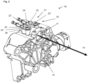
- Fig. 2 shows the assembly 16 with a component 15 designed as a flange on the hot water outlet side, a holding-down device 23 and a measuring sensor 21 designed as an electrode 22, 22'.
- the holding-down device 23 is designed in two parts and has two holding-down parts 23', 23" which are attached to the top of the housing of the component 15.
- the holding-down parts 23', 23" are each attached by a Fig. 5
- the fastening element 26 here: screw
- passing through the fastening section 23c of the hold-down parts 23', 23" shown in more detail is achieved.
- the special feature of the structure is shown by the combination of holding down measuring electrodes and their electrical contact for the transmission of measuring signals.
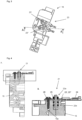
- Fig. 3 shows the assembly 16 from above.
- a sectional view through plane AA is shown in Fig. 4 shown.
- the component 15 has a cylindrical material recess extending from the surface for receiving a lower electrode section 22b and a thread extending from the same surface for fastening the hold-down device 23, 23' by means of a fastening element 26.
- electrodes 22, 22' have a thread in an upper electrode section 22a for bracing the lower electrode section 22b, which has a material projection, against the underside of the hold-down part 23', 23" by means of a locking nut 25.
- the electrodes 22, 22' which can also be referred to as measuring bolts, extend through the component 15 into the interior of the component line section 17 so that they are in contact with fluid flowing through the line 9.
- the lower electrode section 22b is provided with circumferential seals (here two O-rings).
- the measuring bolts protrude into the line 9 forming the hot water channel, for example, while in other embodiments the lines 10, 11 can also be used in the same way.
- FIG. 5 A detailed representation of a hold-down part 23', 23" with a centrally arranged hold-down section 23a and a connecting section 23b and fastening section 23c arranged on opposite sides of the hold-down section 23a for fastening the hold-down part 23', 23" by means of the fastening element 26 is shown in Fig. 5
- an annular inner edge of the opening defined by the opening engages in a ring-shaped notch arranged in an area between a lower section 22b and an upper section 22a of the electrodes 22, 22' and is supported against the notch by the elastic spring force of two spring legs extending from the inner edge of the opening into the hold-down device.
- the connecting section 23b of the holding-down parts 23', 23" is designed as an elongated flat piece for plugging into the flat plug sleeve 24.
- the connecting section 24b preferably extends against the flow direction 14 of the hot water outlet (cf. Fig. 2 ) in order, on the one hand, to keep a connected electrical cable away from heat-conducting metal pipes and, on the other hand, to guide the cable along a short route to the control device 3.
- Fig. 6 shows partial views of further embodiments of an assembly 16 according to the invention in section and from above.
- a fastening element 26 designed as a fastening bolt that engages in the component 15 in a form-fitting manner.
- the measuring sensor 21 is designed as two bolt-shaped electrodes 22, 22', one end of which protrudes into the component line section 17.
- the electrodes 22, 22' have an annular collar 22d in an area between the upper electrode section and the lower electrode section, which, together with the hold-down device 23, prevents movement of the electrodes 22, 22' in the axial direction of the electrodes.
- the flat plug sleeve 24 can be used to close an electrical connection with the control device 3 via the Fig. 6B unspecified connecting section 23b.
- Fig. 6B the fastening of the hold-down device 23 to the component 15 is achieved by the hold-down device 23 being pushed by the electrode 22, 22' into a substantially U-shaped material projection 29 provided on the component side.
- the electrode 22, 22' is designed as a measuring bolt, one end of which projects into the component line section 17.
- the electrodes 22, 22' have an upper electrode section and a lower electrode section which is wider than the upper electrode section and which can be clamped against the underside of the hold-down part 23', 23" by means of the lock nut 25, so that movement of the electrodes 22, 22' in the axial direction of the electrodes is prevented.
- the flat plug sleeve 24 can be used to close an electrical connection with the control device 3 via the in Fig. 6B unspecified connecting section 23b. It should be noted that other fastening options are also conceivable, for example a connection without screwing as in Fig. 6A conceivable.
- conductor tracks 23d for contacting electrodes 22, 22' projecting into the component line section 17 are applied to a one-piece (as a circuit board) holding-down device 23.
- the electrical contact between holding-down device 23 and electrodes 22, 22' is preferably force-fit, form-fit and/or material-fit.
- the holding-down device 23 can be screwed, clipped or latched to the component 15 by means of a fastening element 26.
- a latching plug for connection to the control device 3 can be connected to the holding-down device 23 designed as a circuit board (in Fig. 6C not shown).
- the electrodes 22, 22' can be designed as an inlay and thus form a positive and/or non-positive connection between the electrodes 22, 22' and the component 15.
- the electrodes 22, 22' can then be introduced from the fluid channel 17 towards the outside and already seal through the water pressure, so that additional sealing means can be dispensed with.
- a connection in particular a material connection, can be created by welding or soldering between the hold-down device 23 and the electrodes 22, 22' before the hold-down device 23 or the assembly of the hold-down device 23 and the electrodes 22, 22' is connected to the fluid-carrying component 15.
- the hold-down device 23 is non-metallic, in particular in the form of a circuit board, slots for tolerance compensation are then preferably provided in the circuit board.
- the electrodes 22, 22' are made of stainless steel, although higher-quality alloys are also possible. The basic requirement is that the electrodes 22, 22' are electrically conductive and, due to the water contact, corrosion-resistant.
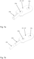
- Fig. 7A and B shows further partial views of further embodiments of the hold-down parts 23', 23", which can also be applied to other embodiments of the hold-down.
- the hold-down parts 23', 23" have a stranded wire connection in the connecting section 23b for connecting a stranded wire.
- the stranded wire of a conductor wire 22c can be connected to the connecting section 23b, for example by crimping.
- the connecting section 23b thus makes the use of a flat plug sleeve, for example, superfluous.
Landscapes
- Engineering & Computer Science (AREA)
- Physics & Mathematics (AREA)
- Chemical & Material Sciences (AREA)
- General Engineering & Computer Science (AREA)
- Mechanical Engineering (AREA)
- Combustion & Propulsion (AREA)
- Thermal Sciences (AREA)
- General Physics & Mathematics (AREA)
- Fluid Mechanics (AREA)
- Life Sciences & Earth Sciences (AREA)
- Immunology (AREA)
- Pathology (AREA)
- General Health & Medical Sciences (AREA)
- Biochemistry (AREA)
- Analytical Chemistry (AREA)
- Health & Medical Sciences (AREA)
- Electrochemistry (AREA)
- Chemical Kinetics & Catalysis (AREA)
- Instantaneous Water Boilers, Portable Hot-Water Supply Apparatuses, And Control Of Portable Hot-Water Supply Apparatuses (AREA)
- Control Of Resistance Heating (AREA)
- Investigating Or Analyzing Materials By The Use Of Electric Means (AREA)
Claims (15)
- Module de guidage de fluide (16) pour un appareil domestique (100), notamment un chauffe-eau instantané, un système d'eau chaude, une pompe à chaleur d'eau sanitaire, un petit ballon d'eau chaude, un ballon d'eau chaude mural, un ballon d'eau chaude sur socle et/ou un appareil à eau bouillante instantanée, comprenant :- un composant de guidage de fluide (15) comportant une section de conduite de composant (17) conduisant un fluide et s'étendant à travers le composant (15), laquelle section présente deux raccords disposés notamment sur des côtés opposés pour permettre un raccordement à une conduite de guidage de fluide (9, 10, 11) ;- un capteur de mesure (21) pénétrant au moins partiellement dans la section de conduite de composant (17) ;- un dispositif de retenue (23) relié de manière électriquement conductrice au capteur de mesure (21) pour transmettre un signal de mesure électrique entre le capteur de mesure (21) et un dispositif de commande (3) de l'appareil domestique (100),caractérisé en ce que
le dispositif de retenue (23) présente une première section de retenue (23a) pour retenir le capteur de mesure (21) et établir une connexion électriquement conductrice avec le capteur de mesure (21), et une première section de connexion (23b) reliée de manière électriquement conductrice à la section de retenue (23a) pour fermer une connexion électrique avec le dispositif de commande (3). - Module de guidage de fluide (16) selon la revendication 1, dans lequel le capteur de mesure (21) est configuré sous la forme d'une première électrode (22) et d'une deuxième électrode (22') espacée de la première électrode (22), et dans lequel, facultativement, la première section de retenue (23a) présente des ouvertures pour le passage des deux électrodes (22, 22').
- Module de guidage de fluide (16) selon la revendication 1 ou 2, dans lequel la première section de retenue (23a), notamment les ouvertures, et une surface d'enveloppe des électrodes (22, 22') sont adaptées l'une à l'autre de telle façon qu'il existe, entre le dispositif de retenue (23) et le capteur de mesure (21), une liaison par adhérence, par complémentarité de forme et/ou de matière.
- Module de guidage de fluide (16) selon l'une des revendications précédentes, dans lequel le dispositif de retenue (23) comprend une section de fixation (23c) et/ou le composant de guidage de fluide (15) comprend des moyens de fixation pour fixer le dispositif de retenue (23) au composant de guidage de fluide (15).
- Module de guidage de fluide (16) selon l'une des revendications précédentes 2 à 4, dans lequel le dispositif de retenue (23) est réalisé en deux parties et la première partie de retenue (23') présente la première section de retenue (23a) et la deuxième partie de retenue (23") présente une deuxième section de retenue (23a) ; la première section de retenue (23a) étant conçue pour retenir et établir une connexion électriquement conductrice avec la première électrode (22'), et la deuxième section de retenue (23a) étant conçue pour retenir et établir une connexion électriquement conductrice avec la deuxième électrode (22) et présentant une deuxième section de connexion (23b) reliée de manière électriquement conductrice à la deuxième section de retenue (23a) pour fermer une connexion électrique respective avec le dispositif de commande (3).
- Module de guidage de fluide (16) selon la revendication 5, dans lequel les deux parties de retenue (23', 23") sont réalisées à l'identique et sont notamment montées de manière inversée l'une par rapport à l'autre.
- Module de guidage de fluide (16) selon l'une des revendications précédentes 1 à 4, dans lequel le dispositif de retenue (23) est formé d'une seule pièce et comprend une deuxième section de retenue ; la première section de retenue (23a) étant configurée pour retenir et établir une connexion électriquement conductrice avec la première électrode (22), et la deuxième section de retenue (23a) étant configurée pour retenir et établir une connexion électriquement conductrice avec la deuxième électrode (22) et présentant une deuxième section de connexion (23b) reliée de manière électriquement conductrice à la deuxième section de retenue (23a) pour fermer une connexion électrique respective avec le dispositif de commande (3).
- Module de guidage de fluide (16) selon l'une des revendications précédentes, dans lequel le composant (15) est fabriqué dans un matériau non conducteur.
- Module de guidage de fluide (16) selon l'une des revendications précédentes, dans lequel le composant (15) est réalisé sous la forme d'une bride (15) qui présente, d'un côté, un raccord à une conduite (10, 11), notamment une conduite d'eau froide et/ou une conduite d'évacuation d'eau chaude, et, d'un côté opposé, un raccord à une section de conduite de chauffage (9).
- Module de guidage de fluide (16) selon l'une des revendications précédentes, dans lequel la première et/ou la deuxième section de connexion (23b) se présente sous la forme d'une pièce plate allongée, de préférence pour une connexion avec une cosse plate (24) ou un connecteur à encliquetage.
- Module de guidage de fluide (16) selon l'une des revendications 1 à 9, dans lequel la première et/ou la deuxième section de connexion (23b) sont réalisées sous la forme d'un raccord à torons.
- Module de guidage de fluide (16) selon l'une des revendications précédentes 2 à 11, dans lequel les deux électrodes (22, 22') sont formées transversalement au canal d'écoulement de la section de conduite de composant (17).
- Appareil domestique (100), en particulier un chauffe-eau instantané, un système d'eau chaude, une pompe à chaleur d'eau sanitaire, un petit ballon d'eau chaude, un ballon d'eau chaude mural, un ballon d'eau chaude sur socle et/ou un appareil à eau bouillante instantanée, comprenant :- une conduite de guidage de fluide (9, 10, 11) ;- un élément chauffant (12) s'étendant sur une section de conduite de chauffage (9) pour chauffer le fluide s'écoulant à travers la conduite (9, 10, 11) ;- un dispositif de commande (3) pour commander la puissance de chauffe de l'élément chauffant (12) pour chauffer le fluide s'écoulant à travers la conduite ; et- un module de guidage de fluide (16) selon l'une des revendications précédentes, relié à la conduite de guidage de fluide (9, 10, 11).
- Appareil domestique (100), notamment chauffe-eau instantané, selon la revendication 13, dans lequel le capteur de mesure (21) est conçu pour prélever un signal de mesure caractéristique de la conductivité du fluide s'écoulant dans la conduite de guidage de fluide (9, 10, 11), et le dispositif de commande (3) est de préférence conçu pour commander la puissance de chauffe compte tenu de cette conductivité.
- Utilisation d'un dispositif de retenue électriquement conducteur (23) pour la retenue d'un capteur de mesure (21) et la transmission d'un signal de mesure électrique entre le capteur de mesure (21), qui pénètre au moins partiellement dans une conduite de guidage de fluide (9, 10, 11) d'un dispositif domestique (100), notamment un chauffe-eau instantané, un système d'eau chaude, une pompe à chaleur d'eau sanitaire, un petit ballon d'eau chaude, un ballon d'eau chaude mural, un ballon d'eau chaude sur socle et/ou un appareil à eau bouillante instantanée, et un dispositif de commande (3) de l'appareil domestique (100),
caractérisée en ce que le dispositif de retenue (23) comprend une section de retenue (23a) pour retenir le capteur de mesure (21) et établir une connexion électriquement conductrice avec le capteur de mesure (21), et une section de connexion (23b) reliée de manière électriquement conductrice à la section de retenue (23a) pour fermer une connexion électrique avec le dispositif de commande (3).
Applications Claiming Priority (2)
| Application Number | Priority Date | Filing Date | Title |
|---|---|---|---|
| DE102019123761.0A DE102019123761B4 (de) | 2019-09-05 | 2019-09-05 | Niederhalter zum Niederhalten eines Messsensors und Weiterleiten eines elektrischen Messsignals |
| PCT/EP2020/074796 WO2021044001A1 (fr) | 2019-09-05 | 2020-09-04 | Dispositif de retenue destiné à retenir un capteur de mesure et à transmettre un signal de mesure électrique |
Publications (2)
| Publication Number | Publication Date |
|---|---|
| EP4025841A1 EP4025841A1 (fr) | 2022-07-13 |
| EP4025841B1 true EP4025841B1 (fr) | 2024-11-06 |
Family
ID=72428275
Family Applications (1)
| Application Number | Title | Priority Date | Filing Date |
|---|---|---|---|
| EP20768320.2A Active EP4025841B1 (fr) | 2019-09-05 | 2020-09-04 | Dispositif de retenue destiné à retenir un capteur de mesure et à transmettre un signal de mesure électrique |
Country Status (5)
| Country | Link |
|---|---|
| EP (1) | EP4025841B1 (fr) |
| CN (1) | CN114424072A (fr) |
| DE (1) | DE102019123761B4 (fr) |
| PL (1) | PL4025841T3 (fr) |
| WO (1) | WO2021044001A1 (fr) |
Families Citing this family (1)
| Publication number | Priority date | Publication date | Assignee | Title |
|---|---|---|---|---|
| DE102019123761B4 (de) * | 2019-09-05 | 2025-06-05 | Stiebel Eltron Gmbh & Co. Kg | Niederhalter zum Niederhalten eines Messsensors und Weiterleiten eines elektrischen Messsignals |
Family Cites Families (18)
| Publication number | Priority date | Publication date | Assignee | Title |
|---|---|---|---|---|
| DE2803951A1 (de) * | 1978-01-30 | 1979-08-02 | Stiebel Eltron Gmbh & Co Kg | Elektrischer durchlauferhitzer mit wenigstens einem blankdrahtheizkoerper |
| FR2755751B1 (fr) * | 1996-11-13 | 2002-02-15 | Bernier Jacques | Chauffe eau thermodynamique a capteur enterre |
| CN2521740Y (zh) * | 2002-01-14 | 2002-11-20 | 邵志成 | 温控器、电连接器及电热水器具 |
| US6640048B2 (en) * | 2002-03-26 | 2003-10-28 | Don Novotny | Instant water heater |
| EP1565608B1 (fr) * | 2002-11-28 | 2011-10-05 | LG Electronics, Inc. | Machine a laver, capteur de conductivite prevu dans la machine a laver et procede de commande de cette derniere |
| KR20040087177A (ko) * | 2003-04-04 | 2004-10-13 | 엘지전자 주식회사 | 수질감지센서의 전극 구조 |
| AU2003900801A0 (en) * | 2003-02-24 | 2003-03-13 | Brenton O'brien | Pcb connector |
| DE102005007935A1 (de) * | 2005-02-15 | 2006-08-24 | E.G.O. Elektro-Gerätebau GmbH | Heizeinrichtung für ein Elektrogerät |
| GB2467062B (en) * | 2006-12-06 | 2010-09-29 | Abb Ltd | Conductivity sensor |
| KR101068471B1 (ko) * | 2007-11-12 | 2011-09-29 | 주식회사 경동네트웍 | 온수시스템 및 그 제어방법 |
| DE102007056545A1 (de) * | 2007-11-23 | 2009-05-28 | Robert Bosch Gmbh | Sensoranordnung zur Bestimmung eines Tankfüllstands und Tank mit Sensoranordnung |
| CN102141514A (zh) * | 2010-12-15 | 2011-08-03 | 杭州神林电子有限公司 | 家电设备用水电导和水浊度传感器 |
| FR2994474B1 (fr) * | 2012-08-13 | 2018-06-29 | Winslim Sarl | Ensemble forme d'un chauffe-eau comportant un corps de chauffe comprenant un volume d'eau et d'au moins un generateur d'un module inductif dedie a un appareil electrique |
| CN202843344U (zh) * | 2012-10-22 | 2013-04-03 | 赖亚立 | 一种即热式饮水机 |
| DK2840404T3 (en) * | 2013-08-20 | 2016-06-27 | Gerdes Ohg | Electric blanket water heater and method for controlling the same |
| DE102014000536A1 (de) * | 2014-01-20 | 2015-07-23 | Stiebel Eltron Gmbh & Co. Kg | Verfahren und Vorrichtung zum Erfassen einer elektrischen Leitfähigkeit in einem Durchlauferhitzer |
| CN108826699A (zh) * | 2018-05-08 | 2018-11-16 | 广东万和热能科技有限公司 | 水流量传感器及具有其的电热水器防漏电装置 |
| DE102019123761B4 (de) * | 2019-09-05 | 2025-06-05 | Stiebel Eltron Gmbh & Co. Kg | Niederhalter zum Niederhalten eines Messsensors und Weiterleiten eines elektrischen Messsignals |
-
2019
- 2019-09-05 DE DE102019123761.0A patent/DE102019123761B4/de active Active
-
2020
- 2020-09-04 PL PL20768320.2T patent/PL4025841T3/pl unknown
- 2020-09-04 WO PCT/EP2020/074796 patent/WO2021044001A1/fr not_active Ceased
- 2020-09-04 CN CN202080063143.0A patent/CN114424072A/zh active Pending
- 2020-09-04 EP EP20768320.2A patent/EP4025841B1/fr active Active
Also Published As
| Publication number | Publication date |
|---|---|
| PL4025841T3 (pl) | 2025-03-17 |
| DE102019123761A1 (de) | 2021-03-11 |
| WO2021044001A1 (fr) | 2021-03-11 |
| DE102019123761B4 (de) | 2025-06-05 |
| EP4025841A1 (fr) | 2022-07-13 |
| CN114424072A (zh) | 2022-04-29 |
Similar Documents
| Publication | Publication Date | Title |
|---|---|---|
| EP2312224B1 (fr) | Pompe à chaleur dotée d'un module hydraulique | |
| EP2592982B1 (fr) | Dispositif de chauffe instantané dynamique | |
| EP4025842B1 (fr) | Chauffe-eau et procédé de commande d'un chauffe-eau | |
| EP2295886A2 (fr) | Dispositif de chauffage de liquides | |
| EP1690971A2 (fr) | Dispositif de chauffage pour un appareil électroménager | |
| DE102004054625A1 (de) | Widerstandsheizung | |
| EP1692921A1 (fr) | Dispositif de chauffage destine a des fluides, chauffe-eau instantane et leurs procedes de production | |
| DE102019123761B4 (de) | Niederhalter zum Niederhalten eines Messsensors und Weiterleiten eines elektrischen Messsignals | |
| EP3705804B1 (fr) | Appareil domestique et raccord à bride pour un tel appareil domestique | |
| EP2489951B1 (fr) | Chauffe-eau instantané électrique | |
| DE102018207112A1 (de) | Heizvorrichtung zur Erhitzung eines Fluids | |
| DE102013212725A1 (de) | Fluidführendes System mit kathodischem Korrosionsschutz | |
| EP2093515B1 (fr) | Composant partiel pour une installation de chauffage compacte | |
| EP0358843B1 (fr) | Pompes pour une installation de chauffage à eau chaude | |
| EP0630463B1 (fr) | Chauffe-eau electrique instantane | |
| EP4382811B1 (fr) | Dispositif de production de vapeur et appareil ménager à circulation d'eau doté d'un tel dispositif | |
| WO2008107053A1 (fr) | Débitmètre à tourbillons pour enregistrer la vitesse d'écoulement dans une conduite | |
| DE102004062908A1 (de) | Sensor und Verfahren zum Herstellen eines Sensors | |
| EP2439458B1 (fr) | Élément d'adaptation pour corps chauffant à visser d'un accumulateur d'eau chaude | |
| DE102006008451A1 (de) | Magnetisch-induktiver Durchflussmesser mit einem Messrohr aus Metall | |
| DE102013101792B4 (de) | Wärmepumpe | |
| DE102014215847A1 (de) | Einströmvorrichtung für einen zylindrischen Durchlauferhitzer mit Heizwendel | |
| EP3702693A1 (fr) | Régulateur de température de sécurité côté contact avec le fluide | |
| DE102018104690A1 (de) | Sensorträgereinheit sowie Heizungskomponente | |
| EP0997691B1 (fr) | Elément chauffant |
Legal Events
| Date | Code | Title | Description |
|---|---|---|---|
| STAA | Information on the status of an ep patent application or granted ep patent |
Free format text: STATUS: UNKNOWN |
|
| STAA | Information on the status of an ep patent application or granted ep patent |
Free format text: STATUS: THE INTERNATIONAL PUBLICATION HAS BEEN MADE |
|
| PUAI | Public reference made under article 153(3) epc to a published international application that has entered the european phase |
Free format text: ORIGINAL CODE: 0009012 |
|
| STAA | Information on the status of an ep patent application or granted ep patent |
Free format text: STATUS: REQUEST FOR EXAMINATION WAS MADE |
|
| 17P | Request for examination filed |
Effective date: 20220331 |
|
| AK | Designated contracting states |
Kind code of ref document: A1 Designated state(s): AL AT BE BG CH CY CZ DE DK EE ES FI FR GB GR HR HU IE IS IT LI LT LU LV MC MK MT NL NO PL PT RO RS SE SI SK SM TR |
|
| DAV | Request for validation of the european patent (deleted) | ||
| DAX | Request for extension of the european patent (deleted) | ||
| P01 | Opt-out of the competence of the unified patent court (upc) registered |
Effective date: 20230524 |
|
| GRAP | Despatch of communication of intention to grant a patent |
Free format text: ORIGINAL CODE: EPIDOSNIGR1 |
|
| STAA | Information on the status of an ep patent application or granted ep patent |
Free format text: STATUS: GRANT OF PATENT IS INTENDED |
|
| RIC1 | Information provided on ipc code assigned before grant |
Ipc: F24H 15/20 20220101ALI20240311BHEP Ipc: F24H 15/37 20220101ALI20240311BHEP Ipc: F24H 15/31 20220101ALI20240311BHEP Ipc: F24H 9/20 20060101ALI20240311BHEP Ipc: H02H 11/00 20060101ALI20240311BHEP Ipc: G01R 27/22 20060101ALI20240311BHEP Ipc: F24H 1/10 20060101AFI20240311BHEP |
|
| INTG | Intention to grant announced |
Effective date: 20240403 |
|
| GRAS | Grant fee paid |
Free format text: ORIGINAL CODE: EPIDOSNIGR3 |
|
| GRAA | (expected) grant |
Free format text: ORIGINAL CODE: 0009210 |
|
| STAA | Information on the status of an ep patent application or granted ep patent |
Free format text: STATUS: THE PATENT HAS BEEN GRANTED |
|
| AK | Designated contracting states |
Kind code of ref document: B1 Designated state(s): AL AT BE BG CH CY CZ DE DK EE ES FI FR GB GR HR HU IE IS IT LI LT LU LV MC MK MT NL NO PL PT RO RS SE SI SK SM TR |
|
| REG | Reference to a national code |
Ref country code: GB Ref legal event code: FG4D Free format text: NOT ENGLISH |
|
| REG | Reference to a national code |
Ref country code: CH Ref legal event code: EP |
|
| REG | Reference to a national code |
Ref country code: DE Ref legal event code: R096 Ref document number: 502020009703 Country of ref document: DE |
|
| REG | Reference to a national code |
Ref country code: IE Ref legal event code: FG4D Free format text: LANGUAGE OF EP DOCUMENT: GERMAN |
|
| REG | Reference to a national code |
Ref country code: LT Ref legal event code: MG9D |
|
| REG | Reference to a national code |
Ref country code: NL Ref legal event code: MP Effective date: 20241106 |
|
| PG25 | Lapsed in a contracting state [announced via postgrant information from national office to epo] |
Ref country code: PT Free format text: LAPSE BECAUSE OF FAILURE TO SUBMIT A TRANSLATION OF THE DESCRIPTION OR TO PAY THE FEE WITHIN THE PRESCRIBED TIME-LIMIT Effective date: 20250306 Ref country code: IS Free format text: LAPSE BECAUSE OF FAILURE TO SUBMIT A TRANSLATION OF THE DESCRIPTION OR TO PAY THE FEE WITHIN THE PRESCRIBED TIME-LIMIT Effective date: 20250306 Ref country code: HR Free format text: LAPSE BECAUSE OF FAILURE TO SUBMIT A TRANSLATION OF THE DESCRIPTION OR TO PAY THE FEE WITHIN THE PRESCRIBED TIME-LIMIT Effective date: 20241106 |
|
| PG25 | Lapsed in a contracting state [announced via postgrant information from national office to epo] |
Ref country code: FI Free format text: LAPSE BECAUSE OF FAILURE TO SUBMIT A TRANSLATION OF THE DESCRIPTION OR TO PAY THE FEE WITHIN THE PRESCRIBED TIME-LIMIT Effective date: 20241106 Ref country code: NL Free format text: LAPSE BECAUSE OF FAILURE TO SUBMIT A TRANSLATION OF THE DESCRIPTION OR TO PAY THE FEE WITHIN THE PRESCRIBED TIME-LIMIT Effective date: 20241106 |
|
| PG25 | Lapsed in a contracting state [announced via postgrant information from national office to epo] |
Ref country code: BG Free format text: LAPSE BECAUSE OF FAILURE TO SUBMIT A TRANSLATION OF THE DESCRIPTION OR TO PAY THE FEE WITHIN THE PRESCRIBED TIME-LIMIT Effective date: 20241106 |
|
| PG25 | Lapsed in a contracting state [announced via postgrant information from national office to epo] |
Ref country code: ES Free format text: LAPSE BECAUSE OF FAILURE TO SUBMIT A TRANSLATION OF THE DESCRIPTION OR TO PAY THE FEE WITHIN THE PRESCRIBED TIME-LIMIT Effective date: 20241106 |
|
| PG25 | Lapsed in a contracting state [announced via postgrant information from national office to epo] |
Ref country code: NO Free format text: LAPSE BECAUSE OF FAILURE TO SUBMIT A TRANSLATION OF THE DESCRIPTION OR TO PAY THE FEE WITHIN THE PRESCRIBED TIME-LIMIT Effective date: 20250206 |
|
| PG25 | Lapsed in a contracting state [announced via postgrant information from national office to epo] |
Ref country code: GR Free format text: LAPSE BECAUSE OF FAILURE TO SUBMIT A TRANSLATION OF THE DESCRIPTION OR TO PAY THE FEE WITHIN THE PRESCRIBED TIME-LIMIT Effective date: 20250207 Ref country code: LV Free format text: LAPSE BECAUSE OF FAILURE TO SUBMIT A TRANSLATION OF THE DESCRIPTION OR TO PAY THE FEE WITHIN THE PRESCRIBED TIME-LIMIT Effective date: 20241106 |
|
| PG25 | Lapsed in a contracting state [announced via postgrant information from national office to epo] |
Ref country code: RS Free format text: LAPSE BECAUSE OF FAILURE TO SUBMIT A TRANSLATION OF THE DESCRIPTION OR TO PAY THE FEE WITHIN THE PRESCRIBED TIME-LIMIT Effective date: 20250206 |
|
| PG25 | Lapsed in a contracting state [announced via postgrant information from national office to epo] |
Ref country code: SM Free format text: LAPSE BECAUSE OF FAILURE TO SUBMIT A TRANSLATION OF THE DESCRIPTION OR TO PAY THE FEE WITHIN THE PRESCRIBED TIME-LIMIT Effective date: 20241106 |
|
| PG25 | Lapsed in a contracting state [announced via postgrant information from national office to epo] |
Ref country code: DK Free format text: LAPSE BECAUSE OF FAILURE TO SUBMIT A TRANSLATION OF THE DESCRIPTION OR TO PAY THE FEE WITHIN THE PRESCRIBED TIME-LIMIT Effective date: 20241106 |
|
| PG25 | Lapsed in a contracting state [announced via postgrant information from national office to epo] |
Ref country code: EE Free format text: LAPSE BECAUSE OF FAILURE TO SUBMIT A TRANSLATION OF THE DESCRIPTION OR TO PAY THE FEE WITHIN THE PRESCRIBED TIME-LIMIT Effective date: 20241106 |
|
| PG25 | Lapsed in a contracting state [announced via postgrant information from national office to epo] |
Ref country code: RO Free format text: LAPSE BECAUSE OF FAILURE TO SUBMIT A TRANSLATION OF THE DESCRIPTION OR TO PAY THE FEE WITHIN THE PRESCRIBED TIME-LIMIT Effective date: 20241106 |
|
| PG25 | Lapsed in a contracting state [announced via postgrant information from national office to epo] |
Ref country code: SK Free format text: LAPSE BECAUSE OF FAILURE TO SUBMIT A TRANSLATION OF THE DESCRIPTION OR TO PAY THE FEE WITHIN THE PRESCRIBED TIME-LIMIT Effective date: 20241106 |
|
| PG25 | Lapsed in a contracting state [announced via postgrant information from national office to epo] |
Ref country code: CZ Free format text: LAPSE BECAUSE OF FAILURE TO SUBMIT A TRANSLATION OF THE DESCRIPTION OR TO PAY THE FEE WITHIN THE PRESCRIBED TIME-LIMIT Effective date: 20241106 |
|
| PG25 | Lapsed in a contracting state [announced via postgrant information from national office to epo] |
Ref country code: IT Free format text: LAPSE BECAUSE OF FAILURE TO SUBMIT A TRANSLATION OF THE DESCRIPTION OR TO PAY THE FEE WITHIN THE PRESCRIBED TIME-LIMIT Effective date: 20241106 |
|
| REG | Reference to a national code |
Ref country code: DE Ref legal event code: R097 Ref document number: 502020009703 Country of ref document: DE |
|
| PG25 | Lapsed in a contracting state [announced via postgrant information from national office to epo] |
Ref country code: SE Free format text: LAPSE BECAUSE OF FAILURE TO SUBMIT A TRANSLATION OF THE DESCRIPTION OR TO PAY THE FEE WITHIN THE PRESCRIBED TIME-LIMIT Effective date: 20241106 |
|
| PLBE | No opposition filed within time limit |
Free format text: ORIGINAL CODE: 0009261 |
|
| STAA | Information on the status of an ep patent application or granted ep patent |
Free format text: STATUS: NO OPPOSITION FILED WITHIN TIME LIMIT |
|
| PGFP | Annual fee paid to national office [announced via postgrant information from national office to epo] |
Ref country code: DE Payment date: 20250919 Year of fee payment: 6 |
|
| 26N | No opposition filed |
Effective date: 20250807 |
|
| PGFP | Annual fee paid to national office [announced via postgrant information from national office to epo] |
Ref country code: PL Payment date: 20250821 Year of fee payment: 6 |
|
| PGFP | Annual fee paid to national office [announced via postgrant information from national office to epo] |
Ref country code: GB Payment date: 20250919 Year of fee payment: 6 |
|
| REG | Reference to a national code |
Ref country code: CH Ref legal event code: H13 Free format text: ST27 STATUS EVENT CODE: U-0-0-H10-H13 (AS PROVIDED BY THE NATIONAL OFFICE) Effective date: 20260504 |