EP4025879B1 - Axialdurchflussmesser - Google Patents
Axialdurchflussmesser Download PDFInfo
- Publication number
- EP4025879B1 EP4025879B1 EP20781611.7A EP20781611A EP4025879B1 EP 4025879 B1 EP4025879 B1 EP 4025879B1 EP 20781611 A EP20781611 A EP 20781611A EP 4025879 B1 EP4025879 B1 EP 4025879B1
- Authority
- EP
- European Patent Office
- Prior art keywords
- flowmeter
- shaft
- impeller
- longitudinal axis
- tubular body
- Prior art date
- Legal status (The legal status is an assumption and is not a legal conclusion. Google has not performed a legal analysis and makes no representation as to the accuracy of the status listed.)
- Active
Links
Images

Classifications
-
- G—PHYSICS
- G01—MEASURING; TESTING
- G01F—MEASURING VOLUME, VOLUME FLOW, MASS FLOW OR LIQUID LEVEL; METERING BY VOLUME
- G01F1/00—Measuring the volume flow or mass flow of fluid or fluent solid material wherein the fluid passes through a meter in a continuous flow
- G01F1/05—Measuring the volume flow or mass flow of fluid or fluent solid material wherein the fluid passes through a meter in a continuous flow by using mechanical effects
- G01F1/10—Measuring the volume flow or mass flow of fluid or fluent solid material wherein the fluid passes through a meter in a continuous flow by using mechanical effects using rotating vanes with axial admission
- G01F1/115—Measuring the volume flow or mass flow of fluid or fluent solid material wherein the fluid passes through a meter in a continuous flow by using mechanical effects using rotating vanes with axial admission with magnetic or electromagnetic coupling to the indicating device
-
- G—PHYSICS
- G01—MEASURING; TESTING
- G01F—MEASURING VOLUME, VOLUME FLOW, MASS FLOW OR LIQUID LEVEL; METERING BY VOLUME
- G01F1/00—Measuring the volume flow or mass flow of fluid or fluent solid material wherein the fluid passes through a meter in a continuous flow
- G01F1/05—Measuring the volume flow or mass flow of fluid or fluent solid material wherein the fluid passes through a meter in a continuous flow by using mechanical effects
- G01F1/10—Measuring the volume flow or mass flow of fluid or fluent solid material wherein the fluid passes through a meter in a continuous flow by using mechanical effects using rotating vanes with axial admission
-
- G—PHYSICS
- G01—MEASURING; TESTING
- G01F—MEASURING VOLUME, VOLUME FLOW, MASS FLOW OR LIQUID LEVEL; METERING BY VOLUME
- G01F15/00—Details of, or accessories for, apparatus of groups G01F1/00 - G01F13/00 insofar as such details or appliances are not adapted to particular types of such apparatus
- G01F15/14—Casings, e.g. of special material
-
- G—PHYSICS
- G01—MEASURING; TESTING
- G01F—MEASURING VOLUME, VOLUME FLOW, MASS FLOW OR LIQUID LEVEL; METERING BY VOLUME
- G01F15/00—Details of, or accessories for, apparatus of groups G01F1/00 - G01F13/00 insofar as such details or appliances are not adapted to particular types of such apparatus
- G01F15/18—Supports or connecting means for meters
- G01F15/185—Connecting means, e.g. bypass conduits
Definitions
- the invention relates to an axial flowmeter, in particular for household appliances.
- the invention relates to an axial flowmeter to measure the flow rate of a fluid in a duct, which is used in hydraulic circuits of coffee machines and water dispensers, without for this reason limiting the wide range of possible applications of the invention.
- axial flowmeters in which the fluid flowing along the axis of the flowmeter causes the rotation of an impeller around said axis and a sensor detects the rotary motion of the impeller and provides signals concerning the fluid flow rate.
- documents AU 2018,260,822 , JP H0961205 and US 5,433,118 disclose respective axial flowmeters configured for measuring the flow rate of fluid in a duct.
- the correct measurement of the flow rate depends on design parameters and on the correct installation of the different components.
- the object of the invention is obviate the drawbacks of the prior art.
- an axial flowmeter to measure the flow rate of a flow of fluid in a duct comprising:
- the fluid flow determines the rotation of the impeller around the longitudinal axis.
- the fluid flow is subjected to small pressure drops when it flows through the flowmeter.
- the flowmeter comprises an identification member, which is fixed to the shaft or to the impeller and is correlated with the shape of the impeller; the tubular body being made of a transparent material.
- the flowmeter is fitted with impellers with different geometries depending on the ranges of flow rate values to be measured for which it is used, whereas the geometry of the remaining components of the flowmeter remains unchanged. Therefore, the identification member allows users to identify the flowmeter suited for a given use, even when the geometric differences between the impellers are not easily perceivable.
- the identification member it is possible to visually identify, from the outside of the tubular body, the different type of impeller present in the tubular body of the flowmeter.
- the identification member is a coloured ring.
- the impeller is at least partially made of sintered magnetic material, in particular by moulding sintered magnetic material on the shaft.
- the fluid flow rate can be measured by detecting magnetic field changes caused by the rotation of the impeller around the longitudinal axis.
- the impeller can be manufactured in a simple, quick and economic fashion.
- each central portion and the respective end portions ranges from 10° to 30°.
- first and second supports are substantially equal to one another and face one another.
- first and the second support are mounted in a symmetrical manner relative to a plane going through the centre of the flowmeter and transverse relative to the longitudinal axis.
- each one of the first and second support comprises a respective annular body; and a respective cylindrical body configured to be coupled to the respective end of the shaft.
- first and the second support can be coupled to the tubular body and the shaft can be coupled to the respective cylindrical body so as to allow the shaft to rotate around the longitudinal axis.
- each end of the shaft is tapered; each cylindrical body having a recess so as to house a respective end of the shaft.
- the shaft can be supported and, at the same time, the shaft can rotate around the longitudinal axis with no need for bearings.
- the flowmeter comprises a seat fixed to the tubular body and configured to house the sensor.
- the senor can be fixed to the tubular body.
- the senor is configured to detect the magnetic field variations caused by the rotation of the impeller around the longitudinal axis; in particular, the sensor is a Hall effect sensor.
- the senor emits electrical signals depending on the rotation speed of the impeller.
- a further object of the invention is to provide a method to manufacture a flowmeter, which reduces at least one of the drawbacks of the prior art.
- a method to manufacture an axial flowmeter to measure the flow rate of a fluid comprising:
- a flowmeter can be manufactured and assembled in a simple, quick and cost-effective fashion.
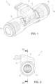
- number 1 indicates, as a whole, an axial flowmeter to measure the flow rate of a fluid inside a duct, which finds particular application in the field of household appliances.
- the flowmeter 1 is used to measure the flow rate of a fluid in hydraulic circuits of coffee machines and water dispensers, without for this reason limiting the wide range of possible applications of the invention.
- the flowmeter 1 comprises a tubular body 2 extending along a longitudinal axis A, where the fluid flow flows; a seat 3, which is fixed on the outside of the central portion of the tubular body 2; a sensor 4, which is housed in the seat 3; and two manifolds 5 and 6, which are fixed to a respective end of the tubular body 2 and are configured to connect the tubular body 2 to a respective duct.
- the flowmeter 1 comprises a shaft 7, which is arranged inside the tubular body 2 and is configured to rotate around the longitudinal axis A; two supports 8 and 9, each fixed inside the tubular body 2 and coupled to a respective end of the shaft 7; an impeller 10, which is fixed to the shaft 7; and an identification member 11, which preferably is a coloured ring and is fixed to the shaft 7.
- the tubular body 2 is made of a transparent material.
- the tubular body 2 is made of a plastic material, preferably PC or PPSU.
- the tubular body 2 has a seat in the area of each end for housing a respective manifold 5 or 6.
- the manifolds 5 and 6 are substantially equal and are arranged in the respective seat in a symmetrical manner relative a plane going through the centre of the flowmeter 1 and transverse to the longitudinal axis A.
- the supports 8 and 9 are substantially equal and face one another in a symmetrical manner relative a plane going through the centre of the flowmeter 1 and transverse to the longitudinal axis A.
- Each support 8 and 9 comprises a respective annular body 12, which is arranged around the longitudinal axis A and is configured to be fixed inside the tubular body 2; a respective cylindrical body 13, which is configured to be coupled to the respective end of the shaft 7; and four respective supports 14, which connect each annular body 12 to the respective cylindrical body 13.
- Each annular body 12 is housed in a respective annular seat obtained in the tubular body 2.
- the number of supports 14 can be different and does not limit the invention.
- Each cylindrical body 13 has a recess with a conical shape so as to be coupled to the respective end of the shaft 7.
- Each end of the shaft 7 is tapered so as to be inserted into the recess of the respective cylindrical body 13.
- the ends of the shaft 7 have a conical shape and are coupled to the recess of the respective cylindrical body 13 in order to allow the shaft 7 to rotate around the longitudinal axis A.
- the impeller 10 is made of a sintered magnetic material and is configured to rotate clockwise or counterclockwise around the longitudinal axis A depending on the direction of the fluid flow.
- the impeller 10 is configured to alternatively change its direction of rotation depending on the direction of the fluid flow.
- the sensor 4 is configured to detect the rotation speed of the impeller 10.
- the senor 4 is a Hall effect sensor, which is configured to measure the rotation speed of the impeller 10 by detecting the magnetic field variations caused by the rotation of the impeller 10 around the longitudinal axis A.
- the sensor 4 is an optical sensor, which is configured to detect the rotation speed of the impeller 10 by means of photosensors or photodetectors
- the senor 4 is an ultrasound sensor or an accelerometer, which is configured to detect the vibrations caused by the rotation of the impeller 10 around the longitudinal axis A.
- the impeller 10 is manufactured by overmoulding sintered magnetic material on the shaft 7.
- the impeller 10 comprises two vanes 15 and 16, which are arranged on opposite sides relative to the shaft 7 and each extend in a direction parallel to the longitudinal axis A.
- the vanes 15 and 16 have two respective coplanar central portions 17 and two respective end portions 18 and 19, which are inclined relative to the central portions 17.
- the central portions 17 extend along a plane P, on which the longitudinal axis A lies, and the end portions 18 and 19 are inclined relative to the plane P.
- the end portions 18 and 19 substantially have the same inclination relative to the respective central portion 17, in particular the angle between each central portion 17 and the respective end portions 18 and 19 ranges from 10° to 30°.
- the end portions 18 and 19 substantially have the same inclination relative to the plane P.
- end portion 18 of the vane 15 is adjacent to the end portion 19 of the vane 16.
- the identification member 11 is fixed in the area of an end of the impeller 10 and is configured to visually stand out from the shaft 7 and the impeller 10.
- the fluid flow flows inside the tubular body 2 and, by interacting with the vanes 15 and 16, causes the rotation of the impeller 10 around the longitudinal axis A.
- the rotation of the impeller 10 causes the sensor 4 to emit an electrical impulse when a vane 15 or 16 passes close to the sensor 4.
- the impeller 10 changes rotation direction.
- the identification member 11 allows for an immediate visual identification of the particular geometry of the impeller 10 even when the flowmeter 1 is being used.
Landscapes
- Physics & Mathematics (AREA)
- Fluid Mechanics (AREA)
- General Physics & Mathematics (AREA)
- Electromagnetism (AREA)
- Measuring Volume Flow (AREA)
- Paper (AREA)
Claims (10)
- Axialdurchflussmesser, um die Durchflussmenge eines Stroms von Fluid in einem Kanal zu messen, der Durchflussmesser (1) umfassend:- einen rohrförmigen Körper (2), der sich entlang einer Längsachse (A) erstreckt und konfiguriert ist, um das Fluid zu befördern;- eine Welle (7), die sich innerhalb des rohrförmigen Körpers (2) befindet und konfiguriert ist, um sich um die Längsachse (A) zu drehen;- eine erste und eine zweite Halterung (8, 9), die jeweils in dem rohrförmigen Körper (2) montiert sind und mit einem jeweiligen Ende der Welle (7) drehbar gekoppelt sind, um die Drehung der Welle (7) um die Längsachse (A) zu ermöglichen;- ein Laufrad (10), das an der Welle (7) befestigt ist und konfiguriert ist, um sich je nach Richtung des Stroms von Fluid im Uhrzeigersinn oder gegen den Uhrzeigersinn um die Längsachse (A) zu drehen; und- einen Sensor (4), der mit dem rohrförmigen Körper (2) gekoppelt ist und konfiguriert ist, um die Drehgeschwindigkeit des Laufrads (10) zu erfassen;wobei das Laufrad (10) nur zwei Schaufeln (15, 16) aufweist, die auf gegenüberliegenden Seiten der Welle (7) angeordnet sind, wobei der Axialdurchflussmesser dadurch gekennzeichnet ist, dass die zwei Schaufeln (15, 16) sich in eine Richtung parallel zu der Längsachse (A) erstrecken und jeweils zwei koplanare Mittelabschnitte (17) aufweisen;und dadurch, dass jede Schaufel (15, 16) zwei jeweilige Endabschnitte (18, 19) aufweist, die in Bezug auf den Mittelabschnitt (17) geneigt sind, mit im Wesentlichen der gleichen Neigung in Bezug auf den jeweiligen Mittelabschnitt (17);wobei die zwei Schaufeln (15, 16) sich entlang derselben Ebene (P) erstrecken und die geneigten Endabschnitte (18, 19) einen Anstellwinkel mit der Stromrichtung ausbilden, um die Drehung des Laufrads (10) um die Längsachse (A) je nach Richtung des Fluidstroms im Uhrzeigersinn oder gegen den Uhrzeigersinn zu erleichtern.
- Durchflussmesser nach Anspruch 1, umfassend ein Identifikationselement (11), das an der Welle (7) oder an dem Laufrad (10) befestigt ist und mit der Form des Laufrads (10) korreliert; wobei der rohrförmige Körper (2) aus einem transparenten Material hergestellt ist.
- Durchflussmesser nach Anspruch 2, wobei das Identifikationselement (11) ein farbiger Ring ist.
- Durchflussmesser nach einem der vorstehenden Ansprüche, wobei das Laufrad (10) mindestens teilweise aus gesintertem magnetischem Material hergestellt ist, insbesondere durch Formen von gesintertem magnetischem Material auf der Welle (7).
- Durchflussmesser nach einem der vorstehenden Ansprüche, wobei der Winkel zwischen jedem Mittelabschnitt (17) und den jeweiligen Endabschnitten (18, 19) zwischen 10° und 30° beträgt.
- Durchflussmesser nach einem der vorstehenden Ansprüche, wobei die erste und die zweite Halterung (8, 9) im Wesentlichen gleich zueinander sind und einander zugewandt angeordnet sind.
- Durchflussmesser nach Anspruch 6, wobei jede der ersten und der zweiten Halterung (8, 9) einen ringförmigen Körper (12); und einen jeweiligen zylindrischen Körper (13) umfasst, der konfiguriert ist, um mit dem jeweiligen Ende der Welle (7) zu koppeln.
- Durchflussmesser nach Anspruch 7, wobei jedes Ende der Welle (7) konisch ist; jeder zylindrische Körper (13) eine Aussparung aufweist, um ein jeweiliges Ende der Welle (7) unterzubringen.
- Durchflussmesser nach einem der vorstehenden Ansprüche und umfassend einen Sitz (3), der an dem rohrförmigen Körper (2) befestigt ist und konfiguriert ist, um den Sensor (4) unterzubringen.
- Durchflussmesser nach einem der Ansprüche 2 bis 9, wobei der Sensor (4) konfiguriert ist, um die Magnetfeldschwankungen, die durch die Drehung des Laufrads (10) um die Längsachse (A) verursacht werden, zu erfassen; insbesondere, der Sensor (4) ein Hall-Effekt-Sensor ist.
Priority Applications (2)
| Application Number | Priority Date | Filing Date | Title |
|---|---|---|---|
| SM20240531T SMT202400531T1 (it) | 2019-09-02 | 2020-09-02 | Flussimetro assiale |
| RS20250022A RS66389B1 (sr) | 2019-09-02 | 2020-09-02 | Aksijalni merač protoka |
Applications Claiming Priority (2)
| Application Number | Priority Date | Filing Date | Title |
|---|---|---|---|
| IT102019000015386A IT201900015386A1 (it) | 2019-09-02 | 2019-09-02 | Flussimetro assiale |
| PCT/IB2020/058172 WO2021044311A1 (en) | 2019-09-02 | 2020-09-02 | Axial flowmeter |
Publications (3)
| Publication Number | Publication Date |
|---|---|
| EP4025879A1 EP4025879A1 (de) | 2022-07-13 |
| EP4025879C0 EP4025879C0 (de) | 2024-10-30 |
| EP4025879B1 true EP4025879B1 (de) | 2024-10-30 |
Family
ID=69158214
Family Applications (1)
| Application Number | Title | Priority Date | Filing Date |
|---|---|---|---|
| EP20781611.7A Active EP4025879B1 (de) | 2019-09-02 | 2020-09-02 | Axialdurchflussmesser |
Country Status (8)
| Country | Link |
|---|---|
| EP (1) | EP4025879B1 (de) |
| ES (1) | ES3008480T3 (de) |
| HU (1) | HUE069725T2 (de) |
| IT (1) | IT201900015386A1 (de) |
| PL (1) | PL4025879T3 (de) |
| RS (1) | RS66389B1 (de) |
| SM (1) | SMT202400531T1 (de) |
| WO (1) | WO2021044311A1 (de) |
Citations (2)
| Publication number | Priority date | Publication date | Assignee | Title |
|---|---|---|---|---|
| US3880003A (en) * | 1973-11-21 | 1975-04-29 | Halliburton Co | Fluid flowmeter |
| US4232549A (en) * | 1978-12-06 | 1980-11-11 | Eaton Corporation | Two stage flowmeter |
Family Cites Families (4)
| Publication number | Priority date | Publication date | Assignee | Title |
|---|---|---|---|---|
| GB1492374A (en) * | 1973-12-06 | 1977-11-16 | Aviat Tapley Ltd | Flowmeter |
| US5433118A (en) * | 1993-12-10 | 1995-07-18 | Contadores De Agua De Zaragoza | Magnetic turbine rotor for low flow fluid meter |
| JPH0961205A (ja) * | 1995-08-28 | 1997-03-07 | Paloma Ind Ltd | 流量センサー |
| AU2018260822A1 (en) * | 2017-11-06 | 2019-05-23 | Gallagher Group Limited | A Visual Flow Indicator |
-
2019
- 2019-09-02 IT IT102019000015386A patent/IT201900015386A1/it unknown
-
2020
- 2020-09-02 WO PCT/IB2020/058172 patent/WO2021044311A1/en not_active Ceased
- 2020-09-02 PL PL20781611.7T patent/PL4025879T3/pl unknown
- 2020-09-02 EP EP20781611.7A patent/EP4025879B1/de active Active
- 2020-09-02 ES ES20781611T patent/ES3008480T3/es active Active
- 2020-09-02 SM SM20240531T patent/SMT202400531T1/it unknown
- 2020-09-02 RS RS20250022A patent/RS66389B1/sr unknown
- 2020-09-02 HU HUE20781611A patent/HUE069725T2/hu unknown
Patent Citations (2)
| Publication number | Priority date | Publication date | Assignee | Title |
|---|---|---|---|---|
| US3880003A (en) * | 1973-11-21 | 1975-04-29 | Halliburton Co | Fluid flowmeter |
| US4232549A (en) * | 1978-12-06 | 1980-11-11 | Eaton Corporation | Two stage flowmeter |
Also Published As
| Publication number | Publication date |
|---|---|
| EP4025879C0 (de) | 2024-10-30 |
| ES3008480T3 (en) | 2025-03-24 |
| EP4025879A1 (de) | 2022-07-13 |
| WO2021044311A1 (en) | 2021-03-11 |
| IT201900015386A1 (it) | 2021-03-02 |
| SMT202400531T1 (it) | 2025-01-14 |
| PL4025879T3 (pl) | 2025-02-24 |
| HUE069725T2 (hu) | 2025-04-28 |
| RS66389B1 (sr) | 2025-02-28 |
Similar Documents
| Publication | Publication Date | Title |
|---|---|---|
| US6487919B1 (en) | Turbine flow monitoring device | |
| EP3139137B1 (de) | Flüssigkeitsflussmesser | |
| JP2015521746A (ja) | 流量計 | |
| KR101423048B1 (ko) | 터빈 유량계 | |
| EP4025879B1 (de) | Axialdurchflussmesser | |
| US10634529B2 (en) | Flow measuring device having a diffuser with plural passages for directing flow toward the impeller vanes | |
| JP5043245B1 (ja) | 流量センサ | |
| EP3173748B1 (de) | Vorrichtung zur volumetrischen messung und/oder reglung des durchflusses | |
| EA044467B1 (ru) | Осевой расходомер | |
| CN201210062Y (zh) | 带有导流翼片和逆转防止装置的液体流量传感器 | |
| US20150362349A1 (en) | Throughflow measurement device for a beverage preparation machine | |
| KR100569815B1 (ko) | 터빈유량계 | |
| JP2005257309A (ja) | タービン流量計及び流体回転機械 | |
| KR20020076418A (ko) | 터빈 유량계 | |
| KR100400405B1 (ko) | 터빈 유량계 | |
| EP1464927A2 (de) | Durchflussmesser mit magnetischem Sensor | |
| CN220206749U (zh) | 一种转子装置以及具有其的流量传感器、球阀 | |
| KR200260589Y1 (ko) | 유량감지기 | |
| CN223710729U (zh) | 流量传感器及热水器 | |
| KR200355845Y1 (ko) | 터빈유량계 | |
| KR102690552B1 (ko) | 회전체 구동 방식 유량계 | |
| KR101458109B1 (ko) | 유량 검출 장치 | |
| EP4067831B1 (de) | Gerät zur erkennung eines flüssigkeitsflusses in einem haushaltsgerät | |
| CN212620895U (zh) | 一种叶轮、检测组件及流量计 | |
| KR20260003924A (ko) | 미소유량 측정이 가능한 터빈 유량계 |
Legal Events
| Date | Code | Title | Description |
|---|---|---|---|
| STAA | Information on the status of an ep patent application or granted ep patent |
Free format text: STATUS: UNKNOWN |
|
| STAA | Information on the status of an ep patent application or granted ep patent |
Free format text: STATUS: THE INTERNATIONAL PUBLICATION HAS BEEN MADE |
|
| PUAI | Public reference made under article 153(3) epc to a published international application that has entered the european phase |
Free format text: ORIGINAL CODE: 0009012 |
|
| STAA | Information on the status of an ep patent application or granted ep patent |
Free format text: STATUS: REQUEST FOR EXAMINATION WAS MADE |
|
| 17P | Request for examination filed |
Effective date: 20220325 |
|
| AK | Designated contracting states |
Kind code of ref document: A1 Designated state(s): AL AT BE BG CH CY CZ DE DK EE ES FI FR GB GR HR HU IE IS IT LI LT LU LV MC MK MT NL NO PL PT RO RS SE SI SK SM TR |
|
| DAX | Request for extension of the european patent (deleted) | ||
| RAV | Requested validation state of the european patent: fee paid |
Extension state: TN Effective date: 20220325 Extension state: MD Effective date: 20220325 Extension state: MA Effective date: 20220325 |
|
| P01 | Opt-out of the competence of the unified patent court (upc) registered |
Effective date: 20230418 |
|
| GRAP | Despatch of communication of intention to grant a patent |
Free format text: ORIGINAL CODE: EPIDOSNIGR1 |
|
| STAA | Information on the status of an ep patent application or granted ep patent |
Free format text: STATUS: GRANT OF PATENT IS INTENDED |
|
| INTG | Intention to grant announced |
Effective date: 20240430 |
|
| GRAS | Grant fee paid |
Free format text: ORIGINAL CODE: EPIDOSNIGR3 |
|
| GRAA | (expected) grant |
Free format text: ORIGINAL CODE: 0009210 |
|
| STAA | Information on the status of an ep patent application or granted ep patent |
Free format text: STATUS: THE PATENT HAS BEEN GRANTED |
|
| AK | Designated contracting states |
Kind code of ref document: B1 Designated state(s): AL AT BE BG CH CY CZ DE DK EE ES FI FR GB GR HR HU IE IS IT LI LT LU LV MC MK MT NL NO PL PT RO RS SE SI SK SM TR |
|
| REG | Reference to a national code |
Ref country code: GB Ref legal event code: FG4D |
|
| REG | Reference to a national code |
Ref country code: CH Ref legal event code: EP |
|
| REG | Reference to a national code |
Ref country code: DE Ref legal event code: R096 Ref document number: 602020040382 Country of ref document: DE |
|
| REG | Reference to a national code |
Ref country code: IE Ref legal event code: FG4D |
|
| U01 | Request for unitary effect filed |
Effective date: 20241107 |
|
| P04 | Withdrawal of opt-out of the competence of the unified patent court (upc) registered |
Free format text: CASE NUMBER: APP_60849/2024 Effective date: 20241112 |
|
| U07 | Unitary effect registered |
Designated state(s): AT BE BG DE DK EE FI FR IT LT LU LV MT NL PT RO SE SI Effective date: 20241115 |
|
| REG | Reference to a national code |
Ref country code: SK Ref legal event code: T3 Ref document number: E 45699 Country of ref document: SK |
|
| REG | Reference to a national code |
Ref country code: GR Ref legal event code: EP Ref document number: 20250400016 Country of ref document: GR Effective date: 20250211 |
|
| REG | Reference to a national code |
Ref country code: ES Ref legal event code: FG2A Ref document number: 3008480 Country of ref document: ES Kind code of ref document: T3 Effective date: 20250324 |
|
| PG25 | Lapsed in a contracting state [announced via postgrant information from national office to epo] |
Ref country code: IS Free format text: LAPSE BECAUSE OF FAILURE TO SUBMIT A TRANSLATION OF THE DESCRIPTION OR TO PAY THE FEE WITHIN THE PRESCRIBED TIME-LIMIT Effective date: 20250228 Ref country code: HR Free format text: LAPSE BECAUSE OF FAILURE TO SUBMIT A TRANSLATION OF THE DESCRIPTION OR TO PAY THE FEE WITHIN THE PRESCRIBED TIME-LIMIT Effective date: 20241030 |
|
| REG | Reference to a national code |
Ref country code: HU Ref legal event code: AG4A Ref document number: E069725 Country of ref document: HU |
|
| VS25 | Lapsed in a validation state [announced via postgrant information from nat. office to epo] |
Ref country code: MD Free format text: LAPSE BECAUSE OF FAILURE TO SUBMIT A TRANSLATION OF THE DESCRIPTION OR TO PAY THE FEE WITHIN THE PRESCRIBED TIME-LIMIT Effective date: 20241030 |
|
| PLBE | No opposition filed within time limit |
Free format text: ORIGINAL CODE: 0009261 |
|
| STAA | Information on the status of an ep patent application or granted ep patent |
Free format text: STATUS: NO OPPOSITION FILED WITHIN TIME LIMIT |
|
| U20 | Renewal fee for the european patent with unitary effect paid |
Year of fee payment: 6 Effective date: 20250814 |
|
| REG | Reference to a national code |
Ref country code: CH Ref legal event code: U11 Free format text: ST27 STATUS EVENT CODE: U-0-0-U10-U11 (AS PROVIDED BY THE NATIONAL OFFICE) Effective date: 20251001 |
|
| PGFP | Annual fee paid to national office [announced via postgrant information from national office to epo] |
Ref country code: SM Payment date: 20250923 Year of fee payment: 6 |
|
| 26N | No opposition filed |
Effective date: 20250731 |
|
| PGFP | Annual fee paid to national office [announced via postgrant information from national office to epo] |
Ref country code: GR Payment date: 20250923 Year of fee payment: 6 Ref country code: NO Payment date: 20250917 Year of fee payment: 6 |
|
| PGFP | Annual fee paid to national office [announced via postgrant information from national office to epo] |
Ref country code: TR Payment date: 20250812 Year of fee payment: 6 Ref country code: PL Payment date: 20250819 Year of fee payment: 6 |
|
| PGFP | Annual fee paid to national office [announced via postgrant information from national office to epo] |
Ref country code: HU Payment date: 20250822 Year of fee payment: 6 Ref country code: GB Payment date: 20250923 Year of fee payment: 6 |
|
| PGFP | Annual fee paid to national office [announced via postgrant information from national office to epo] |
Ref country code: RS Payment date: 20250812 Year of fee payment: 6 Ref country code: CZ Payment date: 20250814 Year of fee payment: 6 |
|
| PGFP | Annual fee paid to national office [announced via postgrant information from national office to epo] |
Ref country code: SK Payment date: 20250815 Year of fee payment: 6 |
|
| PGFP | Annual fee paid to national office [announced via postgrant information from national office to epo] |
Ref country code: CH Payment date: 20251001 Year of fee payment: 6 |
|
| PGFP | Annual fee paid to national office [announced via postgrant information from national office to epo] |
Ref country code: ES Payment date: 20251015 Year of fee payment: 6 |
|
| VS25 | Lapsed in a validation state [announced via postgrant information from nat. office to epo] |
Ref country code: MA Free format text: LAPSE BECAUSE OF FAILURE TO SUBMIT A TRANSLATION OF THE DESCRIPTION OR TO PAY THE FEE WITHIN THE PRESCRIBED TIME-LIMIT; INVALID AB INITIO Effective date: 20200902 |