EP4026152B1 - Vakuumschaltvorrichtung für eine schaltung mit haupt- und nebenstrompfad - Google Patents
Vakuumschaltvorrichtung für eine schaltung mit haupt- und nebenstrompfad Download PDFInfo
- Publication number
- EP4026152B1 EP4026152B1 EP20789874.3A EP20789874A EP4026152B1 EP 4026152 B1 EP4026152 B1 EP 4026152B1 EP 20789874 A EP20789874 A EP 20789874A EP 4026152 B1 EP4026152 B1 EP 4026152B1
- Authority
- EP
- European Patent Office
- Prior art keywords
- electrical contact
- housing body
- switching device
- vacuum switching
- section
- Prior art date
- Legal status (The legal status is an assumption and is not a legal conclusion. Google has not performed a legal analysis and makes no representation as to the accuracy of the status listed.)
- Active
Links
Images


Classifications
-
- H—ELECTRICITY
- H01—ELECTRIC ELEMENTS
- H01H—ELECTRIC SWITCHES; RELAYS; SELECTORS; EMERGENCY PROTECTIVE DEVICES
- H01H33/00—High-tension or heavy-current switches with arc-extinguishing or arc-preventing means
- H01H33/60—Switches wherein the means for extinguishing or preventing the arc do not include separate means for obtaining or increasing flow of arc-extinguishing fluid
- H01H33/66—Vacuum switches
- H01H33/662—Housings or protective screens
-
- H—ELECTRICITY
- H01—ELECTRIC ELEMENTS
- H01H—ELECTRIC SWITCHES; RELAYS; SELECTORS; EMERGENCY PROTECTIVE DEVICES
- H01H33/00—High-tension or heavy-current switches with arc-extinguishing or arc-preventing means
- H01H33/60—Switches wherein the means for extinguishing or preventing the arc do not include separate means for obtaining or increasing flow of arc-extinguishing fluid
- H01H33/66—Vacuum switches
- H01H33/662—Housings or protective screens
- H01H33/66261—Specific screen details, e.g. mounting, materials, multiple screens or specific electrical field considerations
-
- H—ELECTRICITY
- H01—ELECTRIC ELEMENTS
- H01H—ELECTRIC SWITCHES; RELAYS; SELECTORS; EMERGENCY PROTECTIVE DEVICES
- H01H1/00—Contacts
- H01H1/50—Means for increasing contact pressure, preventing vibration of contacts, holding contacts together after engagement, or biasing contacts to the open position
-
- H—ELECTRICITY
- H01—ELECTRIC ELEMENTS
- H01H—ELECTRIC SWITCHES; RELAYS; SELECTORS; EMERGENCY PROTECTIVE DEVICES
- H01H33/00—High-tension or heavy-current switches with arc-extinguishing or arc-preventing means
- H01H33/02—Details
- H01H33/04—Means for extinguishing or preventing arc between current-carrying parts
- H01H33/12—Auxiliary contacts on to which the arc is transferred from the main contacts
- H01H33/121—Load break switches
- H01H33/125—Load break switches comprising a separate circuit breaker
-
- H—ELECTRICITY
- H01—ELECTRIC ELEMENTS
- H01H—ELECTRIC SWITCHES; RELAYS; SELECTORS; EMERGENCY PROTECTIVE DEVICES
- H01H33/00—High-tension or heavy-current switches with arc-extinguishing or arc-preventing means
- H01H33/60—Switches wherein the means for extinguishing or preventing the arc do not include separate means for obtaining or increasing flow of arc-extinguishing fluid
- H01H33/66—Vacuum switches
- H01H33/662—Housings or protective screens
- H01H33/66207—Specific housing details, e.g. sealing, soldering or brazing
-
- H—ELECTRICITY
- H01—ELECTRIC ELEMENTS
- H01H—ELECTRIC SWITCHES; RELAYS; SELECTORS; EMERGENCY PROTECTIVE DEVICES
- H01H33/00—High-tension or heavy-current switches with arc-extinguishing or arc-preventing means
- H01H33/60—Switches wherein the means for extinguishing or preventing the arc do not include separate means for obtaining or increasing flow of arc-extinguishing fluid
- H01H33/66—Vacuum switches
- H01H33/664—Contacts; Arc-extinguishing means, e.g. arcing rings
-
- H—ELECTRICITY
- H01—ELECTRIC ELEMENTS
- H01H—ELECTRIC SWITCHES; RELAYS; SELECTORS; EMERGENCY PROTECTIVE DEVICES
- H01H33/00—High-tension or heavy-current switches with arc-extinguishing or arc-preventing means
- H01H33/60—Switches wherein the means for extinguishing or preventing the arc do not include separate means for obtaining or increasing flow of arc-extinguishing fluid
- H01H33/66—Vacuum switches
- H01H33/666—Operating arrangements
- H01H33/6661—Combination with other type of switch, e.g. for load break switches
-
- H—ELECTRICITY
- H01—ELECTRIC ELEMENTS
- H01H—ELECTRIC SWITCHES; RELAYS; SELECTORS; EMERGENCY PROTECTIVE DEVICES
- H01H33/00—High-tension or heavy-current switches with arc-extinguishing or arc-preventing means
- H01H33/60—Switches wherein the means for extinguishing or preventing the arc do not include separate means for obtaining or increasing flow of arc-extinguishing fluid
- H01H33/66—Vacuum switches
- H01H33/662—Housings or protective screens
- H01H33/66238—Specific bellows details
- H01H2033/66246—Details relating to the guiding of the contact rod in vacuum switch belows
Definitions
- the present invention relates to a vacuum switching device, in particular a vacuum interrupter, and a circuit with a main current path and a secondary current path parallel thereto, wherein a vacuum switching device is arranged in the secondary current path.
- Fig. 9 shows a conventional vacuum switching device in the form of a vacuum switching tube.
- the conventional vacuum switching device has a housing body which comprises an electrically insulating material such as a ceramic tube, a stationary electrical contact which is arranged stationary with respect to the housing body and within the housing body, and a movable electrical contact which is arranged movable with respect to the housing body and within the housing body such that it makes electrical contact with the stationary electrical contact when it moves towards it and breaks the electrical contact when it moves away from the stationary electrical contact.
- Vacuum interrupters must meet application-specific technical requirements during operation, particularly with regard to external dielectric strength. Due to the manufacturing process, a metallization edge or solder edge is present at the axial end of the ceramic tube, which is considered a potential weak point for the external dielectric strength U. In order to meet the external dielectric strength requirement in the application environment, different design features on the tube (including installation situation) or insulation options (gas, oil, silicone, etc.) can be used. On the one hand A sufficient dielectric strength can be generated by sufficiently dimensioning the ceramic length in air or by using gaseous insulating media such as SF6 (or other technical gases, even with increased pressure compared to the atmosphere). Other conventional measures include siliconizing entire tubes or partially insulating the metallization edge, e.g. using Pottband.
- Another requirement for the tube is a sufficient contact pressure force between the stationary electrical contact and the movable electrical contact.
- the current-carrying contacts of the vacuum switching device are kept closed by external forces. These forces consist of the closing force due to the pressure difference from the inside to the outside and additional closing forces introduced from the outside, which are often implemented by springs (figs + spring). The forces prevent the contacts from lifting at high currents and reduce the internal resistance of the current path. In particular, in applications in which only small currents have to be controlled, only small contact pressure forces are required due to the quadratic dependence on the current. If the inherent closing force of the tube itself is relatively small and also fluctuates due to component tolerances, defined conditions are created by additional forces applied from the outside.
- the contact forces for vacuum interrupters are usually generated outside the tube in corresponding spring assemblies.
- a vacuum interrupter which has a moving contact guided in a bearing which is arranged to be movable by means of a bellows.
- the US2,981,813 discloses a vacuum switch in which the moving contact bolt is guided in a bearing in a bellows.
- the EP 2479 769 A1 shows a switching device with a main current path and a secondary current path with a vacuum switch.
- the EP 3 109 878 A1 discloses a vacuum interrupter with a bearing and a spring arrangement acting on the moving contact.
- a vacuum switching device has a housing body comprising an electrically insulating material, a stationary electrical contact which is arranged stationary with respect to the housing body and within the housing body, a movable electrical contact which is arranged movable with respect to the housing body and within the housing body such that it makes electrical contact with the stationary electrical contact when moving toward it and breaks the electrical contact when moving away from the stationary electrical contact, and a sliding bearing which is connected to the housing body and slidably supports the movable electrical contact for its movement toward and away from the stationary electrical contact.
- the sliding bearing comprises an electrically conductive material and shields the Housing body at least partially dielectrically.
- the plain bearing has a spring support on which a spring element is supported, which presses the movable electrical contact in the direction of the stationary electrical contact.
- the plain bearing takes on a variety of functions, namely not only the plain bearing of the movable electrical contact, but also the function of dielectric control of the metallization edge and the counter bearing of the spring element (integrated, for example, in a bellows space) for building up the contact force.
- the housing body has a flange at one of its axial ends, which has an electrically conductive material, whereby the plain bearing at least partially electrically shields the flange.
- the plain bearing made of electrically conductive material also takes on the function of dielectric control of the metallization edge by homogenizing the electrical field in the area of the metallization edge in such a way that the dielectric strength can be increased there.
- the sliding bearing also has a tubular sliding section that is coaxially slidably mounted on the shaft section of the movable electrical contact, and a shielding section that extends radially outward from the sliding section and at least partially electrically shields the flange of the housing body as well as the soldering edge. This also results in a particularly compact design.
- the shield section of the plain bearing has at least one spirally extending slot.
- the movable electrical contact has a contact section and an axial shaft section connected thereto, and the spring element is placed coaxially on the shaft section and pre-tensioned between the spring support of the sliding bearing and another spring support of the movable electrical contact.
- the plain bearing is attached to the housing body by a bayonet lock, a snap lock, an adhesive connection or a thread.
- the bayonet lock, the snap lock, the adhesive connection or the thread is provided on the sliding section of the plain bearing.
- the shield section of the sliding bearing is axially inclined towards the housing body. According to one embodiment, the shield section is arranged at an axial end of the sliding section. This achieves a compact design and at the same time an effective dielectric control.
- the shield section of the plain bearing has a stop that is intended to center the plain bearing in its installed state and to support it axially. This means that a further function is integrated in the plain bearing, namely the reception and centering of the plain bearing and/or the housing body in the vacuum switching device.
- the shield section is elastically deformable in the axial direction (for example through the spirally extending slot). Due to the resilient The design of the shield section enables installation in an undercut and also ensures that the outer shield section always rests on the solder edge and reliably deflects it.
- the counterforce of the spring element is transmitted via the plain bearing to the shield section of the plain bearing and from there transferred to an external receiving body.
- the vacuum switching device further comprises a bellows which is arranged coaxially above the spring element and coaxially above the tubular sliding portion of the sliding bearing and is connected to the movable electrical contact on the one hand and the housing body on the other hand.
- the vacuum switching device is a vacuum interrupter.
- the shaft portion of the movable electrical contact projects axially beyond the sliding bearing and has a coupling portion at its axial end to which an external actuating element such as a rocker can be coupled in order to move the movable electrical contact toward or away from the stationary electrical contact.
- a circuit is provided with a main current path and a secondary current path parallel thereto, wherein a vacuum switching device is arranged in the secondary current path, wherein the vacuum switching device is an embodiment of the first aspect of the invention described above, which comprises: a housing body comprising an electrically insulating material; a stationary electrical contact which is arranged stationary with respect to the housing body and within the housing body; a movable electrical contact which is arranged movable with respect to the housing body and within the housing body such that it is its movement towards the stationary electrical contact makes electrical contact with the latter and its movement away from the stationary electrical contact breaks the electrical contact; and a spring element which presses the movable electrical contact towards the stationary electrical contact.
- the vacuum switching device has a bellows which is arranged coaxially around the spring element or which is formed by the spring element.
- the vacuum switching device is an embodiment of the first aspect of the invention described above.
- a stroke of the movable electrical contact is 4 to 20 mm, preferably 6 to 10 mm; a load breaking current in the secondary current path is less than 1250 A, preferably 630 A ⁇ 30 A; a current flow duration during a switching off process of the vacuum switching device is 1 to 20 ms; the circuit is used in a voltage range that is greater than or equal to 1 kV, preferably in a range between 1 kV and 52 kV inclusive; a takeover current in a load-break switch-fuse combination in the secondary current path is less than 2500 A; a spring constant of the spring element is in a range between 1 and 15 N/mm inclusive.
- the present invention uses a vacuum switching device for use in a bypass current path.
- the spring element used serves as a mechanical support. It is comparatively weak and compact. Therefore, the spring element can be arranged within a bellows for use in a vacuum interrupter.
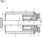
- Fig. 1 shows a longitudinal section through a vacuum switching device 1 according to an embodiment of the present invention.
- the vacuum switching device 1 is a vacuum switching tube and has a cylindrical housing body 2, which has an electrically insulating material or is made of an electrically insulating material.
- the electrically insulating material can be a ceramic.
- the electrically insulating material can be formed by a tube, as in the illustrated embodiment in particular by a cylindrical ceramic tube 19.
- Within the Housing body 2 contains a stationary electrical contact 3 which is arranged stationary with respect to housing body 2, and a movable electrical contact 4 which is arranged movable with respect to housing body 2 such that when it moves toward the stationary electrical contact 3 it makes electrical contact with it and when it moves away from the stationary electrical contact 3 it breaks the electrical contact.
- the vacuum switching device 1 further has a sliding bearing 5 which is connected to the housing body 2 and which slidingly supports the movable electrical contact 4 for its movement to and from the stationary electrical contact 3.
- the sliding bearing 5 has an electrically conductive material or is made of an electrically conductive material and at least partially electrically shields the housing body 2.
- a spring support 6 is provided on the sliding bearing 5, on which a spring element 7 in the form of a compression spring is supported, which presses the movable electrical contact 4 in the direction of the stationary electrical contact 3.
- the spring element 7 is placed coaxially on the shaft section 10 and is prestressed between the spring support 6 of the sliding bearing 5 and a further spring support 11 of the movable electrical contact 4.
- the movable electrical contact 4 has a contact section 9 and an axial shaft section 10 connected thereto.
- the housing body 2 has at one of its axial ends (at the right end in the Fig. 1 ) a flange 8 which comprises an electrically conductive material or which is formed from an electrically conductive material, wherein the plain bearing 5 at least partially electrically shields the flange 8.
- the housing body 2 further has at its other axial end (at the left end in the Fig. 1 ) a further flange 18 which has an electrically conductive material or which is formed from an electrically conductive material
- the housing body 2 is therefore formed by the cylindrical ceramic tube 19, the flange 8 and the further flange 18.
- the shaft portion 10 of the movable electrical contact 4 projects axially beyond the plain bearing 5 and has at its axial end a coupling portion 16 to which an external actuating element such as a rocker can be coupled in order to move the movable electrical contact 4 toward or away from the stationary electrical contact 3.
- the sliding bearing 5 has a tubular sliding portion 12 which is coaxially slidably mounted on the shaft portion 10 of the movable electrical contact 4, and a shielding portion 13 which extends radially outward from the sliding portion 12 and at least partially electrically shields the flange 8 of the housing body 2.
- the plain bearing 5 and in particular its shielding section 5 ensure dielectric control or smoothing of the electric field in the area of the metallization edge, so that the dielectric strength can be significantly improved there.
- the vacuum switching device 1 further has a bellows 15 which is arranged coaxially above the spring element 7 and coaxially above the tubular sliding section 12 of the sliding bearing 5 and is connected to the movable electrical contact 4 on the one hand and the housing body 2 (ie the flange 8) on the other.
- the bellows 15 is protected by a pot-shaped shield 17 arranged on the movable electrical contact 4.
- the spring element 7 does not necessarily have to be designed as a separate compression spring.
- the bellows 15 can additionally take on the function and property of the spring element 7.
- the spring element 7 and the sliding bearing 5 can be designed as one piece, wherein the spring support 6 can be implemented, for example, by a material, form-fitting or force-fitting coupling between the spring element 7 and the sliding bearing 5.
- the shield portion 13 of the sliding bearing 5 is arranged at an axial end of the sliding portion 12, and is axially inclined toward the housing body 2.
- a plurality of spirally extending slots 14 are formed in the shield portion 13 of the sliding bearing 5, so that the shield portion 13 is elastically deformable in the axial and radial directions.
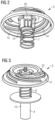
- Fig. 2 shows a perspective view of an assembly consisting of the plain bearing 5 and the spring element 7 according to the embodiment.
- Fig. 2 shows in particular the spring support 6 for the spring element 7, the sliding section 12, the shield section 13 and the plurality of slots 14 in the shield section 13 of the sliding bearing 5.
- the Fig. 2 also shows a bayonet catch 20, by means of which the plain bearing 5 is attached to the housing body 2.
- the bayonet catch 20 is formed on an outer surface of the sliding section 12 and engages with a complementary inner contour of the flange 8.
- the sliding section 12 of the plain bearing 5 is introduced into a central through-opening in the flange 8, and by rotating the plain bearing 5, the bayonet catch 20 engages or closes the bayonet catch 20.
- Fig. 3 shows a perspective view of an assembly consisting of the plain bearing 5, the spring element 7, the movable electrical contact 4, which has the contact section 9 and the shaft section 10, and the shield 17 according to the embodiment.
- the slots 14 in the shield section 13 of the plain bearing 5 are also shown.
- Fig. 4 shows a perspective view of an assembly consisting of the ceramic tube 19, the flange 8 and the movable electrical contact 4.
- the shaft section 10 of the movable electrical contact 4 projects axially beyond the plain bearing 5 located behind the flange 8 (not shown in the Fig. 4 shown) and has at its axial end the coupling section 16 to which the external actuating element such as the rocker can be coupled in order to move the movable electrical contact 4 towards or away from the stationary electrical contact 3.
- Fig. 5 shows a perspective view of an assembly consisting of the flange 8 located behind the plain bearing 5, the movable electrical contact 4 and the plain bearing 5.
- the Fig. 5 shows in comparison with the Fig. 4 the state in which the plain bearing 5 is arranged above the flange 8.
- Figures 6 and 7 each show perspective longitudinal sections through the vacuum switching device 1 according to the embodiment of the present invention.
- the various components and functions of the sliding bearing 5 are indicated again.
- the reference symbol A designates the bearing function for the sliding bearing of the movable electrical contact 4 by the sliding section 12 of the sliding bearing 5.
- the reference symbol B designates the function of the sliding bearing 5 for dielectric control or for smoothing the electrical field by means of the shielding section 13, which shields the metallization edge or solder edge of the housing body 2.
- the reference symbol C designates the function for centering the plain bearing 5 already mentioned above.
- the centering is effected by a stop 22.
- the stop 22 is formed by a raised, ring-shaped contour of the shield section 13 and engages in a complementary Recess of an external receiving body 21 according to the tongue and groove principle.
- the arrow marked with the reference symbol D shows the force flow of the spring force of the spring element 7 between the stop 22 and the further spring support 11 formed on the movable electrical contact 4.
- the arrow marked with the reference symbol E shows the force flow of a force between the flange 8 and the contact section 9. This force is made up of a bellows force applied by the bellows 15 and a gas pressure difference force applied from the outside.
- Fig. 8 shows an equivalent circuit diagram of a circuit 100 with a main current path 30 and a secondary current path 40 parallel thereto, wherein a vacuum switching device 1 is arranged in the secondary current path 40.
- the main current path 30 and the secondary current path 40 each have a common node P at one end, which is connected to a first line 60.
- the other ends of the main current path 30 and the secondary current path 40 can be optionally connected to a second line 70 via a switching device 50.
- the Fig. 1 shown vacuum switching device 1 can be arranged in the bypass current path.
- a vacuum switching device 1 has a housing body 2, which has an electrically insulating material, a stationary electrical contact 3, which is arranged stationary with respect to the housing body 2 and within the housing body 2, a movable electrical contact 4, which is arranged movable with respect to the housing body 2 and within the housing body 2 such that it makes electrical contact with the stationary electrical contact 3 when it moves towards it and breaks the electrical contact when it moves away from the stationary electrical contact 3, and a spring element 7, which presses the movable electrical contact 4 towards the stationary electrical contact 3.
- the spring element 7 is preferably designed as a compression spring.
- the vacuum switching device 1 can have a bellows 15 which is arranged coaxially around the spring element 7.
- the bellows can be formed by the spring element 7 itself.
- a stroke of the movable electrical contact 4 is 4 to 20 mm, preferably 6 to 10 mm; a load breaking current in the secondary current path 40 is less than 1250 A, preferably 630 A ⁇ 30 A; a current flow duration during a switching off process of the vacuum switching device 1 is 1 to 20 ms; the circuit 100 is used in a voltage range that is greater than or equal to 1 kV, preferably in a range between 1 kV and 52 kV inclusive; a spring constant of the spring element is in a range between 1 and 15 N/mm inclusive; a takeover current in a load break switch-fuse combination in the secondary current path 40 is less than 2500 A.
- a fuse such as a fuse can be arranged in series with the vacuum switching device 1 in the second line 70.
- the fuse can be arranged at the output of the vacuum switching device 1.
- the fuse in turn can be connected, for example, to a transformer which is connected to the output of the second line 70.
Landscapes
- High-Tension Arc-Extinguishing Switches Without Spraying Means (AREA)
Description
- Die vorliegende Erfindung betrifft eine Vakuumschaltvorrichtung, insbesondere eine Vakuumschaltröhre, und eine Schaltung mit einem Hauptstrompfad und einem dazu parallelen Nebenstrompfad, wobei in dem Nebenstrompfad eine Vakuumschaltvorrichtung angeordnet ist.
-
Fig. 9 zeigt eine konventionelle Vakuumschaltvorrichtung in Gestalt einer Vakuumschaltröhre. Die konventionelle Vakuumschaltvorrichtung hat einen Gehäusekörper, der ein elektrisch isolierendes Material wie zum Beispiel eine Keramikröhre aufweist, einen ortsfesten elektrischen Kontakt, der ortsfest bezüglich des Gehäusekörpers und innerhalb des Gehäusekörpers angeordnet ist, und einen beweglichen elektrischen Kontakt, der beweglich bezüglich des Gehäusekörpers und innerhalb des Gehäusekörpers derart angeordnet ist, dass er bei seiner Bewegung zu dem ortsfesten elektrischen Kontakt mit diesem einen elektrischen Kontakt herstellt und bei seiner Bewegung von dem ortsfesten elektrischen Kontakt den elektrischen Kontakt unterbricht. - Vakuumschaltröhren müssen im Betrieb anwendungsspezifischen technischen Anforderungen genügen, insbesondere auch hinsichtlich der äußeren Spannungsfestigkeit. Am axialen Ende der Keramikröhre ist herstellungsbedingt eine Metallisierungskante bzw. Lotkante vorhanden, die als eine potentielle Schwachstelle für die äußere Spannungsfestigkeit U gilt. Um der Anforderung der äußeren Spannungsfestigkeit in der Einsatzumgebung zu genügen, können unterschiedliche Designmerkmale an der Röhre (inkl. Einbausituation) oder Isoliermöglichkeiten (Gas, Öl, Silikon, etc.) verwendet werden. Zum einem kann durch eine ausreichende Dimensionierung der Keramiklänge in Luft oder durch gasförmige Isoliermedien wie SF6 (oder andere technische Gase auch mit erhöhtem Druck gegenüber der Atmosphäre) eine ausreichende Spannungsfestigkeit generiert werden. Andere konventionelle Maßnahmen umfassen ein Silikonisieren von ganzen Röhren oder ein partielles Isolieren der Metallisierungskante z.B. durch Pottband.
- Eine weitere Anforderung an die Röhre ist eine ausreichende Kontaktandruckkraft zwischen dem ortsfesten elektrischen Kontakt und dem bewegbaren elektrischen Kontakt. Die stromführenden Kontakte der Vakuumschaltvorrichtung werden durch äu-ßere Kräfte geschlossen gehalten. Diese Kräfte setzen sich aus der Schließkraft durch die Druckdifferenz von innen nach außen und zusätzlichen, von außen eingeleiteten schließenden Kräften zusammen, die oft durch Federn realisiert werden (Feigen + Feder). Die Kräfte verhindern ein Abheben der Kontakte bei hohen Strömen und reduzieren den Innenwiderstand der Strombahn. Insbesondere bei Anwendungen, in denen nur kleine Ströme beherrscht werden müssen, werden aufgrund der quadratischen Abhängigkeit zum Strom nur kleine Kontaktandruckkräfte benötigt. Wenn die Eigenschließkraft der Röhre selbst relativ klein ist und zudem durch Bauteiltoleranzen schwankt, werden durch zusätzlich von außen aufgebrachten Kräften definierte Verhältnisse geschaffen. Die Erzeugung der Kontaktkräfte für Vakuumschaltröhren wird üblicherweise außerhalb der Röhre in entsprechenden Federbaugruppen verwirklicht.
- Aus der
GB 1 206 297 A - Die
US2,981,813 offenbart einen Vakuumschalter, bei dem der Bewegkontaktbolzen in einem Lager in einem Balg geführt ist. - Die
EP 2479 769 A1 zeigt eine Schalteinrichtung mit einem Hauptstrompfad und einem Nebenstrompfad mit einem Vakuumschalter. - Aus der
WO 90/03657 A1 - Die
EP 3 109 878 A1 offenbart eine Vakuumschaltröhre mit einem Lager und einer Federanordnung, die auf den Bewegkontakt wirkt. - Es besteht ein Bedarf an einer Vakuumschaltvorrichtung, die die vorstehend genannten Anforderungen einer ausreichenden äußeren Spannungsfestigkeit sowie einer ausreichenden Kontaktandruckkraft durch einen vereinfachten Aufbau verwirklicht, und die in einem Nebenstrompfad integriert werden kann. Dieser Bedarf kann durch die Gegenstände der unabhängigen Ansprüche erfüllt werden. Die vorliegende Erfindung ist entsprechend den abhängigen Ansprüchen weitergebildet.
- Gemäß einem ersten Aspekt der Erfindung hat eine Vakuumschaltvorrichtung einen Gehäusekörper, der ein elektrisch isolierendes Material aufweist, einen ortsfesten elektrischen Kontakt, der ortsfest bezüglich des Gehäusekörpers und innerhalb des Gehäusekörpers angeordnet ist, einen beweglichen elektrischen Kontakt, der beweglich bezüglich des Gehäusekörpers und innerhalb des Gehäusekörpers derart angeordnet ist, dass er bei seiner Bewegung zu dem ortsfesten elektrischen Kontakt mit diesem einen elektrischen Kontakt herstellt und bei seiner Bewegung von dem ortsfesten elektrischen Kontakt den elektrischen Kontakt unterbricht, und ein Gleitlager, das mit dem Gehäusekörper verbunden ist und den beweglichen elektrischen Kontakt für dessen Bewegung zu und von dem ortsfesten elektrischen Kontakt gleitend stützt. Das Gleitlager weist ein elektrisch leitendes Material auf und schirmt den Gehäusekörper zumindest teilweise dielektrisch ab. Das Gleitlager weist eine Federstütze auf, an der ein Federelement gestützt ist, das den beweglichen elektrischen Kontakt in Richtung zum ortsfesten elektrischen Kontakt drückt.
- Gemäß der vorliegenden Erfindung übernimmt das Gleitlager eine Vielzahl von Funktionen, nämlich nicht nur die Gleitlagerung des beweglichen elektrischen Kontakts, sondern auch die Funktion der dielektrischen Absteuerung der Metallisierungskante sowie die Gegenlagerung des (zum Beispiel in einem Balgraum integrierten) Federelements für den Aufbau der Kontaktkraft. Damit sind bereits viele Funktion in der Baugruppe bestehend aus dem Gleitlager und dem Federelement integriert. Weiter weist der Gehäusekörper an einem seiner axialen Enden einen Flansch auf, der ein elektrisch leitendes Material aufweist, wobei das Gleitlager den Flansch zumindest teilweise elektrisch abschirmt. Das Gleitlager aus elektrisch leitendem Material übernimmt durch seine geometrische Gestaltung (ggf. im Zusammenspiel mit dem Flansch) zusätzlich die Funktion der dielektrischen Absteuerung der Metallisierungskante, indem das elektrische Feld im Bereich der Metallisierungskante derart homogenisiert wird, dass die dielektrische Festigkeit dort erhöht werden kann.
- Auch weist das Gleitlager einen tubusförmigen Gleitabschnitt, der koaxial gleitend auf dem Schaftabschnitt des beweglichen elektrisches Kontakts aufgesetzt ist, und einen Schirmabschnitt auf, der sich von dem Gleitabschnitt radial nach au-ßen erstreckt und den Flansch des Gehäusekörpers wie auch die Lotkante zumindest teilweise elektrisch abschirmt. Damit wird ebenfalls eine besonders kompakte Bauform erzielt.
- Weiter weist der Schirmabschnitt des Gleitlagers mindestens einen sich spiralförmig erstreckenden Schlitz auf.
- Dadurch erhält der Schirmabschnitt eine federnde Gestaltung, welche zusätzlich der Montage und Zentrierung des Gleitlagers bezüglich einer externen Vorrichtung dient.
- Gemäß einem Ausführungsbeispiel weist der bewegliche elektrische Kontakt einen Kontaktabschnitt und einen damit verbundenen axialen Schaftabschnitt auf, und das Federelement ist koaxial auf dem Schaftabschnitt aufgesetzt und zwischen der Federstütze des Gleitlagers und einer weiteren Federstütze des beweglichen elektrischen Kontakts vorgespannt. Damit wird eine besonders kompakte Bauform erzielt.
- Gemäß einem Ausführungsbeispiel ist das Gleitlager durch einen Bajonettverschluss, einen Schnappverschluss, eine Klebeverbindung oder ein Gewinde an dem Gehäusekörper angebracht. Gemäß einem Ausführungsbeispiel ist der Bajonettverschluss, der Schnappverschluss, die Klebeverbindung oder das Gewinde am Gleitabschnitt des Gleitlagers vorgesehen. Die Montage und Fixierung des Gleitlagers an/in dem Gehäusekörper werden durch das integriertes Bajonettprinzip bzw./oder durch den Schnappverschluss, eine Klebeverbindung, bzw./oder das Gewinde vereinfacht.
- Gemäß einem Ausführungsbeispiel ist der Schirmabschnitt des Gleitlagers zum Gehäusekörper hin axial geneigt. Gemäß einem Ausführungsbeispiel ist der Schirmabschnitt an einem axialen Ende des Gleitabschnitts angeordnet. Damit werden eine kompakte Bauform und gleichzeitig eine wirksame dielektrische Absteuerung erzielt.
- Gemäß einem Ausführungsbeispiel weist der Schirmabschnitt des Gleitlagers einen Anschlag auf, der dazu vorgesehen ist, das Gleitlager in seinem eingebauten Zustand zu zentrieren und axial abzustützen. Damit ist eine weitere Funktion im Gleitlager integriert, nämlich die Aufnahme und Zentrierung des Gleitlagers bzw./oder des Gehäusekörpers in der Vakuumschaltvorrichtung.
- Gemäß einem Ausführungsbeispiel ist der Schirmabschnitt in axialer Richtung (zum Beispiel durch den sich spiralförmig erstreckenden Schlitz) elastisch verformbar. Durch die federnde Gestaltung des Schirmabschnitts wird zum einen eine Montage in einen Hinterschnitt ermöglicht und zum anderen sichergestellt, dass der äußere Schirmabschnitt immer an der Lotkante anliegt und diese zuverlässig absteuert. Die Gegenkraft des Federelements wird über das Gleitlager an den Schirmabschnitt des Gleitlagers weitergeleitet und von dort auf einen externen Aufnahmekörper übertragen.
- Gemäß einem Ausführungsbeispiel hat die Vakuumschaltvorrichtung des Weiteren einen Balg, der koaxial über dem Federelement und koaxial über dem tubusförmigen Gleitabschnitt des Gleitlagers angeordnet und mit dem beweglichen elektrischen Kontakt einerseits und dem Gehäusekörper andererseits verbunden ist.
- Gemäß einem Ausführungsbeispiel ist die Vakuumschaltvorrichtung eine Vakuumschaltröhre.
- Gemäß einem Ausführungsbeispiel steht der Schaftabschnitt des beweglichen elektrischen Kontakts axial über das Gleitlager hinaus vor und weist an seinem axialen Ende einen Kopplungsabschnitt auf, an dem ein externes Betätigungselement wie zum Beispiel eine Wippe koppelbar ist, um den beweglichen elektrischen Kontakt zu dem ortsfesten elektrischen Kontakt hin oder von diesem weg zu bewegen.
- Gemäß einem zweiten Aspekt der Erfindung ist eine Schaltung mit einem Hauptstrompfad und einem dazu parallelen Nebenstrompfad vorgesehen, wobei in dem Nebenstrompfad eine Vakuumschaltvorrichtung, wobei die eine Vakuumschaltvorrichtung eine Ausführungsform des vorstehend beschriebenen erstens Aspektes der Erfindung ist, angeordnet ist, die folgendes aufweist: einen Gehäusekörper, der ein elektrisch isolierendes Material aufweist; einen ortsfesten elektrischen Kontakt, der ortsfest bezüglich des Gehäusekörpers und innerhalb des Gehäusekörpers angeordnet ist; einen beweglichen elektrischen Kontakt, der beweglich bezüglich des Gehäusekörpers und innerhalb des Gehäusekörpers derart angeordnet ist, dass er bei seiner Bewegung zu dem ortsfesten elektrischen Kontakt mit diesem einen elektrischen Kontakt herstellt und bei seiner Bewegung von dem ortsfesten elektrischen Kontakt den elektrischen Kontakt unterbricht; und ein Federelement, das den beweglichen elektrischen Kontakt in Richtung zum ortsfesten elektrischen Kontakt drückt. Gemäß einem Ausführungsbeispiel hat die Vakuumschaltvorrichtung einen Balg, der koaxial um das Federelement herum angeordnet ist oder der durch das Federelement gebildet ist.
- Vorzugsweise ist die Vakuumschaltvorrichtung eine Ausführungsform des vorstehend beschriebenen erstens Aspektes der Erfindung.
- Vorzugsweise ist mindestens eines der folgenden Merkmale erfüllt: ein Hub des beweglichen elektrischen Kontakts beträgt 4 bis 20 mm, vorzugsweise 6 bis 10 mm; ein Lastausschaltstrom im Nebenstrompfad ist kleiner als 1250 A, vorzugsweise 630 A ± 30 A; eine Stromflussdauer während eines Ausschaltvorgangs der Vakuumschaltvorrichtung beträgt 1 bis 20 ms; die Schaltung wird in einem Spannungsbereich verwendet, der größer als oder gleich 1 kV ist, vorzugsweise in einem Bereich zwischen einschließlich 1 kV und 52 kV; ein Übernahmestrom bei einer Lasttrennschalter-Sicherungs-Kombination im Nebenstrompfad ist kleiner als 2500 A; eine Federkonstante des Federelements ist in einem Bereich zwischen einschließlich 1 und 15 N/mm.
- Die bisher in Schaltanlagen eingesetzten konventionellen Vakuumröhren kamen immer in Leistungsschaltern im Hauptstrompfad zum Einsatz. Eine wichtige und anspruchsvolle Anforderung für Vakuumröhren in diesem konventionellen Anwendungsfall war die Tragfähigkeit von Kurzschlussströmen. Hierbei wirken verhältnismäßig sehr hohe Kräfte, welche entsprechend große und starke Federn erforderlich machen. Aufgrund der Größe der Feder hat sich eine Positionierung der Feder im Balg nicht angeboten.
- Die vorliegende Erfindung verwendet eine Vakuumschaltvorrichtung für den Einsatz in einem Nebenstrompfad bzw. Bypass. Hier entfällt die Anforderung an die Tragfähigkeit von Kurzschlussströmen. Das verwendete Federelement dient als mechanische Unterstützung. Sie ist vergleichsweise schwach und kompakt. Daher kann das Federelement für eine Verwendung in einer Vakuumschaltröhre innerhalb eines Balgs angeordnet sein.
- Die vorstehend definierten Aspekte und weitere Aspekte der vorliegenden Erfindung ergeben sich aus den nachfolgend beschriebenen Ausführungsbeispielen. Die Erfindung wird für ihre Ausführbarkeit im Folgenden anhand der Ausführungsbeispielen näher beschrieben, auf die die Erfindung jedoch nicht beschränkt ist.
- Fig. 1
- zeigt einen Längsschnitt durch eine Vakuumschaltvorrichtung gemäß einem Ausführungsbeispiel der vorliegenden Erfindung;
- Fig. 2
- zeigt eine perspektivische Ansicht einer Baugruppe bestehend aus einem Gleitlager und einem Federelement gemäß dem Ausführungsbeispiel;
- Fig. 3
- zeigt eine perspektivische Ansicht einer Baugruppe bestehend aus dem Gleitlager, dem Federelement, eines beweglichen elektrischen Kontakts und einer Abschirmung gemäß dem Ausführungsbeispiel;
- Fig. 4
- zeigt eine perspektivische Ansicht einer Baugruppe bestehend aus einer Keramikröhre, einem Flansch und dem beweglichen elektrischen Kontakt;
- Fig. 5
- zeigt eine perspektivische Ansicht einer Baugruppe bestehend aus dem Flansch, dem beweglichen elektrischen Kontakt und dem Gleitlager;
- Fig. 6
- zeigt einen perspektivischen Längsschnitt durch die Vakuumschaltvorrichtung gemäß dem Ausführungsbeispiel der vorliegenden Erfindung;
- Fig. 7
- zeigt einen Längsschnitt durch die Vakuumschaltvorrichtung gemäß dem Ausführungsbeispiel der vorliegenden Erfindung;
- Fig. 8
- zeigt ein Ersatzschaltbild einer Schaltung mit einem Hauptstrompfad und einem dazu parallelen Nebenstrompfad, wobei in dem Nebenstrompfad eine Vakuumschaltvorrichtung angeordnet ist; und
- Fig. 9
- zeigt eine konventionelle Vakuumschaltvorrichtung.
- Die Zeichnungen sind schematisch dargestellt. Es wird darauf hingewiesen, dass in verschiedenen Figuren ähnliche oder identische Elemente mit denselben Bezugszeichen versehen sind.
-
Fig. 1 zeigt einen Längsschnitt durch eine Vakuumschaltvorrichtung 1 gemäß einem Ausführungsbeispiel der vorliegenden Erfindung. Die Vakuumschaltvorrichtung 1 ist eine Vakuumschaltröhre und hat einen zylindrischen Gehäusekörper 2, der ein elektrisch isolierendes Material aufweist bzw. aus einem elektrisch isolierenden Material ausgebildet ist. Das elektrisch isolierende Material kann eine Keramik sein. Das elektrisch isolierende Material kann durch eine Röhre gebildet sein, wie im dargestellten Ausführungsbeispiel insbesondere durch eine zylindrische Keramikröhre 19. Innerhalb des Gehäusekörpers 2 sind ein ortsfester elektrischer Kontakt 3, der ortsfest bezüglich des Gehäusekörpers 2 angeordnet ist, und ein beweglicher elektrischer Kontakt 4 angeordnet, der beweglich bezüglich des Gehäusekörpers 2 so angeordnet ist, dass er bei seiner Bewegung zu dem ortsfesten elektrischen Kontakt 3 mit diesem einen elektrischen Kontakt herstellt und bei seiner Bewegung von dem ortsfesten elektrischen Kontakt 3 den elektrischen Kontakt unterbricht. - Die Vakuumschaltvorrichtung 1 hat ferner ein Gleitlager 5, das mit dem Gehäusekörper 2 verbunden ist und den beweglichen elektrischen Kontakt 4 für dessen Bewegung zu und von dem ortsfesten elektrischen Kontakt 3 gleitend stützt. Das Gleitlager 5 weist ein elektrisch leitendes Material auf bzw. es ist aus einem elektrisch leitenden Material ausgebildet, und es schirmt den Gehäusekörper 2 zumindest teilweise elektrisch ab. An dem Gleitlager 5 ist eine Federstütze 6 vorgesehen, an der ein Federelement 7 in Gestalt einer Druckfeder gestützt ist, die den beweglichen elektrischen Kontakt 4 in Richtung zum ortsfesten elektrischen Kontakt 3 drückt. Das Federelement 7 ist koaxial auf dem Schaftabschnitt 10 aufgesetzt und zwischen der Federstütze 6 des Gleitlagers 5 und einer weiteren Federstütze 11 des beweglichen elektrischen Kontakts 4 vorgespannt.
- Der bewegliche elektrische Kontakt 4 hat einen Kontaktabschnitt 9 und einen damit verbundenen axialen Schaftabschnitt 10.
- Der Gehäusekörper 2 hat an einem seiner axialen Enden (am rechten Ende in der
Fig. 1 ) einen Flansch 8, der ein elektrisch leitendes Material aufweist bzw. der aus einem elektrisch leitenden Material ausgebildet ist, wobei das Gleitlager 5 den Flansch 8 zumindest teilweise elektrisch abschirmt. Der Gehäusekörper 2 hat des Weiteren an seinem anderen axialen Ende (am linken Ende in derFig. 1 ) einen weiteren Flansch 18, der ein elektrisch leitendes Material aufweist bzw. der aus einem elektrisch leitenden Material ausgebildet ist. Im dargestellten Ausführungsbeispiel ist der Gehäusekörper 2 demnach durch die zylindrische Keramikröhre 19, den Flansch 8 und den weiteren Flansch 18 gebildet. - Der Schaftabschnitt 10 des beweglichen elektrischen Kontakts 4 steht axial über das Gleitlager 5 hinaus vor und weist an seinem axialen Ende einen Kopplungsabschnitt 16 auf, an dem ein externes Betätigungselement wie zum Beispiel eine Wippe koppelbar ist, um den beweglichen elektrischen Kontakt 4 zu dem ortsfesten elektrischen Kontakt 3 hin oder von diesem weg zu bewegen.
- Das Gleitlager 5 hat einen tubusförmigen Gleitabschnitt 12, der koaxial gleitend auf dem Schaftabschnitt 10 des beweglichen elektrisches Kontakts 4 aufgesetzt ist, und einen Schirmabschnitt 13, der sich von dem Gleitabschnitt 12 radial nach außen erstreckt und den Flansch 8 des Gehäusekörpers 2 zumindest teilweise elektrisch abschirmt.
- In der Schnittstelle zwischen der Keramikröhre 19 und dem Flansch 8 ist eine Lotkante bzw. eine Metallisierungskante des Gehäusekörper 2 vorhanden, die üblicherweise als eine Schwachstelle bezüglich der dielektrischen Festigkeit bzw. der äußeren Durchschlagsfestigkeit gilt. Das Gleitlager 5 und insbesondere dessen Schirmabschnitt 5 sorgen bei der vorliegenden Erfindung jedoch für eine dielektrische Absteuerung bzw. für eine Glättung des elektrischen Feldes im Bereich der Metallisierungskante, so dass die dielektrische Festigkeit dort signifikant verbessert werden kann.
- Die Vakuumschaltvorrichtung 1 hat des Weiteren einen Balg 15, der koaxial über dem Federelement 7 und koaxial über dem tubusförmigen Gleitabschnitt 12 des Gleitlagers 5 angeordnet und mit dem beweglichen elektrischen Kontakt 4 einerseits und dem Gehäusekörper 2 (d.h. dem Flansch 8) andererseits verbunden ist. Damit wird eine besonders kompakte Bauform erzielt. Der Balg 15 ist durch eine am beweglichen elektrischen Kontakt 4 angeordnete, topfförmige Abschirmung 17 geschützt.
- Das Federelement 7 muss nicht notwendigerweise als separate Druckfeder ausgeführt sein. In einer Ausführungsform kann der Balg 15 zusätzlich die Funktion und Eigenschaft des Federelements 7 übernehmen. In einer anderen Ausführungsform können das Federelement 7 und das Gleitlager 5 einstückig ausgebildet sein, wobei die Federstütze 6 beispielsweise durch eine stoff-, form- oder kraftschlüssige Kopplung zwischen dem Federelement 7 und dem Gleitlager 5 verwirklicht werden kann.
- Der Schirmabschnitt 13 des Gleitlagers 5 ist an einem axialen Ende des Gleitabschnitts 12 angeordnet, und er ist zum Gehäusekörper 2 hin axial geneigt. In dem Schirmabschnitt 13 des Gleitlagers 5 ist eine Mehrzahl von sich spiralförmig erstreckenden Schlitzen 14 ausgebildet, so dass der Schirmabschnitt 13 in axialer und radialer Richtung elastisch verformbar ist.
-
Fig. 2 zeigt eine perspektivische Ansicht einer Baugruppe bestehend aus dem Gleitlager 5 und dem Federelement 7 gemäß dem Ausführungsbeispiel.Fig. 2 zeigt insbesondere die Federstütze 6 für das Federelement 7, den Gleitabschnitt 12, den Schirmabschnitt 13 und die Mehrzahl der Schlitze 14 im Schirmabschnitt 13 des Gleitlagers 5. DieFig. 2 zeigt außerdem einen Bajonettverschluss 20, durch den das Gleitlager 5 an dem Gehäusekörper 2 angebracht ist. Der Bajonettverschluss 20 ist an einer äußeren Mantelfläche des Gleitabschnitts 12 ausgebildet und gelangt mit einer komplementär ausgebildeten Innenkontur des Flansches 8 in Eingriff. Dabei wird der Gleitabschnitt 12 des Gleitlagers 5 in eine zentrale Durchgangsöffnung im Flansch 8 eingeführt, und durch eine Drehung des Gleitlagers 5 gelangt der Bajonettverschluss 20 in Eingriff bzw. schließt der Bajonettverschluss 20. -
Fig. 3 zeigt eine perspektivische Ansicht einer Baugruppe bestehend aus dem Gleitlager 5, dem Federelement 7, des beweglichen elektrischen Kontakts 4, der den Kontaktabschnitt 9 und den Schaftabschnitt 10 aufweist, und der Abschirmung 17 gemäß dem Ausführungsbeispiel. Die Schlitze 14 im Schirmabschnitt 13 des Gleitlagers 5 sind ebenso gezeigt. -
Fig. 4 zeigt eine perspektivische Ansicht einer Baugruppe bestehend aus der Keramikröhre 19, dem Flansch 8 und dem beweglichen elektrischen Kontakt 4. Der Schaftabschnitt 10 des beweglichen elektrischen Kontakts 4 steht axial über das sich hinter dem Flansch 8 befindlichen Gleitlager 5 (nicht in derFig. 4 gezeigt) hinaus vor und weist an seinem axialen Ende den Kopplungsabschnitt 16 auf, an dem das externe Betätigungselement wie zum Beispiel die Wippe koppelbar ist, um den beweglichen elektrischen Kontakt 4 zu dem ortsfesten elektrischen Kontakt 3 hin oder von diesem weg zu bewegen. -
Fig. 5 zeigt eine perspektivische Ansicht einer Baugruppe bestehend aus dem sich hinter dem Gleitlager 5 befindlichen Flansch 8, dem beweglichen elektrischen Kontakt 4 und dem Gleitlager 5. DieFig. 5 zeigt im Vergleich mit derFig. 4 den Zustand, bei dem das Gleitlager 5 über dem Flansch 8 angeordnet ist. -
Figuren 6 und 7 zeigen jeweils perspektivische Längsschnitte durch die Vakuumschaltvorrichtung 1 gemäß dem Ausführungsbeispiel der vorliegenden Erfindung. Die verschiedenen Komponenten und Funktionen des Gleitlagers 5 sind nochmals angegeben. Das Bezugszeichen A bezeichnet die Lagerfunktion für die Gleitlagerung des beweglichen elektrischen Kontakts 4 durch den Gleitabschnitt 12 des Gleitlagers 5. Das Bezugszeichen B bezeichnet die Funktion des Gleitlagers 5 zur dielektrischen Absteuerung bzw. zur Glättung des elektrischen Felds mittels des Schirmabschnitts 13, der die Metallisierungskante oder Lotkante des Gehäusekörpers 2 abschirmt. - Das Bezugszeichen C bezeichnet die vorstehend bereits angesprochene Funktion zum Zentrieren des Gleitlagers 5. Die Zentrierung wird durch einen Anschlag 22 bewirkt. Der Anschlag 22 ist durch eine erhabene, ringförmige Kontur des Schirmabschnitts 13 gebildet und greift in eine komplementäre Ausnehmung eines externen Aufnahmekörpers 21 entsprechend dem Feder-Nut-Prinzip ein.
- In der
Fig. 7 sind des Weiteren Kraftflüsse dargestellt. Der mit dem Bezugszeichen D bezeichnete Pfeil zeigt den Kraftfluss der Federkraft des Federelements 7 zwischen dem Anschlag 22 und der am beweglichen elektrischen Kontakt 4 ausgebildeten weiteren Federstütze 11. Der mit dem Bezugszeichen E bezeichnete Pfeil zeigt den Kraftfluss einer Kraft zwischen dem Flansch 8 und dem Kontaktabschnitt 9. Diese Kraft setzt sich aus einer durch den Balg 15 aufgebrachten Balgkraft und einer von außen aufgebrachten Gasdruckdifferenzkraft zusammen. -
Fig. 8 zeigt ein Ersatzschaltbild einer Schaltung 100 mit einem Hauptstrompfad 30 und einem dazu parallelen Nebenstrompfad 40, wobei in dem Nebenstrompfad 40 eine Vakuumschaltvorrichtung 1 angeordnet ist. Der Hauptstrompfad 30 und der Nebenstrompfad 40 haben jeweils an einem Ende einen gemeinsamen Knotenpunkt P, der mit einer ersten Leitung 60 verbunden ist. Die jeweils anderen Enden des Hauptstrompfads 30 und des Nebenstrompfads 40 sind über eine Schaltvorrichtung 50 wahlweise mit einer zweiten Leitung 70 verbindbar. - Vorzugsweise aber nicht notwendigerweise kann die in der
Fig. 1 gezeigte Vakuumschaltvorrichtung 1 in dem Nebenstrompfad angeordnet sein. Eine solche Vakuumschaltvorrichtung 1 hat einen Gehäusekörper 2, der ein elektrisch isolierendes Material aufweist, einen ortsfesten elektrischen Kontakt 3, der ortsfest bezüglich des Gehäusekörpers 2 und innerhalb des Gehäusekörpers 2 angeordnet ist, einen beweglichen elektrischen Kontakt 4, der beweglich bezüglich des Gehäusekörpers 2 und innerhalb des Gehäusekörpers 2 derart angeordnet ist, dass er bei seiner Bewegung zu dem ortsfesten elektrischen Kontakt 3 mit diesem einen elektrischen Kontakt herstellt und bei seiner Bewegung von dem ortsfesten elektrischen Kontakt 3 den elektrischen Kontakt unterbricht, und ein Federelement 7, das den beweglichen elektrischen Kontakt 4 in Richtung zum ortsfesten elektrischen Kontakt 3 drückt. - Das Federelement 7 ist vorzugsweise als Druckfeder ausgeführt. Die Vakuumschaltvorrichtung 1 kann einen Balg 15 aufweisen, der koaxial um das Federelement 7 herum angeordnet ist. Alternativ kann der Balg durch das Federelement 7 selbst gebildet sein.
- Vorzugsweise ist mindestens eines der folgenden Merkmale erfüllt: ein Hub des beweglichen elektrischen Kontakts 4 beträgt 4 bis 20 mm, vorzugsweise 6 bis 10 mm; ein Lastausschaltstrom im Nebenstrompfad 40 ist kleiner als 1250 A, vorzugsweise 630 A ± 30 A; eine Stromflussdauer während eines Ausschaltvorgangs der Vakuumschaltvorrichtung 1 beträgt 1 bis 20 ms; die Schaltung 100 wird in einem Spannungsbereich verwendet, der größer als oder gleich 1 kV ist, vorzugsweise in einem Bereich zwischen einschließlich 1 kV und 52 kV; eine Federkonstante des Federelements ist in einem Bereich zwischen einschließlich 1 und 15 N/mm; ein Übernahmestrom bei einer Lasttrennschalter-Sicherungs-Kombination im Nebenstrompfad 40 ist kleiner als 2500 A. Bei der Lasttrennschalter-Sicherungs-Kombination kann eine Sicherung (nicht gezeigt) wie zum Beispiel eine Schmelzsicherung in Reihe mit der Vakuumschaltvorrichtung 1 in der zweiten Leitung 70 angeordnet sein. Die Sicherung kann am Ausgang der Vakuumschaltvorrichtung 1 angeordnet sein. Die Sicherung wiederum kann zum Beispiel mit einem Transformator verbunden sein, der am Ausgang der zweiten Leitung 70 angeschlossen ist.
- Es ist zu beachten, dass der Begriff "aufweisen" andere Elemente oder Schritte nicht ausschließt. Auch Elemente, die in Verbindung mit verschiedenen Ausführungsformen beschrieben werden, können kombiniert werden. Es sei auch darauf hingewiesen, dass Bezugszeichen in den Ansprüchen nicht so ausgelegt werden sollten, dass sie den Umfang der Ansprüche widerspiegeln.
-
- 1
- Vakuumschaltvorrichtung
- 2
- Gehäusekörper
- 3
- ortsfester elektrischer Kontakt
- 4
- beweglicher elektrischer Kontakt
- 5
- Gleitlager
- 6
- Federstütze
- 7
- Federelement
- 8
- Flansch
- 9
- Kontaktabschnitt
- 10
- Schaftabschnitt
- 11
- weitere Federstütze
- 12
- Gleitabschnitt
- 13
- Schirmabschnitt
- 14
- Schlitz
- 15
- Balg
- 16
- Kopplungsabschnitt
- 17
- Abschirmung
- 18
- weiterer Flansch
- 19
- Keramikröhre
- 20
- Bajonettverschluss
- 21
- externer Aufnahmekörper
- 22
- Anschlag
- 30
- Hauptstrompfad
- 40
- Nebenstrompfad
- 50
- Schaltvorrichtung
- 60
- erste Leitung
- 70
- zweite Leitung
- 100
- Schaltung
Claims (14)
- Vakuumschaltvorrichtung (1) mit:einem Gehäusekörper (2), der ein elektrisch isolierendes Material aufweist;einem ortsfesten elektrischen Kontakt (3), der ortsfest bezüglich des Gehäusekörpers (2) und innerhalb des Gehäusekörpers (2) angeordnet ist; undeinem beweglichen elektrischen Kontakt (4), der beweglich bezüglich des Gehäusekörpers (2) und innerhalb des Gehäusekörpers (2) derart angeordnet ist, dass er bei seiner Bewegung zu dem ortsfesten elektrischen Kontakt (3) mit diesem einen elektrischen Kontakt herstellt und bei seiner Bewegung von dem ortsfesten elektrischen Kontakt (3) den elektrischen Kontakt unterbricht; wobeiein Gleitlager (5), das mit dem Gehäusekörper (2) verbunden ist und den beweglichen elektrischen Kontakt (4) für dessen Bewegung zu und von dem ortsfesten elektrischen Kontakt (3) gleitend stützt; wobei das Gleitlager (5)ein elektrisch leitendes Material aufweist und den Gehäusekörper (2) zumindest teilweise elektrisch abschirmt; undeine Federstütze (6) aufweist, an der ein Federelement(7) gestützt ist, das den beweglichen elektrischen Kontakt (4) in Richtung zum ortsfesten elektrischen Kontakt (3) drückt, wobei der Gehäusekörper (2) an einem seiner axialen Enden einen Flansch (8) aufweist, der ein elektrisch leitendes Material aufweist, wobei das Gleitlager (5) den Flansch (8) zumindest teilweise elektrisch abschirmt, wobeidas Gleitlager (5) einen tubusförmigen Gleitabschnitt (12), der koaxial gleitend auf dem Schaftabschnitt (10) des beweglichen elektrisches Kontakts (4) aufgesetzt ist, und einen Schirmabschnitt (13) aufweist, der sich von dem Gleitabschnitt (12) radial nach außen erstreckt und den Flansch (8) des Gehäusekörpers (2) zumindest teilweise elektrisch abschirmt undgekennzeichnet dadurch, dass
der Schirmabschnitt (13) des Gleitlagers (5) mindestens einen sich spiralförmig erstreckenden Schlitz (14) aufweist. - Vakuumschaltvorrichtung (1) gemäß einem der vorherigen Ansprüche, wobeider bewegliche elektrische Kontakt (4) einen Kontaktabschnitt (9) und einen damit verbundenen axialen Schaftabschnitt (10) aufweist, unddas Federelement (7) koaxial auf dem Schaftabschnitt (10) aufgesetzt ist und zwischen der Federstütze (6) des Gleitlagers (5) und einer weiteren Federstütze (11) des beweglichen elektrischen Kontakts (4) vorgespannt ist.
- Vakuumschaltvorrichtung (1) gemäß einem der vorherigen Ansprüche, wobei
das Gleitlager (5) durch einen Bajonettverschluss (20), ein Schnappverschluss, eine Klebeverbindung oder ein Gewinde an dem Gehäusekörper (2) angebracht ist. - Vakuumschaltvorrichtung (1) gemäß den beiden vorherigen Ansprüchen, wobei
der Bajonettverschluss (20) oder der Schnappverschluss oder die Klebeverbindung oder das Gewinde am Gleitabschnitt (12) des Gleitlagers (5) vorgesehen ist. - Vakuumschaltvorrichtung (1) gemäß einem der Ansprüche 1 bis 4, wobei
der Schirmabschnitt (13) des Gleitlagers (5) zum Gehäusekörper (2) hin axial geneigt ist. - Vakuumschaltvorrichtung (1) gemäß einem der Ansprüche 1 bis 5, wobei
der Schirmabschnitt (13) an einem axialen Ende des Gleitabschnitts (12) angeordnet ist. - Vakuumschaltvorrichtung (1) gemäß einem der Ansprüche 1 bis 6, wobei:
der Schirmabschnitt (13) des Gleitlagers (5) einen Anschlag (22) aufweist, der dazu konfiguriert ist, das Gleitlager (5) in seinem eingebauten Zustand zu zentrieren. - Vakuumschaltvorrichtung (1) gemäß einem der Ansprüche 1 bis 7, wobei
der Schirmabschnitt (13) in axialer Richtung elastisch verformbar ist. - Vakuumschaltvorrichtung (1) gemäß einem der Ansprüche 1 bis 8, des Weiteren mit:
einem Balg (15), der koaxial über dem Federelement (7) und koaxial um den tubusförmigen Gleitabschnitt (12) des Gleitlagers (5) angeordnet und mit dem beweglichen elektrischen Kontakt (4) einerseits und dem Gehäusekörper (2) andererseits verbunden ist. - Vakuumschaltvorrichtung (1) gemäß einem der vorherigen Ansprüche, wobei
die Vakuumschaltvorrichtung (1) eine Vakuumschaltröhre ist. - Vakuumschaltvorrichtung (1) gemäß einem der Ansprüche 2 bis 10, wobei
der Schaftabschnitt (10) des beweglichen elektrischen Kontakts (4) axial über das Gleitlager (5) hinaus vorsteht und an seinem axialen Ende einen Kopplungsabschnitt (16) aufweist, an dem ein externes Betätigungselement koppelbar ist, um den beweglichen elektrischen Kontakt (4) zu dem ortsfesten elektrischen Kontakt (3) hin oder von diesem weg zu bewegen. - Schaltung (100) mit einem Hauptstrompfad (30) und einem dazu parallelen Nebenstrompfad (40), wobei in dem Nebenstrompfad (40) eine Vakuumschaltvorrichtung (1) gemäß einem der Ansprüche 1 bis 11 angeordnet ist, die folgendes aufweist:einen Gehäusekörper (2), der ein elektrisch isolierendes Material aufweist;einen ortsfesten elektrischen Kontakt (3), der ortsfest bezüglich des Gehäusekörpers (2) und innerhalb des Gehäusekörpers (2) angeordnet ist;einen beweglichen elektrischen Kontakt (4), der beweglich bezüglich des Gehäusekörpers (2) und innerhalb des Gehäusekörpers (2) derart angeordnet ist, dass er bei seiner Bewegung zu dem ortsfesten elektrischen Kontakt (3) mit diesem einen elektrischen Kontakt herstellt und bei seiner Bewegung von dem ortsfesten elektrischen Kontakt (3) den elektrischen Kontakt unterbricht; undein Federelement (7), das den beweglichen elektrischen Kontakt (4) in Richtung zum ortsfesten elektrischen Kontakt (3) drückt.
- Schaltung (100) gemäß dem vorherigen Anspruch, des Weiteren mit:
einem Balg (15), der koaxial um das Federelement (7) herum angeordnet ist oder der durch das Federelement (7) gebildet ist. - Schaltung (100) gemäß einem der Ansprüche 12 und 13, wobei mindestens eines der folgenden Merkmale erfüllt ist:ein Hub des beweglichen elektrischen Kontakts (4) beträgt 4 bis 20 mm, vorzugsweise 6 bis 10 mm;ein Lastausschaltstrom im Nebenstrompfad (40) ist kleiner als 1250 A, vorzugsweise 630 A ± 30 A;eine Stromflussdauer während eines Ausschaltvorgangs der Vakuumschaltvorrichtung (1) beträgt 1 bis 20 ms;die Schaltung (100) wird in einem Spannungsbereich verwendet, der größer als oder gleich 1 kV ist, vorzugsweise in einem Bereich zwischen einschließlich 1 kV und 52 kV;ein Übernahmestrom bei einer Lasttrennschalter-Sicherungs-Kombination im Nebenstrompfad (40) ist kleiner als 2500 A;eine Federkonstante des Federelements (7) ist in einem Bereich zwischen einschließlich 1 und 15 N/mm.
Applications Claiming Priority (2)
| Application Number | Priority Date | Filing Date | Title |
|---|---|---|---|
| DE102019216663.6A DE102019216663B4 (de) | 2019-10-29 | 2019-10-29 | Vakuumschaltvorrichtung für eine Schaltung mit Haupt- und Nebenstrompfad |
| PCT/EP2020/077631 WO2021083609A1 (de) | 2019-10-29 | 2020-10-02 | Vakuumschaltvorrichtung für eine schaltung mit haupt- und nebenstrompfad |
Publications (2)
| Publication Number | Publication Date |
|---|---|
| EP4026152A1 EP4026152A1 (de) | 2022-07-13 |
| EP4026152B1 true EP4026152B1 (de) | 2025-01-22 |
Family
ID=72840488
Family Applications (1)
| Application Number | Title | Priority Date | Filing Date |
|---|---|---|---|
| EP20789874.3A Active EP4026152B1 (de) | 2019-10-29 | 2020-10-02 | Vakuumschaltvorrichtung für eine schaltung mit haupt- und nebenstrompfad |
Country Status (6)
| Country | Link |
|---|---|
| US (1) | US12159763B2 (de) |
| EP (1) | EP4026152B1 (de) |
| CN (1) | CN114631161B (de) |
| DE (1) | DE102019216663B4 (de) |
| ES (1) | ES3021657T3 (de) |
| WO (1) | WO2021083609A1 (de) |
Families Citing this family (2)
| Publication number | Priority date | Publication date | Assignee | Title |
|---|---|---|---|---|
| CN219144608U (zh) * | 2022-11-03 | 2023-06-06 | 国创移动能源创新中心(江苏)有限公司 | 一种用于充电对接的电连接器 |
| CN121215489A (zh) * | 2024-06-25 | 2025-12-26 | 厦门宏发电力电器有限公司 | 高压直流继电器 |
Family Cites Families (21)
| Publication number | Priority date | Publication date | Assignee | Title |
|---|---|---|---|---|
| US2981813A (en) * | 1958-07-21 | 1961-04-25 | Jennings Radio Mfg Corp | Vacuum switch |
| JPS4312016Y1 (de) * | 1965-09-13 | 1968-05-24 | ||
| GB1206297A (en) * | 1967-12-04 | 1970-09-23 | Ass Elect Ind | Improvements in or relating to vacuum interrupters |
| DE8618632U1 (de) * | 1986-07-11 | 1988-12-22 | Siemens AG, 1000 Berlin und 8000 München | Vakuumschaltröhre |
| DE3832493A1 (de) * | 1988-09-22 | 1990-03-29 | Siemens Ag | Vakuumschaltroehre, eine solche schaltroehre enthaltender lasttrennschalter und verfahren zum betrieb eines solchen lasttrennschalters |
| DE4214550A1 (de) * | 1992-04-29 | 1993-11-04 | Siemens Ag | Vakuumschaltroehre |
| CH686326A5 (de) * | 1993-08-27 | 1996-02-29 | Secheron Sa | Schalter mit einer Vakuumschaltroehre. |
| DE19510850C1 (de) * | 1995-03-17 | 1996-07-25 | Siemens Ag | Vakuumschaltröhre |
| JP4818530B2 (ja) * | 2001-04-19 | 2011-11-16 | 三菱電機株式会社 | 真空バルブ |
| DE10207892B4 (de) * | 2002-02-20 | 2004-02-05 | Siemens Ag | Vakuumschaltröhre mit einem Schaltkontaktstück |
| FR2867306B1 (fr) * | 2004-03-02 | 2006-09-01 | Schneider Electric Ind Sas | Dispositif de fixation d'un ecran dans un interrupteur electrique, notamment un interrupteur a vide |
| FR2868197B1 (fr) * | 2004-03-25 | 2006-05-19 | Areva T & D Sa | Dispositif de commande pour l'actionnement coordonne d'au moins deux appareils de commutation dont un est a coupure dans le vide |
| JP5230819B2 (ja) * | 2009-10-29 | 2013-07-10 | 三菱電機株式会社 | 電磁石装置および電磁石装置を用いた開閉装置 |
| FR2970809B1 (fr) | 2011-01-25 | 2013-02-22 | Schneider Electric Ind Sas | Dispositif de coupure moyenne tension comprenant une ampoule a vide |
| US8674254B2 (en) * | 2011-01-31 | 2014-03-18 | Thomas & Betts International, Inc. | Flexible seal for high voltage switch |
| DE102013221910A1 (de) * | 2013-10-29 | 2015-04-30 | Siemens Aktiengesellschaft | Elektrischer Schalter |
| CN103594280B (zh) * | 2013-10-31 | 2015-08-26 | 西安交通大学 | 一种新型复合触头真空灭弧室及其应用的真空断路器 |
| FR3037709B1 (fr) * | 2015-06-22 | 2018-05-11 | Schneider Electric Industries Sas | Ampoule a vide et appareillage de protection electrique comportant une telle ampoule |
| CN106531542B (zh) * | 2016-12-16 | 2018-12-07 | 中国西电电气股份有限公司 | 一种具有复合屏蔽结构的真空灭弧室 |
| CN108321004B (zh) * | 2018-02-27 | 2024-04-30 | 北京京东方真空电器有限责任公司 | 一种极柱 |
| DE102018109750B4 (de) * | 2018-04-23 | 2023-11-23 | Fritz Driescher KG Spezialfabrik für Elektrizitätswerksbedarf GmbH & Co. | Schaltvorrichtung |
-
2019
- 2019-10-29 DE DE102019216663.6A patent/DE102019216663B4/de active Active
-
2020
- 2020-10-02 US US17/773,142 patent/US12159763B2/en active Active
- 2020-10-02 CN CN202080076265.3A patent/CN114631161B/zh active Active
- 2020-10-02 EP EP20789874.3A patent/EP4026152B1/de active Active
- 2020-10-02 WO PCT/EP2020/077631 patent/WO2021083609A1/de not_active Ceased
- 2020-10-02 ES ES20789874T patent/ES3021657T3/es active Active
Also Published As
| Publication number | Publication date |
|---|---|
| US12159763B2 (en) | 2024-12-03 |
| US20240186087A1 (en) | 2024-06-06 |
| EP4026152A1 (de) | 2022-07-13 |
| DE102019216663B4 (de) | 2023-02-02 |
| DE102019216663A1 (de) | 2021-04-29 |
| CN114631161B (zh) | 2024-09-13 |
| WO2021083609A1 (de) | 2021-05-06 |
| ES3021657T3 (en) | 2025-05-27 |
| CN114631161A (zh) | 2022-06-14 |
Similar Documents
| Publication | Publication Date | Title |
|---|---|---|
| DE69016967T2 (de) | Hybrid-Mittelspannungsschalter. | |
| EP2647024B1 (de) | Elektrokontaktanordnung | |
| EP0844631B1 (de) | Elektrisches Schaltgerät | |
| DE69115635T2 (de) | SF6-Lastschalter mit eingebautem Kondensator | |
| EP1766646B1 (de) | Vakuumschaltkammer und kontaktanordnung für einen vakuumschalter | |
| EP4026152B1 (de) | Vakuumschaltvorrichtung für eine schaltung mit haupt- und nebenstrompfad | |
| EP2936530B1 (de) | Leistungsschalter | |
| EP1155429B1 (de) | Vakuumschaltkammer mit ringförmigem isolator | |
| DE602005001955T2 (de) | Befestigungsvorrichtung für einen Schutzschirm in einem elektrischen Schalter, insbesondere einem Vakuumschalter. | |
| DE3105133A1 (de) | Gasisolierter trennschalter | |
| EP0822565A2 (de) | Druckgasschalter | |
| DE102007022875B4 (de) | Gehäuse für eine Vakuumschaltröhre und Vakuumschaltröhre | |
| EP3453044B1 (de) | Doppelkontakt-schalter mit vakuumschaltkammern | |
| DE60101996T3 (de) | Vakuumschaltrohr | |
| DE10220110B4 (de) | Vakuumschaltkammer | |
| DE69604547T2 (de) | Lastschalter mit Einschaltwiderstand und Einfügungsvorrichtung | |
| EP3743933B1 (de) | Schaltelement für stufenschalter und stufenschalter | |
| EP0734580B1 (de) | Hochspannungs-leistungsschalter mit einer feldelektrode | |
| DE102011006013B3 (de) | Vakuumschaltröhre und Schalterpol | |
| DE102020203936B3 (de) | Elektrische Kurzschließer-Einrichtung für Mittel- und Hoch-spannung und gasisolierter Schalter | |
| DE19850430A1 (de) | Gasisolierte Hochspannungsschaltanlage mit einer Trennschaltstrecke | |
| EP3639286B1 (de) | Doppelkontakt-schalter mit vakuumschaltkammern | |
| WO2010000770A1 (de) | Vakuumschaltröhre | |
| EP3803931B1 (de) | Gasisolierter schalter | |
| DE202015106726U1 (de) | Gasisolierter Hochspannungsschalter |
Legal Events
| Date | Code | Title | Description |
|---|---|---|---|
| STAA | Information on the status of an ep patent application or granted ep patent |
Free format text: STATUS: UNKNOWN |
|
| STAA | Information on the status of an ep patent application or granted ep patent |
Free format text: STATUS: THE INTERNATIONAL PUBLICATION HAS BEEN MADE |
|
| PUAI | Public reference made under article 153(3) epc to a published international application that has entered the european phase |
Free format text: ORIGINAL CODE: 0009012 |
|
| STAA | Information on the status of an ep patent application or granted ep patent |
Free format text: STATUS: REQUEST FOR EXAMINATION WAS MADE |
|
| 17P | Request for examination filed |
Effective date: 20220406 |
|
| AK | Designated contracting states |
Kind code of ref document: A1 Designated state(s): AL AT BE BG CH CY CZ DE DK EE ES FI FR GB GR HR HU IE IS IT LI LT LU LV MC MK MT NL NO PL PT RO RS SE SI SK SM TR |
|
| DAV | Request for validation of the european patent (deleted) | ||
| DAX | Request for extension of the european patent (deleted) | ||
| GRAP | Despatch of communication of intention to grant a patent |
Free format text: ORIGINAL CODE: EPIDOSNIGR1 |
|
| STAA | Information on the status of an ep patent application or granted ep patent |
Free format text: STATUS: GRANT OF PATENT IS INTENDED |
|
| INTG | Intention to grant announced |
Effective date: 20240916 |
|
| GRAS | Grant fee paid |
Free format text: ORIGINAL CODE: EPIDOSNIGR3 |
|
| GRAA | (expected) grant |
Free format text: ORIGINAL CODE: 0009210 |
|
| STAA | Information on the status of an ep patent application or granted ep patent |
Free format text: STATUS: THE PATENT HAS BEEN GRANTED |
|
| AK | Designated contracting states |
Kind code of ref document: B1 Designated state(s): AL AT BE BG CH CY CZ DE DK EE ES FI FR GB GR HR HU IE IS IT LI LT LU LV MC MK MT NL NO PL PT RO RS SE SI SK SM TR |
|
| REG | Reference to a national code |
Ref country code: GB Ref legal event code: FG4D Free format text: NOT ENGLISH |
|
| REG | Reference to a national code |
Ref country code: CH Ref legal event code: EP |
|
| REG | Reference to a national code |
Ref country code: IE Ref legal event code: FG4D Free format text: LANGUAGE OF EP DOCUMENT: GERMAN |
|
| REG | Reference to a national code |
Ref country code: DE Ref legal event code: R096 Ref document number: 502020010285 Country of ref document: DE |
|
| REG | Reference to a national code |
Ref country code: ES Ref legal event code: FG2A Ref document number: 3021657 Country of ref document: ES Kind code of ref document: T3 Effective date: 20250527 |
|
| REG | Reference to a national code |
Ref country code: NL Ref legal event code: MP Effective date: 20250122 |
|
| PG25 | Lapsed in a contracting state [announced via postgrant information from national office to epo] |
Ref country code: NL Free format text: LAPSE BECAUSE OF FAILURE TO SUBMIT A TRANSLATION OF THE DESCRIPTION OR TO PAY THE FEE WITHIN THE PRESCRIBED TIME-LIMIT Effective date: 20250122 |
|
| PG25 | Lapsed in a contracting state [announced via postgrant information from national office to epo] |
Ref country code: RS Free format text: LAPSE BECAUSE OF FAILURE TO SUBMIT A TRANSLATION OF THE DESCRIPTION OR TO PAY THE FEE WITHIN THE PRESCRIBED TIME-LIMIT Effective date: 20250422 |
|
| PG25 | Lapsed in a contracting state [announced via postgrant information from national office to epo] |
Ref country code: FI Free format text: LAPSE BECAUSE OF FAILURE TO SUBMIT A TRANSLATION OF THE DESCRIPTION OR TO PAY THE FEE WITHIN THE PRESCRIBED TIME-LIMIT Effective date: 20250122 |
|
| PG25 | Lapsed in a contracting state [announced via postgrant information from national office to epo] |
Ref country code: PL Free format text: LAPSE BECAUSE OF FAILURE TO SUBMIT A TRANSLATION OF THE DESCRIPTION OR TO PAY THE FEE WITHIN THE PRESCRIBED TIME-LIMIT Effective date: 20250122 |
|
| REG | Reference to a national code |
Ref country code: LT Ref legal event code: MG9D |
|
| PG25 | Lapsed in a contracting state [announced via postgrant information from national office to epo] |
Ref country code: IS Free format text: LAPSE BECAUSE OF FAILURE TO SUBMIT A TRANSLATION OF THE DESCRIPTION OR TO PAY THE FEE WITHIN THE PRESCRIBED TIME-LIMIT Effective date: 20250522 Ref country code: NO Free format text: LAPSE BECAUSE OF FAILURE TO SUBMIT A TRANSLATION OF THE DESCRIPTION OR TO PAY THE FEE WITHIN THE PRESCRIBED TIME-LIMIT Effective date: 20250422 |
|
| PG25 | Lapsed in a contracting state [announced via postgrant information from national office to epo] |
Ref country code: HR Free format text: LAPSE BECAUSE OF FAILURE TO SUBMIT A TRANSLATION OF THE DESCRIPTION OR TO PAY THE FEE WITHIN THE PRESCRIBED TIME-LIMIT Effective date: 20250122 |
|
| PG25 | Lapsed in a contracting state [announced via postgrant information from national office to epo] |
Ref country code: LV Free format text: LAPSE BECAUSE OF FAILURE TO SUBMIT A TRANSLATION OF THE DESCRIPTION OR TO PAY THE FEE WITHIN THE PRESCRIBED TIME-LIMIT Effective date: 20250122 Ref country code: PT Free format text: LAPSE BECAUSE OF FAILURE TO SUBMIT A TRANSLATION OF THE DESCRIPTION OR TO PAY THE FEE WITHIN THE PRESCRIBED TIME-LIMIT Effective date: 20250522 |
|
| PG25 | Lapsed in a contracting state [announced via postgrant information from national office to epo] |
Ref country code: BG Free format text: LAPSE BECAUSE OF FAILURE TO SUBMIT A TRANSLATION OF THE DESCRIPTION OR TO PAY THE FEE WITHIN THE PRESCRIBED TIME-LIMIT Effective date: 20250122 Ref country code: GR Free format text: LAPSE BECAUSE OF FAILURE TO SUBMIT A TRANSLATION OF THE DESCRIPTION OR TO PAY THE FEE WITHIN THE PRESCRIBED TIME-LIMIT Effective date: 20250423 |
|
| PG25 | Lapsed in a contracting state [announced via postgrant information from national office to epo] |
Ref country code: SE Free format text: LAPSE BECAUSE OF FAILURE TO SUBMIT A TRANSLATION OF THE DESCRIPTION OR TO PAY THE FEE WITHIN THE PRESCRIBED TIME-LIMIT Effective date: 20250122 |
|
| PG25 | Lapsed in a contracting state [announced via postgrant information from national office to epo] |
Ref country code: SM Free format text: LAPSE BECAUSE OF FAILURE TO SUBMIT A TRANSLATION OF THE DESCRIPTION OR TO PAY THE FEE WITHIN THE PRESCRIBED TIME-LIMIT Effective date: 20250122 |
|
| PG25 | Lapsed in a contracting state [announced via postgrant information from national office to epo] |
Ref country code: DK Free format text: LAPSE BECAUSE OF FAILURE TO SUBMIT A TRANSLATION OF THE DESCRIPTION OR TO PAY THE FEE WITHIN THE PRESCRIBED TIME-LIMIT Effective date: 20250122 |
|
| PG25 | Lapsed in a contracting state [announced via postgrant information from national office to epo] |
Ref country code: EE Free format text: LAPSE BECAUSE OF FAILURE TO SUBMIT A TRANSLATION OF THE DESCRIPTION OR TO PAY THE FEE WITHIN THE PRESCRIBED TIME-LIMIT Effective date: 20250122 Ref country code: CZ Free format text: LAPSE BECAUSE OF FAILURE TO SUBMIT A TRANSLATION OF THE DESCRIPTION OR TO PAY THE FEE WITHIN THE PRESCRIBED TIME-LIMIT Effective date: 20250122 |
|
| REG | Reference to a national code |
Ref country code: DE Ref legal event code: R097 Ref document number: 502020010285 Country of ref document: DE |
|
| PG25 | Lapsed in a contracting state [announced via postgrant information from national office to epo] |
Ref country code: RO Free format text: LAPSE BECAUSE OF FAILURE TO SUBMIT A TRANSLATION OF THE DESCRIPTION OR TO PAY THE FEE WITHIN THE PRESCRIBED TIME-LIMIT Effective date: 20250122 |
|
| PG25 | Lapsed in a contracting state [announced via postgrant information from national office to epo] |
Ref country code: SK Free format text: LAPSE BECAUSE OF FAILURE TO SUBMIT A TRANSLATION OF THE DESCRIPTION OR TO PAY THE FEE WITHIN THE PRESCRIBED TIME-LIMIT Effective date: 20250122 |
|
| PLBE | No opposition filed within time limit |
Free format text: ORIGINAL CODE: 0009261 |
|
| STAA | Information on the status of an ep patent application or granted ep patent |
Free format text: STATUS: NO OPPOSITION FILED WITHIN TIME LIMIT |
|
| REG | Reference to a national code |
Ref country code: CH Ref legal event code: L10 Free format text: ST27 STATUS EVENT CODE: U-0-0-L10-L00 (AS PROVIDED BY THE NATIONAL OFFICE) Effective date: 20251203 |
|
| 26N | No opposition filed |
Effective date: 20251023 |
|
| PGFP | Annual fee paid to national office [announced via postgrant information from national office to epo] |
Ref country code: IT Payment date: 20251027 Year of fee payment: 6 |
|
| REG | Reference to a national code |
Ref country code: CH Ref legal event code: U11 Free format text: ST27 STATUS EVENT CODE: U-0-0-U10-U11 (AS PROVIDED BY THE NATIONAL OFFICE) Effective date: 20260114 |
|
| PGFP | Annual fee paid to national office [announced via postgrant information from national office to epo] |
Ref country code: FR Payment date: 20251020 Year of fee payment: 6 |
|
| PGFP | Annual fee paid to national office [announced via postgrant information from national office to epo] |
Ref country code: ES Payment date: 20260119 Year of fee payment: 6 |
|
| PGFP | Annual fee paid to national office [announced via postgrant information from national office to epo] |
Ref country code: DE Payment date: 20251219 Year of fee payment: 6 |
|
| PGFP | Annual fee paid to national office [announced via postgrant information from national office to epo] |
Ref country code: CH Payment date: 20260114 Year of fee payment: 6 |