EP4026657A1 - Akkumulatorbatterieeinheit und humanoider roboter - Google Patents
Akkumulatorbatterieeinheit und humanoider roboter Download PDFInfo
- Publication number
- EP4026657A1 EP4026657A1 EP20860309.2A EP20860309A EP4026657A1 EP 4026657 A1 EP4026657 A1 EP 4026657A1 EP 20860309 A EP20860309 A EP 20860309A EP 4026657 A1 EP4026657 A1 EP 4026657A1
- Authority
- EP
- European Patent Office
- Prior art keywords
- secondary battery
- battery module
- upper body
- disposed
- battery modules
- Prior art date
- Legal status (The legal status is an assumption and is not a legal conclusion. Google has not performed a legal analysis and makes no representation as to the accuracy of the status listed.)
- Granted
Links
Images


Classifications
-
- B—PERFORMING OPERATIONS; TRANSPORTING
- B25—HAND TOOLS; PORTABLE POWER-DRIVEN TOOLS; MANIPULATORS
- B25J—MANIPULATORS; CHAMBERS PROVIDED WITH MANIPULATION DEVICES
- B25J19/00—Accessories fitted to manipulators, e.g. for monitoring, for viewing; Safety devices combined with or specially adapted for use in connection with manipulators
- B25J19/005—Accessories fitted to manipulators, e.g. for monitoring, for viewing; Safety devices combined with or specially adapted for use in connection with manipulators using batteries, e.g. as a back-up power source
-
- B—PERFORMING OPERATIONS; TRANSPORTING
- B25—HAND TOOLS; PORTABLE POWER-DRIVEN TOOLS; MANIPULATORS
- B25J—MANIPULATORS; CHAMBERS PROVIDED WITH MANIPULATION DEVICES
- B25J19/00—Accessories fitted to manipulators, e.g. for monitoring, for viewing; Safety devices combined with or specially adapted for use in connection with manipulators
- B25J19/007—Means or methods for designing or fabricating manipulators
-
- H—ELECTRICITY
- H01—ELECTRIC ELEMENTS
- H01M—PROCESSES OR MEANS, e.g. BATTERIES, FOR THE DIRECT CONVERSION OF CHEMICAL ENERGY INTO ELECTRICAL ENERGY
- H01M50/00—Constructional details or processes of manufacture of the non-active parts of electrochemical cells other than fuel cells, e.g. hybrid cells
- H01M50/20—Mountings; Secondary casings or frames; Racks, modules or packs; Suspension devices; Shock absorbers; Transport or carrying devices; Holders
- H01M50/244—Secondary casings; Racks; Suspension devices; Carrying devices; Holders characterised by their mounting method
-
- H—ELECTRICITY
- H01—ELECTRIC ELEMENTS
- H01M—PROCESSES OR MEANS, e.g. BATTERIES, FOR THE DIRECT CONVERSION OF CHEMICAL ENERGY INTO ELECTRICAL ENERGY
- H01M50/00—Constructional details or processes of manufacture of the non-active parts of electrochemical cells other than fuel cells, e.g. hybrid cells
- H01M50/20—Mountings; Secondary casings or frames; Racks, modules or packs; Suspension devices; Shock absorbers; Transport or carrying devices; Holders
- H01M50/258—Modular batteries; Casings provided with means for assembling
-
- H—ELECTRICITY
- H01—ELECTRIC ELEMENTS
- H01M—PROCESSES OR MEANS, e.g. BATTERIES, FOR THE DIRECT CONVERSION OF CHEMICAL ENERGY INTO ELECTRICAL ENERGY
- H01M50/00—Constructional details or processes of manufacture of the non-active parts of electrochemical cells other than fuel cells, e.g. hybrid cells
- H01M50/20—Mountings; Secondary casings or frames; Racks, modules or packs; Suspension devices; Shock absorbers; Transport or carrying devices; Holders
- H01M50/262—Mountings; Secondary casings or frames; Racks, modules or packs; Suspension devices; Shock absorbers; Transport or carrying devices; Holders with fastening means, e.g. locks
- H01M50/264—Mountings; Secondary casings or frames; Racks, modules or packs; Suspension devices; Shock absorbers; Transport or carrying devices; Holders with fastening means, e.g. locks for cells or batteries, e.g. straps, tie rods or peripheral frames
-
- Y—GENERAL TAGGING OF NEW TECHNOLOGICAL DEVELOPMENTS; GENERAL TAGGING OF CROSS-SECTIONAL TECHNOLOGIES SPANNING OVER SEVERAL SECTIONS OF THE IPC; TECHNICAL SUBJECTS COVERED BY FORMER USPC CROSS-REFERENCE ART COLLECTIONS [XRACs] AND DIGESTS
- Y02—TECHNOLOGIES OR APPLICATIONS FOR MITIGATION OR ADAPTATION AGAINST CLIMATE CHANGE
- Y02E—REDUCTION OF GREENHOUSE GAS [GHG] EMISSIONS, RELATED TO ENERGY GENERATION, TRANSMISSION OR DISTRIBUTION
- Y02E60/00—Enabling technologies; Technologies with a potential or indirect contribution to GHG emissions mitigation
- Y02E60/10—Energy storage using batteries
Definitions
- the present disclosure relates to a secondary battery unit and a humanoid robot.
- Patent Document 1 discloses a bipedal robot which carries a secondary battery on the back of an upper body.
- the secondary battery is comprised of, for downsizing of the external shape of the secondary battery, a small-capacity secondary battery module at the center, and large-capacity secondary battery modules on both sides of the small-capacity secondary battery module.
- one purpose of the present disclosure is to provide a secondary battery unit and a humanoid robot, capable of reducing an offset of the center-of-gravity position of the humanoid robot.
- a secondary battery unit includes a first secondary battery module disposed at at least either one of a front part or a back part of a body of a humanoid robot, a second secondary battery module disposed around the body in a direction intersecting with a front-and-rear direction of the body, and a base coupling the first secondary battery module to the second secondary battery module.
- the base is detachably attached to the body, together with the first secondary battery module and the second secondary battery module.
- a humanoid robot according to another aspect of the present disclosure includes the secondary battery unit according to the one aspect of the present disclosure, and the body.
- an offset of the center-of-gravity position of the humanoid robot can be reduced.
- Fig. 1 is a perspective view illustrating one example of a humanoid robot 1 according to this embodiment, when seen from the front.
- Fig. 2 is a perspective view illustrating one example of a configuration of the humanoid robot 1 according to this embodiment, from a head 10 to a lower body 40, when seen from the rear.
- the humanoid robot 1 according to this embodiment has the head 10, a neck 20, an upper body 30, the lower body 40, arms 50, and legs 60.
- the humanoid robot 1 is also referred to as a "humanoid" or "bipedal robot," which is configured to perform bipedal locomotion by controlling the drive of the legs 60.
- the humanoid robot 1 can also perform a work etc. similar to a human, by driving the arms 50 and the legs 60 to move hand parts at tip ends of the arms 50 and foot parts at tip ends of the legs 60.
- Each of the arm 50 and the leg 60 has a plurality of links and joints which bendably connect the plurality of links, respectively.
- Each of the arm 50 and the leg 60 carry out the bending motion by adjacent links bending with respect to each other via the joint.
- the upper body 30 and the lower body 40 are connected to each other so as to be bendable via a joint 70.
- the upper body 30 can carry out a forward bending motion, a rearward bending motion, and a circumnutating motion to the left and right, with respect to the lower body 40.
- the lower body 40 may correspond to a human's pelvis
- the joint 70 may correspond to a human's waist.
- a drive is provided to each joint and it drives the bending motion or the circumnutating motion of the joint.
- the drive has a drive source, such as an electric motor such as a servomotor, and an actuator. In response to a control of operation thereof, the drive bends the link in a desired bending direction at a desired bending angle, or bends the upper body 30 in a desired bending direction at a desired bending angle and circumnutates the upper body 30 in a desired turning direction at a desired turning angle.
- a drive source such as an electric motor such as a servomotor
- the upper body 30 is covered with cladding 31.
- the cladding 31 is a plate-like cover. Note that, in Fig. 2 , the cladding 31 is illustrated in a state where it is partially cut off.
- the humanoid robot 1 has a secondary battery unit 100 in the upper body 30 inside the cladding 31.
- the secondary battery unit 100 stores electricity, and supplies the power to devices which use power as a power source, such as the drive of the humanoid robot 1.
- the secondary battery unit 100 receives the supply of the power by being connected with an external power supply of the humanoid robot 1, and accumulates the power.
- FIGs. 3 and 4 are perspective views illustrating one example of the upper body 30 in the state where the cladding 31 of the humanoid robot 1 according to this embodiment is removed, when seen from the rear.
- Fig. 5 is a side view illustrating one example of the upper body 30 in the state where the cladding 31 of the humanoid robot 1 according to this embodiment is removed, when seen from one side.
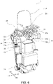
- Fig. 6 is a perspective view illustrating one example of the upper body 30 in the state where the secondary battery unit 100 is removed in Fig. 3 .
- the secondary battery unit 100 is detachably attached to a back part of the upper body 30.
- back parts of the upper body 30 and the lower body 40 correspond to the back and the buttocks of the humanoid robot 1, respectively, and is a part of the upper body 30 in the rearward bending direction.
- Front parts of the upper body 30 and the lower body 40 correspond to the chest and the abdomen of the humanoid robot 1, respectively.
- the rearward bending direction is referred to as a "back direction BD”
- the forward bending direction is referred to as a "front direction FD”
- the right side with respect to the front direction FD is referred to as a “right direction RD”
- the left side with respect to the front direction FD is referred to as a "left direction LD.”
- the secondary battery unit 100 includes secondary battery modules 110-130 and a base 140.
- the secondary battery module 110 is a top secondary battery module disposed at an upper part of the upper body 30.
- the secondary battery module 120 is a back secondary battery module disposed at a back part of the upper body 30.
- the secondary battery module 130 is a side secondary battery module disposed at a side part of the upper body 30.
- the base 140 couples the secondary battery modules 110-130 to each other, and is detachably attached to the upper body 30 together with the secondary battery modules 110-130.
- the top secondary battery module 110 and the side secondary battery module 130 are disposed around the upper body 30 in a direction which intersects with the front-and-rear direction of the upper body 30.
- the top secondary battery module 110 and the side secondary battery module 130 are disposed around the upper body 30 in a direction perpendicular to the front-and-rear direction of the upper body 30.
- Such secondary battery modules 110-130 are disposed so as to surround the upper body 30.
- the back secondary battery module 120 is one example of a "first secondary battery module”
- the top secondary battery module 110 and the side secondary battery module 130 are examples of a "second secondary battery module.”
- Each of the secondary battery modules 110-130 includes one or more secondary batteries 150.
- Each of the secondary battery modules 110-130 may include one or more integrated secondary batteries 150, or may include one or more separated secondary batteries 150.
- the secondary battery 150 is also referred to as a "rechargeable battery” which is electrically chargeable and dischargeable.
- the secondary battery 150 may be comprised of a lead secondary battery, a lithium-ion rechargeable battery, a nickel-hydrogen secondary battery, or a nickel-cadmium secondary battery.
- the top secondary battery module 110 is comprised of a pair of top secondary battery modules 110a and 110b.
- the top secondary battery modules 110a and 110b are disposed on left and right shoulders 32a and 32b of the upper body 30 of the humanoid robot 1, respectively.
- the top secondary battery module 110a when distinguishing the two top secondary battery modules, they are expressed as “the top secondary battery module 110a” and “the top secondary battery module 110b,” and when not distinguishing therebetween, each is expressed as “the top secondary battery module 110.”
- the shoulders 32a and 32b are provided to the upper body 30, and they are the joint parts between the left and right arms 50 and the upper body 30, respectively.
- Each of the shoulders 32a and 32b includes a joint 33 to which the arm 50 is connected, and a drive 34 for the joint 33.
- the drive 34 includes a servomotor 34a and a reduction gear 34b.
- the reduction gear 34b slows down a rotational speed of a rotational driving force of the servomotor 34a while increasing the rotational driving force, and transmits the rotational driving force to the joint 33.
- the rotational driving force of the reduction gear 34b may be transmitted to the joint 33 via a drive belt or a gear mechanism.
- the side secondary battery module 130 is comprised of a pair of side secondary battery modules 130a and 130b.
- the side secondary battery modules 130a and 130b are disposed at the left and right side parts of the upper body 30 of the humanoid robot 1, respectively.
- the side secondary battery modules 130a and 130b are disposed below the shoulders 32a and 32b, respectively.
- the side secondary battery modules 130a and 130b are disposed below the top secondary battery modules 110a and 110b, respectively.
- the terms “up(ward)” and “above” as used herein refer to a direction from the legs 60 to the head 10 of the humanoid robot 1 in the upright position
- the terms “down(ward)” and “below” as used herein refer to a direction from the head 10 to the legs 60 of the humanoid robot 1.
- the side secondary battery module 130a when distinguishing the two side secondary battery modules from each other, they are expressed as “the side secondary battery module 130a” and “the side secondary battery module 130b,” and when not distinguishing therebetween, each are expressed as “the side secondary battery module 130.”
- the single back secondary battery module 120 is disposed at a position between the pair of top secondary battery modules 110a and 110b, and between the pair of side secondary battery modules 130a and 130b.
- the top secondary battery modules 110a and 110b are disposed at equidistance positions in the left direction LD and the right direction RD, centering on the back secondary battery module 120.
- the side secondary battery modules 130a and 130b are disposed at equidistance positions in the left direction LD and the right direction RD, centering on the back secondary battery module 120.
- Fig. 7 is a perspective view illustrating one example of a configuration of the secondary battery module 100 according to this embodiment.
- the base 140 is a frame-like member.
- the base 140 detachably carries the top secondary battery modules 110a and 110b, the back secondary battery module 120, and the side secondary battery modules 130a and 130b.
- Such a base 140 may be made of non-conductive material, such as plastic or resin.
- the base 140 includes a top left accommodating part 141a, top left fixing parts 141aa, a top right accommodating part 141b, top right fixing parts 141ba, a back accommodating part 142, back fixing parts 142a, a side left accommodating part 143a, side left fixing parts 143aa, a side right accommodating part 143b, and side right fixing parts 143ba.
- the back accommodating part 142 is one example of a "first accommodating part,” and the back fixing part 142a is one example of a "first fixing part.”
- the top left accommodating part 141a, the top right accommodating part 141b, the side left accommodating part 143a, and the side right accommodating part 143b are examples of a "second accommodating part.”
- the top left fixing part 141aa, the top right fixing part 141ba, the side left fixing part 143aa, and the side right fixing part 143ba are examples of a "second fixing part.”
- the base 140 includes a first left accommodation connecting part 144a which couples the top left accommodating part 141a to the side left accommodating part 143a, a second left accommodation connecting part 145a which couples the top left accommodating part 141a to the back accommodating part 142, a third left accommodation connecting part 146a which couples the back accommodating part 142 to the side left accommodating part 143a, a first right accommodation connecting part 144b which couples the top right accommodating part 141b to the side right accommodating part 143b, a second right accommodation connecting part 145b which couples the top right accommodating part 141b to the back accommodating part 142, and a third right accommodation connecting part 146b which couples the back accommodating part 142 to the side right accommodating part 143b.
- first left accommodation connecting part 144a, the second left accommodation connecting part 145a, the first right accommodation connecting part 144b, and the second right accommodation connecting part 145b extend in the up-and-down direction
- their extending direction may be directions other than the up-and-down direction
- third left accommodation connecting part 146a and the third right accommodation connecting part 146b extend in the left-and-right direction
- their extending direction may be directions other than the left-and-right direction.
- Each of the accommodating parts 141a, 141b, 142, 143a, and 143b has a rectangular cylindrical shape with a bottom (i.e., has a box shape which opens at one face), which accommodates the secondary battery modules 110a, 110b, 120, 130a, and 130b of a rectangular parallelepiped shape. Further, each of the accommodating parts 141a, 141b, 142, 143a, and 143b opens outwardly from the upper body 30 in the state where the secondary battery unit 100 is attached to the upper body 30. Thus, in the state where the secondary battery unit 100 is attached to the upper body 30, the secondary battery 150 can be accommodated into the accommodating part from outside the upper body 30, and can be removed as well (i.e., a replacement is possible).
- the fixing parts 141aa, 141ba, 142a, 143aa, and 143ba are disposed at the accommodating parts 141a, 141b, 142, 143a, and 143b, respectively.
- the fixing parts 141aa, 141ba, 142a, 143aa, and 143ba fix the secondary battery modules 110a, 110b, 120, 130a, and 130b which are accommodated in the accommodating parts 141a, 141b, 142, 143a, and 143b to the accommodating parts, respectively.
- each of the fixing parts 141aa, 141ba, 142a, 143aa, and 143ba includes a belt-like Hook-and-Loop fastener which detachably fixes the secondary battery modules 110a, 110b, 120, 130a, and 130b to the accommodating parts 141a, 141b, 142, 143a, and 143b, respectively, they may have any configuration as long as the above-described fixation is possible.
- One example of the Hook-and-Loop fastener is Velcro ® .
- the belt-like Hook-and-Loop fastener fixes the secondary battery module to the accommodating part by being wound around the external surface of the secondary battery module.
- the top left accommodating part 141a can accommodate the top secondary battery module 110a including one secondary battery 150.
- the top right accommodating part 141b can accommodate the top secondary battery module 110b including one secondary battery 150.
- the back accommodating part 142 can accommodate the back secondary battery module 120 including two secondary batteries 150.
- the side left accommodating part 143a can accommodate the side secondary battery module 130a including two secondary batteries 150.
- the side right accommodating part 143b can accommodate the side secondary battery module 130b including two secondary batteries 150.
- the two secondary batteries 150 which are accommodated in the side accommodating parts 143a and 143b are lined up in the front-and-rear direction along the cladding 31 of the upper body 30, so as not to project in the left direction LD and the right direction RD, respectively.
- the center of gravity in the state where it is attached to the upper body 30 in such a secondary battery unit 100 is located at a position which is offset downwardly. But, the offset in the back direction BD is suppressed.
- the base 140 includes attaching parts 147a and 147b in the first accommodation connecting parts 144a and 144b.
- the attaching parts 147a and 147b are configured so as to detachably fit onto the shoulders 32a and 32b, respectively.
- the attaching parts 147a and 147b is comprised of a U-shaped member which opens in the front direction FD, they may have any configuration as long as they are detachably fixed to the shoulders 32a and 32b.
- the attaching parts 147a and 147b are examples of a "fitting part.”
- the attaching parts 147a and 147b are configured to be fitted onto to the drives 34 of the shoulders 32a and 32b in the front direction FD from the rear, respectively.
- the attaching parts 147a and 147b fit onto outer circumferential surfaces of the drives 34 of the shoulders 32a and 32b from outside, and they are fixed to the shoulders 32a and 32b, respectively.
- each of the attaching parts 147a and 147b fits onto upper and lower outer circumferential surfaces of the drive 34.
- a recess 147c formed in a lower part of each of the attaching parts 147a and 147b may be configured to engage or fit onto a protrusion 34c (see Fig. 4 ) formed in the lower outer circumferential surface of the drive 34.
- each of the attaching parts 147a and 147b is positioned with respect to the drive 34.
- the recess 147c and the protrusion 34c may be configured to fit or engage by snap fit etc. so that they are not easily escaped from the fitting or engagement state.
- the base 140 is fixed to the upper body 30 in the up-and-down direction, the left-and-right direction, and the front-and-rear direction by fitting the attaching parts 147a and 147b onto the shoulders 32a and 32b, respectively.
- the fitting of the attaching parts 147a and 147b is released by pulling the attaching parts 147a and 147b in the back direction BD, respectively, and thereby, the base 140 is removed from the upper body 30.
- Such a base 140 may be comprised of a single member in which parts continue so as to be integrated, or may be formed by connecting a plurality of members.
- the secondary battery unit 100 constitutes a single module in which all the secondary battery modules 110a, 110b, 120, 130a, and 130b, and the base 140 are integrated. Since the base 140 is attachable to and detachable from the upper body 30, the secondary battery unit 100 makes it possible to attach and detach the secondary battery modules 110a, 110b, 120, 130a, and 130b to/from the upper body 30 all at once. Further, the base 140 is configured to arrange the secondary battery modules 110a, 110b, 120, 130a, and 130b so as not to interfere with the head 10, the neck 20, the shoulders 32a and 32b, and the joint 70, avoiding their operating areas.
- each of the secondary battery modules 110a, 110b, 120, 130a, and 130b is electrically connected with the humanoid robot 1.
- a movable terminal of the upper body 30 is connected to the terminal 160 fixed to the base 140, a terminal 160 movable to the base 140 may be connected to the terminal of the upper body 30.
- a fastener such as the Hook-and-Loop fastener may be disposed at the terminal 160. Further, each terminal 160 may be held by the fixing part 141aa, 141ba, 142a, 143aa, or 143ba, or other constituent members via the fastener. Therefore, it becomes possible to smoothly perform the attachment and detachment of the secondary battery unit 100 to/from the upper body 30, without being influenced by the terminal 160, the cable (not illustrated), etc.
- the upper body 30 includes an electrical equipment box 36 inside a skeleton frame 35 which constitutes the frame of the upper body 30.
- the electrical equipment box 36 includes, therein, the electrical equipment including a circuit board which controls operation of each drive etc. of the humanoid robot 1.
- the back secondary battery module 120 is adjacent to the electrical equipment box 36 via the back accommodating part 142 in the back direction BD from the electrical equipment box 36.
- the side secondary battery module 130a is adjacent to the electrical equipment box 36 via the side left accommodating part 143a in the left direction LD from the electrical equipment box 36.
- the side secondary battery module 130b is adjacent to the electrical equipment box 36 via the side right accommodating part 143b in the right direction RD from the electrical equipment box 36.
- the back secondary battery module 120 and the side secondary battery modules 130a and 130b also function as a protection member of the electrical equipment box 36. Further, by making the base 140 from a resin with low thermal conductivity etc., heat transfer between the electrical equipment box 36 and the back secondary battery module 120 is suppressed, and heat transfer between the electrical equipment box 36 and the side secondary battery modules 130a and 130b is suppressed. Therefore, the electrical equipment inside the electrical equipment box 36 is suppressed from being high in the temperature.
- the shoulders 32a and 32b project from the electrical equipment box 36 in the left direction LD and the right direction RD, respectively.
- the side secondary battery modules 130a and 130b are fitted below the shoulders 32a and 32b so that they do not project from the shoulders 32a and 32b in the left direction LD and the right direction RD, respectively. That is, the side secondary battery modules 130a and 130b are fitted in hollows formed in the left and right flanks of the upper body 30, respectively. Therefore, it is suppressed that the side secondary battery modules 130a and 130b interfere with the left and right arms 50.
- the secondary battery unit 100 includes the back secondary battery module 120 disposed on the back part which is at least either one of the front part or the back part of the upper body 30 of the humanoid robot 1, the top secondary battery module 110 and the side secondary battery module 130 disposed around the upper body 30 in the direction which intersects with the front-and-rear direction of the upper body 30, the base 140 which couples the secondary battery modules 110-130 to each other.
- the base 140 is detachably attached to the upper body 30 along with the secondary battery modules 110-130.
- the secondary battery modules 110-130 are disposed so as to be distributed around the upper body 30. Therefore, in the humanoid robot 1 carrying the secondary battery unit 100, it may be suppressed that the center-of-gravity position of the humanoid robot 1 is deviated and offset from the center axis of the humanoid robot 1 (i.e., the balance of the center of gravity is offset).
- the center axis of the humanoid robot 1 may be the axis which passes through the head 10 and the neck 20 and extends in the up-and-down direction, or may be the center axis when the humanoid robot 1 turns left and right.
- the secondary battery modules 110-130 are collectively attached and detached to/from the upper body 30, together with the base 140. Therefore, the attachment and detachment of the secondary battery modules 110-130 become easier.
- the secondary battery modules 110-130 may be disposed so as to surround the upper body 30. According to this configuration, the secondary battery modules 110-130 can be disposed so as to be distributed around the upper body 30.
- the secondary battery modules 110 and 130 may be disposed at the upper part and the side part of the upper body 30. According to this configuration, the secondary battery modules 110-130 can be disposed so as to be distributed to the upper part, the back part, and the side part of the upper body 30.
- the base 140 may include the attaching parts 147a and 147b as the fitting parts which detachably fit onto the upper body 30 of the humanoid robot 1.
- the attaching parts 147a and 147b may be configured so as to fit onto the shoulders 32a and 32b of the upper body 30, respectively.
- the attaching parts 147a and 147b may be disposed at the first accommodation connecting parts 144a and 144b of the base 140 which couple the top secondary battery modules 110a and 110b and the side secondary battery modules 130a and 130b, respectively. According to this configuration, the attachment and detachment of the base 140 to/from the upper body 30 become easier.
- the top secondary battery modules 110a and 110b may be disposed so as to be placed on the shoulders 32a and 32b of the upper body 30.
- the shoulders 32a and 32b may be joint parts between the left and right arms 50 and the upper body 30 of the humanoid robot 1. According to this configuration, the layout of top secondary battery modules 110a and 110b to the upper body 30 becomes easier.
- the top secondary battery modules 110a and 110b are stably supported by the shoulders 32a and 32b from below.
- the base 140 may include the top accommodating parts 141a and 141b which accommodate the top secondary battery modules 110a and 110b, and the top fixing parts 141aa and 141ba which fix the top secondary battery modules 110a and 110b to the top accommodating parts 141a and 141b. Further, the base 140 may include the back accommodating part 142 which accommodates the back secondary battery module 120, and the back fixing part 142a which fixes the back secondary battery module 120 to the back accommodating part 142. The base 140 may include the side accommodating parts 143a and 143b which accommodate the side secondary battery modules 130a and 130b, and the side fixing parts 143aa and 143ba which fix the side secondary battery modules 130a and 130b to the side accommodating parts 143a and 143b. According to this configuration, it becomes easy to attach the top secondary battery modules 110a and 110b, the back secondary battery module 120, and the side secondary battery modules 130a and 130b to the given positions of the base 140.
- the top accommodating parts 141a and 141b may be disposed so that they open outwardly from the upper body 30 so that accommodation and removal of the top secondary battery modules 110a and 110b from outside the upper body 30 are possible, respectively.
- the back accommodating part 142 may be disposed so that they open outwardly from the upper body 30 so that accommodation and removal of the back secondary battery module 120 from outside the upper body 30 are possible.
- the side accommodating parts 143a and 143b may be disposed so that they open outwardly from the upper body 30 so that accommodation and removal of the side secondary battery modules 130a and 130b from outside the upper body 30 are possible, respectively. According to this configuration, the replacement of the secondary battery module in the state where the secondary battery unit 100 is attached to the upper body 30 is possible, and therefore, the replacement of the secondary battery module becomes easier.
- the base 140 may include the first accommodation connecting parts 144a and 144b which couple the top accommodating parts 141a and 141b to the side accommodating parts 143a and 143b, respectively, the second accommodation connecting parts 145a and 145b which couple the top accommodating parts 141a and 141b to the back accommodating part 142, respectively, and the third accommodation connecting parts 146a and 146b which couple the back accommodating part 142 to the side accommodating parts 143a and 143b, respectively.
- the accommodating parts 141a, 141b, 142, 143a, and 143b are connected mutually, it becomes possible to hold the position of each accommodating part on the base 140 (i.e., a relative position of each accommodating part).
- the fixing parts 141aa, 141ba, 142a, 143aa, and 143ba may include a Hook-and-Loop fastener which detachably fixes the secondary battery modules 110a, 110b, 120, 130a, and 130b to the accommodating parts 141a, 141b, 142, 143a, and 143b, respectively. According to this configuration, operation for fixing and releasing the secondary battery modules 110a, 110b, 120, 130a, and 130b becomes simpler.
- the secondary battery unit 100 may be provided with a pair of top secondary battery modules 110a and 110b, and a pair of side secondary battery modules 130a and 130b.
- the top secondary battery modules 110a and 110b may be disposed so as to be placed on the left and right shoulders 32a and 32b of the humanoid robot 1, respectively.
- the side secondary battery modules 130a and 130b may be disposed at the left and right side parts of the upper body 30, below the joint parts between the left and right arms 50 and the upper body 30 of the humanoid robot 1, respectively.
- the back secondary battery module 120 may be disposed at the position between the pair of top secondary battery modules 110a and 110b, and between the pair of side secondary battery modules 130a and 130b.
- the humanoid robot 1 according to this embodiment is provided with the secondary battery unit 100 and the upper body 30. According to this configuration, similar effects to the secondary battery unit 100 according to the above embodiment can be acquired.
- the secondary battery unit 100 is provided with the top secondary battery modules 110a and 110b, the back secondary battery module 120, and the side secondary battery modules 130a and 130b, it is not limited to this configuration.
- the secondary battery unit 100 may not be provided with the top secondary battery modules 110a and 110b, the back secondary battery module 120, or the side secondary battery modules 130a and 130b.
- the secondary battery unit 100 may be provided with the back secondary battery module 120 disposed at the back part of the upper body 30, and the side secondary battery modules 130a and 130b disposed at the side parts of the upper body 30. According to the above configuration, it becomes possible to lower the center-of-gravity position of the humanoid robot 1 to which the secondary battery unit 100 is attached.
- the secondary battery unit 100 may be provided with the top secondary battery modules 110a and 110b and the back secondary battery module 120.
- the secondary battery unit 100 may be provided with a front secondary battery module disposed at the front part of the upper body 30, instead of the back secondary battery module 120.
- the secondary battery unit 100 may be provided with the front secondary battery module, the top secondary battery modules 110a and 110b, and the side secondary battery modules 130a and 130b, or may be provided with the front secondary battery module, and the side secondary battery modules 130a and 130b, or may be provided with the front secondary battery module, and the top secondary battery modules 110a and 110b.
- the secondary battery unit 100 may be provided with further secondary battery module(s).
- the further secondary battery modules may be disposed at the front part of the upper body 30 and the lower body 40.
- the top secondary battery modules 110a and 110b are disposed so as to be separated from each other, they may be integrated.
- the top secondary battery module 110 may include three or more separately-disposed secondary battery modules.
- the side secondary battery modules 130a and 130b are disposed so as to be separated from each other, they may be integrated.
- the side secondary battery module 130 may include three or more separately-disposed secondary battery modules.
- the back secondary battery module 120 may include two or more separately-disposed secondary battery modules.
- the base 140 is attached to the upper body 30 by fitting onto the shoulders 32a and 32b, it is not limited to this configuration.
- the base 140 may be configured to fit onto the upper body 30 or the neck 20.
- the base 140 may be configured to be attached to the upper body 30 by a fastening member such as screws.
- the secondary battery unit 100 is disposed at the back part of the upper body 30, it is not limited to this configuration.
- the secondary battery unit 100 may be disposed at the front part of the upper body 30, or may be disposed over the front part and the back part of the upper body 30.
- the secondary battery unit 100 may be disposed at the back part, the front part, or both the front part and the back part of the lower body 40.
- the secondary battery unit 100 may be disposed over the upper body 30 and the lower body 40.
- at least one of the secondary battery modules may be disposed at the front part, the back part, the left and right side parts of the lower body 40, or the crotch part between the legs 60.
Landscapes
- Chemical & Material Sciences (AREA)
- Chemical Kinetics & Catalysis (AREA)
- Electrochemistry (AREA)
- General Chemical & Material Sciences (AREA)
- Engineering & Computer Science (AREA)
- Robotics (AREA)
- Mechanical Engineering (AREA)
- Manipulator (AREA)
- Battery Mounting, Suspending (AREA)
Applications Claiming Priority (2)
| Application Number | Priority Date | Filing Date | Title |
|---|---|---|---|
| JP2019159762A JP7353104B2 (ja) | 2019-09-02 | 2019-09-02 | 蓄電池ユニット及び人型ロボット |
| PCT/JP2020/033231 WO2021045086A1 (ja) | 2019-09-02 | 2020-09-02 | 蓄電池ユニット及び人型ロボット |
Publications (3)
| Publication Number | Publication Date |
|---|---|
| EP4026657A1 true EP4026657A1 (de) | 2022-07-13 |
| EP4026657A4 EP4026657A4 (de) | 2023-10-11 |
| EP4026657B1 EP4026657B1 (de) | 2025-01-15 |
Family
ID=74847972
Family Applications (1)
| Application Number | Title | Priority Date | Filing Date |
|---|---|---|---|
| EP20860309.2A Active EP4026657B1 (de) | 2019-09-02 | 2020-09-02 | Akkumulatorbatterieeinheit und humanoider roboter |
Country Status (6)
| Country | Link |
|---|---|
| US (1) | US12283704B2 (de) |
| EP (1) | EP4026657B1 (de) |
| JP (1) | JP7353104B2 (de) |
| CN (1) | CN114391197A (de) |
| ES (1) | ES3007458T3 (de) |
| WO (1) | WO2021045086A1 (de) |
Families Citing this family (12)
| Publication number | Priority date | Publication date | Assignee | Title |
|---|---|---|---|---|
| JP7353104B2 (ja) * | 2019-09-02 | 2023-09-29 | 川崎重工業株式会社 | 蓄電池ユニット及び人型ロボット |
| JP2025534325A (ja) * | 2022-09-30 | 2025-10-15 | テスラ,インコーポレイテッド | ロボット用垂直エネルギー貯蔵装置用筐体及びそのシステム |
| JP2025535012A (ja) * | 2022-09-30 | 2025-10-22 | テスラ,インコーポレイテッド | アクチュエータおよびアクチュエータ設計方法論 |
| USD1118726S1 (en) | 2023-04-17 | 2026-03-17 | Figure Ai Inc. | Humanoid robot |
| US12365094B2 (en) | 2023-04-17 | 2025-07-22 | Figure Ai Inc. | Head and neck assembly for a humanoid robot |
| US12539618B1 (en) | 2023-04-17 | 2026-02-03 | Figure Ai Inc. | Head and neck assembly of a humanoid robot |
| WO2025175321A1 (en) * | 2024-02-15 | 2025-08-21 | Figure Ai Inc. | Torso of a humanoid robot |
| US12605824B2 (en) | 2024-02-26 | 2026-04-21 | Figure Ai Inc. | Humanoid robot |
| US12578733B2 (en) | 2024-09-04 | 2026-03-17 | Figure Ai Inc. | Bipedal action model for humanoid robot |
| US12611767B2 (en) | 2024-09-06 | 2026-04-28 | Figure Ai Inc. | System and method for efficient control of a humanoid robot |
| US12611766B2 (en) | 2024-09-13 | 2026-04-28 | Figure Ai Inc. | Humanoid robot with advanced kinematics |
| CN119427396B (zh) * | 2025-01-13 | 2025-05-27 | 上海傅利叶智能科技有限公司 | 躯干装置和人形机器人 |
Family Cites Families (14)
| Publication number | Priority date | Publication date | Assignee | Title |
|---|---|---|---|---|
| JP3655056B2 (ja) * | 1997-08-04 | 2005-06-02 | 本田技研工業株式会社 | 脚式移動ロボットの制御装置 |
| JP4540156B2 (ja) * | 1999-11-02 | 2010-09-08 | ソニー株式会社 | ロボットの重心位置制御方法 |
| JP2001239479A (ja) | 1999-12-24 | 2001-09-04 | Sony Corp | 脚式移動ロボット及びロボットのための外装モジュール |
| KR100485038B1 (ko) * | 2000-09-29 | 2005-04-22 | 혼다 기켄 고교 가부시키가이샤 | 2족보행 로봇 |
| JP4478313B2 (ja) * | 2000-10-12 | 2010-06-09 | 本田技研工業株式会社 | 蓄電池を搭載した二足歩行ロボット |
| JP4478314B2 (ja) | 2000-10-12 | 2010-06-09 | 本田技研工業株式会社 | 蓄電池を搭載した二足歩行ロボット |
| JP2002120188A (ja) | 2000-10-12 | 2002-04-23 | Honda Motor Co Ltd | 蓄電池を搭載した二足歩行ロボット |
| WO2002030631A2 (en) | 2000-10-12 | 2002-04-18 | Honda Giken Kogyo Kabushiki Kaisha | Bipedal robot with storage battery |
| JP4252721B2 (ja) * | 2000-11-17 | 2009-04-08 | 本田技研工業株式会社 | 二足歩行ロボット |
| JP2008296368A (ja) * | 2008-09-01 | 2008-12-11 | Sony Corp | 脚式移動ロボット |
| CN107284547A (zh) * | 2016-03-31 | 2017-10-24 | 深圳光启合众科技有限公司 | 一种机器人电池重心调整结构 |
| DE102019006945A1 (de) * | 2018-10-11 | 2020-04-16 | Makita Corporation | Akkumulatorenmontagevorrichtung |
| JP7353104B2 (ja) * | 2019-09-02 | 2023-09-29 | 川崎重工業株式会社 | 蓄電池ユニット及び人型ロボット |
| JP7274385B2 (ja) * | 2019-09-02 | 2023-05-16 | 川崎重工業株式会社 | 蓄電池収容構造及び人型ロボット |
-
2019
- 2019-09-02 JP JP2019159762A patent/JP7353104B2/ja active Active
-
2020
- 2020-09-02 US US17/638,209 patent/US12283704B2/en active Active
- 2020-09-02 WO PCT/JP2020/033231 patent/WO2021045086A1/ja not_active Ceased
- 2020-09-02 EP EP20860309.2A patent/EP4026657B1/de active Active
- 2020-09-02 CN CN202080061993.7A patent/CN114391197A/zh active Pending
- 2020-09-02 ES ES20860309T patent/ES3007458T3/es active Active
Also Published As
| Publication number | Publication date |
|---|---|
| CN114391197A (zh) | 2022-04-22 |
| ES3007458T3 (en) | 2025-03-20 |
| JP7353104B2 (ja) | 2023-09-29 |
| JP2021037571A (ja) | 2021-03-11 |
| EP4026657B1 (de) | 2025-01-15 |
| US20220294062A1 (en) | 2022-09-15 |
| EP4026657A4 (de) | 2023-10-11 |
| US12283704B2 (en) | 2025-04-22 |
| WO2021045086A1 (ja) | 2021-03-11 |
Similar Documents
| Publication | Publication Date | Title |
|---|---|---|
| EP4026657B1 (de) | Akkumulatorbatterieeinheit und humanoider roboter | |
| US6640160B2 (en) | Biped ambulatory robot | |
| US5929597A (en) | Portable electrical power system to supply direct current voltage | |
| CN104411463B (zh) | 背包型电源 | |
| CN104411464B (zh) | 背包型电源 | |
| US20150280467A1 (en) | Electric Vehicle, and Battery Pack | |
| US20050082920A1 (en) | Electrical connection arrangement for hand-held tools with auxiliary devices | |
| DE60003499D1 (de) | Lösbare Verbindung zwischen Batteriemodulen und elektrischen Geräten | |
| JP2013521136A (ja) | バッテリー駆動電動工具 | |
| KR100485038B1 (ko) | 2족보행 로봇 | |
| JP5778538B2 (ja) | 電動作業機 | |
| JP2000164182A (ja) | バッテリーパック | |
| JP6887319B2 (ja) | 電力供給システム、電動工具システム、及び電動工具 | |
| CN114340854B (zh) | 蓄电池容纳结构和人型机器人 | |
| EP2594369A2 (de) | Elektrisches Werkzeug | |
| CN116901043B (zh) | 一种外骨骼机器人膝关节直驱助力装置 | |
| US20250192599A1 (en) | Integrated, shareable power supply for medical procedure devices and methods of making and using same | |
| US20260126663A1 (en) | Head-mounted display device | |
| JP7665794B2 (ja) | 電力装置 | |
| JP7604143B2 (ja) | 手持式作業機 | |
| CN121315908A (zh) | 一种电力巡检外骨骼模块化结构 | |
| CN111386181A (zh) | 机器人的股关节构造体 | |
| KR20120004928U (ko) | 충전식 전동공구 |
Legal Events
| Date | Code | Title | Description |
|---|---|---|---|
| STAA | Information on the status of an ep patent application or granted ep patent |
Free format text: STATUS: THE INTERNATIONAL PUBLICATION HAS BEEN MADE |
|
| PUAI | Public reference made under article 153(3) epc to a published international application that has entered the european phase |
Free format text: ORIGINAL CODE: 0009012 |
|
| STAA | Information on the status of an ep patent application or granted ep patent |
Free format text: STATUS: REQUEST FOR EXAMINATION WAS MADE |
|
| 17P | Request for examination filed |
Effective date: 20220210 |
|
| AK | Designated contracting states |
Kind code of ref document: A1 Designated state(s): AL AT BE BG CH CY CZ DE DK EE ES FI FR GB GR HR HU IE IS IT LI LT LU LV MC MK MT NL NO PL PT RO RS SE SI SK SM TR |
|
| DAV | Request for validation of the european patent (deleted) | ||
| DAX | Request for extension of the european patent (deleted) | ||
| A4 | Supplementary search report drawn up and despatched |
Effective date: 20230912 |
|
| RIC1 | Information provided on ipc code assigned before grant |
Ipc: H01M 50/20 20210101ALI20230906BHEP Ipc: B25J 19/00 20060101ALI20230906BHEP Ipc: B25J 9/06 20060101ALI20230906BHEP Ipc: B25J 5/00 20060101AFI20230906BHEP |
|
| GRAP | Despatch of communication of intention to grant a patent |
Free format text: ORIGINAL CODE: EPIDOSNIGR1 |
|
| STAA | Information on the status of an ep patent application or granted ep patent |
Free format text: STATUS: GRANT OF PATENT IS INTENDED |
|
| INTG | Intention to grant announced |
Effective date: 20240917 |
|
| GRAS | Grant fee paid |
Free format text: ORIGINAL CODE: EPIDOSNIGR3 |
|
| GRAA | (expected) grant |
Free format text: ORIGINAL CODE: 0009210 |
|
| STAA | Information on the status of an ep patent application or granted ep patent |
Free format text: STATUS: THE PATENT HAS BEEN GRANTED |
|
| AK | Designated contracting states |
Kind code of ref document: B1 Designated state(s): AL AT BE BG CH CY CZ DE DK EE ES FI FR GB GR HR HU IE IS IT LI LT LU LV MC MK MT NL NO PL PT RO RS SE SI SK SM TR |
|
| REG | Reference to a national code |
Ref country code: CH Ref legal event code: EP Ref country code: GB Ref legal event code: FG4D |
|
| REG | Reference to a national code |
Ref country code: DE Ref legal event code: R096 Ref document number: 602020044962 Country of ref document: DE |
|
| REG | Reference to a national code |
Ref country code: IE Ref legal event code: FG4D |
|
| REG | Reference to a national code |
Ref country code: ES Ref legal event code: FG2A Ref document number: 3007458 Country of ref document: ES Kind code of ref document: T3 Effective date: 20250320 |
|
| REG | Reference to a national code |
Ref country code: NL Ref legal event code: MP Effective date: 20250115 |
|
| PG25 | Lapsed in a contracting state [announced via postgrant information from national office to epo] |
Ref country code: NL Free format text: LAPSE BECAUSE OF FAILURE TO SUBMIT A TRANSLATION OF THE DESCRIPTION OR TO PAY THE FEE WITHIN THE PRESCRIBED TIME-LIMIT Effective date: 20250115 |
|
| PG25 | Lapsed in a contracting state [announced via postgrant information from national office to epo] |
Ref country code: RS Free format text: LAPSE BECAUSE OF FAILURE TO SUBMIT A TRANSLATION OF THE DESCRIPTION OR TO PAY THE FEE WITHIN THE PRESCRIBED TIME-LIMIT Effective date: 20250415 |
|
| PG25 | Lapsed in a contracting state [announced via postgrant information from national office to epo] |
Ref country code: FI Free format text: LAPSE BECAUSE OF FAILURE TO SUBMIT A TRANSLATION OF THE DESCRIPTION OR TO PAY THE FEE WITHIN THE PRESCRIBED TIME-LIMIT Effective date: 20250115 |
|
| PG25 | Lapsed in a contracting state [announced via postgrant information from national office to epo] |
Ref country code: PL Free format text: LAPSE BECAUSE OF FAILURE TO SUBMIT A TRANSLATION OF THE DESCRIPTION OR TO PAY THE FEE WITHIN THE PRESCRIBED TIME-LIMIT Effective date: 20250115 |
|
| REG | Reference to a national code |
Ref country code: LT Ref legal event code: MG9D |
|
| PG25 | Lapsed in a contracting state [announced via postgrant information from national office to epo] |
Ref country code: IS Free format text: LAPSE BECAUSE OF FAILURE TO SUBMIT A TRANSLATION OF THE DESCRIPTION OR TO PAY THE FEE WITHIN THE PRESCRIBED TIME-LIMIT Effective date: 20250515 Ref country code: NO Free format text: LAPSE BECAUSE OF FAILURE TO SUBMIT A TRANSLATION OF THE DESCRIPTION OR TO PAY THE FEE WITHIN THE PRESCRIBED TIME-LIMIT Effective date: 20250415 |
|
| REG | Reference to a national code |
Ref country code: AT Ref legal event code: MK05 Ref document number: 1759546 Country of ref document: AT Kind code of ref document: T Effective date: 20250115 |
|
| PG25 | Lapsed in a contracting state [announced via postgrant information from national office to epo] |
Ref country code: HR Free format text: LAPSE BECAUSE OF FAILURE TO SUBMIT A TRANSLATION OF THE DESCRIPTION OR TO PAY THE FEE WITHIN THE PRESCRIBED TIME-LIMIT Effective date: 20250115 |
|
| PG25 | Lapsed in a contracting state [announced via postgrant information from national office to epo] |
Ref country code: LV Free format text: LAPSE BECAUSE OF FAILURE TO SUBMIT A TRANSLATION OF THE DESCRIPTION OR TO PAY THE FEE WITHIN THE PRESCRIBED TIME-LIMIT Effective date: 20250115 Ref country code: PT Free format text: LAPSE BECAUSE OF FAILURE TO SUBMIT A TRANSLATION OF THE DESCRIPTION OR TO PAY THE FEE WITHIN THE PRESCRIBED TIME-LIMIT Effective date: 20250515 |
|
| PG25 | Lapsed in a contracting state [announced via postgrant information from national office to epo] |
Ref country code: BG Free format text: LAPSE BECAUSE OF FAILURE TO SUBMIT A TRANSLATION OF THE DESCRIPTION OR TO PAY THE FEE WITHIN THE PRESCRIBED TIME-LIMIT Effective date: 20250115 Ref country code: GR Free format text: LAPSE BECAUSE OF FAILURE TO SUBMIT A TRANSLATION OF THE DESCRIPTION OR TO PAY THE FEE WITHIN THE PRESCRIBED TIME-LIMIT Effective date: 20250416 |
|
| PG25 | Lapsed in a contracting state [announced via postgrant information from national office to epo] |
Ref country code: AT Free format text: LAPSE BECAUSE OF FAILURE TO SUBMIT A TRANSLATION OF THE DESCRIPTION OR TO PAY THE FEE WITHIN THE PRESCRIBED TIME-LIMIT Effective date: 20250115 |
|
| PG25 | Lapsed in a contracting state [announced via postgrant information from national office to epo] |
Ref country code: SE Free format text: LAPSE BECAUSE OF FAILURE TO SUBMIT A TRANSLATION OF THE DESCRIPTION OR TO PAY THE FEE WITHIN THE PRESCRIBED TIME-LIMIT Effective date: 20250115 |
|
| PG25 | Lapsed in a contracting state [announced via postgrant information from national office to epo] |
Ref country code: SM Free format text: LAPSE BECAUSE OF FAILURE TO SUBMIT A TRANSLATION OF THE DESCRIPTION OR TO PAY THE FEE WITHIN THE PRESCRIBED TIME-LIMIT Effective date: 20250115 |
|
| PG25 | Lapsed in a contracting state [announced via postgrant information from national office to epo] |
Ref country code: DK Free format text: LAPSE BECAUSE OF FAILURE TO SUBMIT A TRANSLATION OF THE DESCRIPTION OR TO PAY THE FEE WITHIN THE PRESCRIBED TIME-LIMIT Effective date: 20250115 |
|
| PGFP | Annual fee paid to national office [announced via postgrant information from national office to epo] |
Ref country code: DE Payment date: 20250915 Year of fee payment: 6 |
|
| REG | Reference to a national code |
Ref country code: DE Ref legal event code: R097 Ref document number: 602020044962 Country of ref document: DE |
|
| PGFP | Annual fee paid to national office [announced via postgrant information from national office to epo] |
Ref country code: FR Payment date: 20250924 Year of fee payment: 6 |
|
| PG25 | Lapsed in a contracting state [announced via postgrant information from national office to epo] |
Ref country code: CZ Free format text: LAPSE BECAUSE OF FAILURE TO SUBMIT A TRANSLATION OF THE DESCRIPTION OR TO PAY THE FEE WITHIN THE PRESCRIBED TIME-LIMIT Effective date: 20250115 Ref country code: EE Free format text: LAPSE BECAUSE OF FAILURE TO SUBMIT A TRANSLATION OF THE DESCRIPTION OR TO PAY THE FEE WITHIN THE PRESCRIBED TIME-LIMIT Effective date: 20250115 |
|
| PG25 | Lapsed in a contracting state [announced via postgrant information from national office to epo] |
Ref country code: RO Free format text: LAPSE BECAUSE OF FAILURE TO SUBMIT A TRANSLATION OF THE DESCRIPTION OR TO PAY THE FEE WITHIN THE PRESCRIBED TIME-LIMIT Effective date: 20250115 |
|
| PG25 | Lapsed in a contracting state [announced via postgrant information from national office to epo] |
Ref country code: SK Free format text: LAPSE BECAUSE OF FAILURE TO SUBMIT A TRANSLATION OF THE DESCRIPTION OR TO PAY THE FEE WITHIN THE PRESCRIBED TIME-LIMIT Effective date: 20250115 |
|
| PLBE | No opposition filed within time limit |
Free format text: ORIGINAL CODE: 0009261 |
|
| STAA | Information on the status of an ep patent application or granted ep patent |
Free format text: STATUS: NO OPPOSITION FILED WITHIN TIME LIMIT |
|
| REG | Reference to a national code |
Ref country code: CH Ref legal event code: L10 Free format text: ST27 STATUS EVENT CODE: U-0-0-L10-L00 (AS PROVIDED BY THE NATIONAL OFFICE) Effective date: 20251126 |
|
| 26N | No opposition filed |
Effective date: 20251016 |
|
| PGFP | Annual fee paid to national office [announced via postgrant information from national office to epo] |
Ref country code: IT Payment date: 20250930 Year of fee payment: 6 |
|
| PGFP | Annual fee paid to national office [announced via postgrant information from national office to epo] |
Ref country code: ES Payment date: 20251020 Year of fee payment: 6 |
|
| REG | Reference to a national code |
Ref country code: CH Ref legal event code: H13 Free format text: ST27 STATUS EVENT CODE: U-0-0-H10-H13 (AS PROVIDED BY THE NATIONAL OFFICE) Effective date: 20260425 |