EP4026689A1 - Unité d'entraînement hydraulique pour une presse - Google Patents
Unité d'entraînement hydraulique pour une presse Download PDFInfo
- Publication number
- EP4026689A1 EP4026689A1 EP21217269.6A EP21217269A EP4026689A1 EP 4026689 A1 EP4026689 A1 EP 4026689A1 EP 21217269 A EP21217269 A EP 21217269A EP 4026689 A1 EP4026689 A1 EP 4026689A1
- Authority
- EP
- European Patent Office
- Prior art keywords
- chamber
- pressure
- valve
- drive unit
- press
- Prior art date
- Legal status (The legal status is an assumption and is not a legal conclusion. Google has not performed a legal analysis and makes no representation as to the accuracy of the status listed.)
- Withdrawn
Links
- 230000006835 compression Effects 0.000 claims abstract description 23
- 238000007906 compression Methods 0.000 claims abstract description 23
- 238000010586 diagram Methods 0.000 description 4
- 244000208734 Pisonia aculeata Species 0.000 description 3
- 230000006837 decompression Effects 0.000 description 3
- 238000006073 displacement reaction Methods 0.000 description 2
- 230000036316 preload Effects 0.000 description 2
- 230000001419 dependent effect Effects 0.000 description 1
- 238000011982 device technology Methods 0.000 description 1
- 230000005484 gravity Effects 0.000 description 1
- 238000010438 heat treatment Methods 0.000 description 1
- 238000000034 method Methods 0.000 description 1
- 230000001360 synchronised effect Effects 0.000 description 1
- 230000007704 transition Effects 0.000 description 1
Images

Classifications
-
- B—PERFORMING OPERATIONS; TRANSPORTING
- B30—PRESSES
- B30B—PRESSES IN GENERAL
- B30B15/00—Details of, or accessories for, presses; Auxiliary measures in connection with pressing
- B30B15/16—Control arrangements for fluid-driven presses
- B30B15/163—Control arrangements for fluid-driven presses for accumulator-driven presses
-
- B—PERFORMING OPERATIONS; TRANSPORTING
- B30—PRESSES
- B30B—PRESSES IN GENERAL
- B30B15/00—Details of, or accessories for, presses; Auxiliary measures in connection with pressing
- B30B15/16—Control arrangements for fluid-driven presses
-
- F—MECHANICAL ENGINEERING; LIGHTING; HEATING; WEAPONS; BLASTING
- F15—FLUID-PRESSURE ACTUATORS; HYDRAULICS OR PNEUMATICS IN GENERAL
- F15B—SYSTEMS ACTING BY MEANS OF FLUIDS IN GENERAL; FLUID-PRESSURE ACTUATORS, e.g. SERVOMOTORS; DETAILS OF FLUID-PRESSURE SYSTEMS, NOT OTHERWISE PROVIDED FOR
- F15B11/00—Servomotor systems without provision for follow-up action; Circuits therefor
- F15B11/02—Systems essentially incorporating special features for controlling the speed or actuating force of an output member
- F15B11/022—Systems essentially incorporating special features for controlling the speed or actuating force of an output member in which a rapid approach stroke is followed by a slower, high-force working stroke
-
- F—MECHANICAL ENGINEERING; LIGHTING; HEATING; WEAPONS; BLASTING
- F15—FLUID-PRESSURE ACTUATORS; HYDRAULICS OR PNEUMATICS IN GENERAL
- F15B—SYSTEMS ACTING BY MEANS OF FLUIDS IN GENERAL; FLUID-PRESSURE ACTUATORS, e.g. SERVOMOTORS; DETAILS OF FLUID-PRESSURE SYSTEMS, NOT OTHERWISE PROVIDED FOR
- F15B11/00—Servomotor systems without provision for follow-up action; Circuits therefor
- F15B11/02—Systems essentially incorporating special features for controlling the speed or actuating force of an output member
- F15B11/028—Systems essentially incorporating special features for controlling the speed or actuating force of an output member for controlling the actuating force
- F15B11/036—Systems essentially incorporating special features for controlling the speed or actuating force of an output member for controlling the actuating force by means of servomotors having a plurality of working chambers
-
- F—MECHANICAL ENGINEERING; LIGHTING; HEATING; WEAPONS; BLASTING
- F15—FLUID-PRESSURE ACTUATORS; HYDRAULICS OR PNEUMATICS IN GENERAL
- F15B—SYSTEMS ACTING BY MEANS OF FLUIDS IN GENERAL; FLUID-PRESSURE ACTUATORS, e.g. SERVOMOTORS; DETAILS OF FLUID-PRESSURE SYSTEMS, NOT OTHERWISE PROVIDED FOR
- F15B7/00—Systems in which the movement produced is definitely related to the output of a volumetric pump; Telemotors
- F15B7/005—With rotary or crank input
- F15B7/006—Rotary pump input
-
- F—MECHANICAL ENGINEERING; LIGHTING; HEATING; WEAPONS; BLASTING
- F15—FLUID-PRESSURE ACTUATORS; HYDRAULICS OR PNEUMATICS IN GENERAL
- F15B—SYSTEMS ACTING BY MEANS OF FLUIDS IN GENERAL; FLUID-PRESSURE ACTUATORS, e.g. SERVOMOTORS; DETAILS OF FLUID-PRESSURE SYSTEMS, NOT OTHERWISE PROVIDED FOR
- F15B1/00—Installations or systems with accumulators; Supply reservoir or sump assemblies
- F15B1/02—Installations or systems with accumulators
- F15B1/04—Accumulators
- F15B1/08—Accumulators using a gas cushion; Gas charging devices; Indicators or floats therefor
-
- F—MECHANICAL ENGINEERING; LIGHTING; HEATING; WEAPONS; BLASTING
- F15—FLUID-PRESSURE ACTUATORS; HYDRAULICS OR PNEUMATICS IN GENERAL
- F15B—SYSTEMS ACTING BY MEANS OF FLUIDS IN GENERAL; FLUID-PRESSURE ACTUATORS, e.g. SERVOMOTORS; DETAILS OF FLUID-PRESSURE SYSTEMS, NOT OTHERWISE PROVIDED FOR
- F15B15/00—Fluid-actuated devices for displacing a member from one position to another; Gearing associated therewith
- F15B15/08—Characterised by the construction of the motor unit
- F15B15/14—Characterised by the construction of the motor unit of the straight-cylinder type
- F15B15/1423—Component parts; Constructional details
- F15B15/1466—Hollow piston sliding over a stationary rod inside the cylinder
-
- F—MECHANICAL ENGINEERING; LIGHTING; HEATING; WEAPONS; BLASTING
- F15—FLUID-PRESSURE ACTUATORS; HYDRAULICS OR PNEUMATICS IN GENERAL
- F15B—SYSTEMS ACTING BY MEANS OF FLUIDS IN GENERAL; FLUID-PRESSURE ACTUATORS, e.g. SERVOMOTORS; DETAILS OF FLUID-PRESSURE SYSTEMS, NOT OTHERWISE PROVIDED FOR
- F15B15/00—Fluid-actuated devices for displacing a member from one position to another; Gearing associated therewith
- F15B15/18—Combined units comprising both motor and pump
-
- F—MECHANICAL ENGINEERING; LIGHTING; HEATING; WEAPONS; BLASTING
- F15—FLUID-PRESSURE ACTUATORS; HYDRAULICS OR PNEUMATICS IN GENERAL
- F15B—SYSTEMS ACTING BY MEANS OF FLUIDS IN GENERAL; FLUID-PRESSURE ACTUATORS, e.g. SERVOMOTORS; DETAILS OF FLUID-PRESSURE SYSTEMS, NOT OTHERWISE PROVIDED FOR
- F15B15/00—Fluid-actuated devices for displacing a member from one position to another; Gearing associated therewith
- F15B15/20—Other details, e.g. assembly with regulating devices
- F15B15/202—Externally-operated valves mounted in or on the actuator
-
- F—MECHANICAL ENGINEERING; LIGHTING; HEATING; WEAPONS; BLASTING
- F15—FLUID-PRESSURE ACTUATORS; HYDRAULICS OR PNEUMATICS IN GENERAL
- F15B—SYSTEMS ACTING BY MEANS OF FLUIDS IN GENERAL; FLUID-PRESSURE ACTUATORS, e.g. SERVOMOTORS; DETAILS OF FLUID-PRESSURE SYSTEMS, NOT OTHERWISE PROVIDED FOR
- F15B21/00—Common features of fluid actuator systems; Fluid-pressure actuator systems or details thereof, not covered by any other group of this subclass
- F15B21/04—Special measures taken in connection with the properties of the fluid
- F15B21/042—Controlling the temperature of the fluid
- F15B21/0423—Cooling
-
- F—MECHANICAL ENGINEERING; LIGHTING; HEATING; WEAPONS; BLASTING
- F15—FLUID-PRESSURE ACTUATORS; HYDRAULICS OR PNEUMATICS IN GENERAL
- F15B—SYSTEMS ACTING BY MEANS OF FLUIDS IN GENERAL; FLUID-PRESSURE ACTUATORS, e.g. SERVOMOTORS; DETAILS OF FLUID-PRESSURE SYSTEMS, NOT OTHERWISE PROVIDED FOR
- F15B2201/00—Accumulators
- F15B2201/20—Accumulator cushioning means
- F15B2201/205—Accumulator cushioning means using gas
-
- F—MECHANICAL ENGINEERING; LIGHTING; HEATING; WEAPONS; BLASTING
- F15—FLUID-PRESSURE ACTUATORS; HYDRAULICS OR PNEUMATICS IN GENERAL
- F15B—SYSTEMS ACTING BY MEANS OF FLUIDS IN GENERAL; FLUID-PRESSURE ACTUATORS, e.g. SERVOMOTORS; DETAILS OF FLUID-PRESSURE SYSTEMS, NOT OTHERWISE PROVIDED FOR
- F15B2201/00—Accumulators
- F15B2201/30—Accumulator separating means
- F15B2201/31—Accumulator separating means having rigid separating means, e.g. pistons
-
- F—MECHANICAL ENGINEERING; LIGHTING; HEATING; WEAPONS; BLASTING
- F15—FLUID-PRESSURE ACTUATORS; HYDRAULICS OR PNEUMATICS IN GENERAL
- F15B—SYSTEMS ACTING BY MEANS OF FLUIDS IN GENERAL; FLUID-PRESSURE ACTUATORS, e.g. SERVOMOTORS; DETAILS OF FLUID-PRESSURE SYSTEMS, NOT OTHERWISE PROVIDED FOR
- F15B2211/00—Circuits for servomotor systems
- F15B2211/20—Fluid pressure source, e.g. accumulator or variable axial piston pump
- F15B2211/205—Systems with pumps
- F15B2211/20507—Type of prime mover
- F15B2211/20515—Electric motor
-
- F—MECHANICAL ENGINEERING; LIGHTING; HEATING; WEAPONS; BLASTING
- F15—FLUID-PRESSURE ACTUATORS; HYDRAULICS OR PNEUMATICS IN GENERAL
- F15B—SYSTEMS ACTING BY MEANS OF FLUIDS IN GENERAL; FLUID-PRESSURE ACTUATORS, e.g. SERVOMOTORS; DETAILS OF FLUID-PRESSURE SYSTEMS, NOT OTHERWISE PROVIDED FOR
- F15B2211/00—Circuits for servomotor systems
- F15B2211/20—Fluid pressure source, e.g. accumulator or variable axial piston pump
- F15B2211/205—Systems with pumps
- F15B2211/2053—Type of pump
- F15B2211/20538—Type of pump constant capacity
-
- F—MECHANICAL ENGINEERING; LIGHTING; HEATING; WEAPONS; BLASTING
- F15—FLUID-PRESSURE ACTUATORS; HYDRAULICS OR PNEUMATICS IN GENERAL
- F15B—SYSTEMS ACTING BY MEANS OF FLUIDS IN GENERAL; FLUID-PRESSURE ACTUATORS, e.g. SERVOMOTORS; DETAILS OF FLUID-PRESSURE SYSTEMS, NOT OTHERWISE PROVIDED FOR
- F15B2211/00—Circuits for servomotor systems
- F15B2211/20—Fluid pressure source, e.g. accumulator or variable axial piston pump
- F15B2211/205—Systems with pumps
- F15B2211/2053—Type of pump
- F15B2211/20561—Type of pump reversible
-
- F—MECHANICAL ENGINEERING; LIGHTING; HEATING; WEAPONS; BLASTING
- F15—FLUID-PRESSURE ACTUATORS; HYDRAULICS OR PNEUMATICS IN GENERAL
- F15B—SYSTEMS ACTING BY MEANS OF FLUIDS IN GENERAL; FLUID-PRESSURE ACTUATORS, e.g. SERVOMOTORS; DETAILS OF FLUID-PRESSURE SYSTEMS, NOT OTHERWISE PROVIDED FOR
- F15B2211/00—Circuits for servomotor systems
- F15B2211/20—Fluid pressure source, e.g. accumulator or variable axial piston pump
- F15B2211/205—Systems with pumps
- F15B2211/2053—Type of pump
- F15B2211/20569—Type of pump capable of working as pump and motor
-
- F—MECHANICAL ENGINEERING; LIGHTING; HEATING; WEAPONS; BLASTING
- F15—FLUID-PRESSURE ACTUATORS; HYDRAULICS OR PNEUMATICS IN GENERAL
- F15B—SYSTEMS ACTING BY MEANS OF FLUIDS IN GENERAL; FLUID-PRESSURE ACTUATORS, e.g. SERVOMOTORS; DETAILS OF FLUID-PRESSURE SYSTEMS, NOT OTHERWISE PROVIDED FOR
- F15B2211/00—Circuits for servomotor systems
- F15B2211/20—Fluid pressure source, e.g. accumulator or variable axial piston pump
- F15B2211/27—Directional control by means of the pressure source
-
- F—MECHANICAL ENGINEERING; LIGHTING; HEATING; WEAPONS; BLASTING
- F15—FLUID-PRESSURE ACTUATORS; HYDRAULICS OR PNEUMATICS IN GENERAL
- F15B—SYSTEMS ACTING BY MEANS OF FLUIDS IN GENERAL; FLUID-PRESSURE ACTUATORS, e.g. SERVOMOTORS; DETAILS OF FLUID-PRESSURE SYSTEMS, NOT OTHERWISE PROVIDED FOR
- F15B2211/00—Circuits for servomotor systems
- F15B2211/40—Flow control
- F15B2211/415—Flow control characterised by the connections of the flow control means in the circuit
- F15B2211/41572—Flow control characterised by the connections of the flow control means in the circuit being connected to a pressure source and an output member
-
- F—MECHANICAL ENGINEERING; LIGHTING; HEATING; WEAPONS; BLASTING
- F15—FLUID-PRESSURE ACTUATORS; HYDRAULICS OR PNEUMATICS IN GENERAL
- F15B—SYSTEMS ACTING BY MEANS OF FLUIDS IN GENERAL; FLUID-PRESSURE ACTUATORS, e.g. SERVOMOTORS; DETAILS OF FLUID-PRESSURE SYSTEMS, NOT OTHERWISE PROVIDED FOR
- F15B2211/00—Circuits for servomotor systems
- F15B2211/50—Pressure control
- F15B2211/505—Pressure control characterised by the type of pressure control means
- F15B2211/50509—Pressure control characterised by the type of pressure control means the pressure control means controlling a pressure upstream of the pressure control means
- F15B2211/50518—Pressure control characterised by the type of pressure control means the pressure control means controlling a pressure upstream of the pressure control means using pressure relief valves
-
- F—MECHANICAL ENGINEERING; LIGHTING; HEATING; WEAPONS; BLASTING
- F15—FLUID-PRESSURE ACTUATORS; HYDRAULICS OR PNEUMATICS IN GENERAL
- F15B—SYSTEMS ACTING BY MEANS OF FLUIDS IN GENERAL; FLUID-PRESSURE ACTUATORS, e.g. SERVOMOTORS; DETAILS OF FLUID-PRESSURE SYSTEMS, NOT OTHERWISE PROVIDED FOR
- F15B2211/00—Circuits for servomotor systems
- F15B2211/50—Pressure control
- F15B2211/515—Pressure control characterised by the connections of the pressure control means in the circuit
- F15B2211/5157—Pressure control characterised by the connections of the pressure control means in the circuit being connected to a pressure source and a return line
-
- F—MECHANICAL ENGINEERING; LIGHTING; HEATING; WEAPONS; BLASTING
- F15—FLUID-PRESSURE ACTUATORS; HYDRAULICS OR PNEUMATICS IN GENERAL
- F15B—SYSTEMS ACTING BY MEANS OF FLUIDS IN GENERAL; FLUID-PRESSURE ACTUATORS, e.g. SERVOMOTORS; DETAILS OF FLUID-PRESSURE SYSTEMS, NOT OTHERWISE PROVIDED FOR
- F15B2211/00—Circuits for servomotor systems
- F15B2211/50—Pressure control
- F15B2211/515—Pressure control characterised by the connections of the pressure control means in the circuit
- F15B2211/5158—Pressure control characterised by the connections of the pressure control means in the circuit being connected to a pressure source and an output member
-
- F—MECHANICAL ENGINEERING; LIGHTING; HEATING; WEAPONS; BLASTING
- F15—FLUID-PRESSURE ACTUATORS; HYDRAULICS OR PNEUMATICS IN GENERAL
- F15B—SYSTEMS ACTING BY MEANS OF FLUIDS IN GENERAL; FLUID-PRESSURE ACTUATORS, e.g. SERVOMOTORS; DETAILS OF FLUID-PRESSURE SYSTEMS, NOT OTHERWISE PROVIDED FOR
- F15B2211/00—Circuits for servomotor systems
- F15B2211/50—Pressure control
- F15B2211/515—Pressure control characterised by the connections of the pressure control means in the circuit
- F15B2211/5159—Pressure control characterised by the connections of the pressure control means in the circuit being connected to an output member and a return line
-
- F—MECHANICAL ENGINEERING; LIGHTING; HEATING; WEAPONS; BLASTING
- F15—FLUID-PRESSURE ACTUATORS; HYDRAULICS OR PNEUMATICS IN GENERAL
- F15B—SYSTEMS ACTING BY MEANS OF FLUIDS IN GENERAL; FLUID-PRESSURE ACTUATORS, e.g. SERVOMOTORS; DETAILS OF FLUID-PRESSURE SYSTEMS, NOT OTHERWISE PROVIDED FOR
- F15B2211/00—Circuits for servomotor systems
- F15B2211/60—Circuit components or control therefor
- F15B2211/61—Secondary circuits
- F15B2211/611—Diverting circuits, e.g. for cooling or filtering
-
- F—MECHANICAL ENGINEERING; LIGHTING; HEATING; WEAPONS; BLASTING
- F15—FLUID-PRESSURE ACTUATORS; HYDRAULICS OR PNEUMATICS IN GENERAL
- F15B—SYSTEMS ACTING BY MEANS OF FLUIDS IN GENERAL; FLUID-PRESSURE ACTUATORS, e.g. SERVOMOTORS; DETAILS OF FLUID-PRESSURE SYSTEMS, NOT OTHERWISE PROVIDED FOR
- F15B2211/00—Circuits for servomotor systems
- F15B2211/60—Circuit components or control therefor
- F15B2211/61—Secondary circuits
- F15B2211/613—Feeding circuits
-
- F—MECHANICAL ENGINEERING; LIGHTING; HEATING; WEAPONS; BLASTING
- F15—FLUID-PRESSURE ACTUATORS; HYDRAULICS OR PNEUMATICS IN GENERAL
- F15B—SYSTEMS ACTING BY MEANS OF FLUIDS IN GENERAL; FLUID-PRESSURE ACTUATORS, e.g. SERVOMOTORS; DETAILS OF FLUID-PRESSURE SYSTEMS, NOT OTHERWISE PROVIDED FOR
- F15B2211/00—Circuits for servomotor systems
- F15B2211/60—Circuit components or control therefor
- F15B2211/615—Filtering means
-
- F—MECHANICAL ENGINEERING; LIGHTING; HEATING; WEAPONS; BLASTING
- F15—FLUID-PRESSURE ACTUATORS; HYDRAULICS OR PNEUMATICS IN GENERAL
- F15B—SYSTEMS ACTING BY MEANS OF FLUIDS IN GENERAL; FLUID-PRESSURE ACTUATORS, e.g. SERVOMOTORS; DETAILS OF FLUID-PRESSURE SYSTEMS, NOT OTHERWISE PROVIDED FOR
- F15B2211/00—Circuits for servomotor systems
- F15B2211/60—Circuit components or control therefor
- F15B2211/62—Cooling or heating means
-
- F—MECHANICAL ENGINEERING; LIGHTING; HEATING; WEAPONS; BLASTING
- F15—FLUID-PRESSURE ACTUATORS; HYDRAULICS OR PNEUMATICS IN GENERAL
- F15B—SYSTEMS ACTING BY MEANS OF FLUIDS IN GENERAL; FLUID-PRESSURE ACTUATORS, e.g. SERVOMOTORS; DETAILS OF FLUID-PRESSURE SYSTEMS, NOT OTHERWISE PROVIDED FOR
- F15B2211/00—Circuits for servomotor systems
- F15B2211/60—Circuit components or control therefor
- F15B2211/625—Accumulators
-
- F—MECHANICAL ENGINEERING; LIGHTING; HEATING; WEAPONS; BLASTING
- F15—FLUID-PRESSURE ACTUATORS; HYDRAULICS OR PNEUMATICS IN GENERAL
- F15B—SYSTEMS ACTING BY MEANS OF FLUIDS IN GENERAL; FLUID-PRESSURE ACTUATORS, e.g. SERVOMOTORS; DETAILS OF FLUID-PRESSURE SYSTEMS, NOT OTHERWISE PROVIDED FOR
- F15B2211/00—Circuits for servomotor systems
- F15B2211/60—Circuit components or control therefor
- F15B2211/665—Methods of control using electronic components
- F15B2211/6651—Control of the prime mover, e.g. control of the output torque or rotational speed
-
- F—MECHANICAL ENGINEERING; LIGHTING; HEATING; WEAPONS; BLASTING
- F15—FLUID-PRESSURE ACTUATORS; HYDRAULICS OR PNEUMATICS IN GENERAL
- F15B—SYSTEMS ACTING BY MEANS OF FLUIDS IN GENERAL; FLUID-PRESSURE ACTUATORS, e.g. SERVOMOTORS; DETAILS OF FLUID-PRESSURE SYSTEMS, NOT OTHERWISE PROVIDED FOR
- F15B2211/00—Circuits for servomotor systems
- F15B2211/70—Output members, e.g. hydraulic motors or cylinders or control therefor
- F15B2211/705—Output members, e.g. hydraulic motors or cylinders or control therefor characterised by the type of output members or actuators
- F15B2211/7051—Linear output members
- F15B2211/7055—Linear output members having more than two chambers
-
- F—MECHANICAL ENGINEERING; LIGHTING; HEATING; WEAPONS; BLASTING
- F15—FLUID-PRESSURE ACTUATORS; HYDRAULICS OR PNEUMATICS IN GENERAL
- F15B—SYSTEMS ACTING BY MEANS OF FLUIDS IN GENERAL; FLUID-PRESSURE ACTUATORS, e.g. SERVOMOTORS; DETAILS OF FLUID-PRESSURE SYSTEMS, NOT OTHERWISE PROVIDED FOR
- F15B2211/00—Circuits for servomotor systems
- F15B2211/70—Output members, e.g. hydraulic motors or cylinders or control therefor
- F15B2211/71—Multiple output members, e.g. multiple hydraulic motors or cylinders
- F15B2211/7114—Multiple output members, e.g. multiple hydraulic motors or cylinders with direct connection between the chambers of different actuators
- F15B2211/7128—Multiple output members, e.g. multiple hydraulic motors or cylinders with direct connection between the chambers of different actuators the chambers being connected in parallel
-
- F—MECHANICAL ENGINEERING; LIGHTING; HEATING; WEAPONS; BLASTING
- F15—FLUID-PRESSURE ACTUATORS; HYDRAULICS OR PNEUMATICS IN GENERAL
- F15B—SYSTEMS ACTING BY MEANS OF FLUIDS IN GENERAL; FLUID-PRESSURE ACTUATORS, e.g. SERVOMOTORS; DETAILS OF FLUID-PRESSURE SYSTEMS, NOT OTHERWISE PROVIDED FOR
- F15B2211/00—Circuits for servomotor systems
- F15B2211/70—Output members, e.g. hydraulic motors or cylinders or control therefor
- F15B2211/775—Combined control, e.g. control of speed and force for providing a high speed approach stroke with low force followed by a low speed working stroke with high force, e.g. for a hydraulic press
-
- F—MECHANICAL ENGINEERING; LIGHTING; HEATING; WEAPONS; BLASTING
- F15—FLUID-PRESSURE ACTUATORS; HYDRAULICS OR PNEUMATICS IN GENERAL
- F15B—SYSTEMS ACTING BY MEANS OF FLUIDS IN GENERAL; FLUID-PRESSURE ACTUATORS, e.g. SERVOMOTORS; DETAILS OF FLUID-PRESSURE SYSTEMS, NOT OTHERWISE PROVIDED FOR
- F15B2211/00—Circuits for servomotor systems
- F15B2211/70—Output members, e.g. hydraulic motors or cylinders or control therefor
- F15B2211/785—Compensation of the difference in flow rate in closed fluid circuits using differential actuators
Definitions
- the invention relates to a hydraulic drive unit with a press cylinder arrangement for presses with one drive unit such as assembly presses or for presses with several drive units with parallel control such as press brakes - according to the preamble of patent claim 1.
- a disadvantage of such drive units for presses are the various components and modules that have to be assembled individually when assembling a press.
- the aim of the invention is a drive unit (axis) for a press, in particular for a press brake, in a closed system in which the press cylinder arrangement, control arrangement or control block and a pump form a unit that can be fully functionally mounted on the press without additional effort . Only electrical interfaces and possibly a compressed air supply should be required.
- the claimed hydraulic drive unit for a press - in particular for a press brake - can also be referred to as an axis and has a Press cylinder assembly having a press chamber and a retraction chamber.
- the pressing chamber can be formed from several chambers.
- the drive unit has a pump that can be driven at variable speeds by an electric motor. Therefore, in terms of device technology, the pump can simply be a fixed displacement pump.
- the pump and the electric motor form a pump unit.
- a pump connection on the pressure side of the pump can be or is connected to the compression chamber via a pressure line, while a pump connection on the return side can be or is connected to the retraction chamber via a return line.
- a preloaded low-pressure accumulator and the pump unit are attached to a control block.
- the drive unit according to the invention or the axis according to the invention can be installed and controlled independently on the press in question.
- Several drive units or axes according to the invention can be arranged and operated parallel to one another on the press—for example on a press brake. There is less piping work involved. Standard press cylinders can be used.
- the direction of movement and piston speed and the pressing pressure of the press cylinder arrangement are controlled exclusively via the electric motor of the pump unit.
- the preload of the low-pressure accumulator can be achieved inexpensively using a compressed air tank.
- the press cylinder arrangement is also attached to the control block.
- the pressure line can preferably be connected to the low-pressure accumulator via a relief valve.
- the relief valve is acted upon in the opening direction by a pressure tapped from the return line or from the pump connection on the return side and via a pressure pressure tapped from the pressure line or from the pump connection on the pressure side.
- the relief valve can thus act as a load-holding valve for overpressure protection.
- the low-pressure accumulator is a non-return valve designed as a - preferably preloaded by a spring - with the Pressure line can be connected, the opening direction of which is directed from the low-pressure accumulator to the pressure line.
- the anti-cavitation valve can be opened via the pressure tapped off from the return line or from the pump connection on the return side.
- the relief valve can thus act as a pre-opening for the pilot operated non-return valve or filling valve for controlled and shock-free decompression of the press chamber.
- a directional control valve is preferably arranged in the return line, which in a first switch position - preferably prestressed by a spring - blocks the return chamber from the pump connection on the return side and thereby connects the pump connections to one another, and which in a second switch position - preferably switchable by an electric actuator - the Retraction chamber connects to the return-side pump port.
- a safety valve designed as a shut-off valve is preferably arranged in the retraction line between the retraction chamber and the directional control valve.
- a cooler and/or a filter is preferably provided (fluidically) between the low-pressure accumulator and the return line.
- a check valve is preferably provided (fluidically) between the cooler and/or the filter on the one hand and the return line on the other hand, the opening direction of which is directed from the cooler and/or the filter to the return line.
- a counterbalance valve designed as a pressure-limiting valve is preferably connected to the retraction chamber, via which the retraction chamber can be connected to the cooler and/or the filter.
- a safety valve designed as a pressure-limiting valve can be connected to the retraction chamber, via which the retraction chamber can be connected to the low-pressure accumulator.
- the press in question is constructed in such a way that a pressing direction is essentially downwards along the force of gravity, an upper part hangs on the press cylinder arrangement of the drive unit according to the invention, for example in a starting position of the press.
- the counterbalance valve is preferably such designed to open at a pressure in the retraction chamber equal to the weight pressure plus 5 - 15%.
- the safety valve is preferably designed in such a way that it opens at a pressure in the retraction chamber which corresponds to the weight pressure plus 25-35%.
- the directional control valve and/or the safety valve and/or the safety valve and/or the counterbalance valve and/or the anti-cavitation valve and/or the relief valve and/or the check valve are arranged in or on the control block.
- the press cylinder arrangement is a three-surface cylinder with a hollow piston in which a rapid-travel chamber is arranged and on the outer circumference of which the retraction chamber is arranged.
- the press chamber and the retraction chamber are each annular chambers. Then, in connection with a closed sequence valve, via which the press chamber can be shut off from the pump connection on the press chamber side, a closing movement in rapid traverse is possible.
- the press chamber is not supplied and pressurized by the pump. This saves time with every pressing process.
- the sequence valve is preferably (fluidically) arranged in the pressure line between the respective connection points for the anti-cavitation valve and the relief valve. Between the pump connection on the compression chamber side and the sequence valve, a rapid-traverse line then branches off from the pressure line, which is connected to the rapid-traverse chamber.
- the drive unit according to the invention can thus be made smaller compared to the prior art.
- the rapid motion chamber is preferably always connected to the pump connection on the press chamber side via the rapid motion line.
- the sequence valve is preferably designed as a seat valve. In a basic position - e.g. prestressed by a spring - it can have a non-return valve function, the opening direction of which is directed from the compression chamber designed as an annular chamber to the pump connection on the compression chamber side. In a switching position, the sequence valve releases a passage.
- the sequence valve is also preferably arranged in or on the control block.
- the press cylinder arrangement has a first and at least one further differential cylinder, with an annular chamber of the first differential cylinder forming the retraction chamber, and with the piston bottom chambers of all differential cylinders forming the press chamber.
- the pressing force can be distributed evenly over the length of the upper press part, especially in the case of longer press upper parts such as e.g.
- the one or more annular spaces of the at least one further differential cylinder can serve as a store for differential pressure medium in addition to the low-pressure store. This allows the low-pressure accumulator to be further reduced in size.
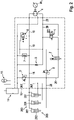
- figure 1 shows a circuit diagram of the drive unit according to the invention according to a first embodiment.
- a control block 12 is flanged to the controllable and speed-variable drive unit consisting of an electric motor M 1 and a pump 4 .
- the control block 12 contains all valves for the function and for the safety requirements.
- the electric motor M 1 is a synchronous motor or an asynchronous motor with a frequency converter for variable-speed drive
- the pump 4 is suitable for changing the direction of rotation (4-quarant operation) such as an axial piston pump with a constant displacement
- the control block 12 has a modular structure depending on the requirements.
- a cylindrical tube is attached to the control block 12, which is closed on one side by the control block 12 and on the other side of which a cylinder base is provided.
- a piston is installed in the low-pressure accumulator 14 as a separating element between the pressure medium of the drive unit and compressed air, similar to a piston accumulator.
- the cylindrical space is used for the variable and prestressed tank volume or as a low-pressure accumulator 14 for a differential volume of a three-surface cylinder 100 and is designed depending on the differential volume.
- the low-pressure accumulator 14 is preloaded by an external compressed air tank 16 with approximately 1.5 to 3 bar. Depending on the difference in volume, this can be a commercially available compressed air tank.
- a position switch (not shown) for the piston of the low-pressure accumulator 14 can be used as a level indicator for the pressure medium.
- the low-pressure accumulator 14 is connected to a cooler 24, which has a fan wheel driven by an electric motor M 2 .
- the cooler 24 is connected via a throttle to a branch 26 , which is connected to the return line 20 via a check valve 10 and via the counterbalance valve 6 .
- the check valve 10 is preloaded with 0.2 bar, for example.
- the counterbalance valve 6 opens at a pressure which corresponds to the pressure of the weight of the upper part of the press plus, for example, 10%.
- a pressure cylinder arrangement designed as a three-surface cylinder 100 is connected to the control block 12 .
- the three-surface cylinder 100 has a pressing chamber 101, which acts downwards in the pressing direction and is designed as an annular pressing chamber, a rapid traverse chamber 103, which also acts downwards, and an annular retraction chamber 102, which acts upwards in the retraction direction
- Three-surface cylinder 100 also has a central stationary piston, on the outer circumference of which a hollow piston 104 is movably arranged.
- a press head (not shown) is coupled to a lower end portion of the hollow piston 104 .
- the rapid motion chamber 103 is arranged in the hollow piston 104 in the region of its end section and is delimited at the top by the stationary piston.
- the retraction chamber 102 is arranged on the outer circumference of the hollow piston 104 .
- the pressing chamber 101 is arranged on the outer circumference of one of the stationary pistons or on the outer circumference of its stationary piston rod.
- a piston collar of the movable hollow piston 104 separates the compression chamber 101 from the rapid travel chamber 103.
- a pump connection 4A on the pressure side of the pump 4 is connected to the pressure chamber 101 via a pressure line 18 .
- a pull-back side pump port 4B is connected to the pull-back chamber 102 via a pull-back line 20 .
- a sequence valve 3 is arranged in the pressure line 18 between the respective connection points for an anti-cavitation valve 7 and a relief valve 8 .
- a rapid travel line 22 branches off from the compression line 18 , which is connected to the rapid travel chamber 103 .
- the rapid traverse chamber 103 alone is pressurized.
- the pressing chamber 101 is switched on via the switching valve 3 .
- the retraction chamber 102 alone is pressurized.
- the retraction chamber 102 remains pretensioned with the counter pressure.
- the small difference in quantity causes only slight heating (power loss) at the relief valve 8.
- the transition from rapid traverse to pressing can be precisely controlled with pretension in the retraction chamber 102, despite the weight of the upper part of the press.
- a directional control valve 1 which, in a first switching position preloaded by a spring, blocks the return chamber 102 from the pump connection 4B on the return side and thereby connects the pump connections 4A, 4B to one another. In a second switching position that can be switched by an electric actuator, the retraction chamber 102 is connected to the pump connection 4B on the retraction side.
- the pump 4 conveys the pressure medium from the retraction chamber 102 into the rapid traverse chamber 103 by means of a variable-speed drive.
- the low-pressure accumulator 14 absorbs the differential quantity.
- the pressure medium for the press chamber 101 is sucked in from the low-pressure accumulator 14 via the suction valve 7 .
- the rapid traverse "lowering the upper part of the press” thus takes place using the weight of the upper part of the press, but is controlled via the speed of the pump 4 with a preload that is defined by the compressed air tank 16 .
- the pressing chamber 101 For pressing (after reaching a lower rapid traverse position) the pressing chamber 101 is switched on via the switching valve 3 .
- the target position of the upper part of the press is controlled by the electric motor M1, with suction valves 7 , 9 on both sides being able to make up suction as required.
- the anti-cavitation valve 7 is designed as a non-return valve that can be opened and is arranged between the low-pressure accumulator 14 or the cooler 24 and the pressure line 18 .
- the back-pressure valve 9 is arranged between the low-pressure accumulator 14 or the cooler 24 and the return line 20 and is preloaded with, for example, 0.5 bar.
- the direction of rotation of the electric motor M 1 is changed for decompression.
- the excess quantity from the compression chamber 101 and the rapid traverse chamber 103 is discharged via the relief valve 8 before the counterbalance valve 6 opens for the counterbalance pressure.
- the control ratio (opening pressure without control pressure on the return side divided by opening pressure with control pressure on the return side) at the relief valve 8 is set in such a way that the relief valve 8 limits the maximum pressing pressure (like a pressure-limiting valve) without control pressure on the return side.
- the control pressure on the return side which corresponds at most to the pressure of the weight force, ie is smaller than the opening pressure at the counterbalance valve 6 , the compression pressure is lowered to a pre-opening pressure for the suction valve 7 .
- the standard property of a lowering brake valve is used, which requires a lower pilot pressure at higher load pressures.
- the relief valve 8 is therefore used to protect against excess pressure and at the same time as a pre-opening for the anti-cavitation valve 7. A controlled decompression of the compression chamber 101 and the rapid traverse chamber 103 is thus possible.
- the "Open press” rapid traverse is comparable to pressing but with a different direction of rotation of the electric motor M.
- FIG 2 shows a circuit diagram of the drive unit according to the invention according to a second embodiment. Only the differences from the first exemplary embodiment are explained below.
- the press cylinder arrangement 200 has a first differential cylinder 203 and two further differential cylinders. An annular chamber of the first differential cylinder 203 forms the retraction chamber 202, and the three Piston head chambers of the differential cylinders together form the compression chamber 201. The three piston head chambers are therefore connected to the compression line 18 together.
- the rapid-traverse chamber and the corresponding rapid-traverse line and sequence valve have been omitted.
- the anti-cavitation valve 7 is connected to the pressure line 18.
- the cooler has been omitted. Therefore, the throttle, the branch and the check valve are omitted.
- the annular spaces of the two other differential cylinders are used in addition to the low-pressure accumulator 14 as an accumulator for differential pressure medium. For this purpose, they are connected to the low-pressure accumulator 14 via a line 207 .
- a hydraulic drive unit for a press with a press cylinder assembly having one or more press chambers and a retraction chamber 102 is disclosed.
- a rapid traverse chamber 103 can also be provided.
- the drive unit has a variable-speed pump unit.
- a compression-side pump connection 4A can be connected or is connected to the compression chamber via a compression line 18
- a retraction-side pump connection 4B can be or is connected to the retraction chamber 102 via a retraction line 20 .
- a preloaded low-pressure accumulator 14 and the pump unit are attached to a control block 12 .
Landscapes
- Engineering & Computer Science (AREA)
- Mechanical Engineering (AREA)
- Physics & Mathematics (AREA)
- Fluid Mechanics (AREA)
- General Engineering & Computer Science (AREA)
- Fluid-Pressure Circuits (AREA)
Applications Claiming Priority (1)
| Application Number | Priority Date | Filing Date | Title |
|---|---|---|---|
| DE102021200096.7A DE102021200096A1 (de) | 2021-01-08 | 2021-01-08 | Hydraulische Antriebseinheit für eine Presse |
Publications (1)
| Publication Number | Publication Date |
|---|---|
| EP4026689A1 true EP4026689A1 (fr) | 2022-07-13 |
Family
ID=79024735
Family Applications (1)
| Application Number | Title | Priority Date | Filing Date |
|---|---|---|---|
| EP21217269.6A Withdrawn EP4026689A1 (fr) | 2021-01-08 | 2021-12-23 | Unité d'entraînement hydraulique pour une presse |
Country Status (3)
| Country | Link |
|---|---|
| EP (1) | EP4026689A1 (fr) |
| JP (1) | JP2022107534A (fr) |
| DE (1) | DE102021200096A1 (fr) |
Citations (6)
| Publication number | Priority date | Publication date | Assignee | Title |
|---|---|---|---|---|
| US6240758B1 (en) * | 1999-06-21 | 2001-06-05 | Toyokoki Co., Ltd. | Hydraulic machine |
| DE102009052531A1 (de) * | 2009-11-11 | 2011-05-12 | Hoerbiger Automatisierungstechnik Holding Gmbh | Maschinenpresse |
| DE102014218886B3 (de) * | 2014-09-19 | 2015-11-12 | Voith Patent Gmbh | Hydraulischer Antrieb mit Eilhub und Lasthub |
| EP3098457A1 (fr) * | 2015-05-27 | 2016-11-30 | Robert Bosch Gmbh | Actionneur linéaire hydrostatique et dispositif avec actionneurs linéaires hydrostatiques |
| DE102015211796A1 (de) * | 2015-06-25 | 2016-12-29 | Robert Bosch Gmbh | Hydraulisches System zur Druckmittelversorgung eines Hydrozylinders mit drei getrennten druckmittelbeaufschlagbaren Wirkflächen und Verfahren zum Betreiben des hydraulischen Systems |
| DE102017219084A1 (de) * | 2017-10-11 | 2019-04-11 | Robert Bosch Gmbh | Elektrohydraulisches System mit einer hydraulischen Achse und mindestens einem geschlossenen Hydraulikkreislauf |
-
2021
- 2021-01-08 DE DE102021200096.7A patent/DE102021200096A1/de not_active Withdrawn
- 2021-12-23 EP EP21217269.6A patent/EP4026689A1/fr not_active Withdrawn
-
2022
- 2022-01-07 JP JP2022001727A patent/JP2022107534A/ja active Pending
Patent Citations (6)
| Publication number | Priority date | Publication date | Assignee | Title |
|---|---|---|---|---|
| US6240758B1 (en) * | 1999-06-21 | 2001-06-05 | Toyokoki Co., Ltd. | Hydraulic machine |
| DE102009052531A1 (de) * | 2009-11-11 | 2011-05-12 | Hoerbiger Automatisierungstechnik Holding Gmbh | Maschinenpresse |
| DE102014218886B3 (de) * | 2014-09-19 | 2015-11-12 | Voith Patent Gmbh | Hydraulischer Antrieb mit Eilhub und Lasthub |
| EP3098457A1 (fr) * | 2015-05-27 | 2016-11-30 | Robert Bosch Gmbh | Actionneur linéaire hydrostatique et dispositif avec actionneurs linéaires hydrostatiques |
| DE102015211796A1 (de) * | 2015-06-25 | 2016-12-29 | Robert Bosch Gmbh | Hydraulisches System zur Druckmittelversorgung eines Hydrozylinders mit drei getrennten druckmittelbeaufschlagbaren Wirkflächen und Verfahren zum Betreiben des hydraulischen Systems |
| DE102017219084A1 (de) * | 2017-10-11 | 2019-04-11 | Robert Bosch Gmbh | Elektrohydraulisches System mit einer hydraulischen Achse und mindestens einem geschlossenen Hydraulikkreislauf |
Also Published As
| Publication number | Publication date |
|---|---|
| DE102021200096A1 (de) | 2022-07-14 |
| JP2022107534A (ja) | 2022-07-21 |
Similar Documents
| Publication | Publication Date | Title |
|---|---|---|
| EP2498982B1 (fr) | Presse | |
| EP2732959B1 (fr) | Agencement d'entraînement hydraulique sans accumulateur de pression pour et avec un consommateur, notamment pour presse hydraulique, et procédé d'entraînement hydraulique sans accumulateur de pression d'un consommateur | |
| DE102012015118B3 (de) | Maschinenpresse | |
| EP2867009B1 (fr) | Presse | |
| AT509239B1 (de) | Antriebsvorrichtung für eine biegepresse | |
| DE102016124118B4 (de) | Hydraulischer Antrieb mit Eil- und Lasthub | |
| EP1780420B1 (fr) | Unité hydraulique d'alimentation en pression et unité de traitement électro-hydraulique | |
| WO2009033199A1 (fr) | Dispositif d'entraînement pour presse à cintrer | |
| WO2012062416A1 (fr) | Essieu hydraulique | |
| DE102014005352B4 (de) | Maschinenpresse | |
| EP3317088B1 (fr) | Unité d'entraînement hydroélectrique | |
| EP3491253A1 (fr) | Système d'entraînement électro-hydrostatique | |
| EP2722165A2 (fr) | Circuit hydraulique pour un axe hydraulique et axe hydraulique | |
| DE102013224657A1 (de) | Hydraulische Anordnung | |
| DE102021212944B3 (de) | Hydraulische Schaltung mit einem Hydrozylinder | |
| EP4004370B1 (fr) | Dispositif de soupape pour un compresseur à piston | |
| EP3356683B1 (fr) | Actionneur électrohydraulique | |
| WO2014166935A2 (fr) | Presse hydraulique | |
| EP1387090B1 (fr) | Dispositif à actionnement hydraulique | |
| DE102016009416A1 (de) | Energieeffiziente Presse mit stabiler Stößelführung | |
| EP1564414B1 (fr) | Dispositif de commande hydraulique | |
| EP4026689A1 (fr) | Unité d'entraînement hydraulique pour une presse | |
| EP3895884B1 (fr) | Entraînement linéaire hydraulique | |
| EP3523120B1 (fr) | Groupe d'entraînement électo-hydraulique | |
| DD274385A1 (de) | Schaltungsanordnung zur steuerung des schnellen vor- und ruecklaufes von pressenstempeln, insbesondere an hydraulischen hochdruckpressen |
Legal Events
| Date | Code | Title | Description |
|---|---|---|---|
| PUAI | Public reference made under article 153(3) epc to a published international application that has entered the european phase |
Free format text: ORIGINAL CODE: 0009012 |
|
| STAA | Information on the status of an ep patent application or granted ep patent |
Free format text: STATUS: THE APPLICATION HAS BEEN PUBLISHED |
|
| AK | Designated contracting states |
Kind code of ref document: A1 Designated state(s): AL AT BE BG CH CY CZ DE DK EE ES FI FR GB GR HR HU IE IS IT LI LT LU LV MC MK MT NL NO PL PT RO RS SE SI SK SM TR |
|
| STAA | Information on the status of an ep patent application or granted ep patent |
Free format text: STATUS: THE APPLICATION IS DEEMED TO BE WITHDRAWN |
|
| 18D | Application deemed to be withdrawn |
Effective date: 20230114 |