EP4026778A2 - Procédé et dispositif pour emballer des verres creux - Google Patents
Procédé et dispositif pour emballer des verres creux Download PDFInfo
- Publication number
- EP4026778A2 EP4026778A2 EP21215091.6A EP21215091A EP4026778A2 EP 4026778 A2 EP4026778 A2 EP 4026778A2 EP 21215091 A EP21215091 A EP 21215091A EP 4026778 A2 EP4026778 A2 EP 4026778A2
- Authority
- EP
- European Patent Office
- Prior art keywords
- packaging
- hollow glass
- hollow
- conveyor belt
- glasses
- Prior art date
- Legal status (The legal status is an assumption and is not a legal conclusion. Google has not performed a legal analysis and makes no representation as to the accuracy of the status listed.)
- Withdrawn
Links
- 239000011521 glass Substances 0.000 title claims abstract description 385
- 238000004806 packaging method and process Methods 0.000 title claims abstract description 260
- 238000000034 method Methods 0.000 title claims abstract description 47
- 230000005484 gravity Effects 0.000 claims description 10
- 238000012856 packing Methods 0.000 description 11
- 230000002093 peripheral effect Effects 0.000 description 9
- 230000008859 change Effects 0.000 description 8
- 230000035622 drinking Effects 0.000 description 6
- 230000008569 process Effects 0.000 description 6
- 230000007547 defect Effects 0.000 description 5
- 239000000463 material Substances 0.000 description 4
- 238000012858 packaging process Methods 0.000 description 4
- 238000011144 upstream manufacturing Methods 0.000 description 4
- 239000011111 cardboard Substances 0.000 description 3
- 238000007796 conventional method Methods 0.000 description 3
- 238000001514 detection method Methods 0.000 description 3
- 230000000694 effects Effects 0.000 description 3
- 238000004519 manufacturing process Methods 0.000 description 3
- 238000006748 scratching Methods 0.000 description 3
- 230000002393 scratching effect Effects 0.000 description 3
- 239000011796 hollow space material Substances 0.000 description 2
- 230000003993 interaction Effects 0.000 description 2
- 239000007788 liquid Substances 0.000 description 2
- 230000007257 malfunction Effects 0.000 description 2
- 239000002184 metal Substances 0.000 description 2
- 230000003287 optical effect Effects 0.000 description 2
- 239000000123 paper Substances 0.000 description 2
- 239000004033 plastic Substances 0.000 description 2
- 239000000126 substance Substances 0.000 description 2
- 230000009471 action Effects 0.000 description 1
- 230000006735 deficit Effects 0.000 description 1
- 230000001419 dependent effect Effects 0.000 description 1
- 230000002349 favourable effect Effects 0.000 description 1
- 230000006872 improvement Effects 0.000 description 1
- 238000005457 optimization Methods 0.000 description 1
- 238000005192 partition Methods 0.000 description 1
- 238000000926 separation method Methods 0.000 description 1
- 239000002023 wood Substances 0.000 description 1
Images




Classifications
-
- B—PERFORMING OPERATIONS; TRANSPORTING
- B65—CONVEYING; PACKING; STORING; HANDLING THIN OR FILAMENTARY MATERIAL
- B65B—MACHINES, APPARATUS OR DEVICES FOR, OR METHODS OF, PACKAGING ARTICLES OR MATERIALS; UNPACKING
- B65B5/00—Packaging individual articles in containers or receptacles, e.g. bags, sacks, boxes, cartons, cans, jars
- B65B5/10—Filling containers or receptacles progressively or in stages by introducing successive articles, or layers of articles
- B65B5/101—Filling containers or receptacles progressively or in stages by introducing successive articles, or layers of articles by gravity
-
- B—PERFORMING OPERATIONS; TRANSPORTING
- B07—SEPARATING SOLIDS FROM SOLIDS; SORTING
- B07C—POSTAL SORTING; SORTING INDIVIDUAL ARTICLES, OR BULK MATERIAL FIT TO BE SORTED PIECE-MEAL, e.g. BY PICKING
- B07C5/00—Sorting according to a characteristic or feature of the articles or material being sorted, e.g. by control effected by devices which detect or measure such characteristic or feature; Sorting by manually actuated devices, e.g. switches
- B07C5/34—Sorting according to other particular properties
- B07C5/342—Sorting according to other particular properties according to optical properties, e.g. colour
-
- B—PERFORMING OPERATIONS; TRANSPORTING
- B65—CONVEYING; PACKING; STORING; HANDLING THIN OR FILAMENTARY MATERIAL
- B65B—MACHINES, APPARATUS OR DEVICES FOR, OR METHODS OF, PACKAGING ARTICLES OR MATERIALS; UNPACKING
- B65B21/00—Packaging or unpacking of bottles
- B65B21/02—Packaging or unpacking of bottles in or from preformed containers, e.g. crates
- B65B21/08—Introducing or removing single bottles, or groups of bottles, e.g. for progressive filling or emptying of containers
- B65B21/10—Introducing or removing single bottles, or groups of bottles, e.g. for progressive filling or emptying of containers using gravity flow
-
- B—PERFORMING OPERATIONS; TRANSPORTING
- B65—CONVEYING; PACKING; STORING; HANDLING THIN OR FILAMENTARY MATERIAL
- B65B—MACHINES, APPARATUS OR DEVICES FOR, OR METHODS OF, PACKAGING ARTICLES OR MATERIALS; UNPACKING
- B65B35/00—Supplying, feeding, arranging or orientating articles to be packaged
- B65B35/10—Feeding, e.g. conveying, single articles
- B65B35/24—Feeding, e.g. conveying, single articles by endless belts or chains
-
- B—PERFORMING OPERATIONS; TRANSPORTING
- B65—CONVEYING; PACKING; STORING; HANDLING THIN OR FILAMENTARY MATERIAL
- B65B—MACHINES, APPARATUS OR DEVICES FOR, OR METHODS OF, PACKAGING ARTICLES OR MATERIALS; UNPACKING
- B65B35/00—Supplying, feeding, arranging or orientating articles to be packaged
- B65B35/56—Orientating, i.e. changing the attitude of, articles, e.g. of non-uniform cross-section
- B65B35/58—Turning articles by positively-acting means, e.g. to present labelled portions in uppermost position
-
- B—PERFORMING OPERATIONS; TRANSPORTING
- B65—CONVEYING; PACKING; STORING; HANDLING THIN OR FILAMENTARY MATERIAL
- B65B—MACHINES, APPARATUS OR DEVICES FOR, OR METHODS OF, PACKAGING ARTICLES OR MATERIALS; UNPACKING
- B65B39/00—Nozzles, funnels or guides for introducing articles or materials into containers or wrappers
- B65B39/007—Guides or funnels for introducing articles into containers or wrappers
-
- B—PERFORMING OPERATIONS; TRANSPORTING
- B65—CONVEYING; PACKING; STORING; HANDLING THIN OR FILAMENTARY MATERIAL
- B65B—MACHINES, APPARATUS OR DEVICES FOR, OR METHODS OF, PACKAGING ARTICLES OR MATERIALS; UNPACKING
- B65B43/00—Forming, feeding, opening or setting-up containers or receptacles in association with packaging
- B65B43/42—Feeding or positioning bags, boxes, or cartons in the distended, opened, or set-up state; Feeding preformed rigid containers, e.g. tins, capsules, glass tubes, glasses, to the packaging position; Locating containers or receptacles at the filling position; Supporting containers or receptacles during the filling operation
- B65B43/54—Means for supporting containers or receptacles during the filling operation
- B65B43/56—Means for supporting containers or receptacles during the filling operation movable stepwise to position container or receptacle for the reception of successive increments of contents
-
- B—PERFORMING OPERATIONS; TRANSPORTING
- B65—CONVEYING; PACKING; STORING; HANDLING THIN OR FILAMENTARY MATERIAL
- B65B—MACHINES, APPARATUS OR DEVICES FOR, OR METHODS OF, PACKAGING ARTICLES OR MATERIALS; UNPACKING
- B65B57/00—Automatic control, checking, warning, or safety devices
- B65B57/10—Automatic control, checking, warning, or safety devices responsive to absence, presence, abnormal feed, or misplacement of articles or materials to be packaged
- B65B57/14—Automatic control, checking, warning, or safety devices responsive to absence, presence, abnormal feed, or misplacement of articles or materials to be packaged and operating to control, or stop, the feed of articles or material to be packaged
-
- B—PERFORMING OPERATIONS; TRANSPORTING
- B65—CONVEYING; PACKING; STORING; HANDLING THIN OR FILAMENTARY MATERIAL
- B65B—MACHINES, APPARATUS OR DEVICES FOR, OR METHODS OF, PACKAGING ARTICLES OR MATERIALS; UNPACKING
- B65B59/00—Arrangements to enable machines to handle articles of different sizes, to produce packages of different sizes, to vary the contents of packages, to handle different types of packaging material, or to give access for cleaning or maintenance purposes
- B65B59/001—Arrangements to enable adjustments related to the product to be packaged
-
- B—PERFORMING OPERATIONS; TRANSPORTING
- B65—CONVEYING; PACKING; STORING; HANDLING THIN OR FILAMENTARY MATERIAL
- B65B—MACHINES, APPARATUS OR DEVICES FOR, OR METHODS OF, PACKAGING ARTICLES OR MATERIALS; UNPACKING
- B65B65/00—Details peculiar to packaging machines and not otherwise provided for; Arrangements of such details
- B65B65/003—Packaging lines, e.g. general layout
- B65B65/006—Multiple parallel packaging lines
-
- B—PERFORMING OPERATIONS; TRANSPORTING
- B65—CONVEYING; PACKING; STORING; HANDLING THIN OR FILAMENTARY MATERIAL
- B65G—TRANSPORT OR STORAGE DEVICES, e.g. CONVEYORS FOR LOADING OR TIPPING, SHOP CONVEYOR SYSTEMS OR PNEUMATIC TUBE CONVEYORS
- B65G11/00—Chutes
- B65G11/12—Chutes pivotable
- B65G11/123—Chutes pivotable for articles
-
- B—PERFORMING OPERATIONS; TRANSPORTING
- B65—CONVEYING; PACKING; STORING; HANDLING THIN OR FILAMENTARY MATERIAL
- B65G—TRANSPORT OR STORAGE DEVICES, e.g. CONVEYORS FOR LOADING OR TIPPING, SHOP CONVEYOR SYSTEMS OR PNEUMATIC TUBE CONVEYORS
- B65G47/00—Article or material-handling devices associated with conveyors; Methods employing such devices
- B65G47/34—Devices for discharging articles or materials from conveyor
- B65G47/44—Arrangements or applications of hoppers or chutes
-
- B—PERFORMING OPERATIONS; TRANSPORTING
- B65—CONVEYING; PACKING; STORING; HANDLING THIN OR FILAMENTARY MATERIAL
- B65G—TRANSPORT OR STORAGE DEVICES, e.g. CONVEYORS FOR LOADING OR TIPPING, SHOP CONVEYOR SYSTEMS OR PNEUMATIC TUBE CONVEYORS
- B65G11/00—Chutes
- B65G11/02—Chutes of straight form
- B65G11/023—Chutes of straight form for articles
-
- B—PERFORMING OPERATIONS; TRANSPORTING
- B65—CONVEYING; PACKING; STORING; HANDLING THIN OR FILAMENTARY MATERIAL
- B65G—TRANSPORT OR STORAGE DEVICES, e.g. CONVEYORS FOR LOADING OR TIPPING, SHOP CONVEYOR SYSTEMS OR PNEUMATIC TUBE CONVEYORS
- B65G11/00—Chutes
- B65G11/08—Chutes with discontinuous guiding surfaces, e.g. arranged in zigzag or cascade formation
- B65G11/081—Chutes with discontinuous guiding surfaces, e.g. arranged in zigzag or cascade formation for articles
-
- B—PERFORMING OPERATIONS; TRANSPORTING
- B65—CONVEYING; PACKING; STORING; HANDLING THIN OR FILAMENTARY MATERIAL
- B65G—TRANSPORT OR STORAGE DEVICES, e.g. CONVEYORS FOR LOADING OR TIPPING, SHOP CONVEYOR SYSTEMS OR PNEUMATIC TUBE CONVEYORS
- B65G11/00—Chutes
- B65G11/16—Interior surfaces; Linings
- B65G11/163—Interior surfaces; Linings for articles
-
- B—PERFORMING OPERATIONS; TRANSPORTING
- B65—CONVEYING; PACKING; STORING; HANDLING THIN OR FILAMENTARY MATERIAL
- B65G—TRANSPORT OR STORAGE DEVICES, e.g. CONVEYORS FOR LOADING OR TIPPING, SHOP CONVEYOR SYSTEMS OR PNEUMATIC TUBE CONVEYORS
- B65G11/00—Chutes
- B65G11/20—Auxiliary devices, e.g. for deflecting, controlling speed of, or agitating articles or solids
- B65G11/203—Auxiliary devices, e.g. for deflecting, controlling speed of, or agitating articles or solids for articles
-
- B—PERFORMING OPERATIONS; TRANSPORTING
- B65—CONVEYING; PACKING; STORING; HANDLING THIN OR FILAMENTARY MATERIAL
- B65G—TRANSPORT OR STORAGE DEVICES, e.g. CONVEYORS FOR LOADING OR TIPPING, SHOP CONVEYOR SYSTEMS OR PNEUMATIC TUBE CONVEYORS
- B65G47/00—Article or material-handling devices associated with conveyors; Methods employing such devices
- B65G47/22—Devices influencing the relative position or the attitude of articles during transit by conveyors
- B65G47/24—Devices influencing the relative position or the attitude of articles during transit by conveyors orientating the articles
- B65G47/248—Devices influencing the relative position or the attitude of articles during transit by conveyors orientating the articles by turning over or inverting them
Definitions
- the present invention relates to a method and a system for packaging hollow glasses, in particular drinking glasses, in particular for introducing or sorting said glasses into transport packaging such as cardboard boxes.
- Conventional methods for packaging hollow glasses are generally used subsequent to a manufacturing process of hollow glasses, in which hollow glasses are conveyed on a conveyor belt to a packaging system.
- Conventional methods for packaging hollow glass use a robot which lifts hollow glass from the conveyor belt and inserts or inserts it into a package.
- the robot which in conventional packaging processes lifts hollow glasses from a conveyor belt and inserts them into a package, uses a suction device, for example, which is used to suck hollow glasses, for example at the drinking rim, then lift the hollow glasses in order to then guide the hollow glasses into the packaging.
- the conventional method described above is repeated until a package is filled with hollow glasses.
- the above conventional packaging method has various problems.
- the robot which gradually lifts the hollow glass with suction, guides it into a package and then releases the hollow glass again by interrupting suction, causes a long process time for the packaging of hollow glass.
- the robot which has a suction device, can be a source of various errors or malfunctions, which additionally delay the packaging process if an error or malfunction occurs.
- the present method for packaging hollow glass advantageously allows, through the sliding guidance of the at least one hollow glass from the discharge end of the conveyor belt into the packaging by means of a guide device, that no robot, in particular no robot with a suction device, is required for packaging hollow glass, which creates sources of error can be reduced or avoided. Furthermore, the present method for packaging hollow glasses advantageously enables hollow glasses to be guided en masse one after the other and sliding into a package, as a result of which a particularly short process time for the packaging of hollow glasses can be achieved. Thus, based on the present invention, an improved method for packaging hollow glass can be provided.
- the guide device can be movable, the guide device being moved after the at least one hollow glass has been slidably guided into the packaging and before further hollow jars are slidably guided into the packaging.
- the guide device can be movable both perpendicularly or transversely to the conveying direction of the conveyor belt and also be movable along the conveying direction of the conveyor belt.
- a movable guide device advantageously makes it possible to slide a large number of hollow glasses one after the other into a package, with a package being able to be filled with hollow glasses within a short time.
- the packaging can be movable, the packaging being moved after the at least one hollow glass has been slid into the packaging and before further hollow jars have been slid into the packaging.
- the packaging can be movable both perpendicularly or transversely to the conveying direction of the conveyor belt and also be movable along the conveying direction of the conveyor belt.
- Movable packaging advantageously makes it possible to slide a large number of hollow glasses into the packaging one after the other, with the packaging being able to be filled with hollow glasses within a short time.
- both the guide device and the packaging can be movable.
- neither the guide device can be movable, nor can the packaging be movable.
- the guiding device can be configured to guide a certain number of hollow glasses next to one another in a sliding manner.
- the guide device can be configured to guide 1, 2, 3, 4, 5, 6 or more hollow glasses next to one another in a sliding manner.
- the guide device can have multiple guide rails to the at least one For example, to slide hollow glass between two guide rails.
- Hollow glass describes a glass, in particular a glass vessel, which has a cavity that can be filled or partially filled with one or more liquids or other substances, for example.
- Examples of hollow glasses can be drinking glasses, jugs, bottles, vases and other glasses that have a cavity.
- the conveying direction describes a direction in which an element lying on the conveyor belt is conveyed.
- the conveying direction runs essentially parallel to a conveyor belt surface and points towards a discharge end of the conveyor belt.
- the conveying direction in relation to the conveyor belt can, in particular, essentially correspond to a longitudinal direction of the packaging.
- Transverse direction describes a direction at right angles to the conveying direction.
- the transverse direction describes a direction that runs essentially parallel to a conveyor belt surface and essentially perpendicular to the conveying direction.
- the transverse direction in relation to the conveyor belt can, in particular, essentially correspond to a width direction of the packaging.
- the vertical direction describes a direction that extends essentially upwards from the conveyor belt.
- the vertical direction can in particular be essentially perpendicular to the conveying direction and to the transverse direction.
- the conveying direction, the transverse direction and the vertical direction can in particular form a right-hand system.
- the terms gliding and gliding guidance refer here mostly to a movement of the hollow glass.
- the hollow glass moves essentially due to its weight along a guide device or a sliding surface of a guide device.
- the sliding or the sliding guidance of a hollow glass thus describes a movement of the hollow glass, which is influenced on the one hand by the weight of the hollow glass and on the other hand is influenced by the friction, in particular by the sliding friction, which occurs between the hollow glass and, for example, a sliding surface of a guide device.
- the conveyor belt as described here can in particular be a typical conveyor belt mounted on rollers, in particular an endless conveyor belt, in particular with a continuous conveying surface extending between two essentially oppositely arranged deflection devices for conveying the hollow glasses.
- the conveyor belt can comprise other conveyor links and/or conveyor chains which are suitable for conveying hollow glasses.
- the conveyor belt can be formed by a large number of conveyor rollers arranged in a row, which are configured to convey hollow glasses to a distal conveyor roller in such a way that the hollow glasses preferably leave the conveyor belt at or in the region of the distal conveyor roller.
- the lined-up conveyor rollers can be driven or at least partially non-driven, and can also be arranged horizontally next to each other or form an incline or gradient.
- the present packaging method can dispense with a robot, in particular a suction robot.
- the method can include a step of tipping the at least one hollow glass over the discharge end of the conveyor belt.
- the discharge end of the conveyor belt can in particular be formed by the conveyor belt running off at a deflection device, in particular at one or more deflection rollers.
- the method has a step of tipping the at least one hollow glass over a deflection device or deflection roller of the conveyor belt, preferably towards the guide device, which is configured to guide the at least one hollow glass in a sliding manner.
- the tilting of the at least one hollow glass over the discharge end of the conveyor belt can in particular be a passive tilting of the at least one hollow glass over the discharge end of the conveyor belt.
- Passive tilting of the at least one hollow glass means that the at least one hollow glass preferably tilts from the discharge end of the conveyor belt exclusively due to the weight of the at least one hollow glass.
- the passive tilting of the at least one hollow glass means that the at least one hollow glass tilts or is configured to tilt from the discharge end of the conveyor belt, preferably exclusively due to the curvature of the deflection device or deflection roller, in particular the round cross-section of the deflection roller.
- the passive tilting of the at least one hollow glass means that the at least one hollow glass preferably exclusively due to the change in a direction of movement of the conveyor belt at the deflection device, in particular the change in the direction of movement of the conveyor belt through the deflection device of at least about 60°, for example in a range from about 90° to about 180°, tilts or is configured to tilt.
- the deflection device can be configured that Direction of movement of the conveyor belt by at least about 60°, preferably in a range from about 60° to about 220°, more preferably in a range from about 90° to about 180°, in a plane spanned by a height direction and a conveying direction to incline or to change.
- the deflection device can be arranged in particular in the area of a conveying end, the conveying end characterizing the area of the conveyor belt in which the hollow glass is configured to leave the conveyor belt due to the change in the direction of movement of the conveyor belt.
- the packaging can have a plurality of packaging locations for a corresponding plurality of hollow glass, with the guide device and/or the packaging being movable, and with after the sliding guidance of the at least one hollow glass in the packaging and before at least one of the guide means and the package is moved relative to the discharge end of the conveyor belt upon sliding another hollow glass into the package.
- the packaging which has a plurality of packaging locations, with at least one of the guide device and the packaging being moved after a hollow glass has been slidably guided into the packaging and before another hollow glass is slidably guided into the packaging, enables a particularly fast and safe method be provided for packaging hollow glasses, which serves to fill a package with a plurality of packing places with hollow glasses.
- the packaging locations of the plurality of packaging locations can be separated from one another at least in sections by separating elements.
- Exemplary packaging can essentially consist of or have the following substances or materials: wood, cardboard, paper, plastic, metal.
- Exemplary dividers may include wooden sections, cardboard sections, Be paper sections, plastic sections or metal sections.
- the guiding device can be moved in a transverse direction relative to the Ejection end are moved, and from a state in which the packaging places are occupied in the width direction of the packaging with hollow glasses, the packaging is moved in the conveying direction relative to the ejection end.
- the guide device can be moved in a transverse direction relative to the discharge end. If the packaging positions of the packaging are occupied in the width direction, the packaging can be moved in the conveying direction relative to the discharge end after a hollow glass has been slid into the packaging and before another hollow glass has been slid into the packaging.
- the packaging can, for example, be moved essentially in the conveying direction towards the dropping end or away from the dropping end.
- moving the guide device in the transverse direction in order in particular to enable the packaging spaces of the pack to be completely occupied with hollow glasses in the width direction, allows the same guide device to be used to slide a large number of hollow glasses into the pack, so that the individual Hollow glasses are subject to essentially the same weight force when sliding. Therefore, by a possible Moving the guide means transversely can provide a constant action for sliding the jars into the package.
- the successive slidingly guided hollow glasses describe different movements driven by the weight of the hollow glasses during the sliding guidance and are thus guided into the packaging at speeds that differ greatly from one another.
- Speeds that differ greatly from one another mean, for example, deviations in which the speed at which two hollow glasses slide into the packaging has a ratio outside of 0.7 to 1.3, preferably outside of 0.8 to 1.2 and particularly preferably of about 0. 9 to 1.1.
- the above-described guide device which is movable in particular in the transverse direction, in conjunction with the packaging that is movable in particular in the conveying direction, advantageously enables a particularly constant and therefore safe and reliable process for packaging glasses to be provided.
- the guide device can in particular remain rigid or remain relative to the discharge end between the sliding guidance of a hollow glass into the packaging and the sliding guidance of a further hollow glass into the packaging.
- the packaging can be moved in the conveying direction and in the transverse direction in order to enable a packaging to be filled with hollow glasses in a reliable, safe and rapid manner.
- the guide device can be designed in several parts.
- the guide device can essentially have a fixed first partial guide section facing the discharge end of the conveyor belt and a movable second partial guide section facing the packaging.
- the first partial guide section and the second partial guide section can, for example, be plugged into one another and/or be connected by a joint and/or be configured at a distance from one another.
- a guide device which has a first guide section that is fixed relative to the discharge end and has a second guide section that is movable relative to the packaging, can be used to provide a particularly flexible guide device that enables a packaging to be filled advantageously reliably and quickly.
- the method of packaging jars may include a reorienting step prior to sliding to tilt at least some of the jars.
- the method for packaging hollow glasses can have a reorientation step before sliding the at least one hollow glass into the packaging in order to tilt hollow glasses.
- the reorientation step can precede the sliding guiding, in particular in the conveying direction of the conveyor belt.
- the reorientation step counter to the conveying direction or upstream of the conveying direction can precede the sliding guidance.
- the reorientation step can be carried out by means of a reorientation device, in which case the reorientation device can be placed in front of the guide device for sliding guidance in the conveying direction of the conveyor belt.
- hollow glasses that are tilted and not tilted can be conveyed to the guide device. Due to the differently oriented hollow glasses, which are conveyed to the guide device, the hollow glasses can in turn be placed in the packaging in a particularly space-saving manner, as a result of which a particularly advantageous method for packaging hollow glasses for resource-saving packaging of a large number of hollow glasses is provided.
- the guide device can have an entry opening facing the ejection end, which is configured so that only hollow glasses with a certain orientation can slide or be allowed into the guide device. Furthermore, by tilting some of the hollow glass by means of a reorientation step, for example, only tilted or non-tilted hollow glass can be guided slidingly through the guide device into the packaging, so that the other tilted or non-tilted hollow glasses are not caught by the guide device or .do not get into the sliding guidance of the guide device.
- tipped and non-tipped hollow jars can thus be used to distinguish between hollow jars with and without material defects or other quality differences or defects in order to identify hollow jars in the packaging process as rejects or as first choice and second choice.
- the reorientation device may be provided with a reorientation element, such as a rod.
- the reorientation device can use a predetermined program, a counter, and/or a recognition unit, such as an optical recognition system, to determine which hollow glasses are to be tilted, for example using a reorientation element.
- the reorientation device can set the height of a reorientation element for tilting or reorienting a hollow glass, for example by means of a height adjustment, so that the hollow glass tips over essentially against the conveying direction of the conveyor belt or essentially in the conveying direction of the conveyor belt.
- a tilted hollow glass describes a hollow glass which rests essentially on a hollow glass wall section, in particular on a hollow glass wall section on the conveyor belt.
- a non-tilted hollow glass describes a hollow glass which rests essentially on the hollow glass bottom or the hollow glass rim, in particular on the hollow glass bottom or the hollow glass rim on the conveyor belt.
- the hollow glasses can be conveyed alternately tilted and non-tilted to the step of sliding.
- the alternating conveyance of tilted and non-tilted hollow glasses to the step of sliding guidance allows hollow glasses to be slidably guided into the packaging in different orientations, whereby a particularly space-saving and resource-saving packaging of a large number of hollow glasses can be achieved.
- the hollow glasses can be conveyed alternately in the conveying direction and tilted counter to the conveying direction to the sliding guiding step.
- the hollow glass can be conveyed alternately tilted with the hollow glass base in front and with the hollow glass rim in front to the sliding guiding step.
- the conveying of tilted hollow glass alternately with hollow glass bottom first and hollow glass edge first enables differently oriented hollow glass to be guided into the packaging in a sliding manner, which enables a particularly advantageous, space-saving and resource-saving packaging of a large number of hollow glass.
- the hollow glasses which are tilted in a reorientation step, can be tilted by contact with a transverse element above a center of gravity of the respective hollow glass.
- the transverse element describes an exemplary reorientation element and can be a round rod, a polygonal rod or the like.
- the reorientation element can, for example, also consist of a plurality of transverse elements. If two transverse elements are used as the reorientation element, one of the two transverse elements can serve to be arranged in front of the hollow glass in the conveying direction and the other of the two transverse elements can be used during the reorientation step serve to be arranged behind the hollow glass in the conveying direction.
- the hollow glass can be tilted essentially in the conveying direction.
- the hollow glass can be tilted essentially counter to the conveying direction. While the use of two transverse elements allows the glass container to be smoothly guided into a tilted state, a single transverse element, with a movement according to the above-described speed relationship for two transverse elements, enables a glass container to be tilted reliably while providing a particularly simple structure.
- the hollow glasses which are tilted in a reorientation step, can be tilted by contact with a transverse element below a center of gravity of the respective hollow glass.
- Contact with a transverse element below a center of gravity of the respective hollow glass in order to tilt the hollow glass in the reorientation step is particularly suitable for tilting the hollow glass in the conveying direction.
- a transverse element can be configured by means of a height adjustment to contact hollow glasses both above a center of gravity of a hollow glass in question and to contact hollow glasses below a center of gravity of a hollow glass in question. Furthermore, contact between a transverse element and a hollow glass can be avoided by means of a height adjustment, in that the transverse element is adjusted to a height above the hollow glass.
- the reorientation step which can be carried out by means of various reorientation elements, in particular by means of one or more transverse elements, becomes a particularly simple one and at the same time a versatile packaging process is provided, which reliably and safely enables the reorientation of hollow glass and the associated advantages of space-saving and resource-saving packaging, as well as the suitability for sorting hollow glass with differences in quality during packaging.
- a plurality of guide devices can be arranged in the area of the discharge end, so that a corresponding number of hollow glasses can be slided side by side into the packaging.
- several guide devices can be arranged next to one another essentially in the transverse direction in the area of the discharge end of the conveyor belt, so that correspondingly several hollow glasses can be guided side by side in the transverse direction of the conveyor belt or in the width direction of the packaging and sliding into the packaging.
- the arrangement of a plurality of guide devices in the area of the dropping end makes it possible to guide a plurality of hollow glasses into the packaging at the same time and/or spatially, so that an advantageous method for the rapid packaging of a large number of hollow glasses is provided.
- a conveyor belt can have a plurality of discharge ends, at least one guide device being arranged at each discharge end of the plurality of discharge ends of the conveyor belt in order to guide at least one hollow glass slidably into a packaging.
- the guide device can comprise at least one guide tube, the longitudinal axis of which is curved in sections, and/or comprise at least one tube segment which does not have a closed circumference and whose longitudinal axis is curved in sections, and/or comprise at least one pair of guide rails, which can be curved in sections.
- a guide device which comprises at least one guide tube and/or a tube segment and/or a pair of guide rails, advantageously enables hollow glasses to be guided in a safe and precise sliding manner, while a robot for lifting hollow glasses into a package can be dispensed with .
- the exemplary guide devices described above advantageously enable the safe and precise sliding guidance of hollow glasses, in particular the safe and precise sliding guidance of essentially round hollow glasses, whereby the hollow glasses suitable for the present packaging method are not limited to this and can also have one or more edges.
- exemplary guide devices can include or be, in particular, polygonal guide tubes, guide rings and other elements or devices which have one or more sliding surfaces.
- the guide device can have a felt section and/or have a rubber section and/or have an air supply device that is configured to cause an air flow that slows down a slidingly guided hollow glass.
- the guide device has a felt section
- a guide device that is particularly cushioning and has particularly sliding properties can be provided, which is suitable for sliding hollow glass into a package without damaging it.
- the guide device can in particular be at least one guide tube or another guide device, which has a felt section in its entirety or in sections on the inner circumference in order to guide a hollow glass slidably into a packaging advantageously without damage. For example, scratching and other mechanical impairments of the hollow glass by the guide device can be prevented or avoided by means of a felt section on an inner peripheral side of a guide device.
- the guide device has a rubber section
- the guide device can in particular be at least one guide tube or another guide device, which has a rubber section in its entirety or in sections on the inner circumference in order to advantageously brake a hollow glass and slide it into a package without damaging it.
- only one end section of the guide device facing the packaging can have a rubber section on the inner circumference.
- a predetermined maximum speed at which a hollow glass is guided into a package can be defined by means of a predetermined rubber section on an inner peripheral side of a guide device.
- a guide device can be provided which is provided with targeted braking properties and is suitable for sliding hollow glass into a package without damaging it.
- the guide device can in particular be at least one guide tube or another guide device, with the air supply device on an end section facing the packaging Guide device is arranged so that a hollow glass can be specifically slowed down before being placed in a package. For example, by means of a predetermined air pressure and a predetermined direction of flow, a predetermined maximum speed can be defined at which a hollow glass is guided into a package.
- the guide device according to the embodiments described above is not limited to this and can have other different cushioning, rubbing, braking or also accelerating devices and sections in order to provide a specific method for packaging hollow glasses.
- the hollow glasses 10, as in figure 1 shown have a hollow glass rim 12 .
- the edge 12 of the hollow glass represents an opening of the hollow glass 10, as a result of which, for example, liquids can get into the hollow space of the hollow glass 10 or out of the hollow space of the hollow glass.
- the hollow glasses 10 can have a hollow glass bottom 14 and a hollow glass wall section 16, wherein the hollow glass bottom 14 can be configured flat or convex, for example.
- the hollow glass wall section 16 essentially extends between the hollow glass edge 12 and the hollow glass base 14 and can have any contour.
- the hollow glasses 10, as in figure 1 drinking glasses are indicated.
- Hollow glasses 10 according to the present invention can also be, for example, vases, bottles, jugs and other hollow glasses.
- a guiding device 30 is arranged in the area of the discharge end 22 , which is configured to guide the hollow glasses 10 from the conveyor belt 20 into a packaging 40 in a sliding manner.
- the guide device 30 can, as in figure 1 indicated by way of example, have an entry opening 31 so that the hollow glasses 10 can reach the guide device 30 from the conveyor belt 20 or via the discharge end 22 of the conveyor belt 20 through the entry opening 31 .
- the packaging system 1 can be configured to tip a hollow glass 10 at the discharge end 22 of the conveyor belt 20, in particular at the discharge end, by means of the deflection device arranged distally on the conveyor belt 20 in the conveying direction RF, which is formed, for example, by at least one deflection roller or one conveyor roller 22 to tip a hollow glass 10 from the conveyor belt 20 towards the guide device.
- the packaging system 1 causes the hollow glass 10 to leave the conveyor belt 20 at the discharge end 22 , in particular leaving it falling, with the hollow glass 10 more preferably falling toward or into the guide device 30 .
- the tipping of the at least one hollow glass 10 at the ejection end 22 or over the ejection end 22 of the conveyor belt 20 can be, in particular, a passive tipping of the at least one hollow glass 10 at the ejection end 22 or over the ejection end 22 of the conveyor belt 20.
- the passive tilting of at least a hollow glass 10, as shown by the figures 1 and 3 indicated by way of example means that the at least one hollow glass 10 tilts from the discharge end 22 of the conveyor belt 20 preferably exclusively due to the weight of the at least one hollow glass 10 .
- the passive tilting of the at least one hollow glass 10 means that the at least one hollow glass 10 tilts or falls away from the discharge end 22 of the conveyor belt 20, preferably exclusively due to the deflection of the conveyor belt at the deflection device or deflection roller, in particular the round cross-section of the deflection roller. is configured to flip.
- the hollow glass 10 moves essentially on the basis of the weight of the hollow glass 10 and the sliding friction between the hollow glass 10 and the guide device 30 that develops during sliding guidance.
- the interaction of the two components, the weight of the Hollow glass 10 and the sliding friction between the hollow glass 10 and the guide device 30, the hollow glass 10 is guided or slidably guided into the packaging 40.
- the outer circumference of the hollow glass 10 can come into contact with the inner circumference of the guide device 30 or only come into contact with a section of the inner circumference of the guide device 30 .
- the interaction of the two components, the weight of the hollow glass 10 and the sliding friction between the hollow glass 10 and the guide device 30 can be influenced or adjusted in particular by the geometry and surface of the guide device 30, so that in a particularly simple and resource-saving manner a favorable, reliable and accurate packaging system or method of packaging can be provided.
- the guide device 30 can be connected to the packaging system, for example, by means of a guide connection 38 . Furthermore, the guide device 30 can be moved by means of the guide connection 38, for example in the transverse direction F Q . Furthermore, the guide device 30 can be inclined by means of the guide connection 38 with respect to a vertical direction R H , in a plane spanned by the conveying direction R F and the vertical direction R H and/or in a plane spanned by the transverse direction R Q and the vertical direction H R .
- the packaging 40 can be used as in figure 1 indicated have any number of packaging spaces 42, such as six packaging spaces 42.
- the packaging 40 can in particular one, two, three, four, five, six, seven, eight, nine, ten, eleven, twelve, sixteen, have twenty, twenty-four, thirty, forty or more packing places 42.
- the packaging locations 42 of the packaging 40 can be separated from one another at least in sections, in particular by separating sections or separating means.
- the packaging 40 can have no partitions or separating means, so that the hollow glasses 10 in the packaging 40 adjoin or rest on neighboring hollow glasses 10, so that the packaging 40 can be filled with a specific maximum number of hollow glasses 10.
- the packaging 40 can in particular be provided at a packaging point 44, with the packaging 40 being movable on the packaging point 44 and/or the packaging point 44 itself.
- packaging 40 and packaging point 44 can be movable in a plane that is spanned by the longitudinal direction R L and the width direction R B .
- the longitudinal direction R L can in particular be a direction along which a side surface of the packaging 40 with the height direction H R spans.
- the longitudinal direction R L runs in view of figure 1 essentially from right to left, while the height direction H R represents a direction running essentially upwards or upwards.
- the width direction R B can in particular be a direction along which an adjoining side surface of the packaging 40 spans with the height direction H R , the adjoining side surface running essentially perpendicular to the side surface of the packaging which spans along the longitudinal direction R L .
- the longitudinal direction R L can essentially correspond to the conveying direction R F and the width direction R B im Essentially correspond to the transverse direction F Q.
- the longitudinal direction R L , the width direction R B and the vertical direction HR or the conveying direction RF , the transverse direction F Q and the vertical direction HR can each essentially describe a right-hand system, which, however, cannot be assigned a fixed origin on the packaging system 1 .
- the packaging point 44 can have a sensor for detecting the fill level of the packaging 40 with hollow glasses 10 .
- the packaging point 44 can have a weight sensor such as a spring balance, for example, in order to be able to detect the filling level of the packaging 40 with hollow glass 10 based on a specific weight of a hollow glass.
- a sensor at the packaging point 44 can be used to detect when a hollow glass 10 has been guided into the packaging 40 by the sliding guidance of the guide device 30, so that corresponding information can be transmitted to a packaging system controller, whereupon the packaging 40 can, for example, be moved and /or can be replaced at the packaging point 44 in particular by an unfilled packaging 40.
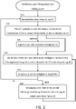
- step S30 in particular can be carried out optionally, so that an exemplary method for packaging hollow glasses 10 can have both a step of tipping one or more hollow glasses 10 and can also run without a step of tipping one or more hollow glasses 10.
- Step S50 describes a query in which it is checked whether the packaging 40 is filled with hollow glasses 10, ie the packaging 40 is full. Furthermore, in step S50 it can be checked in particular when or whether a hollow glass 10 was fed into the packaging 40 .
- the packing station 44 may include a sensor, such as a weight sensor, that detects the passage of a hollow glass 10 into the package 40 provided at the packing station 44 .
- the last case in which no hollow glass 10 was fed into the packaging 40 corresponds to a stand-by state, in which there is a wait for a hollow glass 10 to be fed into the packaging 40 .
- the packaging 40 is not filled with hollow glass 10, in other words packaging positions 42 in the packaging 40 are not yet occupied with hollow glass 10, a movement of the guide device 30 and /or the packaging 40 to be initiated.
- the movement of at least one of the guiding device 30 and the package 40 is enabled, as indicated by the loop from step S60 towards step S40 in figure 2 provided, the sliding guiding of at least one further hollow glass 10 into the packaging 40, in particular into a free packaging space 42 of the packaging 40.
- the present invention enables a particularly simple, resource-saving and at the same time safe and quick packaging of a large number of hollow glasses 10, which is particularly suitable for mass production, such as drinking glasses. Since no robot is used to pack the hollow glasses 10, in particular no vacuum robot is used, possible sources of error in the method of packing can be reduced, so that a particularly reliable method for packing hollow glasses 10 is still made possible.
- figure 3 shows another packaging system 1 for packaging hollow glasses 10 in a packaging 40.
- the packaging system 1, as in figure 3 shown, essentially corresponds to the exemplary packaging system 1 figure 1 , where according to figure 3 the packaging system 1 has in particular a reorientation device 50 .
- the reorientation device 50 can be arranged in the conveying direction F R of the conveyor belt 20 in particular upstream of the guide device 30 .
- the reorientation device 50 can be arranged on the conveyor belt 20 , with a hollow glass 10 conveyed on the conveyor belt 20 first passing the reorientation device 50 and then being conveyed further to the guide device 30 .
- a plurality of reorientation devices 50, detection devices or other sorting devices can be arranged on the conveyor belt 20, in particular arranged upstream of the guide device 30 on the conveyor belt 20.
- the reorientation device 50 can be used as in figure 3 shown in particular have a reorientation element 52 .
- the reorientation element 52 can be, for example, a crossbar or a crossbar.
- the reorientation element can also be a pair of transverse rods or crossbars or have another multiplicity of elements such as rods, which serve to enable a reorientation of a hollow glass 10 .
- a hollow glass 10 or several hollow glasses 10 can be tilted by means of the reorientation element 52 .
- a hollow glass 10 can be tilted forwards or backwards in the conveying direction R F by means of the reorientation element 52 .
- Tilting a hollow glass 10 forward in the conveying direction R F leads to a reorientation of the hollow glass 10 so that the hollow glass 10 rests with a hollow glass wall section 16 on the conveyor belt 20 and is oriented with the hollow glass edge 12 first essentially in the conveying direction R F .
- tilting a hollow glass 10 backwards in the conveying direction R F leads to a reorientation of the hollow glass 10, so that the hollow glass 10 rests with a hollow glass wall section 16 on the conveyor belt 20 and is oriented with the hollow glass bottom 14 in front essentially in the conveying direction R F.
- a tipping of a hollow glass 10 forward in the conveying direction R F can be brought about, for example, by means of a reorientation element 52, which is arranged above the center of gravity of the hollow glass 10 to reorient the hollow glass 10 in the height direction R H and is moved forward in the conveying direction R F , in particular faster than that Conveyor belt 20 is moved forward in the conveying direction R F .
- a tipping of a hollow glass 10 forward in the conveying direction R F can be brought about, for example, by means of a reorientation element 52, which is arranged below the center of gravity of the hollow glass 10 in order to reorient the hollow glass 10 in the height direction R H and is not moved in the conveying direction R F or in the conveying direction R F is moved backwards.
- a reorientation element 52 which is arranged below the center of gravity of the hollow glass 10 in order to reorient the hollow glass 10 in the height direction R H and is not moved in the conveying direction R F or in the conveying direction R F is moved backwards.
- a reorientation element 52 which is arranged below the center of gravity of the hollow glass 10 in order to reorient the hollow glass 10 in the height direction R H and is not moved in the conveying direction R F or in the conveying direction R F is moved backwards.
- there are other options for causing a hollow glass 10 to tilt forward in the conveying direction R F such as by guiding it using
- a tipping of a hollow glass 10 backwards in the conveying direction R F can be brought about, for example, by means of a reorientation element 52, which is arranged above the center of gravity of the hollow glass 10 in order to reorient the hollow glass 10 in the height direction R H and is not moved in the conveying direction R F or in the conveying direction R F is moved backwards.
- a tipping of a hollow glass 10 backwards in the conveying direction R F can be brought about, for example, by means of a reorientation element 52, which is arranged below the center of gravity of the hollow glass 10 in order to reorient the hollow glass 10 in the height direction R H and is moved forwards in the conveying direction R F , in particular faster as the conveyor belt 20 is advanced in the conveying direction R F .
- a reorientation element 52 which is arranged below the center of gravity of the hollow glass 10 in order to reorient the hollow glass 10 in the height direction R H and is moved forwards in the conveying direction R F , in particular faster as the conveyor belt 20 is advanced in the conveying direction R F .
- a reorientation element 52 which is arranged below the center of gravity of the hollow glass 10 in order to reorient the hollow glass 10 in the height direction R H and is moved forwards in the conveying direction R F , in particular faster as the conveyor belt 20 is advanced in the conveying direction R F .
- FIG 3 a hollow glass 10 tilted forward in the conveying direction R F by means of the reorientation device 50 is shown as an example.
- the hollow glasses 10 can be conveyed with different orientations to the guide device 30, for example.
- Conveying hollow glasses 10 with different orientations to the guide device 30 makes it possible, for example, for hollow glasses 10 with different orientations to be guided into the packaging 40 in a sliding manner, so that the hollow glasses 10 can remain in the packaging 40 with different orientations, for example.
- the conveying of hollow glasses 10 with different orientations to the guide device 30 also makes it possible, for example, that hollow glasses 10 only reach the guide device 30 with a specific orientation of the different orientations and are guided by it slidingly into the packaging 40 .
- the inlet opening 31 of the guide device 30 can be configured such that only hollow glasses 10 with a specific orientation enter the guide device in order to be guided by it into the packaging 40 in a sliding manner.
- a reorientation step using a reorientation device 50 makes it possible for hollow glasses 10 to be guided closer together into a packaging 40, for example, by alternatingly guiding hollow glasses 10 into the packaging 40 with a hollow glass bottom 14 in front and with a hollow glass edge 12 in front.
- the packaging 40 can be equipped without explicitly separate packaging spaces 42, but rather have a single packaging space, so that the closest possible packaging of several hollow glasses 10 in one Packing 40 is enabled.
- the reorientation step by means of the reorientation device 50 makes it possible for hollow glasses 10 to be sorted, for example, by hollow glasses 10 only entering the guide device 30 with a specific orientation, whereby hollow glasses 10 can be sorted, for example, according to qualitative differences and packaged accordingly, such as for the separation of first and second choice of hollow glasses 10.
- the reorientation device 50 may include a detection unit 54, such as an optical scanning unit.
- the recognition unit 54 the reorientation device 50 enables the recognition of a hollow glass 10, which is conveyed to the reorientation device 50, so that the reorientation element 52 can be controlled accordingly.
- the detection unit 54 can be configured to detect hollow glass 10 with a defect or a defect of a predefined size, so that the hollow glass 10 in question is reoriented or tilted on the basis of a detected defect.
- a sorting device 70 can be installed upstream or downstream of the reorientation device 50 in the conveying direction RF , or can also be integrated into the reorientation device 50, so that hollow glasses 10 are routed, for example, onto another conveyor belt 20, end up in a reject, or on the Conveyor belt 20 are aligned with each other.
- hollow glasses 10 can be placed side by side on the conveyor belt 20 by means of a sorting device 70 in cooperation with a reorientation device 50 in the transverse direction R Q and thereby conveyed side by side to one or more guide devices 30 .
- the longitudinal axis 39 of the guide device 30 can in particular run essentially inclined with respect to the vertical direction R H .
- the longitudinal axis 39 of the guide device 30 can be inclined relative to the vertical direction R H in a plane that is spanned by the vertical direction R H and the conveying direction RF, or the longitudinal axis 39 of the guide device 30 can be rotated about the transverse direction R Q to the Vertical direction R H be inclined.
- the longitudinal axis 39 of the guide device 30 can be inclined relative to the vertical direction R H in a plane spanned by the vertical direction R H and the transverse direction R Q , or the longitudinal axis 39 of the guide device 30 can rotate about the conveying direction R F be inclined to the height direction R H.
- the longitudinal axis 39 of the guide device 30 can be rotated both around the conveying direction R F and around the transverse direction R Q , and be inclined relative to the vertical direction R H .
- the longitudinal axis 39 of the guide device 30 can essentially run in a section of the guide device 30 which faces the packaging 40, in particular essentially inclined relative to the vertical direction R H or inclined to an opening of the packaging 40.
- Figure 4a 12 shows an exemplary guide device 30 which is essentially configured in the form of a tube, in particular is essentially configured as a round tube.
- the guide device 30 according to Figure 4a has an inlet opening 31 which is configured to convey a hollow glass 10 into the To allow guide device 30, so that the hollow glass 10 can be slidably guided by the guide device 30.
- the inlet opening 31 of the guide device 30 can be shaped or dimensioned differently, in particular depending on the hollow glass 10 to be guided, shaped or dimensioned differently.
- FIG. 12 shows, by way of example, an entry opening 31 which is formed from an opening as part of the peripheral wall of the guide device 30.
- the inlet opening 31 can be designed as a front opening, so that the guide device 30 is formed with a continuous peripheral wall over the circumference.
- the guide device 30 can in particular have one or more sliding surfaces 32 .
- a sliding surface 32 can be formed or arranged in particular on an inner peripheral side of the guide device 30 .
- the sliding surface 32 has a predetermined surface or a predetermined material, so that a targeted sliding friction, at least in sections, can be set between the hollow glass 10 and the guide device 30, while at the same time scratching of the hollow glass 10 during sliding guidance through the guide device 30 is avoided in particular can.
- the guide device 30 can have a guide connection 38 in order to arrange or fix the guide device 30 in the area of the discharge end 22 of the conveyor belt 20 and to move the guide device 30 depending on the embodiment.
- the guide device 30 can have a multiplicity of guide connections 38 in order to be able to position and move the guide device 30 in a desired position in the area of the discharge end 22 .
- the guide device 30 also has a guide section 34 which essentially describes the contour of the guide device 30, in particular describes the contour of the guide device 30 towards the packaging 40.
- the guide portion 34 may be configured in a generally cylindrical shape.
- the guide portion can also be a polygonal shape, pyramidal, conical, single or multiple tapered, provided with grooves and/or ribs, or any other shape suitable for sliding hollow glass 10 into packaging 40.
- the guide device 30 has a guide end section 33 which describes the last 0.1 to 5 cm of the guide device 30 along a longitudinal axis 39 of the guide device 30 before the hollow glass 10 leaves the guide device 30 .
- a guide end section 33 which describes the last 0.1 to 5 cm of the guide device 30 along a longitudinal axis 39 of the guide device 30 before the hollow glass 10 leaves the guide device 30 .
- configurations of the leading end portion 33 are described with reference to FIG Figure 5b described.
- the guide section 34 can have a stepped contour, for example.
- the guide section 34 can have a radially offset contour.
- the guide section 34 can have a first section which faces the discharge end 22 and has a first diameter, and a second section which faces the packaging and has a second diameter which is smaller than the first diameter.
- the offset contour of the guide section 34 makes it possible for the hollow glass 10 to be guided more precisely as it slides through the guide device 30 towards the packaging 40. Furthermore, it is made possible for the sliding friction between the hollow glass 10 and the guiding device 30 to increase, so that the hollow glass 10 can be braked during the sliding guiding.
- the guide section 34 can have a continuously tapering contour in sections, for example.
- the guide section 34 can have a radially tapering contour.
- the guide section 34 can have a first section, which faces the discharge end 22 and has a first diameter, and a second section, which faces the packaging and has a contour that tapers continuously compared to the first diameter.
- the tapering contour of the guide section 34 makes it possible for the hollow glass 10 to be guided more precisely as it slides through the guide device 30 towards the packaging 40. Furthermore, it is made possible for the sliding friction between the hollow glass 10 and the guide device 30 to increase in a targeted manner, so that the hollow glass 10 can be braked in a particularly targeted manner during the sliding guidance.
- the guide portion 34 may have a plurality of constrictions according to FIG Figures 4b and 4c have, such as 2, 3 or 4 such constrictions.
- the guide device 30 and in particular the guide section 34 can be configured in the form of a lattice or rail-like.
- individual lattice elements or rail elements can essentially run along the longitudinal axis 39 of the guide device 30 and can be connected in sections by means of one or more peripheral elements in the peripheral direction.
- the guide connection 38 can be arranged on a peripheral element.
- the guide device 30 can have several lattice elements or rail elements distributed over the circumference, such as 1, 2, 3, 4, 5, 6, 7, 8 or more lattice elements or rail elements.
- the guide device 30 and in particular the guide section 34 is formed by a plurality of grid elements or rail elements, it is possible to visually check the sliding guidance of the hollow glass 10 into the packaging 40 in a particularly simple manner.
- the guide device 30 or the guide section 34 can be curved, for example, once or multiple times along the longitudinal axis 39 . Due to the single or multiple curvature of the guide device 30 or des Guide section 34 makes it possible for the hollow glass 10 to be pressed against a predetermined sliding surface 32 during sliding guidance, so that a targeted application of sliding friction between the hollow glass 10 and the guide device 30 is made possible.
- the guide device 30 or the guide section 34 can have an air inlet opening, for example, so that an air supply device arranged on the guide device 30 can be used to blow an air stream through the air inlet opening in order to have a braking effect when a hollow glass 10 is guided in a sliding manner effect.
- FIGS. 4a to 4f 11 thus show various exemplary options for configuring the guide device 30, which can be combined with one another as desired.
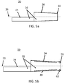
- FIG 5a A sectional view of an exemplary guide device 30 is shown.
- the sectional view is based on an embodiment of the guide device 30 according to FIG Figure 4c , where according to Figure 5a the guide portion 34 has a continuously tapered portion throughout that extends away from the area of the entrance opening 31 .
- the section plane for the section display in Figure 5a corresponds to a plane which is essentially in the height direction R H and conveying direction R F , as in figure 1 shown, opened.
- exemplary embodiments can do without additional cushioning or braking elements.
- Figure 5b 12 shows a sectional view of an exemplary guide device 30 similar to FIG Figure 5a ,
- the guide end section 33 having a contour which is recessed in relation to the guide section 34 .
- the guide device 30 can have a contour that widens radially outwards at the guide end section 33 .
- the set-back leading end section 33 or the radially outwardly widening leading end section 33 enable the arrangement of a braking element 65, such as a rubber ring, in the region of the end section 33.
- a braking element 65 in the area of the end section 33 or in a radial groove, which is formed on an inner peripheral side of the guide device 30 by the end section 33, enables targeted braking of a hollow glass 10 as it slides into the packaging 40, in that the slidably guided hollow glass 10 contacts the braking element 65 at least in sections.
- the one or more sliding surfaces 32 of the guiding device 30 can be provided with one or more cushioning elements 34 .
- Padding elements 34 can be, for example, felts or other materials which prevent scratching of hollow glass 10 during sliding guidance and/or allow a certain sliding friction to be established between hollow glass 10 and guiding device 30 .
- FIG 6 a further embodiment of the packaging system 1 is shown as an example in plan view.
- the hollow glasses 10 are conveyed on a conveyor belt 20 and, following the conveying direction R F , pass through a reorientation device 50 and a sorting device 70, so that after passing through the reorientation device 50 and the sorting device 70, the hollow glasses 10 are arranged next to one another in a transverse direction R Q are.
- the plurality of adjacent hollow glasses 10 can then be exemplified by a corresponding plurality of guide means 30 are slidably guided into the package 40 from a portion of the discharge end 22 of the conveyor belt 20.
- the packaging 40 can be moved counter to the conveying direction RF or counter to the longitudinal direction RL, in order to then slide a further plurality of hollow glasses 10 into the packaging 40 to lead.
- an exemplary embodiment of the packaging system 1 can be equipped with a plurality of guide devices 30 .
- a particularly fast and reliable packaging of hollow glasses 10 is made possible.
Landscapes
- Engineering & Computer Science (AREA)
- Mechanical Engineering (AREA)
- Wrapping Of Specific Fragile Articles (AREA)
- Auxiliary Devices For And Details Of Packaging Control (AREA)
Applications Claiming Priority (1)
| Application Number | Priority Date | Filing Date | Title |
|---|---|---|---|
| DE102020134010.9A DE102020134010B3 (de) | 2020-12-17 | 2020-12-17 | Freies glasverpacken |
Publications (2)
| Publication Number | Publication Date |
|---|---|
| EP4026778A2 true EP4026778A2 (fr) | 2022-07-13 |
| EP4026778A3 EP4026778A3 (fr) | 2022-09-07 |
Family
ID=78918749
Family Applications (1)
| Application Number | Title | Priority Date | Filing Date |
|---|---|---|---|
| EP21215091.6A Withdrawn EP4026778A3 (fr) | 2020-12-17 | 2021-12-16 | Procédé et dispositif pour emballer des verres creux |
Country Status (2)
| Country | Link |
|---|---|
| EP (1) | EP4026778A3 (fr) |
| DE (1) | DE102020134010B3 (fr) |
Cited By (1)
| Publication number | Priority date | Publication date | Assignee | Title |
|---|---|---|---|---|
| CN119460259A (zh) * | 2025-01-15 | 2025-02-18 | 珠海京天世纪科技有限公司 | 一种墨水生产用的包装设备 |
Families Citing this family (2)
| Publication number | Priority date | Publication date | Assignee | Title |
|---|---|---|---|---|
| CN116946472B (zh) * | 2023-07-20 | 2025-08-29 | 昆山真金食品有限公司 | 一种挂耳咖啡的生产方法 |
| CN117302853B (zh) * | 2023-09-19 | 2025-09-12 | 舟山市7412工厂 | 一种零件加工用的多功能导料装置 |
Family Cites Families (10)
| Publication number | Priority date | Publication date | Assignee | Title |
|---|---|---|---|---|
| DE271242C (fr) | ||||
| US1284781A (en) * | 1918-02-11 | 1918-11-12 | Frank M Rogers | Machine for loading bottles into boxes. |
| DE474112C (de) * | 1927-07-17 | 1929-03-27 | Ewald Koerner | Vorrichtung zum Abfuellen von Tabletten und aehnlichen Gegenstaenden |
| US2171650A (en) * | 1938-06-09 | 1939-09-05 | Hack Johann | Machine for mounting bottles in cases |
| US2707042A (en) * | 1953-05-11 | 1955-04-26 | Stanton E Weiler | Merchandise chute |
| GB1353921A (en) * | 1971-02-25 | 1974-05-22 | Cellar Automation Ltd | Apparatus for conveying bottles or like articles |
| SU485037A1 (ru) * | 1974-02-13 | 1975-09-25 | Опытно-Конструкторское И Технологическое Бюро Расфасовочного И Упаковочного Оборудования | Устройство дл укладки штучных изделий |
| SE7507092L (sv) * | 1975-06-19 | 1976-12-20 | Platmanufaktur Ab | Vertikaltransportor |
| US5321929A (en) * | 1992-10-09 | 1994-06-21 | Tomra Systems A/S | Apparatus for positioning articles in boxes or crates |
| EP1606168A1 (fr) | 2003-03-18 | 2005-12-21 | Anker Andersen Retursystem A/S | Dispositif de remplissage de conteneurs avec des objets, tels que des bouteilles en verre |
-
2020
- 2020-12-17 DE DE102020134010.9A patent/DE102020134010B3/de active Active
-
2021
- 2021-12-16 EP EP21215091.6A patent/EP4026778A3/fr not_active Withdrawn
Cited By (1)
| Publication number | Priority date | Publication date | Assignee | Title |
|---|---|---|---|---|
| CN119460259A (zh) * | 2025-01-15 | 2025-02-18 | 珠海京天世纪科技有限公司 | 一种墨水生产用的包装设备 |
Also Published As
| Publication number | Publication date |
|---|---|
| DE102020134010B3 (de) | 2022-06-23 |
| EP4026778A3 (fr) | 2022-09-07 |
Similar Documents
| Publication | Publication Date | Title |
|---|---|---|
| DE602004006164T2 (de) | Zuführsystem für vorformlinge, insbesondere einer behälterblasformmaschine, die mittel zum ausstossen von schlecht positionierten vorformlingen umfasst | |
| DE102020134010B3 (de) | Freies glasverpacken | |
| EP2604411B1 (fr) | Dispositif pour transporter des préformes en plastique | |
| EP3635376B1 (fr) | Dispositif et procédé de vérification de corps creux | |
| EP2509894A1 (fr) | Dispositif pour trier et éliminer des corps cylindriques mal positionnés dans un dispositif de séparation et de transport | |
| AT10979U1 (de) | Sortiervorrichtung | |
| EP2845715A1 (fr) | Unité d'éjecteur et d'inspection | |
| DE202016101207U1 (de) | Transportvorrichtung zum Reihen-weisen Umsetzen von umfallgefährdeten Stückgütern und zur Lagenbildung | |
| WO1999058315A1 (fr) | Procede et dispositif pour produire des corps creux en matiere plastique | |
| EP0472909A1 (fr) | Appareil pour former des rangées et couches de bouteilles | |
| EP2363361A2 (fr) | Dispositif d'empilement et procédé d'empilement de pièces usinées longitudinales | |
| EP2976277A1 (fr) | Procédé et dispositif pour évacuer des récipients d'emballage | |
| WO2024078662A1 (fr) | Dispositif de transport et de séparation de pièces | |
| DE4342084C2 (de) | Vorrrichtung zum Ausrichten von Gegenständen | |
| EP4375046B1 (fr) | Dispositif de transport pour transporter des préformes, installation de moulage par soufflage ainsi que procédé de transport | |
| EP3678792B1 (fr) | Dispositif et procédé de rejet des récipients incorrectement imprimés dans une presse directe | |
| EP3371063B1 (fr) | Dispositif et procédé d'évacuation d'objets dotés d'une surface d'appui ne présentant pas de symétrie de révolution | |
| EP2808275A1 (fr) | Dispositif de convoyage pour récipients et procédé de déviation de récipients d'une première à une seconde direction de transport | |
| DE102014109653A1 (de) | Leerguthandling für Rücknahmesysteme | |
| WO2012139773A2 (fr) | Dispositif et procédé pour déposer des produits en forme de feuille | |
| EP1522509B1 (fr) | Appareil d'empilage de produits plats | |
| EP3571146B1 (fr) | Procédé de tri pour corps creux et dispositif de tri | |
| DE10112566B4 (de) | Zuführung von nachzulegenden Packungen, insbesondere Cigarettenpackungen zu einer Verpackungsmaschine | |
| EP4657071A1 (fr) | Dispositif de prélèvement de nids, système de manipulation de nids et procédé de manipulation d'un nid avec un tub | |
| DE102023119048A1 (de) | Behälterbehandlungsanlage zum Behandeln von Behältern |
Legal Events
| Date | Code | Title | Description |
|---|---|---|---|
| PUAI | Public reference made under article 153(3) epc to a published international application that has entered the european phase |
Free format text: ORIGINAL CODE: 0009012 |
|
| STAA | Information on the status of an ep patent application or granted ep patent |
Free format text: STATUS: THE APPLICATION HAS BEEN PUBLISHED |
|
| AK | Designated contracting states |
Kind code of ref document: A2 Designated state(s): AL AT BE BG CH CY CZ DE DK EE ES FI FR GB GR HR HU IE IS IT LI LT LU LV MC MK MT NL NO PL PT RO RS SE SI SK SM TR |
|
| PUAL | Search report despatched |
Free format text: ORIGINAL CODE: 0009013 |
|
| AK | Designated contracting states |
Kind code of ref document: A3 Designated state(s): AL AT BE BG CH CY CZ DE DK EE ES FI FR GB GR HR HU IE IS IT LI LT LU LV MC MK MT NL NO PL PT RO RS SE SI SK SM TR |
|
| RIC1 | Information provided on ipc code assigned before grant |
Ipc: B65G 47/46 20060101ALI20220802BHEP Ipc: B65G 47/44 20060101ALI20220802BHEP Ipc: B65G 47/252 20060101ALI20220802BHEP Ipc: B65G 11/20 20060101ALI20220802BHEP Ipc: B65G 11/16 20060101ALI20220802BHEP Ipc: B65G 11/12 20060101ALI20220802BHEP Ipc: B65G 11/08 20060101ALI20220802BHEP Ipc: B65G 11/02 20060101ALI20220802BHEP Ipc: B65B 65/00 20060101ALI20220802BHEP Ipc: B65B 59/00 20060101ALI20220802BHEP Ipc: B65B 57/14 20060101ALI20220802BHEP Ipc: B65B 43/56 20060101ALI20220802BHEP Ipc: B65B 39/00 20060101ALI20220802BHEP Ipc: B65B 35/58 20060101ALI20220802BHEP Ipc: B65B 35/24 20060101ALI20220802BHEP Ipc: B07C 5/342 20060101ALI20220802BHEP Ipc: B65B 23/00 20060101ALI20220802BHEP Ipc: B65B 21/10 20060101ALI20220802BHEP Ipc: B65B 5/10 20060101AFI20220802BHEP |
|
| STAA | Information on the status of an ep patent application or granted ep patent |
Free format text: STATUS: THE APPLICATION IS DEEMED TO BE WITHDRAWN |
|
| 18D | Application deemed to be withdrawn |
Effective date: 20230308 |