EP4026958A2 - Dispositif permettant de relier par transfert de force une première partie porteuse de bâtiment à une seconde partie portée de bâtiment - Google Patents
Dispositif permettant de relier par transfert de force une première partie porteuse de bâtiment à une seconde partie portée de bâtiment Download PDFInfo
- Publication number
- EP4026958A2 EP4026958A2 EP22150962.3A EP22150962A EP4026958A2 EP 4026958 A2 EP4026958 A2 EP 4026958A2 EP 22150962 A EP22150962 A EP 22150962A EP 4026958 A2 EP4026958 A2 EP 4026958A2
- Authority
- EP
- European Patent Office
- Prior art keywords
- sleeve
- wall
- building part
- outside
- sleeve wall
- Prior art date
- Legal status (The legal status is an assumption and is not a legal conclusion. Google has not performed a legal analysis and makes no representation as to the accuracy of the status listed.)
- Pending
Links
- 238000004873 anchoring Methods 0.000 claims abstract description 66
- 230000005540 biological transmission Effects 0.000 claims abstract description 31
- 230000003014 reinforcing effect Effects 0.000 claims description 26
- 239000004567 concrete Substances 0.000 claims description 24
- 238000013016 damping Methods 0.000 claims description 19
- 239000000463 material Substances 0.000 claims description 18
- 230000002787 reinforcement Effects 0.000 claims description 6
- 229920001971 elastomer Polymers 0.000 claims description 4
- 239000000806 elastomer Substances 0.000 claims description 4
- 239000004033 plastic Substances 0.000 claims description 4
- 239000000853 adhesive Substances 0.000 claims description 2
- 230000001070 adhesive effect Effects 0.000 claims description 2
- 239000010935 stainless steel Substances 0.000 description 8
- 229910001220 stainless steel Inorganic materials 0.000 description 8
- 229910001294 Reinforcing steel Inorganic materials 0.000 description 6
- 208000002740 Muscle Rigidity Diseases 0.000 description 5
- 238000004519 manufacturing process Methods 0.000 description 5
- 230000015572 biosynthetic process Effects 0.000 description 4
- 238000005260 corrosion Methods 0.000 description 4
- 238000011161 development Methods 0.000 description 4
- 230000018109 developmental process Effects 0.000 description 4
- 238000009415 formwork Methods 0.000 description 4
- 230000000750 progressive effect Effects 0.000 description 4
- 230000007797 corrosion Effects 0.000 description 3
- 230000005484 gravity Effects 0.000 description 3
- 239000007788 liquid Substances 0.000 description 3
- 229910000746 Structural steel Inorganic materials 0.000 description 2
- 238000010521 absorption reaction Methods 0.000 description 2
- 238000010276 construction Methods 0.000 description 2
- 239000002184 metal Substances 0.000 description 2
- 229910001092 metal group alloy Inorganic materials 0.000 description 2
- 230000002093 peripheral effect Effects 0.000 description 2
- 238000010146 3D printing Methods 0.000 description 1
- 229910001209 Low-carbon steel Inorganic materials 0.000 description 1
- 229910000831 Steel Inorganic materials 0.000 description 1
- 238000004026 adhesive bonding Methods 0.000 description 1
- 238000005452 bending Methods 0.000 description 1
- 238000005336 cracking Methods 0.000 description 1
- 230000007613 environmental effect Effects 0.000 description 1
- 238000002347 injection Methods 0.000 description 1
- 239000007924 injection Substances 0.000 description 1
- 238000009434 installation Methods 0.000 description 1
- 238000000034 method Methods 0.000 description 1
- 238000003801 milling Methods 0.000 description 1
- 239000002991 molded plastic Substances 0.000 description 1
- 239000011178 precast concrete Substances 0.000 description 1
- 239000011150 reinforced concrete Substances 0.000 description 1
- 238000007789 sealing Methods 0.000 description 1
- 239000011343 solid material Substances 0.000 description 1
- 239000010959 steel Substances 0.000 description 1
- 238000003466 welding Methods 0.000 description 1
Images




Classifications
-
- E—FIXED CONSTRUCTIONS
- E04—BUILDING
- E04B—GENERAL BUILDING CONSTRUCTIONS; WALLS, e.g. PARTITIONS; ROOFS; FLOORS; CEILINGS; INSULATION OR OTHER PROTECTION OF BUILDINGS
- E04B1/00—Constructions in general; Structures which are not restricted either to walls, e.g. partitions, or floors or ceilings or roofs
- E04B1/38—Connections for building structures in general
- E04B1/48—Dowels, i.e. members adapted to penetrate the surfaces of two parts and to take the shear stresses
- E04B1/483—Shear dowels to be embedded in concrete
-
- E—FIXED CONSTRUCTIONS
- E04—BUILDING
- E04F—FINISHING WORK ON BUILDINGS, e.g. STAIRS, FLOORS
- E04F11/00—Stairways, ramps, or like structures; Balustrades; Handrails
- E04F11/02—Stairways; Layouts thereof
-
- E—FIXED CONSTRUCTIONS
- E04—BUILDING
- E04F—FINISHING WORK ON BUILDINGS, e.g. STAIRS, FLOORS
- E04F11/00—Stairways, ramps, or like structures; Balustrades; Handrails
- E04F11/02—Stairways; Layouts thereof
- E04F2011/0203—Miscellaneous features of stairways not otherwise provided for
- E04F2011/0205—Stairways characterised by the use of specific materials for the supporting structure of the treads
- E04F2011/021—Stairways characterised by the use of specific materials for the supporting structure of the treads mainly of stone or stone like materials, e.g. concrete; mainly of glass
- E04F2011/0212—Stairways characterised by the use of specific materials for the supporting structure of the treads mainly of stone or stone like materials, e.g. concrete; mainly of glass mainly of concrete
Definitions
- the present invention relates to a device for force-transmitting connection of a first supporting building part, in particular a building wall, to a second supporting building part, in particular a stair part.
- This device comprises a sleeve assigned to the second supported building part, which in the installed state, starting from a front edge of the second supported building part facing a joint left between the first and second building part, extends horizontally into the second supported building part and a peripheral sleeve wall, a sleeve base , has an inner region defined by the sleeve wall and the sleeve base and a sleeve opening opposite the sleeve base.
- the sleeve In the installed state of the device, the sleeve extends into the second supported building part in such a way that the sleeve opening is arranged in the area of the front edge and the sleeve base is arranged inside the second supported building part. Furthermore, the device has a support element which, when installed, extends horizontally through the joint between the first building part and the second building part and which, when installed, is partially accommodated in the inner region of the sleeve. Furthermore, this device comprises at least one force transmission element assigned to the second supported building part, which is used to anchor the sleeve in the second supported building part.
- Such a device is, for example, from DE 10 2013 100 356 A1 out.
- Such devices are used in particular wherever forces have to be transmitted between two building parts on the same level, namely above all a weight force acting on the support element from the second supported building part, bending moments acting on the support element and transverse forces.
- These building parts at the same level can be, for example, a stair part and a building wall made of concrete.
- the sleeve When constructing the concrete stair section, the sleeve is integrated into a formwork for the stair section at the desired position before liquid concrete is poured into the formwork. After the liquid concrete has hardened, the sleeve wall and the sleeve base are therefore surrounded by the hardened concrete, so that the carrier element can be partially inserted through the exposed sleeve opening, i.e. not surrounded by concrete, into the inner region of the sleeve and can be stored there.
- the stair part can either be created in the precast concrete plant and then transported to the construction site or created directly on the construction site.
- the support element In the installed state of the device, the support element extends into the first part of the building, in particular into the building wall.
- a joint forms between the building parts when the second supporting building part is connected to the first supporting building part. If the stair section is connected to the building wall, the support element must transfer the weight of the stair section to the building wall, which leads to particularly high loads in the area of the front edge of the supported stair section, i.e. in the area of the stair section adjacent to the joint.
- the force transmission element is provided, which in the device known from the prior art in the installed state starts from a first side of the outer side of the sleeve wall on both sides laterally of the outer side of the sleeve wall into an area on a second side of the outer side of the sleeve wall opposite the first side and thus ensures better anchoring of the carrier element and the sleeve in the stair part.
- the carrier element can be designed either as a mandrel made of solid material or as a hollow profile.
- the device known from the prior art has the disadvantage that in its installed state, with lifting and horizontally acting forces, cracks can form in the material of the second part of the building, in particular the stair part, even below the working load level.
- Such lifting forces arise, for example, through the use of a heavy part of the staircase and/or a geometry of the part of the staircase that is unfavorable for power transmission. They cause the stair part on its side facing away from the building wall downwards, ie tilting in the direction of gravity, while the support element mounted in both the stair part and in the building wall is raised in the building wall upwards, ie against the direction of gravity. In the event of an unfavorable load on the heavy stair section, horizontal forces can also occur.
- a second force transmission element could be provided which, in the installed state, extends from the second side of the outside of the sleeve wall on both sides of the outside of the sleeve wall into an area on the first side of the outside of the sleeve wall, opposite the second side.
- this second force transmission element would have to be arranged as close as possible to the front edge of the second part of the building in order to reduce or completely prevent the formation of cracks in the second part of the building in the event of lifting and/or horizontally acting forces.
- the second force-transmission element would have to consist of stainless steel instead of cheaper reinforcing steel or be covered with an anti-corrosion layer in order to prevent corrosion of this force-transmission element.
- this would uneconomically increase the manufacturing cost of the device.
- the object of the present invention is therefore to provide a device which enables sufficient absorption and transmission of lifting and/or horizontally acting forces in order to thereby reduce crack formation in the material of the second supported building part or even completely avoided, without uneconomically increasing the manufacturing costs of the device.
- the sleeve has at least one first anchoring element protruding in relation to the sleeve for its positive anchoring in the second supported building part on a first side of the outside of the sleeve wall.
- this first anchoring element is surrounded by the material, in particular the hardened concrete, of the second part of the building and thereby anchors the sleeve in the second part of the building.
- the first anchoring element is able to absorb lifting forces acting between the building parts and transmit them to the sleeve and the carrier element.
- cracking in the material of the second part of the building is reduced or even completely avoided.
- This first anchoring element can have a first base body, which in the installed state of the device is essentially oriented in a main bearing direction, and at least one first projection protruding in relation to the first base body.
- This main bearing direction acts mainly against the direction of gravity.
- the first base body and thus the first anchoring element is arranged on an upper outer side of the sleeve wall when the device is installed.
- the sleeve can also have a plurality of first anchoring elements which protrude in relation to the sleeve. For example, a particularly heavy stair section may require the presence of a plurality of first anchoring elements.
- the carrier element can be made of stainless steel, hot-dip galvanized mild steel or the like.
- a further advantageous embodiment of the device according to the invention provides that the sleeve wall has at least one with the first Main body of the first anchoring element has connected wall section with increased wall thickness. This means that this wall section has a greater wall thickness than the remaining sleeve wall.
- This wall section thus represents a continuation of the first anchoring element, which, starting from the first base body, can run partly on the outside of the sleeve wall, in particular partly over a second side of the outside of the shell wall.
- the sleeve wall can also have two wall sections with increased wall thickness connected to the first base body of the first anchoring element, with a first wall section starting from the first base body partially extending over the second side of the outside of the sleeve wall and a second wall section starting from the first base body partially extending over one of the second side opposite third side of the outside of the sleeve wall.
- An advantageous further development of the device according to the invention provides that on the second side of the outside of the sleeve wall at least one second anchoring element is arranged which protrudes in relation to the sleeve wall for positively locking anchoring of the sleeve in the second supported building part, which serves to absorb horizontally acting forces.
- This second anchoring element comprises a second base body and at least one second projection protruding in relation to the second base body, with the second base body being aligned essentially perpendicularly to the main carrying direction when the device is installed.
- the second base body and thus the second anchoring element is arranged on a right-hand or left-hand area of the outside of the sleeve wall when the device is installed.
- the projection of the first and/or second anchoring element enables the respective anchoring element to be interlocked with the material of the second part of the building, in particular the part of the staircase.
- the sleeve wall can have four side walls and a rectangular cross section orthogonal to its longitudinal extent.
- the first base body of the first anchoring element preferably runs perpendicular to the longitudinal extension of the sleeve along a first side wall of the sleeve wall.
- this first side wall is located on the aforementioned first side of the outside of the sleeve wall.
- the second base body of the second anchoring element preferably runs perpendicular to the longitudinal extension of the sleeve along a second side wall of the sleeve wall.
- this second side wall is on the aforementioned second side of the outside of the shell wall.
- the first and the second side wall of the sleeve wall preferably enclose an angle of essentially 90° with respect to one another, which means that the first side wall is oriented essentially perpendicular to the second side wall.
- the previously described first wall section with increased wall thickness, starting from the first base body runs partially over the second side wall of the sleeve wall and the second wall section with increased wall thickness, starting from the first base body, runs partially over a third side wall of the sleeve wall opposite the second side wall, said third side wall being on the aforesaid third side of the outside of the sleeve wall.
- first and/or second anchoring element each have at least one projection which protrudes in relation to the base body of the respective anchoring element, the anchoring of the sleeve in the material of the second part of the building is improved.
- the first and/or the second anchoring element can also have a plurality of projections protruding in relation to the respective base body.
- the first projection and/or the second projection are designed as ribs running essentially perpendicular to the longitudinal extent of the sleeve.
- Such a rib can extend along the entire base body of the respective anchoring element and/or have a wedge shape, the width of which increases in the direction of the sleeve wall of the sleeve. Due to the wedge shape, the interlocking of the respective anchoring element with the material of the second part of the building, in particular the stair part, is improved.
- the force transmission element can be fixed at least indirectly non-positively, frictionally and/or positively on the outside of the sleeve wall, in particular on an area of the first side of the outside of the sleeve wall adjoining the sleeve opening. This is to ensure that the force transmission element activates the areas of the second supported building part that it acts on and can thus transmit the corresponding forces from the support element and the sleeve.
- the force transmission element when the force transmission element is fixed at a distance from the sleeve opening below the required minimum concrete cover, the force transmission element must be made of stainless steel or have corrosion protection. It is therefore advisable to set the force transmission element at a distance from the sleeve opening above the required minimum concrete cover, in order to be able to use a force transmission element made of cheaper reinforcing steel.
- the force transmission element comprises a loop-like middle part that is at least indirectly fixed on the first side of the outside of the sleeve wall and two side parts branching off from the loop-like middle part, the two side parts being essentially parallel to the longitudinal extent of the sleeve in the direction of the sleeve base get lost.
- the wording "at least indirectly” means in this context that the loop-like central part can be fixed either directly or indirectly on the first side of the outside of the sleeve wall. In the former case, the loop-like central part can act on the sleeve directly and thus run along the first side of the outside of the sleeve wall.
- the loop-like middle part and the two side parts arranged on the loop-like middle part can be formed from a one-piece reinforcement bar.
- the loop-like middle part is preferably fixed with the interposition of at least one pressure deflection element and thus indirectly on the first side of the outside of the sleeve wall. Due to its particularly advantageous configuration, this pressure deflection element ensures the possibility of providing an optimal contact between the reinforcing bar and the outside of the sleeve.
- This pressure deflection element must be sufficiently pressure-resistant to transmit the forces directly between the carrier element via the sleeve wall to the pressure deflection element and from there to the reinforcing bar.
- the device comprises at least one pressure deflection element fixed on the first side of the outside of the sleeve wall and two L-shaped force transmission elements connected to the pressure deflection element, each with a first leg and a second leg that is essentially perpendicular to the first leg .
- the first legs each extend out from the first side of the outside of the sleeve wall laterally into an area on the fourth side of the outside of the sleeve wall opposite the first side.
- one of the first legs of the reinforcing rods runs in particular along the second side of the outside of the sleeve wall and/or essentially parallel to the main bearing direction.
- first legs of the reinforcing rods runs in particular along the third side of the outside of the sleeve wall and/or essentially parallel to the main load-bearing direction.
- the second legs each run in the direction of the sleeve base.
- the second limbs can protrude beyond the base of the sleeve and thereby overlap with a reinforcement in the concrete of the second supported building part when the device is installed.
- the first legs of the force transmission elements are non-positively connected to the pressure deflection element, in particular on their side facing away from the second legs. This adhesion can B. be achieved by gluing, welding, latching and / or a headed bolt that leads through a hole in the power transmission element and the pressure element.
- the force-transmitting elements are preferably L-shaped reinforcement rods made of, for example, metal or a metal alloy, in particular reinforcing steel or stainless steel.
- the pressure deflection element can be made of metal or a metal alloy and/or can be made semi-elliptical, in particular semi-circular.
- the device has a further advantageous embodiment Stress damping element, which at least partially runs around the outside of the sleeve wall and is preferably made of a material with reduced rigidity compared to concrete, in particular made of an elastomer.
- the stress-damping element can be arranged between the latching means and the sleeve opening or between the latching means and the front edge of the second building part on the outside of the sleeve wall.
- the force transmission element and/or the first anchoring element is arranged at a distance from the sleeve opening on the outside of the sleeve wall.
- This spacing of the force transmission element from the sleeve opening or the front edge of the second building part means that structural steel or reinforcing steel can now be used as the material for the force transmission element instead of stainless steel, which is more susceptible to corrosion, but due to the distance caused by the stress damping element from the joint and the associated compliance with the required minimum concrete cover is sufficient.
- the use of the very expensive stainless steel which makes the system unattractive, can be avoided.
- the pressure deflection element By using a material with reduced stiffness compared to concrete for the stress-damping element, the forces acting on the front edge of the supported building part are not passed on 1:1 to the overlying material of the second building part, but to a reduced, ie buffered, extent.
- the sleeve has on the outside of the wall a collar surrounding the sleeve opening, which collar can be used, for example, to fix the sleeve to a component formwork during the production of the second supported building part, so that when the material of the second part of the building the sleeve remains in the correct position.
- the sleeve wall, the sleeve base, the first and/or second anchoring element, the latching means and/or the collar can be made in one piece from plastic, in particular injection-moulded, 3D-printed or milled plastic, which significantly simplifies the manufacture of the device.
- the sleeve can be an injection molded part.
- the sleeve can also be produced using a 3D printing process or by milling.
- FIG 1 Figure 12 shows an example of application of a first embodiment of a device 1 according to the invention, which is arranged in a second supporting building part 2 and is intended to extend into a first supporting building part 3.
- the first supporting building part 3 is a vertically oriented building wall and the second supporting building part 2 is a stair part. Both the building wall 3 and the stair part 2 are made of steel-reinforced concrete. As an alternative to this, the building wall 3 can also be made of masonry.
- the building wall 3 is in the figure 1 only indicated with the reference number 3.
- the device 1 is used for force-transmitting connection of the stair part 2 with the building wall 3.
- figure 2 shows the first exemplary embodiment of the device 1 according to the invention figure 1 in its installed state between the stair part 2 and the building wall 3.
- a joint 4 is formed, for example, with an additional, in the figure 2 fire protection element not shown can be filled.
- the device 1 comprises a sleeve 5 assigned to the stair part 2, which extends horizontally into the stair part 2, starting from a front edge 21 of the stair part 2 facing the joint left between the building wall 3 and the stair part 2, and a peripheral sleeve wall 6, a sleeve base 7 and has a sleeve opening 8 opposite the sleeve base 7 .
- this sleeve 5 is made of injection-molded plastic and has a rectangular cross-section orthogonally to its longitudinal extent. Furthermore, the device 1 has a carrier element 9 which extends in the horizontal direction through the joint 4 between the building wall 3 and the stair part 2 and which is partially integrated into a figure 2 not shown inner region 10 of the sleeve 5 is added and at the same time extends over the joint 4 in the building wall 3 in the horizontal direction.
- this carrier element 9 is designed as a hollow profile made of hot-dip galvanized structural steel.
- the second leg 112 of the first reinforcing bar 11 runs on the fourth side 612 of the outside 61 of the sleeve wall 6 in the direction of the sleeve base 7 and parallel to the longitudinal extension of the sleeve 5.
- the second leg is positioned 112 of the first reinforcing bar 11 protrudes over the sleeve base 7 and can therefore, when the device 1 is installed, have an in figure 2 not shown reinforcement in the concrete of the stair part 2 overlap.
- the device 1 also includes a pressure deflection element 12 fixed on the first side 611 of the outside 61 of the sleeve wall 6 and made of steel.
- the first leg 111 of the first reinforcing bar 11 is non-positively connected to the pressure deflection element 12 on its side facing away from the second leg 112 .
- the sleeve wall 6 On its outer side 61, the sleeve wall 6 has a latching means 13 for positively locking the pressure deflection element 12 on the first side 611 of the outer side 61 of the sleeve wall 6, which comprises two latching lugs 131, 132 facing one another.
- the pressure deflection element 12 is clipped into these latching lugs 131 , 132 .
- the sleeve 5 comprises on the first side 611 of the outside 61 of the sleeve wall 6 a first anchoring element 14 protruding in relation to the sleeve 5 with a first base body 141, which is aligned in a main load-bearing direction, and four in relation to the first Base body 141 projecting projections 142, 143, 144, 145.
- the projections 142, 143, 144, 145 of the first anchoring element 14 are formed as perpendicular to the longitudinal extent of the sleeve extending ribs having a wedge shape, the width of which in the direction of the sleeve wall 6 increases.
- the projections 142, 143, 144, 145 of the first anchoring element 14 designed as ribs extend along the entire width of the first base body 141.
- the first anchoring element 14 is surrounded by the hardened concrete of the stair part 2 and thereby anchors the sleeve 5 in the stair part.
- the first anchoring element 14 is able to absorb lifting forces acting between the building parts 2 , 3 and to transmit them to the sleeve 5 and the carrier element 9 . This avoids the formation of cracks in the concrete of the stair part.
- one of the projections 142 is arranged on a side of the first anchoring element 14 that faces the pressure deflection element 12 .
- One of the latching lugs 132 of the latching means 13 is also arranged on the side of the first anchoring element 14 facing the pressure deflection element 12 .
- Out of figure 2 also shows that the sleeve wall 6 has a first wall section 15 with an increased wall thickness connected to the first base body 141 of the first anchoring element 14 .
- This first wall section 15 has a greater wall thickness than the remaining sleeve wall 6 and represents a continuation of the first anchoring element 14. Starting from the first base body 141, this first wall section 15 runs partially over the third side 613 of the outside 61 of the sleeve wall 6.
- the third side 613 is aligned essentially perpendicular to the first side 611 of the outside 61 of the sleeve wall 6 .
- the sleeve wall 6 also includes a second, in figure 2 wall section 17 with increased wall thickness, which cannot be seen and which is connected to the first base body 141 of the first anchoring element 14, which, starting from the first base body 141, runs partially over a second side 614 of the outside 61 of the sleeve wall 6, opposite the third side 613.
- the second side 614 is aligned essentially perpendicular to the first side 611 of the outside 61 of the sleeve wall 6 .
- the device 1 also has a stress-damping element 16 which runs all the way around the outer side 61 of the sleeve wall 6 and is made of an elastomer.
- This stress-damping element 16 is arranged between the latching means 13 and the sleeve opening 8 or between the latching means 13 and the front edge 21 of the step part 2 on the outside 61 of the sleeve wall 6 .
- the rebar 11 and the first Anchoring element 14 is arranged on the outside 61 of the sleeve wall 6 at a distance from the sleeve opening 8 .
- This spacing of the reinforcing bar 11 from the sleeve opening 8 or the front edge 21 of the step part 2 means that reinforcing steel can be used as the material for the reinforcing bar 11 instead of stainless steel of joint 4 and the associated compliance with the required minimum concrete cover is sufficient. As a result, the use of the very expensive stainless steel, which makes the system unattractive, can be avoided.
- the stress-damping element 16 By using elastomers for the stress-damping element 16, the forces acting on the front edge 21 of the stair part 2 are not passed on 1:1 to the overlying concrete of the stair part 2, but to a reduced, ie buffered, extent. This results in a slowly increasing, progressive rigidity, in that at the beginning, i.e.
- the sleeve 5 is mounted comparatively softly with the carrier element 9 and can give way somewhat in the direction of the stress-damping element 16 and then along its longitudinal extension into the stair part becomes more and more rigid in the course of the binding length.
- the consequence of the progressive rigidity is that at the front edge 21 of the stair part 2 above the sleeve 5 the concrete of the stair part can no longer flake off.
- figure 3 shows a first detail of the first exemplary embodiment from FIGS figures 1 and 2 , namely the sleeve 5 with the two L-shaped force transmission elements 11, 18 in the form of reinforcing bars and the stress-damping element 16 in a perspective view from the front.
- the device 1 has two reinforcing rods 11, 18.
- the second rebar 18 also comprises a first leg 181 and a second leg 182 that is essentially perpendicular to the first leg 181, with the first leg 181 of the rebar 11 starting from the first side 611 of the outer side 61 of the
- the sleeve wall 6 extends laterally into the area of the fourth side 612 of the outside 61 of the sleeve wall 6 and runs along a fourth side 614 of the outside 61 of the sleeve wall 6 .
- the second leg 182 of the second reinforcing bar 18 runs on the fourth side 612 of the outside 61 of the sleeve wall 6 in the direction of the sleeve base 7 and parallel to the longitudinal extent of the sleeve 5.
- the second leg 182 of the second reinforcing bar 18 also projects beyond the sleeve base 7.
- the first leg 181 of the second reinforcing bar 18 is non-positively connected to the pressure deflection element 12 on its side facing away from the second leg 182 .
- the reinforcing rods 11, 18 run to the right and left of the outer side 61 of the sleeve wall 6 of the sleeve 5
- figure 3 shows that the device has a second locking means 19 with two mutually facing locking lugs 191, 192, wherein in figure 3 only one of the two detents 191, 192 can be seen.
- This second latching means 19 is arranged between the first latching means 13 and the sleeve opening 8 on the first side 611 of the outside 61 of the sleeve wall 6 .
- the stress-damping element 16 is clipped in between the two latching lugs 191 , 192 of the second latching means 19 .
- the second latching means 19 is therefore only used for the positive fixing of the stress-damping element 16 on the outside 18 of the sleeve wall 6.
- figure 4 shows a second detail of the first exemplary embodiment from FIGS figures 1 and 2 , namely the sleeve 5 in a perspective view from the front.
- the sleeve opening 8 and the inner region 10 of the sleeve 5 defined by the sleeve wall 6 and the sleeve bottom 7 can be seen.
- the outer side 61 of the sleeve wall 6 has a surface profiling 62 which serves to stiffen the sleeve wall 6 .
- the sleeve 5 On the outside 61 of the sleeve wall 6, the sleeve 5 has a collar 20 surrounding the sleeve opening 8, which can be used, for example, to fix the sleeve 5 to a component formwork during the manufacture of the stair part 2, so that during the pouring and subsequent hardening of the liquid concrete of the Stair part 2, the sleeve 5 remains in the correct position.
- figure 5 shows a third detail of the first exemplary embodiment from FIGS figures 1 and 2 , namely the sleeve 5 in a perspective view from behind. From this figure 5 shows that on the outer side 61 of the sleeve wall 6 there is a second anchoring element 21 which protrudes in relation to the sleeve wall 6 and which serves to positively anchor the sleeve 5 in the stair part 2 and to absorb horizontally acting forces.
- This second anchoring element 21 has a second base body 211 and a second projection 212 protruding in relation to the second base body 211 .
- the second base body 211 is aligned perpendicular to the main bearing direction on the second side 614 of the outside 61 of the sleeve wall 6 .
- the second projection 212 is designed as a rib running perpendicularly to the longitudinal extension of the sleeve, which has a wedge shape, the width of which increases in the direction of the sleeve wall 6 .
- the second projection 212, designed as a rib, of the second anchoring element 21 extends only partially along the width of the second base body 211.
- figure 6 shows a fourth detail of the first exemplary embodiment from FIGS figures 1 and 2 , namely the pressure deflection element 12 and the two L-shaped force transmission elements 11, 18 in the form of reinforcing bars.
- the first legs 111, 181 are non-positively connected to the pressure deflection element 12 on their side facing away from the second legs 112, 182.
- the reinforcing rods 11, 18 are bent or angled in such a way that the first legs 111, 181 are perpendicular to the second legs 112, 182.
- the pressure deflection element 12 is approximately semi-elliptical.
- the device 1 has a force transmission element 22 in the form of a reinforcing rod.
- figure 7 shows a detail of this second embodiment, namely such a rebar 22.
- This rebar 22 includes a loop-like, fixed on the first side 611 of the outside 61 of the sleeve wall 6 middle part 221 and two of the loop-like middle part 221 branching side parts 222, 223, wherein the two Side parts 222, 223 run essentially parallel to the longitudinal extension of the sleeve 5 in the direction of the sleeve base 7.
- the loop-like central part 221 is designed in such a way that it can be fixed on the first side 611 of the outside 61 of the sleeve wall 6 of a sleeve 5, the sleeve wall 6 of which has a circular cross section orthogonal to its longitudinal extent.
- the device 1 has a force transmission element 23 in the form of a reinforcing rod and a pressure deflection element 24 which is approximately semicircular.
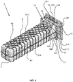
- figure 8 shows a detail of this third embodiment, namely the reinforcing bar 23 and the pressure deflection element 24.
- the reinforcing bar 23 has the same features as in FIG figure 7 shown rebar 22 on.
- the loop-like middle part 231 can be fixed on the first side 611 of the outside 61 of the sleeve wall 6 with the pressure deflection element 24 interposed, the loop-like middle part 231 being connected to the pressure deflection element 24 in a non-positive manner.
- figure 9 shows a further reinforcement bar 25 for a fourth exemplary embodiment of the device 1 in detail, which differs from that in figure 7 shown rebar 22 differs in that its loop-like middle part 251 can be fixed on the first side 611 of the outside 61 of the sleeve wall 6 of a sleeve 5, the sleeve wall 6 of which has a rectangular cross-section orthogonal to its longitudinal extent.
- the device 1 has a force transmission element 26 in the form of a reinforcing rod and two pressure deflection elements 27, 28, each of which is approximately semicircular.
- figure 10 shows a detail of this fifth embodiment, namely the reinforcing bar 26 and the pressure deflection elements 27, 28.
- the reinforcing bar 26 has the same characteristics as in figure 9 shown rebar 25 on.
- the loop-like middle part 261 can be fixed on the first side 611 of the outside 61 of the sleeve wall 6 with the pressure deflection elements 27, 28 interposed, the loop-like middle part 261 being non-positively connected to the pressure deflection elements 27, 28.
Landscapes
- Engineering & Computer Science (AREA)
- Architecture (AREA)
- Physics & Mathematics (AREA)
- Electromagnetism (AREA)
- Civil Engineering (AREA)
- Structural Engineering (AREA)
- Joining Of Building Structures In Genera (AREA)
- Steps, Ramps, And Handrails (AREA)
- Mutual Connection Of Rods And Tubes (AREA)
Applications Claiming Priority (1)
| Application Number | Priority Date | Filing Date | Title |
|---|---|---|---|
| DE102021100348.2A DE102021100348A1 (de) | 2021-01-12 | 2021-01-12 | Vorrichtung zum kraftübertragenden Verbinden eines ersten tragenden Gebäudeteils mit einem zweiten getragenen Gebäudeteil |
Publications (2)
| Publication Number | Publication Date |
|---|---|
| EP4026958A2 true EP4026958A2 (fr) | 2022-07-13 |
| EP4026958A3 EP4026958A3 (fr) | 2022-10-12 |
Family
ID=79317111
Family Applications (1)
| Application Number | Title | Priority Date | Filing Date |
|---|---|---|---|
| EP22150962.3A Pending EP4026958A3 (fr) | 2021-01-12 | 2022-01-11 | Dispositif permettant de relier par transfert de force une première partie porteuse de bâtiment à une seconde partie portée de bâtiment |
Country Status (2)
| Country | Link |
|---|---|
| EP (1) | EP4026958A3 (fr) |
| DE (1) | DE102021100348A1 (fr) |
Families Citing this family (2)
| Publication number | Priority date | Publication date | Assignee | Title |
|---|---|---|---|---|
| DE102023118880A1 (de) | 2023-07-17 | 2025-01-23 | Schöck Bauteile GmbH | Modul zum Befüllen eines Einbauelementes, Einbauelement für ein Fertigteilelement, Fertigteilelement aus Beton und Verfahren zur Herstellung eines Fertigteilelementes |
| DE102023135849A1 (de) * | 2023-12-19 | 2025-06-26 | Schöck Bauteile GmbH | Vorrichtung zum Verbinden von Gebäudeteilen, Gebäudeabschnitt und Verfahren zum Verbinden von Gebäudeteilen |
Citations (2)
| Publication number | Priority date | Publication date | Assignee | Title |
|---|---|---|---|---|
| DE102013100356A1 (de) | 2013-01-14 | 2014-07-17 | Schöck Bauteile GmbH | Vorrichtung zum kraftübertragenden Verbinden eines ersten tragenden Gebäudeteils mit einem zweiten getragenen Gebäudeteil |
| EP3460134A1 (fr) * | 2017-09-20 | 2019-03-27 | Alfred Redlberger | Dispositif de raccordement par transmission de force entre deux éléments constructifs |
Family Cites Families (7)
| Publication number | Priority date | Publication date | Assignee | Title |
|---|---|---|---|---|
| DE3408556A1 (de) | 1984-03-08 | 1985-09-12 | Eberhard Ing.(grad.) 7570 Baden-Baden Schöck | Trennelement fuer betonplatten |
| DE19700765A1 (de) | 1997-01-11 | 1998-07-16 | Elasto Gleitlager Technik Gmbh | Querkraftdornlager |
| NO321443B1 (no) * | 2004-06-30 | 2006-05-08 | Sb Produksjon As | Sammenforingssystem, enkeltelementer og fremgangsmate for bruk av dette |
| NO333354B1 (no) * | 2010-12-21 | 2013-05-13 | Svein Berg Holding As | Anordning ved et sammenforingssystem for bygningselementer. |
| US20200056369A1 (en) * | 2016-10-20 | 2020-02-20 | Srg Ip Pty Ltd | Improved Connector for Use in Forming Joints |
| DE102017002916A1 (de) | 2017-03-23 | 2018-09-27 | Harald Roßberger | Dreidimensionale Elemente |
| FI130872B1 (fi) * | 2018-05-31 | 2024-04-30 | Flow Modules Oy | Järjestely ja kiinnitysmenetelmä elementin kiinnityksen toteuttamiseksi ontelolaattaan |
-
2021
- 2021-01-12 DE DE102021100348.2A patent/DE102021100348A1/de active Pending
-
2022
- 2022-01-11 EP EP22150962.3A patent/EP4026958A3/fr active Pending
Patent Citations (2)
| Publication number | Priority date | Publication date | Assignee | Title |
|---|---|---|---|---|
| DE102013100356A1 (de) | 2013-01-14 | 2014-07-17 | Schöck Bauteile GmbH | Vorrichtung zum kraftübertragenden Verbinden eines ersten tragenden Gebäudeteils mit einem zweiten getragenen Gebäudeteil |
| EP3460134A1 (fr) * | 2017-09-20 | 2019-03-27 | Alfred Redlberger | Dispositif de raccordement par transmission de force entre deux éléments constructifs |
Also Published As
| Publication number | Publication date |
|---|---|
| DE102021100348A1 (de) | 2022-07-14 |
| EP4026958A3 (fr) | 2022-10-12 |
Similar Documents
| Publication | Publication Date | Title |
|---|---|---|
| EP2644776A1 (fr) | Paroi de protection et élément de paroi de protection destiné à la fabrication de celle-ci | |
| EP2486196B1 (fr) | Procédé et dispositif pour l'ajout postérieur d'une partie extérieure en saillie à une partie de bâtiment existante | |
| DE102011088456B4 (de) | Anordnung mit Positionierungselement zum Positionieren zumindest eines stabförmigen Bewehrungselementes | |
| DE102021100348A1 (de) | Vorrichtung zum kraftübertragenden Verbinden eines ersten tragenden Gebäudeteils mit einem zweiten getragenen Gebäudeteil | |
| EP2459813B1 (fr) | Élément de béton armé à armature formée d'éléments de tôle en l | |
| EP2754766B1 (fr) | Dispositif permettant de relier, avec transmission de forces, une première partie porteuse d'un bâtiment à une seconde partie portée du bâtiment | |
| DE202018003027U1 (de) | Verbindungsstück zur winkeligen Verbindung zweier Bauteile | |
| DE202011110605U1 (de) | Schalungsanordnung | |
| DE102016106036A1 (de) | Anschlussbauteil zur Wärmeentkopplung zwischen einem vertikalen und einem horizontalen Gebäudeteil | |
| EP0959188B1 (fr) | Element de plaque et/ou de joint en porte-à-faux pour constructions en béton armé | |
| DE29917220U1 (de) | Montageträgersystem mit Einbauhilfe | |
| DE10014977A1 (de) | Profilschiene | |
| EP3839162B1 (fr) | Composant thermo-isolant destiné à être utilisé dans une fente de séparation entre deux parties de construction | |
| DE202017107261U1 (de) | Betonfertigteil mit mindestens einem eine Last aufnehmenden Bauteil | |
| DE102004040584A1 (de) | Bauelement zur Schubbewehrung | |
| EP1887155B1 (fr) | Elément d'isolation thermique | |
| DE102011056105B4 (de) | Montagezusatzelement für die Befestigung von Bauelementen, z.B. Kellerlichtschächten an Gebäudewänden | |
| EP3835501B1 (fr) | Arrangement pour connecter une pièce de construction avec une partie extérieure frontale | |
| EP2379824B1 (fr) | Ancre de fixation destinée à la fixation d'une façade | |
| DE102011056967A1 (de) | Plattenanschlusselement | |
| DE102004003366B4 (de) | Verfahren zum Herstellen eines Einfamilien-oder Mehrfamilienhauses, Betonfertigteil-Trogplatte für eine Gebäudedecke sowie Fertighaus | |
| EP2276898A1 (fr) | Pièce de montage préfabriquée possédant un dispositif de stabilisation | |
| EP4299861A1 (fr) | Dispositif et procédé de renforcement ultérieur d'un composant doté d'au moins une zone de discontinuité | |
| EP4339383A1 (fr) | Dispositif de liaison pour la liaison de transmission de force d'une première partie de construction absorbant de force à une seconde partie de construction absorbant de force et construction | |
| DE10060527B4 (de) | Querkraft-Verbindung im Fertigteilbau |
Legal Events
| Date | Code | Title | Description |
|---|---|---|---|
| PUAI | Public reference made under article 153(3) epc to a published international application that has entered the european phase |
Free format text: ORIGINAL CODE: 0009012 |
|
| STAA | Information on the status of an ep patent application or granted ep patent |
Free format text: STATUS: THE APPLICATION HAS BEEN PUBLISHED |
|
| AK | Designated contracting states |
Kind code of ref document: A2 Designated state(s): AL AT BE BG CH CY CZ DE DK EE ES FI FR GB GR HR HU IE IS IT LI LT LU LV MC MK MT NL NO PL PT RO RS SE SI SK SM TR |
|
| PUAL | Search report despatched |
Free format text: ORIGINAL CODE: 0009013 |
|
| AK | Designated contracting states |
Kind code of ref document: A3 Designated state(s): AL AT BE BG CH CY CZ DE DK EE ES FI FR GB GR HR HU IE IS IT LI LT LU LV MC MK MT NL NO PL PT RO RS SE SI SK SM TR |
|
| RIC1 | Information provided on ipc code assigned before grant |
Ipc: E04B 1/48 20060101AFI20220907BHEP |
|
| STAA | Information on the status of an ep patent application or granted ep patent |
Free format text: STATUS: REQUEST FOR EXAMINATION WAS MADE |
|
| 17P | Request for examination filed |
Effective date: 20230321 |
|
| RBV | Designated contracting states (corrected) |
Designated state(s): AL AT BE BG CH CY CZ DE DK EE ES FI FR GB GR HR HU IE IS IT LI LT LU LV MC MK MT NL NO PL PT RO RS SE SI SK SM TR |
|
| STAA | Information on the status of an ep patent application or granted ep patent |
Free format text: STATUS: EXAMINATION IS IN PROGRESS |
|
| 17Q | First examination report despatched |
Effective date: 20250123 |