EP4026986A2 - Fixation de surface portante pour rotor d'éolienne - Google Patents
Fixation de surface portante pour rotor d'éolienne Download PDFInfo
- Publication number
- EP4026986A2 EP4026986A2 EP22151234.6A EP22151234A EP4026986A2 EP 4026986 A2 EP4026986 A2 EP 4026986A2 EP 22151234 A EP22151234 A EP 22151234A EP 4026986 A2 EP4026986 A2 EP 4026986A2
- Authority
- EP
- European Patent Office
- Prior art keywords
- turbine
- disk
- turbine blades
- rows
- equal
- Prior art date
- Legal status (The legal status is an assumption and is not a legal conclusion. Google has not performed a legal analysis and makes no representation as to the accuracy of the status listed.)
- Pending
Links
- 239000011153 ceramic matrix composite Substances 0.000 claims description 20
- 239000000463 material Substances 0.000 claims description 16
- 239000007789 gas Substances 0.000 description 18
- 229910010293 ceramic material Inorganic materials 0.000 description 7
- 238000007789 sealing Methods 0.000 description 7
- 239000000919 ceramic Substances 0.000 description 6
- 239000000835 fiber Substances 0.000 description 6
- 230000008901 benefit Effects 0.000 description 5
- 239000000446 fuel Substances 0.000 description 5
- 238000000034 method Methods 0.000 description 5
- 230000009467 reduction Effects 0.000 description 5
- PXHVJJICTQNCMI-UHFFFAOYSA-N Nickel Chemical compound [Ni] PXHVJJICTQNCMI-UHFFFAOYSA-N 0.000 description 4
- 239000007769 metal material Substances 0.000 description 4
- 230000000712 assembly Effects 0.000 description 3
- 238000000429 assembly Methods 0.000 description 3
- 230000008859 change Effects 0.000 description 3
- 238000010276 construction Methods 0.000 description 3
- HBMJWWWQQXIZIP-UHFFFAOYSA-N silicon carbide Chemical class [Si+]#[C-] HBMJWWWQQXIZIP-UHFFFAOYSA-N 0.000 description 3
- 230000003068 static effect Effects 0.000 description 3
- 239000000956 alloy Substances 0.000 description 2
- 238000002485 combustion reaction Methods 0.000 description 2
- 239000004744 fabric Substances 0.000 description 2
- 229910052759 nickel Inorganic materials 0.000 description 2
- 230000003071 parasitic effect Effects 0.000 description 2
- 229910010271 silicon carbide Inorganic materials 0.000 description 2
- 238000009987 spinning Methods 0.000 description 2
- OKTJSMMVPCPJKN-UHFFFAOYSA-N Carbon Chemical compound [C] OKTJSMMVPCPJKN-UHFFFAOYSA-N 0.000 description 1
- 229910045601 alloy Inorganic materials 0.000 description 1
- 239000004760 aramid Substances 0.000 description 1
- 229920003235 aromatic polyamide Polymers 0.000 description 1
- 229910052799 carbon Inorganic materials 0.000 description 1
- 229910017052 cobalt Inorganic materials 0.000 description 1
- 239000010941 cobalt Substances 0.000 description 1
- GUTLYIVDDKVIGB-UHFFFAOYSA-N cobalt atom Chemical compound [Co] GUTLYIVDDKVIGB-UHFFFAOYSA-N 0.000 description 1
- 238000004891 communication Methods 0.000 description 1
- 230000000295 complement effect Effects 0.000 description 1
- 230000006835 compression Effects 0.000 description 1
- 238000007906 compression Methods 0.000 description 1
- 238000012937 correction Methods 0.000 description 1
- 238000013461 design Methods 0.000 description 1
- 239000002657 fibrous material Substances 0.000 description 1
- 238000010348 incorporation Methods 0.000 description 1
- 239000011159 matrix material Substances 0.000 description 1
- 230000007246 mechanism Effects 0.000 description 1
- 239000002184 metal Substances 0.000 description 1
- 229910052751 metal Inorganic materials 0.000 description 1
- 150000002739 metals Chemical class 0.000 description 1
- 239000000203 mixture Substances 0.000 description 1
- 238000012986 modification Methods 0.000 description 1
- 230000004048 modification Effects 0.000 description 1
- 230000004044 response Effects 0.000 description 1
- 229910000601 superalloy Inorganic materials 0.000 description 1
Images


Classifications
-
- F—MECHANICAL ENGINEERING; LIGHTING; HEATING; WEAPONS; BLASTING
- F01—MACHINES OR ENGINES IN GENERAL; ENGINE PLANTS IN GENERAL; STEAM ENGINES
- F01D—NON-POSITIVE DISPLACEMENT MACHINES OR ENGINES, e.g. STEAM TURBINES
- F01D5/00—Blades; Blade-carrying members; Heating, heat-insulating, cooling or antivibration means on the blades or the members
- F01D5/30—Fixing blades to rotors; Blade roots ; Blade spacers
- F01D5/3007—Fixing blades to rotors; Blade roots ; Blade spacers of axial insertion type
-
- F—MECHANICAL ENGINEERING; LIGHTING; HEATING; WEAPONS; BLASTING
- F01—MACHINES OR ENGINES IN GENERAL; ENGINE PLANTS IN GENERAL; STEAM ENGINES
- F01D—NON-POSITIVE DISPLACEMENT MACHINES OR ENGINES, e.g. STEAM TURBINES
- F01D5/00—Blades; Blade-carrying members; Heating, heat-insulating, cooling or antivibration means on the blades or the members
- F01D5/02—Blade-carrying members, e.g. rotors
-
- F—MECHANICAL ENGINEERING; LIGHTING; HEATING; WEAPONS; BLASTING
- F02—COMBUSTION ENGINES; HOT-GAS OR COMBUSTION-PRODUCT ENGINE PLANTS
- F02C—GAS-TURBINE PLANTS; AIR INTAKES FOR JET-PROPULSION PLANTS; CONTROLLING FUEL SUPPLY IN AIR-BREATHING JET-PROPULSION PLANTS
- F02C7/00—Features, components parts, details or accessories, not provided for in, or of interest apart form groups F02C1/00 - F02C6/00; Air intakes for jet-propulsion plants
- F02C7/36—Power transmission arrangements between the different shafts of the gas turbine plant, or between the gas-turbine plant and the power user
-
- F—MECHANICAL ENGINEERING; LIGHTING; HEATING; WEAPONS; BLASTING
- F01—MACHINES OR ENGINES IN GENERAL; ENGINE PLANTS IN GENERAL; STEAM ENGINES
- F01D—NON-POSITIVE DISPLACEMENT MACHINES OR ENGINES, e.g. STEAM TURBINES
- F01D5/00—Blades; Blade-carrying members; Heating, heat-insulating, cooling or antivibration means on the blades or the members
- F01D5/12—Blades
- F01D5/28—Selecting particular materials; Particular measures relating thereto; Measures against erosion or corrosion
- F01D5/282—Selecting composite materials, e.g. blades with reinforcing filaments
-
- F—MECHANICAL ENGINEERING; LIGHTING; HEATING; WEAPONS; BLASTING
- F01—MACHINES OR ENGINES IN GENERAL; ENGINE PLANTS IN GENERAL; STEAM ENGINES
- F01D—NON-POSITIVE DISPLACEMENT MACHINES OR ENGINES, e.g. STEAM TURBINES
- F01D5/00—Blades; Blade-carrying members; Heating, heat-insulating, cooling or antivibration means on the blades or the members
- F01D5/12—Blades
- F01D5/28—Selecting particular materials; Particular measures relating thereto; Measures against erosion or corrosion
- F01D5/284—Selection of ceramic materials
-
- F—MECHANICAL ENGINEERING; LIGHTING; HEATING; WEAPONS; BLASTING
- F01—MACHINES OR ENGINES IN GENERAL; ENGINE PLANTS IN GENERAL; STEAM ENGINES
- F01D—NON-POSITIVE DISPLACEMENT MACHINES OR ENGINES, e.g. STEAM TURBINES
- F01D5/00—Blades; Blade-carrying members; Heating, heat-insulating, cooling or antivibration means on the blades or the members
- F01D5/30—Fixing blades to rotors; Blade roots ; Blade spacers
- F01D5/3084—Fixing blades to rotors; Blade roots ; Blade spacers the blades being made of ceramics
-
- F—MECHANICAL ENGINEERING; LIGHTING; HEATING; WEAPONS; BLASTING
- F05—INDEXING SCHEMES RELATING TO ENGINES OR PUMPS IN VARIOUS SUBCLASSES OF CLASSES F01-F04
- F05D—INDEXING SCHEME FOR ASPECTS RELATING TO NON-POSITIVE-DISPLACEMENT MACHINES OR ENGINES, GAS-TURBINES OR JET-PROPULSION PLANTS
- F05D2220/00—Application
- F05D2220/30—Application in turbines
- F05D2220/32—Application in turbines in gas turbines
- F05D2220/321—Application in turbines in gas turbines for a special turbine stage
- F05D2220/3215—Application in turbines in gas turbines for a special turbine stage the last stage of the turbine
-
- F—MECHANICAL ENGINEERING; LIGHTING; HEATING; WEAPONS; BLASTING
- F05—INDEXING SCHEMES RELATING TO ENGINES OR PUMPS IN VARIOUS SUBCLASSES OF CLASSES F01-F04
- F05D—INDEXING SCHEME FOR ASPECTS RELATING TO NON-POSITIVE-DISPLACEMENT MACHINES OR ENGINES, GAS-TURBINES OR JET-PROPULSION PLANTS
- F05D2240/00—Components
- F05D2240/20—Rotors
- F05D2240/24—Rotors for turbines
-
- F—MECHANICAL ENGINEERING; LIGHTING; HEATING; WEAPONS; BLASTING
- F05—INDEXING SCHEMES RELATING TO ENGINES OR PUMPS IN VARIOUS SUBCLASSES OF CLASSES F01-F04
- F05D—INDEXING SCHEME FOR ASPECTS RELATING TO NON-POSITIVE-DISPLACEMENT MACHINES OR ENGINES, GAS-TURBINES OR JET-PROPULSION PLANTS
- F05D2260/00—Function
- F05D2260/40—Transmission of power
- F05D2260/403—Transmission of power through the shape of the drive components
- F05D2260/4031—Transmission of power through the shape of the drive components as in toothed gearing
- F05D2260/40311—Transmission of power through the shape of the drive components as in toothed gearing of the epicyclical, planetary or differential type
-
- F—MECHANICAL ENGINEERING; LIGHTING; HEATING; WEAPONS; BLASTING
- F05—INDEXING SCHEMES RELATING TO ENGINES OR PUMPS IN VARIOUS SUBCLASSES OF CLASSES F01-F04
- F05D—INDEXING SCHEME FOR ASPECTS RELATING TO NON-POSITIVE-DISPLACEMENT MACHINES OR ENGINES, GAS-TURBINES OR JET-PROPULSION PLANTS
- F05D2300/00—Materials; Properties thereof
- F05D2300/60—Properties or characteristics given to material by treatment or manufacturing
- F05D2300/603—Composites; e.g. fibre-reinforced
- F05D2300/6033—Ceramic matrix composites [CMC]
-
- Y—GENERAL TAGGING OF NEW TECHNOLOGICAL DEVELOPMENTS; GENERAL TAGGING OF CROSS-SECTIONAL TECHNOLOGIES SPANNING OVER SEVERAL SECTIONS OF THE IPC; TECHNICAL SUBJECTS COVERED BY FORMER USPC CROSS-REFERENCE ART COLLECTIONS [XRACs] AND DIGESTS
- Y02—TECHNOLOGIES OR APPLICATIONS FOR MITIGATION OR ADAPTATION AGAINST CLIMATE CHANGE
- Y02T—CLIMATE CHANGE MITIGATION TECHNOLOGIES RELATED TO TRANSPORTATION
- Y02T50/00—Aeronautics or air transport
- Y02T50/60—Efficient propulsion technologies, e.g. for aircraft
Definitions
- This application relates to gas turbine engines, including airfoil attachment for turbine rotors.
- Gas turbine engines may include a fan delivering air into a low pressure compressor.
- the air is compressed in the low pressure compressor, and passed into a high pressure compressor.
- From the high pressure compressor the air is introduced into a combustor section where it is mixed with fuel and ignited. Products of this combustion pass downstream to a high pressure turbine rotor, and then a low pressure turbine rotor to extract energy for driving the fan.
- Each turbine rotor may include a disk that mounts one or more turbine blades.
- a turbine for a gas turbine engine includes a shaft rotatable about a longitudinal axis.
- a turbine rotor includes one or more rows of turbine blades and a disk assembly coupled to the shaft.
- Each of the turbine blades includes an airfoil section extending radially outwardly from a root section relative to the longitudinal axis.
- Each of the turbine blades comprises a ceramic matrix composite (CMC) material.
- the disk assembly includes one or more disks each having an attachment region extending radially between an inner boundary and an outer boundary. The outer boundary is established by an outer periphery of the respective disk.
- the attachment region defines an array of slots distributed about the outer periphery. Each of the slots extends radially inwardly from the outer boundary to the inner boundary.
- Each of the slots is dimensioned to receive the root section of a respective one of the turbine blades to mount the turbine blades to the disk assembly.
- the inner boundary establishes a live rim radius relative to the longitudinal axis.
- the outer boundary establishes a dead rim radius relative to the longitudinal axis.
- Each of the one or more disks establishes a disk ratio of the live rim radius to the dead rim radius, and the disk ratio is greater than or equal to 0.8:1 for at least one disk of the one or more disks.
- the one or more rows of turbine blades includes a plurality of rows of turbine blades distributed axially with respect to the longitudinal axis.
- the one or more disks includes a plurality of disks that mount respective rows of the plurality of rows of turbine blades, and the at least one disk establishing the disk ratio includes an aftmost one of the plurality of disks relative to the longitudinal axis.
- the disk ratio is greater than or equal to 0.8:1 for each one of the plurality of disks in the turbine.
- each of the rows of turbine blades establishes a radial distance between the longitudinal axis and a radially outermost portion of the turbine blades and establishes a blade ratio of the dead rim radius to the radial distance, and the blade ratio is less than or equal to 0.5:1 for at least an aftmost row of the plurality of rows of turbine blades.
- the disk ratio is greater than or equal to 0.85:1 and is less than or equal to 0.95:1 for each one of the plurality of disks in the turbine.
- a cross-sectional area is defined at a downstream end of the turbine rotor.
- the turbine rotor is rotatable at a first speed measured at an engine redline condition.
- a performance quantity is defined by the cross-sectional area multiplied by the first speed squared, and the performance quantity is equal to or greater than 5.0 x 10 2 in 2 rpm 2 .
- each of the one or more rows of turbine blades defines a respective blade volume associated with a respective disk volume.
- the blade volume is defined as a sum of the volumes of the portions of the turbine blades between the inner boundary and the outer boundary in an installed position.
- the disk volume is defined as a sum of the volumes of the portions of the respective disk between the inner boundary and the outer boundary, and a volumetric ratio of the blade volume to the disk volume is equal to or greater than 2.0:1 for the at least one disk.
- the volumetric ratio is equal to or greater than 2.0:1 and is less than or equal to 4.0:1 for each disk of the one or more disks in the turbine.
- the attachment region includes an array of attachment members that define the array of slots.
- a minimum width of each of the attachment members establishes a first width
- a minimum width of each of the slots establishes a second width
- a ratio of the first width of each one of the respective attachment members to the second width of an adjacent one of the slots is less than or equal to 0.5:1.
- each of the one or more rows of turbine blades includes at a quantity of least 40 but no more than 70 turbine blades.
- a total number of the rows of turbine blades includes at least three rows, but no more than six rows.
- the shaft interconnects the disk assembly and a geared architecture that drives a fan for propulsion.
- a turbofan gas turbine engine includes a fan section including a fan and a fan case surrounding the fan to define a bypass duct.
- the fan is rotatable about an engine longitudinal axis.
- a compressor section includes a first compressor and a second compressor.
- a turbine section includes a first turbine and a fan drive turbine.
- the first turbine includes a first turbine rotor
- the fan drive turbine includes a fan drive turbine rotor.
- At least one of the first turbine rotor and the fan drive turbine rotor includes one or more rows of turbine blades and a disk assembly.
- Each of the turbine blades includes an airfoil section extending from a root section, and each of the turbine blades includes a ceramic matrix composite (CMC) material.
- CMC ceramic matrix composite
- the disk assembly includes one or more disks each having an attachment region extending radially between an inner boundary and an outer boundary relative to the engine longitudinal axis.
- the outer boundary is established by an outer periphery of the respective disk.
- the attachment region defines an array of slots distributed about the outer periphery.
- Each of the slots extend radially inwardly from the outer boundary to the inner boundary, and each of the slots is dimensioned to receive the root section of a respective one of the turbine blades to mount the turbine blades to the disk assembly.
- Each of the one or more rows of turbine blades defines a respective blade volume associated with a respective disk volume.
- the blade volume is defined as a sum of the volumes of the portions of the turbine blades between the inner boundary and the outer boundary in an installed position.
- the disk volume is defined as a sum of the volumes of the portions of the respective disk between the inner boundary and the outer boundary, and a volumetric ratio of the blade volume to the disk volume is equal to or greater than 2.0:1 and is less than or equal to 4.0:1 for at least one disk of the one or more disks.
- the fan drive turbine rotor is axially aft of the first turbine rotor relative to the engine longitudinal axis, a first turbine shaft interconnects the first compressor and the first turbine rotor, and a fan drive turbine shaft interconnecting a geared architecture and the fan drive turbine rotor such that the fan drive turbine rotor drives the fan through the geared architecture.
- the fan drive turbine comprises the at least one disk.
- a total number of the rows of turbine blades in the fan drive turbine includes at least three rows, but no more than six rows.
- a cross-sectional area is defined at a downstream end of the fan drive turbine rotor.
- the fan drive turbine rotor is rotatable at a first speed measured at an engine redline condition.
- a performance quantity is defined by the cross-sectional area multiplied by the first speed squared, and the performance quantity is greater than or equal to 3.5 x 10 2 in 2 rpm 2 and is less than or equal to 6.0 x 10 2 in 2 rpm 2 .
- the inner boundary establishes a live rim radius relative to the longitudinal axis.
- the outer boundary establishes a dead rim radius relative to the longitudinal axis.
- Each of the one or more disks establishes a disk ratio of the live rim radius to the dead rim radius, and the disk ratio is greater than or equal to 0.8:1 for the at least one disk.
- each of the one or more rows of turbine blades includes a quantity of at least 25 but no more than 100 turbine blades.
- the volumetric ratio is equal to or greater than 2.0:1 and is less than or equal to 4.0:1 for each disk of the one or more disks in the fan drive turbine.
- the disk ratio is less than or equal to 0.95:1 for each disk of the one or more disks in the fan drive turbine.
- the attachment region includes an array of attachment members that define the array of slots, a minimum width of each of the attachment members establishes a first width, a minimum width of each of the slots establishes a second width, and a ratio of the first width of each one of the respective attachment members to the second width of an adjacent one of the slots is less than or equal to 0.5:1.
- the one or more rows of turbine blades includes a plurality of rows of turbine blades.
- Each of the rows of turbine blades establishes a radial distance between the engine longitudinal axis and a radially outermost portion of the turbine blades and establishes a blade ratio of the dead rim radius to the radial distance, and the blade ratio is less than or equal to 0.5:1 for at least an aftmost row of the plurality of rows of turbine blades.
- the fan drive turbine rotor is axially aft of the first turbine rotor relative to the engine longitudinal axis.
- a first turbine shaft interconnects the first compressor and the first turbine rotor, and a fan drive turbine shaft interconnecting an epicyclic geared architecture and the fan drive turbine rotor such that the fan drive turbine rotor drives the fan through the geared architecture.
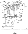
- FIG. 1 schematically illustrates a gas turbine engine 20.
- the gas turbine engine 20 is disclosed herein as a two-spool turbofan that generally incorporates a fan section 22, a compressor section 24, a combustor section 26 and a turbine section 28.
- the fan section 22 may include a single-stage fan 42 having a plurality of fan blades 43.
- the fan blades 43 may have a fixed stagger angle or may have a variable pitch to direct incoming airflow from an engine inlet.
- the fan 42 drives air along a bypass flow path B in a bypass duct 13 defined within a housing 15 such as a fan case or nacelle, and also drives air along a core flow path C for compression and communication into the combustor section 26 then expansion through the turbine section 28.
- a splitter 29 aft of the fan 42 divides the air between the bypass flow path B and the core flow path C.
- the housing 15 may surround the fan 42 to establish an outer diameter of the bypass duct 13.
- the splitter 29 may establish an inner diameter of the bypass duct 13.
- the exemplary engine 20 generally includes a low speed spool 30 and a high speed spool 32 mounted for rotation about an engine central longitudinal axis A relative to an engine static structure 36 via several bearing systems 38. It should be understood that various bearing systems 38 at various locations may alternatively or additionally be provided, and the location of bearing systems 38 may be varied as appropriate to the application.
- the low speed spool 30 generally includes an inner shaft 40 that interconnects, a first (or low) pressure compressor 44 and a first (or low) pressure turbine 46.
- the inner shaft 40 is connected to the fan 42 through a speed change mechanism, which in the exemplary gas turbine engine 20 is illustrated as a geared architecture 48 to drive the fan 42 at a lower speed than the low speed spool 30.
- the inner shaft 40 may interconnect the low pressure compressor 44 and low pressure turbine 46 such that the low pressure compressor 44 and low pressure turbine 46 are rotatable at a common speed and in a common direction.
- the low pressure turbine 46 drives both the fan 42 and low pressure compressor 44 through the geared architecture 48 such that the fan 42 and low pressure compressor 44 are rotatable at a common speed.
- the high speed spool 32 includes an outer shaft 50 that interconnects a second (or high) pressure compressor 52 and a second (or high) pressure turbine 54.
- a combustor 56 is arranged in the exemplary gas turbine 20 between the high pressure compressor 52 and the high pressure turbine 54.
- a mid-turbine frame 57 of the engine static structure 36 may be arranged generally between the high pressure turbine 54 and the low pressure turbine 46.
- the mid-turbine frame 57 further supports bearing systems 38 in the turbine section 28.
- the inner shaft 40 and the outer shaft 50 are concentric and rotate via bearing systems 38 about the engine central longitudinal axis A which is collinear with their longitudinal axes.
- Airflow in the core flow path C is compressed by the low pressure compressor 44 then the high pressure compressor 52, mixed and burned with fuel in the combustor 56, then expanded through the high pressure turbine 54 and low pressure turbine 46.
- the mid-turbine frame 57 includes airfoils 59 which are in the core flow path C.
- the turbines 46, 54 rotationally drive the respective low speed spool 30 and high speed spool 32 in response to the expansion.
- gear system 48 may be located aft of the low pressure compressor, or aft of the combustor section 26 or even aft of turbine section 28, and fan 42 may be positioned forward or aft of the location of gear system 48.
- the low pressure compressor 44, high pressure compressor 52, high pressure turbine 54 and low pressure turbine 46 each include one or more stages having a row of rotatable airfoils. Each stage may include a row of vanes adjacent the rotatable airfoils.
- the rotatable airfoils are schematically indicated at 60, and the vanes are schematically indicated at 66.
- the engine 20 may be a high-bypass geared aircraft engine.
- the bypass ratio can be greater than or equal to 10.0 and less than or equal to about 18.0, or more narrowly can be less than or equal to 16.0.
- the geared architecture 48 may be an epicyclic gear train, such as a planetary gear system or a star gear system.
- the epicyclic gear train may include a sun gear, a ring gear, a plurality of intermediate gears meshing with the sun gear and ring gear, and a carrier that supports the intermediate gears.
- the sun gear may provide an input to the gear train.
- the ring gear (e.g., star gear system) or carrier (e.g., planetary gear system) may provide an output of the gear train to drive the fan 42.
- a gear reduction ratio may be greater than or equal to 2.3, or more narrowly greater than or equal to 3.0, and in some embodiments the gear reduction ratio is greater than or equal to 3.4.
- the gear reduction ratio may be less than or equal to 4.0.
- the fan diameter is significantly larger than that of the low pressure compressor 44.
- the low pressure turbine 46 can have a pressure ratio that is greater than or equal to 8.0 and in some embodiments is greater than or equal to 10.0.
- the low pressure turbine pressure ratio can be less than or equal to 13.0, or more narrowly less than or equal to 12.0.
- Low pressure turbine 46 pressure ratio is pressure measured prior to an inlet of low pressure turbine 46 as related to the pressure at the outlet of the low pressure turbine 46 prior to an exhaust nozzle. It should be understood, however, that the above parameters are only exemplary of one embodiment of a geared architecture engine and that the present invention is applicable to other gas turbine engines including direct drive turbofans. All of these parameters are measured at the cruise condition described below.
- the fan section 22 of the engine 20 is designed for a particular flight condition -- typically cruise at about 0.8 Mach and about 35,000 feet (10,668 meters).
- the flight condition of 0.8 Mach and 35,000 ft (10,668 meters), with the engine at its best fuel consumption - also known as "bucket cruise Thrust Specific Fuel Consumption ('TSFC')" - is the industry standard parameter of lbm of fuel being burned divided by lbf of thrust the engine produces at that minimum point.
- 'TSFC' Thrust Specific Fuel Consumption
- Fan pressure ratio is the pressure ratio across the fan blade 43 alone, without a Fan Exit Guide Vane (“FEGV”) system.
- a distance is established in a radial direction between the inner and outer diameters of the bypass duct 13 at an axial position corresponding to a leading edge of the splitter 29 relative to the engine central longitudinal axis A.
- the fan pressure ratio is a spanwise average of the pressure ratios measured across the fan blade 43 alone over radial positions corresponding to the distance.
- the fan pressure ratio can be less than or equal to 1.45, or more narrowly greater than or equal to 1.25, such as between 1.30 and 1.40.
- the corrected fan tip speed can be less than or equal to 1150.0 ft / second (350.5 meters/second), and can be greater than or equal to 1000.0 ft / second (304.8 meters/second).
- the fan 42 is rotatable about an engine longitudinal axis A to deliver airflow to the bypass duct 13.
- the gas turbine engine 20 can be rated to produce about 15,000 pounds of thrust or more at a takeoff condition, or more narrowly between about 20,000 and about 60,000 pounds of thrust at the takeoff condition.
- the low pressure turbine 46 includes a low pressure (e.g., second or fan drive) turbine rotor 47 rotatable about the longitudinal axis A.
- the turbine rotor 47 can be coupled to the inner (e.g., second turbine) shaft 40.
- the turbine rotor 47 includes a disk assembly 49 which can be supported by, and can be mechanically attached or otherwise coupled to, the inner shaft 40.
- the high pressure turbine 54 includes a high pressure (e.g., first) turbine rotor 51 rotatable about the longitudinal axis A.
- the turbine rotor 51 can be coupled to the outer (e.g., first turbine) shaft 50.
- the outer shaft 50 interconnects the turbine rotor 51 and high pressure compressor 52.
- the turbine rotor 47 can be axially aft of the turbine rotor 51 relative to the engine longitudinal axis A.
- the turbine rotor 51 includes a disk assembly 53 which can be supported by, and can be mechanically attached or otherwise coupled to, the outer shaft 50.
- Each of the disk assemblies 49, 53 can carry one or more rows 55 of turbine blades 60 distributed axially with respect to the longitudinal axis A.
- the turbine blades 60 can be arranged to extract energy from combustion products communicated in the core flow path C.
- the inner shaft 40 can interconnect the disk assembly 49 and geared architecture 48 such that the turbine rotor 47 drives the fan 42 through the geared architecture 48 for propulsion.
- the geared architecture 48 is omitted such that the turbine rotor 47 drives the fan 42 at a common speed and in a common direction.
- a total number of the rows 55 of the turbine blades 60 of the high pressure turbine rotor 51 in the high pressure turbine 54 can include at least one or two rows 55, for example.
- a total number of the rows 55 of the turbine blades 60 of the low pressure turbine rotor 47 in the low pressure turbine 46 can include at least three rows 55, or more narrowly no more than six rows 55, such as four or five rows 55, for example.
- Each row 55 of turbine blades 60 can include any of the blade configurations and materials disclosed herein, including unshrouded and shrouded turbine blades constructed of ceramic matrix composite (CMC), monolithic ceramics and other ceramic materials.
- CMC ceramic matrix composite
- Each of the rows 55 can include various quantities of turbine blades 60.
- One or more, or each, row 55 of turbine blades 60 in the turbine rotor 47 and/or turbine rotor 51 can include a quantity of at least 25 turbine blades 60, or more narrowly no more than 100 turbine blades 60, such as a quantity of at least 40 turbine blades 60 but no more than 70 turbine blades 60.
- the disclosed quantities of turbine blades can be utilized in combination with the disk assemblies disclosed herein to provide a relatively lightweight turbine arrangement.
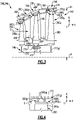
- FIG. 2 illustrates an exemplary turbine section 128.
- the turbine section 128 can be incorporated into a gas turbine engine, such as the turbofan gas turbine engine 20 of Figure 1 .
- Other portions of the engine 20 that attach airfoils including the fan section 22 and compressor section 24, and other systems may benefit from the teachings disclosed herein, including gas turbine engines lacking a fan for propulsion.
- like reference numerals designate like elements where appropriate and reference numerals with the addition of one-hundred or multiples thereof designate modified elements that are understood to incorporate the same features and benefits of the corresponding original elements.
- the turbine section 128 can include at least one turbine assembly 145.
- the turbine assembly 145 may be incorporated into the high pressure turbine 52 and/or low pressure turbine 46 of Figure 1 .
- the turbine assembly 145 is a fan drive (e.g., second) turbine 146 including a turbine rotor 147.
- the turbine rotor 147 includes a disk assembly 149 that carries one or more rows 155 of turbine blades 160.
- the rows 155 of turbine blades 160 are distributed axially in a direction X, which can be substantially parallel to the longitudinal axis A.
- Each turbine blade 160 can include an airfoil section 160 A that extends radially outward in a radial direction R from a platform 160 P to a tip 160 T relative to the longitudinal axis A.
- the platform 160 P can be integrally formed with the airfoil section 160 A or can be a separate and distinct component.
- Each turbine blade 160 includes a root section 160 R mechanically attached or otherwise secured to the disk assembly 149.
- the turbine assembly 145 can include a turbine case 161 and one or more rows 162 of turbine vanes 166 arranged downstream and axially aft of adjacent rows 155 of turbine blades 160.
- One or more rows 168 of blade outer air seals (BOAS) 170 can be arranged in an array in a circumferential or thickness direction T about and radially outward of each respective row 155 of turbine blades 160.
- the BOAS 170 are positioned in close proximity to the tips 160 T of the turbine blades 160 to establish a respective clearance gap G.
- the vanes 166 and BOAS 170 can be mechanically attached to the turbine case 161 or another portion of the engine static structure 136.
- a dimension of the clearance gap G may change during engine operation due to various factors, including thermal growth of the turbine case 161 due to relatively hot gases communicated in the core flow path C. Forces imposed on the turbine rotor 147 and other factors may cause the turbine rotor 147 to deflect relative to the engine longitudinal axis A and a dimension of the clearance gap G to change.
- the techniques disclosed herein can be utilized to reduce deflection and variation of a dimension of the clearance gap G. Lower variation may be utilized to design the turbine blades 160 to establish relatively smaller clearance gaps G, which can reduce gas path losses and improve turbine efficiency.
- the disk assembly 149 includes one or more disks 172. Each disk 172 can be dimensioned to carry or mount a respective row 155 of the turbine blades 160. Each disk 172 includes a disk portion 174 defining one or more slots 174 S distributed about an outer periphery 174 OP of the disk portion 174. The root section 160 R of the turbine blades 160 can be received in a respective one of the slot 174 S to mount the turbine blades 160 to the disk assembly 149.
- the disks 172 can be mechanically attached to each other such that the disks 172 and turbine blades 160 rotate together as a unit about the longitudinal axis A.
- the disk assembly 149 can include one or more connecting arms 176 that mechanically attach the disk portions 174 of adjacent disks 172 together with one or more fasteners F, for example.
- One or more of the disks 172 can include an attachment portion or hub 178 extending from the disk portion 174.
- the hub 178 can mechanically attach and interconnect the disk assembly 149 to the inner shaft 140 at an attachment point 179.
- the hub 178 can be dimensioned to have a relatively greater thickness and/or mass than the respective disk portion 174 as illustrated in Figure 2 , but may not contribute relatively high amounts of centrifugal loading on the disk assembly 149 due to the proximity of the hub 178 to the engine axis A.
- Figure 2 illustrates only one of the disks 172 having a hub 178, it should be understood that each of the disks 172 may have a respective hub 178 coupled to the inner shaft 140.
- the disk assembly 149 including each of the disks 172 and the respective disk portions 174 and hub(s) 178 can be constructed of a first material, and the turbine blades 160 can be constructed of a second material.
- the second material can be the same or can differ from the first material.
- the disk assembly 149 including each of the disks 172 and the respective disk portions 174 and hub 178 can comprise a metallic material, and the turbine blades 160 can comprise a ceramic matrix composite (CMC) and other ceramic material.
- the disk assembly 149 including each of the disks 172 and the respective disk portions 174 and hub(s) 178 is substantially metallic.
- a composition of each of the disks 172 may be the same or may differ.
- metallic materials can include metals and alloys, such as a nickel or cobalt-based superalloy, for example.
- the turbine blades 160 may be constructed from various ceramic materials.
- one or more (or each) of the rows 155 of the turbine blades 160 may comprise a monolithic ceramic or CMC material.
- Various CMC materials can be utilized, including one or more layers having various fiber constructions of ceramic fibers in a matrix.
- Example fiber constructions can include uni-tape plies, fabrics, two-dimensional and three-dimensional weaves of fibers.
- Uni-tape plies include fibers oriented in the same direction ("uni-directional"), and fabrics includes woven or interlaced fibers. Other fiber materials can be utilized, including carbon, aramid, and/or a combination of materials.
- An example CMC construction includes silicon carbide (SiC) composites (SiC/SiC).
- Constructing the turbine blades 160 according to the materials disclosed herein, including the airfoil section 160 A and/or the root section 160 R , can reduce centrifugal loading and structural demands on the disk assembly 149 including the disks 172, and can reduce a weight and spinning mass of the turbine rotor 147.
- a reduction in mass can reduce a moment of inertia of the turbine rotor 147 by as much as 50% or more during engine operation, which can reduce deflection of the turbine rotor 147. Reduced deflection can lead to reduced variability of a dimension of the clearance gap G, which may improve turbine efficiency.
- Each of the rows 155 of turbine blades 160 establishes a radial distance R1 between the longitudinal axis A and the radially outermost portion of the turbine blades 160.
- the radially outermost portion of the turbine blades 160 can be established by the tips 160 T of the turbine blades 160.
- the radial distance R1 is illustrated with respect to the aftmost row 155 AF of the turbine blades 160 for illustrative purposes.
- the turbine blades 160 can be dimensioned such that the radial distance R1 progressively increases in an aftwards direction for each of the rows 155 of turbine blades 160 with respect to the longitudinal axis A, as illustrated in Figure 2 .
- a first cross-sectional area A1 is defined at a downstream end of the turbine rotor 147.
- the turbine rotor 147 is rotatable at a first speed N measured at an engine redline condition.
- a performance quantity (AN 2 ) of the turbine rotor 147 is defined by the cross-sectional area A1 multiplied by the first speed N squared.
- the performance quantity can be equal to or greater than about 3.5 times 10 squared (3.5 x 10 2 ) in 2 rpm 2 , or more narrowly less than or equal to about 6.0 x 10 2 in 2 rpm 2 .
- the performance quantity can be equal to or greater than about 5.0 times 10 squared (5.0 x 10 2 ) in 2 rpm 2 .
- the first speed N can be between about 10,000 and about 15,000 rpm at the redline condition, for example.
- turbine assembly 245 includes one or more rows 255 of shrouded turbine blades 260.
- Each of the turbine blades 260 includes an airfoil section 260 A and a shroud 260 S extending from an outer periphery of the airfoil section 260 A .
- the shroud 260 S is dimensioned to face an adjacent row 268 of BOAS 270.
- each row 255 of turbine blades 260 is illustrated as a shrouded turbine blade 260 in Figure 3 , it should be understood that the turbine assembly 245 can have one or more rows of unshrouded turbine blades (see, e.g., turbine blades 160 of Figure 2 ).
- the shroud 260 S may be made of any of the materials disclosed herein, including metallic materials and/or non-metallic materials such as CMC and other ceramic materials.
- a radial distance R1 can be established in a radial direction R between the longitudinal axis A and a radially outermost portion of the turbine blades 260 relative to the longitudinal axis A.
- the radially outermost portion of the turbine blade 260 can be established by the shroud 260 S , as illustrated in Figure 3 .
- the turbine blades 260 can be dimensioned and arranged to establish any of the relationships and values disclosed herein.
- the shroud 260s can include a base portion 260 SB mechanically attached or otherwise secured to the outer periphery of the airfoil section 260 A .
- the shroud 260 S can include a first sealing feature 260 SF extending outwardly from the base portion 260 SB .
- the first sealing feature 260 SF can include one or more knife edge features 260 SN , for example.
- Each of the knife edge feature 260 SN can include various geometries extending in the axial and/or radial directions X, R.
- the knife edge features 260 SN can reduce a dynamic pressure component of the total pressure of the leakage flow through a clearance gap G between the turbine blades 260 and BOAS 270.
- Each BOAS 270 can include a second sealing feature 270 SF arranged to face the shroud 260 S .
- the first sealing feature 260 SF and second sealing feature 270 SF cooperate to establish a sealing relationship along the clearance gap G.
- the second sealing feature 270 SF can be formed from an abradable, ceramic or nickel-based alloy material, for example, such that the shroud 260 S of each turbine blade 260 cuts or machines a relatively small leakage path through the clearance gap G for all flight conditions, accounting for the different relative thermal characteristics of the shrouded blades 260, disk assembly 249 and turbine case 261, as well as the various loads and resulting deflections experienced by the turbine rotor 247.
- the reduced leakage of gases through the clearance gap G can improve overall efficiency of the turbine assembly 245.
- FIGs 5-7 illustrate a turbine assembly 345 according to another example.
- the turbine assembly 345 includes a turbine rotor 347 rotatable about a longitudinal axis A.
- the turbine rotor 347 includes a disk assembly 349 and turbine blades 360.
- the disk assembly 349 includes one or more disks 372 that carry a respective row 355 of the turbine blades 360 (one row 355 of blades 360 and one disk 372 shown for illustrative purposes, see also Figures 2-3 ).
- the turbine assembly 345 can be incorporated into any of the turbines disclosed herein, such as the turbines 46, 146 and 246 and turbine 54.
- each of the stages of the turbines 46, 54 and turbines 146, 246 can incorporate the disk 372 to establish any of the relationships and values disclosed herein.
- the disk 372 can include a disk portion 374 and may include an attachment portion or hub 378' (shown in dashed lines in Figure 7 for illustrative purposes).
- Each disk 372 includes an attachment region 380 for mounting a respective row 355 of turbine blades 360 to the disk assembly 349.
- the attachment region 380 may be established by the disk portion 374 of the disk 372.
- the attachment region 380 is dimensioned to extend radially in a radial direction R between an inner boundary 382 and an outer boundary 384 relative to an engine longitudinal axis A (boundaries 382, 384 shown in dashed lines for illustrative purposes).
- the attachment region 380 is dimensioned such that the outer boundary 384 surrounds the inner boundary 382.
- the outer boundary 384 can be established by an outer periphery 374 OP of the respective disk 372.
- the attachment region 380 can be dimensioned to react to the radial pull of the blades 360 in operation. However, the attachment region 380 may have relatively low hoop strength due to discontinuities established by the slots 374S and may therefore serve as an additional parasitic radial load on the disk 372 inward of the inner boundary 382.
- the turbine blades 360 can incorporate CMC or other ceramic materials to reduce radial loads on the attachment region 380. Because of the reduced radial loads on the attachment region 380, the attachment region 380 can be dimensioned to reduce the parasitic loads and establish a relatively lightweight turbine rotor 347.
- the attachment region 380 defines an array of slots 374 S distributed about the outer periphery 374 OP of the disk 372 and longitudinal axis A, as illustrated in Figure 7 .
- Each turbine blade 360 and slot 374 S extends in the axial, circumferential and radial directions X, T, R, as illustrated by Figures 5-7 .
- Each of the slots 374 S is dimensioned to extend radially inward in the radial direction R from the outer boundary 384 to the inner boundary 382.
- Each of the slots 374 S is dimensioned to slidably receive a root section 360 R of a respective one of the turbine blades 360 to mount the turbine blades 360 to the disk assembly 349.
- the root section 360 R may be moved in a direction D1 ( Figure 6 ) such that the root section 360 R is at least partially received into the respective slot 374 S to secure the turbine blade 360.
- the disk assembly 349 can establish a relatively high speed, compact arrangement.
- the inner boundary 382 establishes a live rim radius R L relative to the longitudinal axis A.
- the live rim radius R L may be associated with a radial outer limit where the disk 372 is capable of substantially reacting hoop stresses caused by centrifugal loads imposed by the rotating turbine blades 360.
- the outer boundary 384 establishes a dead rim radius R D relative to the longitudinal axis A.
- Each disk 372 establishes a respective disk ratio R L :R D of the live rim radius R L to the dead rim radius R D .
- the disk ratio R L :R D can be greater than or equal to about 0.8:1 for at least one or more (or each) disk 372 of the disk assembly 349.
- the disk establishing the disk ratio R L :R D according to any of the values disclosed herein can include an aftmost disk 172 AF of the disks 172 of Figure 2 and an aftmost disk 272 AF of the disks 272 of Figure 3 .
- the disclosed ratios and quantities associated with the disk 372 can be incorporated into any of the disks and turbines disclosed herein, including the turbines 46, 54 of Figure 1 and each of the disks 172, 272 of Figures 2 and 3 .
- the disk ratio R L :R D can be greater than or equal to about 0.8:1 for each one of the disks 172, 272, 372 of the turbine assemblies 145, 245, 345.
- the disk ratio R L :R D can be greater than or equal to about 0.85:1, or more narrowly less than or equal to about 0.95:1 for each one of the disks 172, 272, 372.
- the disclosed attachment techniques can be utilized in combination with CMC and other ceramic turbine blades to establish relatively high disk ratios R L :R D .
- Each row 355 of turbine blades 360 establishes a radial distance R1 between the longitudinal axis A and the radially outermost portion of the turbine blades 360, which can be established by the tips 360 T of the turbine blades 360 (shown schematically in Figure 7 for illustrative purposes).
- Each row 355 of turbine blades 360 establishes a blade ratio R D :R1 of the dead rim radius R D to the radial distance R1.
- the blade ratio R D :R1 can be less than or equal to about 0.5:1 for at least one row 355 of turbine blades 360.
- the blade ratio R D :R1 can be less than or equal to about 0.5:1 for at least the aftmost rows 155 AF , 255 AF of turbine blades 160, 260 ( Figures 2-3 ). It should be understood that the disclosed values of the blade ratio R D :R1 can be established by any and each of the blade rows and disks of the turbines disclosed herein. The disclosed blade ratios R D :R1 can be utilized in combination with the disclosed disk ratios R L :R D to establish a relatively compact turbine arrangement.
- each slot 374 S and the root section 360 R of each turbine blade 360 can have a complementary geometry to secure the root section 360 R in the respective slot 374 S .
- the attachment region 380 of the disk 372 includes an array of attachment members 386 distributed about the longitudinal axis A.
- Each attachment member 386 includes a main body 387 extending outwardly from a neck 390.
- a pair of protrusions (e.g., teeth) 388 extend outwardly from opposed sides of the main body 387.
- Protrusions 388 on opposed sides of the slot 374 S cooperate to capture or trap the root section 360 R of the turbine blade 360 in the slot 374 S to limit relative radial and circumferential movement between the turbine blade 360 and disk 372.
- the protrusions 388 may establish an attachment boundary 392 (shown in dashed lines in Figures 5 and 7 for illustrative purposes).
- the radially innermost faces of the slots 374 S establish the inner boundary 382.
- the outer boundary 384 follows the contour of the outer periphery 374 OP of the disk 372.
- the attachment boundary 392 is established between the inner boundary 382 and outer boundary 384.
- Each row 355 of turbine blades 360 defines a blade volume V B ( Figure 5 ) associated with a respective disk volume V D ( Figures 5-7 ).
- the blade volume V B is defined as a sum of portions of the turbine blades 360 between the inner boundary 382 and the outer boundary 384 captured in the slots 374 S in an installed position, as illustrated in Figure 5 .
- the disk volume V D is defined as a sum of portions of the respective disk 372 between the inner boundary 382 and the outer boundary 384 that extend between the axial faces of the respective disk 372.
- the disk volume V D can be established by at least the attachment region 380.
- the disk 372 and respective row 355 of turbine blades 360 establish a volumetric ratio V B :V D of the blade volume V B to the disk volume V D .
- the disclosed attachment region 380 can be utilized to establish a relatively high volumetric ratio V B :V D .
- the volumetric ratio V B :V D can be equal to or greater than 2.0:1, or more narrowly less than or equal to 4.0:1, for at least one or more (or each) disk 372 of the turbine 345.
- Turbine blades 360 made of a monolithic ceramic may be utilized to establish volumetric ratios V B :V D that are equal to about 2.0:1, for example.
- Turbine blades 360 incorporating CMC materials may be utilized to establish volumetric ratios V B :V D that are equal to or greater than 2.5:1, or more narrowly less than or equal to 3.5:1, such as about 3.0, which may provide an even more compact turbine arrangement.
- the disclosed volumetric ratios V B :V D can be utilized to reduce a mass of the disk 372 in the attachment region 380, including relatively greater proportions of ceramic materials, which can reduce deflection of the turbine rotor 347 and variation in a dimension of the clearance gap G (see, e.g., Figure 2 ) which can improve efficiency, and can reduce an overall weight of the engine.
- the attachment members 386 can be dimensioned to establish a relatively high volumetric ratio V B :V D .
- a minimum width of the neck 390 establishes a first width W1.
- a minimum width of the adjacent slot 374 S establishes a second width W2.
- the second width W2 can be established between opposed protrusions 388.
- a width of the turbine blade 360 received in the respective slot 374 S can be substantially equal to the second width W2.
- the second width W2 may be established along the attachment boundary 392.
- a ratio W1:W2 of the first width W1 to the second width W2 may be less than or equal to about 0.5:1, or more narrowly less than or equal to about 0.35:1. Ratios W1:W2 of less than or equal to about 0.25:1 may establish even greater volumetric ratios V B :V D .
- the disclosed attachment techniques and incorporation of turbine blades including CMC and other ceramic materials can be utilized to reduce a weight of the disk assembly and increase rotational speeds while maintaining a determined disk size and weight sufficient to carry the turbine blades in operation.
- Reductions in turbine weight may reduce an overall weight of the engine and improve efficiency.
- the reduced spinning mass may also reduce deflection of the turbine rotor, which can improve turbine efficiency.
Landscapes
- Engineering & Computer Science (AREA)
- Mechanical Engineering (AREA)
- General Engineering & Computer Science (AREA)
- Chemical & Material Sciences (AREA)
- Combustion & Propulsion (AREA)
- Turbine Rotor Nozzle Sealing (AREA)
Applications Claiming Priority (1)
| Application Number | Priority Date | Filing Date | Title |
|---|---|---|---|
| US17/146,541 US11608750B2 (en) | 2021-01-12 | 2021-01-12 | Airfoil attachment for turbine rotor |
Publications (2)
| Publication Number | Publication Date |
|---|---|
| EP4026986A2 true EP4026986A2 (fr) | 2022-07-13 |
| EP4026986A3 EP4026986A3 (fr) | 2022-11-16 |
Family
ID=79316685
Family Applications (1)
| Application Number | Title | Priority Date | Filing Date |
|---|---|---|---|
| EP22151234.6A Pending EP4026986A3 (fr) | 2021-01-12 | 2022-01-12 | Fixation de surface portante pour rotor d'éolienne |
Country Status (2)
| Country | Link |
|---|---|
| US (2) | US11608750B2 (fr) |
| EP (1) | EP4026986A3 (fr) |
Cited By (9)
| Publication number | Priority date | Publication date | Assignee | Title |
|---|---|---|---|---|
| FR3143675A1 (fr) * | 2022-12-16 | 2024-06-21 | Safran Aircraft Engines | Système propulsif aéronautique |
| FR3143685A1 (fr) * | 2022-12-16 | 2024-06-21 | Safran Aircraft Engines | Systeme propulsif aeronautique |
| FR3143657A1 (fr) * | 2022-12-16 | 2024-06-21 | Safran Aircraft Engines | Système propulsif aéronautique |
| FR3143678A1 (fr) * | 2022-12-16 | 2024-06-21 | Safran Aircraft Engines | Système propulsif aéronautique |
| FR3143683A1 (fr) * | 2022-12-16 | 2024-06-21 | Safran Aircraft Engines | Systeme propulsif aeronautique |
| FR3143681A1 (fr) * | 2022-12-16 | 2024-06-21 | Safran Aircraft Engines | Système propulsif aéronautique |
| FR3143674A1 (fr) * | 2022-12-16 | 2024-06-21 | Safran Aircraft Engines | Systeme propulsif aeronautique |
| FR3143671A1 (fr) * | 2022-12-16 | 2024-06-21 | Safran Aircraft Engines | Système propulsif aéronautique |
| US12313008B2 (en) | 2022-12-16 | 2025-05-27 | Safran Aircraft Engines | Aeronautical propulsion system |
Families Citing this family (1)
| Publication number | Priority date | Publication date | Assignee | Title |
|---|---|---|---|---|
| US11608750B2 (en) * | 2021-01-12 | 2023-03-21 | Raytheon Technologies Corporation | Airfoil attachment for turbine rotor |
Citations (1)
| Publication number | Priority date | Publication date | Assignee | Title |
|---|---|---|---|---|
| US20140109548A1 (en) * | 2012-09-28 | 2014-04-24 | United Technologies Corporation | High pressure rotor disk |
Family Cites Families (21)
| Publication number | Priority date | Publication date | Assignee | Title |
|---|---|---|---|---|
| US4767274A (en) * | 1986-12-29 | 1988-08-30 | United Technologies Corporation | Multiple lug blade to disk attachment |
| GB2237846B (en) * | 1989-11-09 | 1993-12-15 | Rolls Royce Plc | Rim parasitic weight reduction |
| US5846054A (en) * | 1994-10-06 | 1998-12-08 | General Electric Company | Laser shock peened dovetails for disks and blades |
| US6857856B2 (en) | 2002-09-27 | 2005-02-22 | Florida Turbine Technologies, Inc. | Tailored attachment mechanism for composite airfoils |
| JP4584102B2 (ja) * | 2005-09-30 | 2010-11-17 | 株式会社日立製作所 | タービンロータと逆クリスマスツリー型タービン動翼及びそれを用いた低圧蒸気タービン並びに蒸気タービン発電プラント |
| JP2007231868A (ja) * | 2006-03-02 | 2007-09-13 | Hitachi Ltd | 蒸気タービン動翼およびそれを用いた蒸気タービン並びに蒸気タービン発電プラント |
| US7661924B2 (en) * | 2007-03-28 | 2010-02-16 | General Electric Company | Method and apparatus for assembling turbine engines |
| US8844265B2 (en) * | 2007-08-01 | 2014-09-30 | United Technologies Corporation | Turbine section of high bypass turbofan |
| US8221083B2 (en) * | 2008-04-15 | 2012-07-17 | United Technologies Corporation | Asymmetrical rotor blade fir-tree attachment |
| US8573947B2 (en) | 2010-03-10 | 2013-11-05 | United Technologies Corporation | Composite fan blade dovetail root |
| US8721290B2 (en) * | 2010-12-23 | 2014-05-13 | General Electric Company | Processes for producing components containing ceramic-based and metallic materials |
| US8920127B2 (en) | 2011-07-18 | 2014-12-30 | United Technologies Corporation | Turbine rotor non-metallic blade attachment |
| US20130192265A1 (en) * | 2012-01-31 | 2013-08-01 | Frederick M. Schwarz | Gas turbine engine with high speed low pressure turbine section and bearing support features |
| US20130192266A1 (en) | 2012-01-31 | 2013-08-01 | United Technologies Corporation | Geared turbofan gas turbine engine architecture |
| US9932831B2 (en) * | 2014-05-09 | 2018-04-03 | United Technologies Corporation | High temperature compliant metallic elements for low contact stress ceramic support |
| FR3031136B1 (fr) * | 2014-12-26 | 2019-11-01 | Safran Aircraft Engines | Rotor de turbomachine a surfaces d'appui optimisees |
| US10458268B2 (en) * | 2016-04-13 | 2019-10-29 | Rolls-Royce North American Technologies Inc. | Turbine shroud with sealed box segments |
| KR102176954B1 (ko) * | 2017-09-14 | 2020-11-10 | 두산중공업 주식회사 | 가스 터빈용 압축기 로터 디스크 |
| US10655479B2 (en) | 2018-07-11 | 2020-05-19 | Rolls-Royce Corporation | Turbine wheel assembly with ceramic matrix composite blades |
| GB201820934D0 (en) * | 2018-12-21 | 2019-02-06 | Rolls Royce Plc | Low fan noise geared gas turbine engine |
| US11608750B2 (en) * | 2021-01-12 | 2023-03-21 | Raytheon Technologies Corporation | Airfoil attachment for turbine rotor |
-
2021
- 2021-01-12 US US17/146,541 patent/US11608750B2/en active Active
-
2022
- 2022-01-12 EP EP22151234.6A patent/EP4026986A3/fr active Pending
-
2023
- 2023-03-20 US US18/123,547 patent/US12247497B2/en active Active
Patent Citations (1)
| Publication number | Priority date | Publication date | Assignee | Title |
|---|---|---|---|---|
| US20140109548A1 (en) * | 2012-09-28 | 2014-04-24 | United Technologies Corporation | High pressure rotor disk |
Cited By (19)
| Publication number | Priority date | Publication date | Assignee | Title |
|---|---|---|---|---|
| FR3143675A1 (fr) * | 2022-12-16 | 2024-06-21 | Safran Aircraft Engines | Système propulsif aéronautique |
| FR3143685A1 (fr) * | 2022-12-16 | 2024-06-21 | Safran Aircraft Engines | Systeme propulsif aeronautique |
| FR3143657A1 (fr) * | 2022-12-16 | 2024-06-21 | Safran Aircraft Engines | Système propulsif aéronautique |
| FR3143658A1 (fr) * | 2022-12-16 | 2024-06-21 | Safran Aircraft Engines | système PROPULSIF AERONAUTIQUE |
| FR3143679A1 (fr) * | 2022-12-16 | 2024-06-21 | Safran Aircraft Engines | Système propulsif aéronautique |
| FR3143678A1 (fr) * | 2022-12-16 | 2024-06-21 | Safran Aircraft Engines | Système propulsif aéronautique |
| FR3143683A1 (fr) * | 2022-12-16 | 2024-06-21 | Safran Aircraft Engines | Systeme propulsif aeronautique |
| FR3143681A1 (fr) * | 2022-12-16 | 2024-06-21 | Safran Aircraft Engines | Système propulsif aéronautique |
| FR3143661A1 (fr) * | 2022-12-16 | 2024-06-21 | Safran Aircraft Engines | système PROPULSIF AERONAUTIQUE |
| FR3143682A1 (fr) * | 2022-12-16 | 2024-06-21 | Safran Aircraft Engines | Système propulsif aéronautique |
| FR3143662A1 (fr) * | 2022-12-16 | 2024-06-21 | Safran Aircraft Engines | Système propulsif aéronautique |
| FR3143674A1 (fr) * | 2022-12-16 | 2024-06-21 | Safran Aircraft Engines | Systeme propulsif aeronautique |
| FR3143663A1 (fr) * | 2022-12-16 | 2024-06-21 | Safran Aircraft Engines | système PROPULSIF AERONAUTIQUE |
| FR3143680A1 (fr) * | 2022-12-16 | 2024-06-21 | Safran Aircraft Engines | Système propulsif aéronautique |
| FR3143671A1 (fr) * | 2022-12-16 | 2024-06-21 | Safran Aircraft Engines | Système propulsif aéronautique |
| US12123317B2 (en) | 2022-12-16 | 2024-10-22 | Safran Aircraft Engines | Aeronautical propulsion system |
| US12286904B2 (en) | 2022-12-16 | 2025-04-29 | Safran Aircraft Engines | Blade and slotted rotor wheel for a gas turbine engine |
| US12313008B2 (en) | 2022-12-16 | 2025-05-27 | Safran Aircraft Engines | Aeronautical propulsion system |
| US12398672B2 (en) | 2022-12-16 | 2025-08-26 | Safran Aircraft Engines | Aeronautical propulsion system |
Also Published As
| Publication number | Publication date |
|---|---|
| EP4026986A3 (fr) | 2022-11-16 |
| US11608750B2 (en) | 2023-03-21 |
| US12247497B2 (en) | 2025-03-11 |
| US20220220895A1 (en) | 2022-07-14 |
| US20230250728A1 (en) | 2023-08-10 |
Similar Documents
| Publication | Publication Date | Title |
|---|---|---|
| US12247497B2 (en) | Airfoil attachment for turbine rotor | |
| US10436035B1 (en) | Fan design | |
| EP3608509B1 (fr) | Moteur de turbine à gaz avec composants de turbine en composite à matrice céramique | |
| US10738693B2 (en) | Advanced gas turbine engine | |
| US12146440B2 (en) | Efficient aircraft engine | |
| US20200049021A1 (en) | Turbine arrangement for a gas turbine engine | |
| US12454917B2 (en) | Gas turbine engine | |
| US20220307448A1 (en) | Efficient gas turbine engine | |
| US20200049065A1 (en) | Aircraft engine temperature control and capability | |
| US11549373B2 (en) | Reduced deflection turbine rotor | |
| GB2594712A (en) | Vane assembly for gas turbine engine | |
| US11466617B2 (en) | Gas turbine engine with efficient thrust generation | |
| US20160003163A1 (en) | Gas turbine engine with short transition duct | |
| US12331654B2 (en) | Bathtub seal for damping CMC vane platform | |
| US20200049067A1 (en) | Aircraft engine with high propulsive and thermal efficiency | |
| US11156110B1 (en) | Rotor assembly for a turbine section of a gas turbine engine | |
| EP3597870B1 (fr) | Turbine à gaz | |
| US12326099B2 (en) | Bathtub seal integrated into CMC vane load path | |
| EP4596842A1 (fr) | Section de turbine pour un moteur à turbine à gaz, moteur à turbine à gaz et procédé pour fixer un joint d'air extérieur d'aube mobile à une structure statique d'un moteur à turbine à gaz |
Legal Events
| Date | Code | Title | Description |
|---|---|---|---|
| PUAI | Public reference made under article 153(3) epc to a published international application that has entered the european phase |
Free format text: ORIGINAL CODE: 0009012 |
|
| STAA | Information on the status of an ep patent application or granted ep patent |
Free format text: STATUS: THE APPLICATION HAS BEEN PUBLISHED |
|
| AK | Designated contracting states |
Kind code of ref document: A2 Designated state(s): AL AT BE BG CH CY CZ DE DK EE ES FI FR GB GR HR HU IE IS IT LI LT LU LV MC MK MT NL NO PL PT RO RS SE SI SK SM TR |
|
| PUAL | Search report despatched |
Free format text: ORIGINAL CODE: 0009013 |
|
| AK | Designated contracting states |
Kind code of ref document: A3 Designated state(s): AL AT BE BG CH CY CZ DE DK EE ES FI FR GB GR HR HU IE IS IT LI LT LU LV MC MK MT NL NO PL PT RO RS SE SI SK SM TR |
|
| RIC1 | Information provided on ipc code assigned before grant |
Ipc: F01D 5/02 20060101ALI20221011BHEP Ipc: F01D 5/28 20060101ALI20221011BHEP Ipc: F01D 5/30 20060101AFI20221011BHEP |
|
| STAA | Information on the status of an ep patent application or granted ep patent |
Free format text: STATUS: REQUEST FOR EXAMINATION WAS MADE |
|
| 17P | Request for examination filed |
Effective date: 20230516 |
|
| RBV | Designated contracting states (corrected) |
Designated state(s): AL AT BE BG CH CY CZ DE DK EE ES FI FR GB GR HR HU IE IS IT LI LT LU LV MC MK MT NL NO PL PT RO RS SE SI SK SM TR |
|
| RAP3 | Party data changed (applicant data changed or rights of an application transferred) |
Owner name: RTX CORPORATION |
|
| STAA | Information on the status of an ep patent application or granted ep patent |
Free format text: STATUS: EXAMINATION IS IN PROGRESS |
|
| 17Q | First examination report despatched |
Effective date: 20240926 |