EP4027059A1 - Burner, combustor, and method for retrofitting a combustion appliance - Google Patents
Burner, combustor, and method for retrofitting a combustion appliance Download PDFInfo
- Publication number
- EP4027059A1 EP4027059A1 EP21151199.3A EP21151199A EP4027059A1 EP 4027059 A1 EP4027059 A1 EP 4027059A1 EP 21151199 A EP21151199 A EP 21151199A EP 4027059 A1 EP4027059 A1 EP 4027059A1
- Authority
- EP
- European Patent Office
- Prior art keywords
- duct
- fluid
- plenum
- downstream
- burner
- Prior art date
- Legal status (The legal status is an assumption and is not a legal conclusion. Google has not performed a legal analysis and makes no representation as to the accuracy of the status listed.)
- Withdrawn
Links
- 238000002485 combustion reaction Methods 0.000 title claims description 100
- 238000000034 method Methods 0.000 title claims description 7
- 238000009420 retrofitting Methods 0.000 title claims description 4
- 239000012530 fluid Substances 0.000 claims abstract description 206
- 238000007599 discharging Methods 0.000 claims abstract description 21
- 238000011144 upstream manufacturing Methods 0.000 claims description 63
- 238000005192 partition Methods 0.000 claims description 25
- 239000002826 coolant Substances 0.000 claims description 23
- 238000004891 communication Methods 0.000 claims description 12
- 230000002093 peripheral effect Effects 0.000 claims description 7
- 239000000446 fuel Substances 0.000 description 116
- 239000001257 hydrogen Substances 0.000 description 25
- 229910052739 hydrogen Inorganic materials 0.000 description 25
- UFHFLCQGNIYNRP-UHFFFAOYSA-N Hydrogen Chemical compound [H][H] UFHFLCQGNIYNRP-UHFFFAOYSA-N 0.000 description 22
- MWUXSHHQAYIFBG-UHFFFAOYSA-N Nitric oxide Chemical compound O=[N] MWUXSHHQAYIFBG-UHFFFAOYSA-N 0.000 description 18
- 239000003795 chemical substances by application Substances 0.000 description 18
- VNWKTOKETHGBQD-UHFFFAOYSA-N methane Chemical compound C VNWKTOKETHGBQD-UHFFFAOYSA-N 0.000 description 18
- 238000001816 cooling Methods 0.000 description 14
- 239000007788 liquid Substances 0.000 description 14
- 238000002156 mixing Methods 0.000 description 12
- 239000007789 gas Substances 0.000 description 10
- 239000000203 mixture Substances 0.000 description 10
- 239000003345 natural gas Substances 0.000 description 9
- 206010016754 Flashback Diseases 0.000 description 8
- 230000015572 biosynthetic process Effects 0.000 description 8
- 239000007800 oxidant agent Substances 0.000 description 8
- XLYOFNOQVPJJNP-UHFFFAOYSA-N water Substances O XLYOFNOQVPJJNP-UHFFFAOYSA-N 0.000 description 8
- 238000009792 diffusion process Methods 0.000 description 6
- 230000003647 oxidation Effects 0.000 description 6
- 238000007254 oxidation reaction Methods 0.000 description 6
- 239000002737 fuel gas Substances 0.000 description 5
- 230000001965 increasing effect Effects 0.000 description 5
- 238000004519 manufacturing process Methods 0.000 description 5
- 230000001590 oxidative effect Effects 0.000 description 4
- 239000000654 additive Substances 0.000 description 3
- 230000000996 additive effect Effects 0.000 description 3
- 150000002431 hydrogen Chemical class 0.000 description 3
- 238000002347 injection Methods 0.000 description 3
- 239000007924 injection Substances 0.000 description 3
- IJGRMHOSHXDMSA-UHFFFAOYSA-N Atomic nitrogen Chemical compound N#N IJGRMHOSHXDMSA-UHFFFAOYSA-N 0.000 description 2
- 230000001419 dependent effect Effects 0.000 description 2
- 238000013461 design Methods 0.000 description 2
- 238000010790 dilution Methods 0.000 description 2
- 239000012895 dilution Substances 0.000 description 2
- 230000000694 effects Effects 0.000 description 2
- 238000007789 sealing Methods 0.000 description 2
- 239000007921 spray Substances 0.000 description 2
- 239000013598 vector Substances 0.000 description 2
- 239000004215 Carbon black (E152) Substances 0.000 description 1
- 238000010793 Steam injection (oil industry) Methods 0.000 description 1
- 230000008033 biological extinction Effects 0.000 description 1
- 125000004432 carbon atom Chemical group C* 0.000 description 1
- 238000000576 coating method Methods 0.000 description 1
- 238000011161 development Methods 0.000 description 1
- -1 for instance Chemical compound 0.000 description 1
- 229930195733 hydrocarbon Natural products 0.000 description 1
- 150000002430 hydrocarbons Chemical class 0.000 description 1
- 230000001976 improved effect Effects 0.000 description 1
- 230000001939 inductive effect Effects 0.000 description 1
- 239000000463 material Substances 0.000 description 1
- 239000011159 matrix material Substances 0.000 description 1
- 230000000116 mitigating effect Effects 0.000 description 1
- 229910052757 nitrogen Inorganic materials 0.000 description 1
- 238000013021 overheating Methods 0.000 description 1
- 238000010926 purge Methods 0.000 description 1
- 230000009257 reactivity Effects 0.000 description 1
- 230000006641 stabilisation Effects 0.000 description 1
- 238000011105 stabilization Methods 0.000 description 1
- 230000008093 supporting effect Effects 0.000 description 1
- 230000007704 transition Effects 0.000 description 1
Images


Classifications
-
- F—MECHANICAL ENGINEERING; LIGHTING; HEATING; WEAPONS; BLASTING
- F23—COMBUSTION APPARATUS; COMBUSTION PROCESSES
- F23R—GENERATING COMBUSTION PRODUCTS OF HIGH PRESSURE OR HIGH VELOCITY, e.g. GAS-TURBINE COMBUSTION CHAMBERS
- F23R3/00—Continuous combustion chambers using liquid or gaseous fuel
- F23R3/28—Continuous combustion chambers using liquid or gaseous fuel characterised by the fuel supply
- F23R3/286—Continuous combustion chambers using liquid or gaseous fuel characterised by the fuel supply having fuel-air premixing devices
-
- F—MECHANICAL ENGINEERING; LIGHTING; HEATING; WEAPONS; BLASTING
- F23—COMBUSTION APPARATUS; COMBUSTION PROCESSES
- F23D—BURNERS
- F23D14/00—Burners for combustion of a gas, e.g. of a gas stored under pressure as a liquid
- F23D14/02—Premix gas burners, i.e. in which gaseous fuel is mixed with combustion air upstream of the combustion zone
-
- F—MECHANICAL ENGINEERING; LIGHTING; HEATING; WEAPONS; BLASTING
- F23—COMBUSTION APPARATUS; COMBUSTION PROCESSES
- F23R—GENERATING COMBUSTION PRODUCTS OF HIGH PRESSURE OR HIGH VELOCITY, e.g. GAS-TURBINE COMBUSTION CHAMBERS
- F23R3/00—Continuous combustion chambers using liquid or gaseous fuel
- F23R3/02—Continuous combustion chambers using liquid or gaseous fuel characterised by the air-flow or gas-flow configuration
- F23R3/04—Air inlet arrangements
- F23R3/10—Air inlet arrangements for primary air
- F23R3/12—Air inlet arrangements for primary air inducing a vortex
- F23R3/14—Air inlet arrangements for primary air inducing a vortex by using swirl vanes
-
- F—MECHANICAL ENGINEERING; LIGHTING; HEATING; WEAPONS; BLASTING
- F23—COMBUSTION APPARATUS; COMBUSTION PROCESSES
- F23R—GENERATING COMBUSTION PRODUCTS OF HIGH PRESSURE OR HIGH VELOCITY, e.g. GAS-TURBINE COMBUSTION CHAMBERS
- F23R2900/00—Special features of, or arrangements for continuous combustion chambers; Combustion processes therefor
- F23R2900/00002—Gas turbine combustors adapted for fuels having low heating value [LHV]
-
- F—MECHANICAL ENGINEERING; LIGHTING; HEATING; WEAPONS; BLASTING
- F23—COMBUSTION APPARATUS; COMBUSTION PROCESSES
- F23R—GENERATING COMBUSTION PRODUCTS OF HIGH PRESSURE OR HIGH VELOCITY, e.g. GAS-TURBINE COMBUSTION CHAMBERS
- F23R2900/00—Special features of, or arrangements for continuous combustion chambers; Combustion processes therefor
- F23R2900/00016—Retrofitting in general, e.g. to respect new regulations on pollution
Definitions
- the present disclosure relates to the subject matter set forth in the claims.
- it relates to a burner It further relates to a combustor and a gas turbine engine incorporating the burner and a method for retrofitting a combustion appliance
- combustion systems and burners are known for the combustion of a fuel with low nitric oxide generation.
- the fuel in particular a gaseous fuel
- the oxidant is most commonly air.
- air will be used to generically denote any oxidant.
- the skilled person will, by virtue of the aforesaid, readily understand the mention of air in the following as a disclosure of a generic oxidant. "Air”, to this extent, shall be broadly construed to represent a generic oxidant.
- premixed flames yield the issue of combustion stability, as they are generally operated at an equivalence ratio rather close to the lower extinction limit.
- the premix flames, or some of the premix flames are replaced with, or supported by, so-called piloting flames. These are flames combusting less intensely premixed or even essentially non-premixed fuel-air mixtures, comprising zones of richer fuel-air mixture and thus providing for higher local combustion temperatures and yielding a combustion less sensitive to external influences.
- piloting flames are flames combusting less intensely premixed or even essentially non-premixed fuel-air mixtures, comprising zones of richer fuel-air mixture and thus providing for higher local combustion temperatures and yielding a combustion less sensitive to external influences.
- nitric oxide formation increases disproportionally with the combustion temperature, and hence a balance needs to be found between nitric oxide formation and combustion stability.
- Diffusion flames combusting a stream of fuel and air with zones having equivalent ratios close to 1, i.e. near stoichiometric zones, yield excellent combustion stability, but with high nitric oxide formation. It is hence a goal in burner development and combustion engineering to design burners and operation concepts which yield minimum combustion instabilities in lean premix combustion and/or enable combustion over a large range of operation with as little piloting as possible.
- premix burners on, for instance, hydrogen or hydrogen-rich mixtures as fuel increases the risk of flame flashback and burner overheating, which need to be accounted for.
- fuels yielding, generally spoken, higher flammability than for instance natural gas.
- the combustion of hydrogen yields a higher flame temperature when compared to the combustion of natural gas, which might result in an increased formation of nitric oxides.
- US 6,267,585 suggests the combustion of hydrogen by directly injecting hydrogen into air jets from perforated blades, by which the hydrogen is combusted in micro diffusion flames.
- the document states that in reducing the perforation matrix size of the perforated blades nitric oxide levels of as low as 10 ppmv (parts per million, volumetric) can be achieved.
- a burner type sometimes referred to as cluster burner or micro tube cluster burner is known in the art and the suggested for the combustion of hydrogen.
- These generally comprise mixing tubes which are intended to be flown through by air and which extend through a fuel plenum.
- the mixing tubes are in fluid communication with the fluid plenum, whereby the fuel can be mixed into the combustion air stream through the mixing tubes.
- US 2013/0232979 discloses a burner comprising mixing tubes which extend through a fuel plenum. Nozzles extend into the mixing tubes for discharging fuel from the fuel plenum into the mixing tubes.
- WO 2015/182154 and US 2010/0218501 disclose further examples of burners of similar structure and function.
- US 2016/033133 suggests an arrangement of a multitude of individual cluster burner modules side by side, wherein each cluster burner module comprises an individual fuel plenum and is equipped with an individual supply line.
- US 2015/076251 describes a cluster burner in which the mixing tubes are combined with a fuel cartridge. Furthermore, a cooling air plenum is provided downstream of the fuel plenum.
- the cooling air plenum discharges the cooling air through the downstream front wall of the burner for effecting effusion and film cooling and is not fluidly connected to the mixing tubes.
- US 4,100,733 suggests a microtube cluster burner in which radially inner and radially outer micro tubes are arranged to be fed with fuel from distinct fuel plenums. In embodiments, the fuel plenums are stacked along the throughflow direction of the microtubes.
- a burner shall be disclosed which avoids the drawbacks of the art outlined above.
- a burner shall be proposed which enables the combustion of hydrogen or hydrogen rich fuel or other highly reactive fuel gases or fuel gas mixtures in a wide load range and with minimized flashback risk and nitric oxide formation.
- gases and gas mixtures are, generally spoken, characterized by at least one of a significantly short autoignition time, significantly higher flame velocity, and a significantly broader range of the equivalence ratio in which they are flammable.
- a burner shall be proposed which allows robust lean premix operation over a wide load range with minimized flame blowoff risk.
- the burner shall be suitable for operation on a wide range of fuels.
- the burner shall enable the use of, in addition to fuel, inert fluids for purposes of, for instance, while not limited to, reducing nitric oxide formation, mitigating potential flashback issues, and other purposes.
- the burner shall be suitable to replace existing burners in legacy combustors or combustion appliances, like for instance, while not limited to, gas turbine combustors.
- upgrading of legacy combustors may enable those combustors to be operated on fuels for which the legacy burners to be replaced were not suitable or inhibited limitations.
- upgrading may also be suitable to enhance fuel flexibility, emissions, operating range and other characteristics of a legacy combustor.
- a legacy combustor may be upgraded for the combustion of hydrogen.
- a burner comprising a first, upstream front wall and a second, downstream front wall.
- a general airflow direction is defined from the first front wall to the second front wall.
- the terms upstream and downstream used in the context of the herein described burner shall be understood as referring to the general airflow direction from the first, upstream, front wall to the second, downstream front wall, unless defined differently in the specific context. It is noted that generally a skilled person will be able to determine which of the front walls is intended to serve as the downstream front wall.
- the downstream front wall generally is, implicitly, intended to be provided bordering a combustion space and may thus define in terms of material use, cooling features, coatings and other features characteristic of a downstream front wall of a burner and by which the skilled person will readily distinguish the downstream front wall from the upstream front wall.
- At least one partition wall extends across the general airflow direction and between the first and second front walls, whereby the at least one partition wall divides a space between the upstream front wall and the downstream front wall into at least two separate fluid plenums stacked along the general airflow direction.
- the front walls and partition walls may in the following also be referred to as the "transverse walls".
- the burner further comprises at least one peripheral wall extending between at least one of the front walls, at least two partition walls, and/or a front wall and a partition wall.
- the peripheral wall may in particular be leak-proof connected to the transverse walls to which it extends along the circumference of the respective transverse wall, thus forming an essentially closed plenum between the respective transverse walls.
- the peripheral wall may extend from the upstream front wall to the downstream front wall and be leak-proof connected to the upstream and downstream front walls along their respective circumference and further in particular to all partition walls along their respective circumference.
- the peripheral wall may extend from the upstream front wall to the most downstream partition wall and be leak-proof connected to the upstream front wall and the most downstream partition wall along their respective circumference, and further in particular to all interposed partition walls along their respective circumference.
- the most downstream plenum formed between the most downstream partition wall and the downstream front wall may in particular be intended to be used as a cooling air plenum and may hence be open at the periphery to receive air from the outside.
- Plenums intended to be used with fuel or other agents different from air - or more generally spoken the oxidizing agent provided to the burner - may in contrast be closed by the peripheral wall and be provided with fluid supply terminals.
- At least the closed plenums comprise fluid supply terminals and are intended to be connected to supply lines fluidly connected to the plenums.
- a multitude of passages are provided through the upstream and downstream front walls and the at least one partition wall. These passages are provided as openings in the transverse walls, wherein openings in each transverse wall are aligned so as to form a passage through which another member may be formed or extend.
- a multitude of ducts are provided and extend through each of at least some of the passages, wherein the duct walls are leak-proof connected to the first front wall, the second front wall and the interposed partition walls. Such, the ducts provide fluid connection between an upstream side of the burner adjacent the first front wall and a downstream side of the burner adjacent the second front wall.
- Each duct has a first, upstream end adjacent the first, upstream front wall and a second, downstream end adjacent the second, downstream front wall.
- the first, upstream end of each duct opens out to the upstream side of the burner and the second downstream end of each duct opens out to the downstream side of the burner
- a longitudinal direction is defined between said ends of each duct.
- the ducts may be provided with a smooth inflow geometry, for instance a trumpet-shaped funnelling geometry or otherwise comprise a rounded transition geometry to the upstream front blade, so as to minimize losses of total pressure of the fluid intended to flow through the ducts.
- the ducts are intended to flow the oxidizing agent, most commonly combustion air, therethrough from the upstream side of the burner to the downstream side of the burner.
- At least one of the ducts is provided with at least two discharge means, each discharge means fluidly connecting a fluid plenum out of the at least two fluid plenums to the interior of the duct.
- the discharge means is thus intended for discharging a fluid from a respective fluid plenum into the duct.
- the at least two discharge means are provided to discharge a fluid from inside the respective fluid plenum at different positions along a longitudinal direction of the duct. Said discharge position may in particular be referenced to and measured from the downstream end of the respective duct.
- the longitudinal discharge positions at which the fluid from discharge means having different discharge positions is discharged into the duct may differ from each other by for instance at least 2%, at least 5% or at least 10%. Or even at least 20% of the length of the respective duct.
- two discharge means out of the at least two discharge means connect to one and the same plenum or to different plenums.
- the passages may have circular cross sections.
- the outer geometry of the ducts corresponds to that of the passages.
- the inner cross section of the ducts is in embodiments rounded and more in particular circular. In other embodiments, however, an inner cross section of a duct may be oval, elliptical, or polygon-shaped, wherein in more particular examples the inner cross section of a duct may have the shape of an equilateral polygon. It is understood that the ducts of the burner of the herein disclosed type are referred to a "microtubes" in the art, and hence imply to have comparatively small cross-sectional dimensions.
- a cross sectional area of a single duct may be 2000 mm 2 or less, 1500 mm 2 or less, 1000 mm 2 or less, 500 mm 2 or less, 300 mm 2 or less, or 100 mm 2 or less.
- the hydraulic diameter defined as four times the cross-sectional area divided by the length of the inner circumference of a duct, may be 50 mm or less, 40 mm or less, 35 mm or less, 25 mm or less, 20 mm or less, or 10 mm or less.
- a fluid is discharged into the duct the more intensely it is premixed with the combustion air, or other oxidizer, flowing through the duct when it exits from the duct at the downstream end thereof. Accordingly, a fuel discharged at a relatively downstream position of a duct may be combusted in a relatively stronger diffusion combustion characteristic while a fuel discharges at a relatively upstream position of a duct may be combusted in a relatively stronger premix combustion mode.
- longitudinal direction is not to be understood as vectored, but shall generally be understood as the orientation of a longitudinal extent in space, and may be equivalent to an axial direction, for instance, of a duct.
- An axis of a duct or passage may in particular extent parallel to the longitudinal direction of the duct or passage.
- a "longitudinal position” shall denote the position a location along said longitudinal direction measured from a specific reference position.
- a nozzle or cartridge may be provided in or may extend through at least one of the passages. Moreover, a nozzle may, in non-limiting embodiments, be provided inside at least one duct. At least one nozzle or cartridge may in more particular embodiments be provided for providing a liquid agent like fuel or water therethrough and may more particularly comprise an atomizer. The nozzle or cartridge may also be intended for providing steam, piloting fuel gas, or other gaseous agents therethrough.
- each of the passages may be provided with either a duct or a cartridge or nozzle therethrough.
- the outer surfaces of the ducts or cartridges or nozzles extending through the passages may gas-proof seal with the transverse walls through which they extend.
- At least one of the discharge means may be provided as a trough hole, or as at least one through hole, through the respective duct wall.
- a discharge means may in embodiments be provided as a multitude of through holes through the duct's walls, fluidly connected to one and the same plenum and opening out on the inner surface of the duct wall at least essentially at the same longitudinal position of the duct, within reasonable tolerances.
- all discharge means are provided as through holes through the respective duct wall.
- At least two discharge means of one duct fluidly connect to one and the same fluid plenum and are provided to discharge the fluid from the fluid plenum at two different positions along a longitudinal direction of the duct.
- said fluid plenum may be intended to be supplied with a gaseous fuel.
- the fuel discharged more upstream may then be considered as a premix fuel, while the fuel discharged more downstream may be considered as a piloting fuel, i.e., a fuel combusted in a relatively diffusion flame characteristic, hence providing additional robustness to the combustion of the premix fuel, in particular at low premix equivalence ratios.
- piloting ratio defined as the ratio of the piloting fuel mass flow to the premix fuel mass flow or of the piloting fuel mass flow to the sum of the piloting fuel mass flow plus the premix fuel mass flow, is fixed and may be determined by the integral throughflow cross section of the discharge means, for instance the number and/or size of through holes through the duct wall, provided at the respective longitudinal positions. It is noted that fluid from a particular plenum may be discharged into a duct at more than two longitudinal positions inside the duct.
- a duct may be provided with discharge means for discharging fluid into the duct at more than two longitudinal positions of the duct.
- a first duct is provided with a first discharge means fluidly connecting the first duct to a first plenum and a second duct is provided with a second discharge means fluidly connecting the second duct to the first fluid plenum, wherein the first discharge means is arranged to discharge the fluid from the first fluid plenum into the first duct at a first longitudinal position of the first duct when measured from the downstream end of the first duct and the second discharge means is arranged to discharge the fluid from the first fluid plenum into the second duct at a second longitudinal position of the second duct when measured from the downstream end of the second duct. Further the second duct is free from a discharge means fluidly connecting to the first fluid plenum.
- certain ducts may be operated as dedicated premix or piloting ducts with different premix characteristics of the fuel at the downstream end of the ducts.
- the first duct may be free from a discharge means fluidly connecting to the first fluid plenum and arranged to discharge the fluid from the first fluid plenum into the first duct at the second longitudinal position of the first duct when measured from the downstream end of the first duct.
- premix fuel and piloting fuel provided through the same duct
- the present arrangement may be applied to provide piloting flames besides premix flames for supporting premix combustion.
- both ducts are supplied from the same plenum, again the mass flow of the premix fuel and the piloting fuel cannot be controlled independently from each other and hence the piloting ratio is fixed.
- a first duct is provided with a first discharge means fluidly connecting the first duct to a first fluid plenum and arranged for discharging into the first duct at a first position when measured from the downstream end of the first duct and a second duct is provided with a second discharge means fluidly connecting the second duct to a second fluid plenum and arranged for discharging into the second duct at a second position when measured from the downstream end of the second duct, while the first duct is fluidly isolated from the second fluid plenum and the second duct is fluidly isolated from the first fluid plenum.
- the mass flow of fluid discharged from the first plenum and into the first duct can be controlled independently from the mass flow of fluid discharged from the second plenum into the second duct in providing control valves in the supply lines to the plenums.
- the piloting fuel mas flow may be controlled independently from the premix fuel mass flow.
- Each three neighbouring passages may be arranged on the corners of an equilateral triangle.
- this arrangement results in the passages being provided on an equidistant pattern, wherein each two neighbouring passages have the same distance from each other, and the mutual influence of the flows and flames emanating from them can easily be transposed from one pair of neighbouring passages to another one.
- this may result in an arrangement wherein a burner comprises a central passage which is encircled by a number of hexagonal rings in which further passages are arranged.
- 6 ⁇ n passages are provided on the n th hexagonal ring encircling a central passage, when counted from the central passage.
- each passage is encircled by six neighbouring passages on a hexagonal ring.
- one duct provided as a dedicated piloting duct for a specific fuel may be encircled by six neighbouring ducts provided as dedicated premix ducts for said specific fuel.
- a nozzle or cartridge may be arranged in or through a passage which is encircled by six other passages.
- the nozzle or cartridge may comprise an atomizer and may be intended for supplying liquid fuel therethrough, while, on the liquid fuel operation, the six neighbouring ducts may be intended for providing the combustion air when the burner is operated on liquid fuel.
- Other arrangements not explicitly mentioned are readily conceived by a skilled person.
- the self-similar arrangement of passages, or ducts and/or cartridges, respectively, facilitates scalability of the burner. Moreover, providing the burner as an overall hexagon facilitates replacing existing burners of a legacy combustor with a number of burners of the type herein disclosed arranged beside each other.
- At least three fluid plenums may be stacked along the general airflow direction.
- one plenum may be provided for each gaseous fuel intended to be combusted with the burner.
- two or more plenums may be provided so as to control the supply of said specific fuel to different ducts or the supply of said specific fuel at different longitudinal positions of the ducts for controlling, for instance, combustion piloting.
- Further plenums may be added for supplying inert fluids like steam or nitrogen, which might be useful for flashback control, or for supplying, through internal atomizing nozzles inside on or more ducts, water or liquid fuel or another liquid agent into the flow through said one or more ducts.
- the herein proposed burner thus provides superior versatility for multi-fuel operation capability and the possibility to add other fluids, in that simply another plenum needs to be added to the stack of plenums.
- At least some of the ducts may be in fluid communication with a multitude of plenums.
- the discharge openings may be provided such that the velocity vectors of all streams of fluid to be emanated from the discharge openings meet at or virtually originate from a common point in a view on a cross section, or along the longitudinal axis, respectively, of a duct.
- the duct inner cross section is circular or elliptical or has the shape of an equilateral polygon, they may meet on or virtually originate from a centre line of the duct.
- a single discharge opening of a discharge means may be provided such that the velocity vector of a stream of fluid emanating from said opening is directed towards or virtually originates from a duct centreline.
- a discharge opening of a discharge means may be provided so as to discharge fluid in a direction perpendicular to the longitudinal direction of the duct. It may also be inclined so as to discharge the fluid with a velocity component into the upstream or downstream direction of the duct.
- vortex generators and/or blades may be arranged inside a duct. Vortexes in the flow of combustion air through a duct may serve to intensify mixing of fuel and other fluids discharged into the duct through discharge means of the duct. A number of blades may be arranged along the circumference of the duct to generate a swirl of the combustion air inside the duct. In embodiments, the vortex generators and/or row of blades are arranged in an upstream section of a duct, for instance in the upstream 30% of the longitudinal extent of the duct, in the upstream 20% thereof, or in the upstream 10% thereof. The vortex generators and/or row of blades may be arranged upstream of any discharge means inside the duct.
- vortex generators and/or rows of blades may be provided at more than one longitudinal position of a duct and/or longitudinal position relative to discharge means.
- all ducts of the burner are parallel to each other. More in particular, the ducts may be parallel to a burner axis, wherein said burner axis is defined as a virtual axis perpendicular to the outer surface of the downstream front wall which is intended to face a combustion space arranged downstream the burner, i.e., a most downstream surface of the burner.
- at least some of the ducts may be inclined relative to the burner axis. They may in particular be inclined in a circumferential direction of a circumference around a thus defined centre of the burner. All ducts arranged on such a circumference may in particular be inclined in the circumferential direction about an identical tilt angle in in the same tilt direction.
- all ducts may be inclined in a circumferential direction around a thought centre of the burner. They may all be inclined in the same tilt direction. As the skilled person will readily appreciate, said configuration is suited to generate a macroscopic vortex downstream the burner.
- the burner may be integrally formed by additive manufacturing. That means, the transverse walls, peripheral walls, duct walls, discharge means and, as the case may be, further elements like the above-mentioned vortex generators and blades, are provided as a seamless, monolithic one-piece member.
- the entire burner may be a additively manufactured seamless, monolithic one-piece member.
- the burner may be assembled from layers, wherein each layer comprises at least two transverse walls and at least one plenum between the transverse walls.
- the burner may be assembled from seamless, monolithic one-piece members, each member comprising at least one plenum enclosed by two transverse walls and, optionally, by a lateral wall, stacked upon each other.
- the most downstream fluid plenum may be intended to be used as a coolant plenum.
- the most downstream fluid plenum may be provided with at least one of a fluid connection into at least some of the ducts so as to discharge fluid from the most downstream fluid plenum into said at least some of the ducts and/or with front wall through holes extending through the second, downstream front wall, different from the passages through the downstream front wall, so as to discharge fluid from the most downstream fluid plenum into an area downstream of the burner.
- the most downstream fluid plenum is fluidly connected to all ducts and may thus be provided to supply dilution air to the flow discharged from the ducts.
- the discharge means providing fluid communication between the most downstream plenum and a duct may be configured so as to discharge fluid from the most downstream plenum into the duct with a downstream velocity component tangential to the inner surface of the duct wall.
- the coolant then forms an inert boundary layer at the downstream end of the duct which helps to avoid flashback into the duct.
- a plenum as defined between two adjacent transverse walls, may be subdivided into sub-plenums in a direction across the burner axis, or over the cross section of the burner, respectively.
- the supply of fluids to the ducts may not only be controlled along the general airflow direction or burner axis, but also about the cross section of the burner.
- inserts may be provided inside at least one of the plenums so as to mitigate eventual non-uniformity of the volume flow to the various discharge means with which the plenum is in fluid communication.
- plenums which are enclosed by transverse walls and a lateral wall must be provided with a supply means for feeding fluid into the plenum.
- the supply means of a relatively downstream located plenum may extend through one or more relatively upstream located plenums. If a plenum is subdivided in a direction across the burner axis, as mentioned above, each enclosed sub-plenum may require a separate supply means.
- Such supply means may in particular be a terminal to which a supply line may be connected.
- a combustor comprising a combustion space and further comprising at least any embodiments of a burner as set forth above, wherein the second, downstream, front wall of the burner faces the combustion space and the most downstream of the fluid plenums adjacent the second, downstream front wall is provided as a coolant plenum.
- the coolant plenum may be connectable, or connected, to a source of cooling air.
- the coolant plenum may be connectable, or connected, to a source of an alternative coolant like for instance, while not, limited to, steam.
- Connectable in this context, means that a connection line or feed line for connecting is present, but may be equipped with a stop and/or control device, so that fluid communication is not necessarily always present.
- At least one fluid plenum may be fluidly connectable to a source of combustible gas. At least one fluid plenum may be connectable to a source of fuel containing at least 50% by volume of hydrogen. At least one fuel plenum may be connectable to a source of an inert fluid. In particular, if one plenum is connectable to a source of hydrogen-rich fuel or other highly reactive fuel, when compared to natural gas, it may be found useful if a plenum downstream therefrom is connectable to a source of an inert fluid in order to mitigate flashback risk.
- At least plenums which are connectable to sources of combustible fluid may advantageously also be provided connectable to a purging fluid source, such as air or inert fluid, so as to avoid flashback into the plenum when not pressurized.
- a purging fluid source such as air or inert fluid
- gas turbine engine comprising a combustor of the kind set forth above.
- the disclosure relates to a method of retrofitting a combustion appliance, comprising removing at least one of the existing burners of the combustion appliance and replacing said at least one burner with at least one burner of the kind outlined above. It is understood that the method may in particular comprise removing all existing burners. In more particular embodiments all existing burners may be replaced with burners of the presently proposed type.
- each duct out of a first subset of the multitude of ducts may be provided with at least one first discharge means fluidly connecting the respective duct to a first fluid plenum and intended to discharge a fluid from inside the respective fluid plenum at a first position along a longitudinal direction of the respective duct when measured from the downstream end of the duct, while each duct out of a second subset of said multitude of ducts is free of discharge means intended to discharge a fluid from the respective fluid plenum at the first position along a longitudinal direction of the respective duct. Further subsets of ducts may be present. It is understood that these features may be implemented in connection with or independently from the herein claimed subject matter.
- each duct out of the second subset of the multitude of ducts may fluidly connected to the first fluid plenum by discharge means intended to discharge a fluid from inside the fluid plenum at a second longitudinal position along a longitudinal direction of the respective duct when measured from the downstream end of the duct which is different from the first longitudinal position.
- each duct out of the second subset of ducts is provided with a discharge means intended to discharge a fluid from a fluid plenum at a second longitudinal position of said duct when measured from the downstream end of the respective duct, wherein the second longitudinal position is different from the first longitudinal position, thereby fluidly connecting each duct out of the second subset of ducts to a second fluid plenum, while each duct out of the first subset of ducts is fluidly isolated from the second fluid plenum.
- each duct out of the first subset of ducts may be fluidly connected to the first fluid plenum out of said first and second fluid plenums while being fluidly isolated from the second fluid plenum out of said first and second fluid plenums and each duct out of the second subset of ducts is fluidly connected to said second fluid plenum out of said first and second fluid plenums while being fluidly isolated from said first fluid plenum out of said first and second fluid plenums.
- each duct out of the first subset of ducts may be fluidly connected to the first fluid plenum out of said first and second fluid plenums and a further fluid plenum while being fluidly isolated from the second fluid plenum out of said first and second fluid plenums and each duct out of the second subset of ducts is fluidly connected to the second fluid plenum out of said first and second fluid plenums while being fluidly isolated from the further fluid plenum.
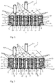
- FIG. 1 shows an exemplary embodiment of a burner 1 which is particularly suitable for the combustion of, while not limited to, hydrogen or hydrogen rich fuels and other, compared to natural gas, highly reactive fuels.
- Burner 1 comprises upstream front wall 11 and downstream front wall 12.
- the combustion air plenum may for a non-limiting instance be arranged to be supplied with compressed air from the compressor of a gas turbine engine, while the combustion space may be arranged to discharge into the expansion turbine of the gas turbine engine.
- air is to be understood as being representative of any oxidation agent, or fluid comprising an oxidation agent, which is suitable for the combustion of a fuel, and said oxidation agent or fluid comprising an oxidation agent is generically disclosed to a skilled person, although for the easy of description air is used as a common example representative of generic oxidation agents or suitable fluids containing oxidation agents.
- a general airflow direction is defined from the upstream wall 11 to downstream wall 12.
- Partition walls 21 and 22 are interposed between upstream front wall 11 and downstream front wall 12 and extend across the general airflow direction.
- Front walls 11 and 12 and partition walls 21 and 22 may generically be referred to as transverse walls, as they extend transverse to or across the general airflow direction of the burner.
- a space between upstream front wall 11 and downstream front wall 12 is divided into three plenums, namely most upstream plenum 31 between upstream front wall 11 and partition wall 21, plenum 32 between partition walls 21 and 22, and most downstream plenum 33 between partition wall 22 and downstream front wall 12.
- Lateral wall 29 may further enclose the plenums.
- Most downstream plenum 33 is preferably used as a coolant plenum in order to cool downstream front wall 12 which is exposed to heat from the combustion space at the downstream side 3 of burner 1.
- Plenum 33 is fed form a coolant supply through coolant feed lines 331, whereby generally coolant bled from the combustion air may be used for cooling purposes. It should be noted that other suitable cooling agents may be used, as will be outlined below.
- coolant plenum 33 is not enclosed by the lateral wall and be placed inside or in fluid communication with a larger air plenum of the combustor, such that cooling air may flow into cooling air plenum 33 form the entire circumference thereof.
- Plenum 31 may be supplied with a fluid through supply terminal 311 which joins into plenum 31 from the upstream side.
- Plenum 32 may be supplied through a fluid supply terminal 321 which extends form the upstream side and through plenum 31.
- the transverse walls 11, 21, 22 and 12 are provided with multiple sets of aligned openings, such that passages 40, of which only some are designated by reference numerals, are formed extending through burner 1 from the upstream side 2 to the downstream side 3.
- Ducts 41 extend through passages 40, through transverse walls 11, 21, 22 and 12 and through the plenums 31, 32, 33.
- the duct walls are provided gas-leak proof with the transverse walls. It should be noted that in embodiments the ducts are seamlessly joined with the transverse walls, in that the ducts and the transverse walls are been manufactured in one monolithic piece. This may in particular be achieved by additive manufacturing.
- Ducts 41 provide fluid communication from the upstream side 2 to the downstream side 3 of the burner along their longitudinal directions. In operation, combustion air flows through ducts 41 from the combustion air plenum of a combustion appliance, or the upstream side, 2 of burner 1, to the combustion space, on the downstream side, 3 of burner 1.
- Through holes 51 are provided through the duct walls and provide fluid communication between plenum 31 and ducts 41.
- Through holes 51 are discharge means for discharging a fluid from plenum 31 into ducts 41.
- Through holes 52 are provided through the duct walls and provide fluid communication between plenum 32 and ducts 41.
- Through holes 52 thus are discharge means for discharging a fluid from plenum 32 into ducts 41. It is noted that in the exemplary embodiment shown all ducts are fluidly connected to all plenums but the coolant plenum 33. However, this is not necessarily the case as will be set forth below.
- hydrogen or a hydrogen rich fuel gas, or any other highly reactive fuel gas may be supplied through plenum 31, and be discharged into the combustion air flow flowing through ducts 41.
- Plenum 32 disposed downstream of plenum 31 may be supplied with water steam or another inert fluid, which is then discharged into the combustion air flow through ducts 41.
- Through holes 52 providing second discharge means may be inclined so as to discharge the steam with a velocity component directed downstream and with a velocity component tangential to the inner surface of the ducts into ducts 41.
- the discharge openings may for instance be configured to discharge the fluid at an angle of less than 45 degrees or less than 30 degrees relative to the longitudinal direction of ducts 41, or the flow of combustion air therethrough, respectively.
- the steam discharged from plenum 32 thus forms a boundary layer adhering to the inner surfaces of the duct walls. It may be found advantageous, when operating the burner in this mode, to avoid discharging fluid downstream of the longitudinal position of the ducts where the inert fluid is discharged. This, however, does not necessarily mean that no plenum having discharge means discharging into the ducts downstream from the inert fluid discharge must be provided. Such plenum, however, would then preferably not be supplied with fluid when inert fluid as a boundary layer is discharged upstream thereof for operation of the burner on a highly reactive fluid. Hence, the inert boundary layer extends to the downstream ends of ducts 41.
- any backflow from the combustion space into the ducts which may occur within the boundary layer will thus be enclosed by inert fluid or even be prevented by the inert fluid boundary layer, rather than getting into contact with a reactive fuel/air mixture, and flashback risk is largely reduced if not avoided.
- most downstream arranged coolant plenum 33 is fluidly isolated from ducts 41 and discharges the coolant though effusion cooling holes 121 in the downstream front wall and into downstream space 3, i.e., into the combustion space, thus effecting cooling of downstream front wall 12.
- the ducts are shown to be slightly divergent at their downstream ends.
- Such flared outlet of the ducts may be useful to reduce exit velocity of the flow from a duct and hence reduce the risk of flame lift-off of the microjet flames so as to ensure a good stabilization of the microjet flames.
- the shape of the ducts at the downstream end might be chosen so as to meet requirements, for instance, as to the velocity of the gas flow emanating from a duct 41 into downstream space 3.
- the upstream end of the duct may be rounded or trumpet-shaped to reduce pressure losses.
- plenums 31 and 32 may be configured, through their connection to different fluid supplies, to be supplied with different fuels such that burner 1 of figure 1 might be used for the alternating or combines combustion of different fuels, for internal piloting of premix combustion, or other operation modes.
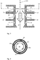
- the device shown in figure 2 differs from the one shown in figure 1 in that not each of plenums 31, 32 is fluidly connected to each duct. It will be appreciated that if a fluid is discharged from plenum 31 through a hole, or discharge means, 51 which is provided further upstream of the downstream end of a duct, wherein said downstream end is provided adjacent downstream front wall 12, or downstream space 3, respectively, mixes more intensely with the flow of combustion air flowing through the respective duct than a fluid discharged into a duct from plenum 32 through more downstream disposed hole, or discharge means, 52.
- both plenums 31 and 32 are configured to be supplied with fuel, for instance natural gas
- fuel supplied from plenum 31 may be considered a premix fuel
- fuel supplied from more downstream plenum 32 may be considered a piloting fuel.
- the piloting fuel combusts in a combustion mode at least more resembling a diffusion combustion mode.
- premix ducts 43 are fluidly connected by relatively upstream disposed discharge means 51 to premix fuel plenum 31
- internally piloted ducts 42 are fluidly connected by relatively upstream discharging discharge means 51 to premix fuel plenum 31 as well as by relatively downstream discharging discharge means 52 to piloting fuel plenum 32.
- holes or discharge means 53 are provided through the walls of internal piloting ducts 42 and are fluidly connecting coolant plenum 33 to internal piloting ducts 42. It could also be conceived to provide such discharge means, fluidly connecting to coolant plenum 33, in premix ducts 43. It might however be assumed that due to the fuel combusting with an at least locally higher equivalence ratio downstream of internal piloting ducts 42, those ducts may be thermally higher loaded than the downstream ends of premix ducts 43, which is accounted for in discharging cooling and dilution air into internal piloting ducts 42 through discharge means 53, while the coolant is saved in premix ducts 43.
- discharge means 51, 52 and 53 are adapted and configured such as to discharge a fluid from inside the respective fluid plenum at different positions along a longitudinal direction of a duct, which also applies with respect to discharge means 51 and 52 of the embodiments of figure 1 .
- coolant plenum 33 it should be noted that generally embodiments are possible in which the coolant is only discharged through discharge means 53 into the ducts, while front wall effusion cooling holes 121 are omitted.
- the premix fuel mass flow and piloting fuel mass flow may be controlled independently from each other by controlling the fuels supply to each of plenums 31 and 32 independently.
- the additional fuel discharged into internal piloting ducts 42 may be accounted for by discharging a lower premix fuel mass flow into internal piloting ducts. This may be achieved in providing discharge means 51 in internal piloting ducts 42 with a smaller overall cross section, for instance, in the given example embodiment, in providing the premix fuel discharge means 51 in internal piloting ducts 42 with smaller and/or less holes compared to premix ducts 43. It is not excluded that all ducts are provided with premix and internal piloting fuel supply.
- a fuel discharge means which is configured to discharge fluid from a plenum into a duct perpendicular to the duct longitudinal direction, i.e. commonly perpendicular to the inner wall of the duct, or with an upstream velocity component relative to the intended combustion air flow direction inside the duct, will result in a more premixed flow at a given distance downstream the discharge location than a fuel discharge means which discharges the fuel with a downstream discharge velocity component relative to the intended combustion air flow direction inside the duct.
- the absolute velocity or impulse of the fluid upon being discharged from the discharge means will have a significant impact on the premixing behaviour, as any person having skill in the art will readily appreciate.
- piloting ducts are provided as dedicated piloting ducts 44 which are in fluid communication only with piloting fuel plenum 32 and coolant plenum 33.
- Figure 4 shows an example embodiment in which plenum 31 is provided as a combined piloting/premix plenum.
- Plenum 31 is fluidly connected by discharge means 51 to premix ducts 43 and is fluidly connected to piloting ducts 44 by discharge means 52.
- Discharge means 52 are arranged closer to the downstream ends of ducts 44 than discharge means 51 relative to the downstream ends of ducts 43. Hence, fluid discharged through discharge means 51 into ducts 43 will be more intensely premixed than fuel discharged through discharge means 52 into ducts 44.
- the embodiment of figure 4 thus enables to provide premix fuel and piloting fuel through one single plenum 31.
- the ratio of the piloting fuel mass flow discharged through discharge means 52 and the premix fuel mass flow discharged through discharge means 51 is, in this embodiment fixed and governed by the number and throughflow cross sections of the discharge means 51 and 52. It is well noted that an embodiment with a combined piloting/premix plenum as shown in figure 4 can also be applied in connection with internal piloting ducts as those labelled 42 in figure 2 . Plenum 32 can, as needed, be used for the supply of any fuel or non-fuel fluid, which, in the non-limiting embodiment of figure 4 , is then discharged through discharge means 54 into all ducts, wherein the supply of fluid to plenum 32 may be controlled independently from the supply of fluid to plenum 31.
- Plenums 31 and 32 may be configured for the supply of other fluids than the exemplarily mentioned natural gas. They may be supplies with different fuel and/or non-fuel fluids.
- the herein disclosed burner is not limited to be provided with three plenums, but more generally may be applied with any number of plenums of two and larger.
- the burner shown in figure 1 may be supplemented with two additional plenums which are merely connected to the premix and piloting ducts like those shown in figures 2 and 3 . It may likewise be supplemented with a combined piloting/premix duct as outlined in figure 4 .
- the same ducts may thus be used for natural gas or, for instance, hydrogen combustion.
- a highly versatile burner which is suitable for instance for the combustion of hydrogen or a hydrogen rich or other highly reactive fuel and for the combustion of natural gas in a variable premix/piloting operation, through the same ducts.
- the order in which the different plenums are arranged along a general airflow direction of the burner from the upstream side defined by upstream front wall 11 to the downstream side defined by downstream from wall 12, or the position along the longitudinal extend of a duct at which fluid from a specific plenum is discharged into the duct, will be determined by the skilled person in applying his general knowledge and taking into account the effect of the mixing distance of a fluid inside the duct from the discharge position of the fluid to the downstream end of the duct.
- elements comprising fluid plenums intended for discharging a specific fluid into at least some of the ducts may be in a virtually modular manner be stacked upon each other. This can be achieved in manufacturing burners with a different number of "slices" comprising a fluid plenum, sections of the ducts, appropriate discharge means for fluidly connecting the plenum to the interior of the ducts, and, optionally, a fluid supply terminal for supplying fluid to the plenum. It might be considered to actually build the burner from stacked upon "slice" members.
- the number of plenums stacked upon each other along the general airflow direction of the burner is in principle not limited; limiting factors might be seen in the increasing length of the ducts and thus increasing pressure losses, and other issues which might arise if fluids are discharged too far upstream of the downstream end of the duct.
- the fluid plenums, with their specific discharge means through which they are fluidly connected to at least one duct, can be stacked in any order a skilled person may find suitable to fulfil a certain purpose. However, it might be found advantageous if the most downstream plenum is a coolant plenum. It will be appreciated that due to the versatility of the herein disclosed burner a comprehensive description of possible embodiments is not practical. However, in understanding the principle behind the stacked micro duct burner herein disclosed and the function and merits of certain specific embodiments of "modules", the skilled person receives a comprehensive teaching.
- module is used within the frame of the present disclosure to denote a “slice” of the burner as defined above, while not stipulating that a module is a standalone member, but may in fact denote a slice of a monolithic member, wherein said slice comprises at least one fluid plenum, sections of the ducts, appropriate discharge means for fluidly connecting the plenum to the interior of the ducts, and, optionally, a fluid supply terminal for supplying fluid to the plenum.
- Fig 5 shows a sectional view of a part of a burner, wherein said part comprises, partially, plenums 35, 36 and 37 and duct 45.
- the plenums are divided from each other by partition walls 25 and 26.
- Duct 45 extends through plenums 35, 36 and 37, and is fluidly connected to plenums 35 and 37 by discharge means 55 and 57, which are provided as holes through the duct walls.
- Plenum 36 is fluidly connected to duct 45 by means of discharge means 561 which is provided as a nozzle essentially suspended inside duct 45 by tubes 156 extending from plenum 36 to discharge means 561 and providing fluid communication between the plenum and the nozzle, or discharge means, respectively.
- the flow of combustion air through duct 45 is represented by arrow 4.
- the nozzle can extend, and provide a discharge position, further downstream than the position of plenum 36, as shown in the exemplary embodiment, but also upstream in the direction of combustion air flow 4 through duct 45.
- nozzle 561 may be provided with through holes at its circumference to discharge the fluid supplied from plenum 36 therethrough.
- nozzle 561 may comprise a discharge opening at at least one of its axial ends.
- nozzle 561 is provided with an atomizer, such as for instance a coaxial plain jet atomizer, at its downstream end.
- At least one duct may be equipped with a discharge means as set forth in connection with figure 5 .
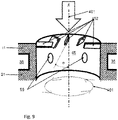
- FIG. 6 outlines an embodiment of a burner 1 in which a cartridge 60 is provided through a passage 40.
- Cartridge 60 may be provided instead of or inside a duct. If cartridge 60 is provided instead of a duct, it is understood that cartridge 60 is preferably configured to achieve a gas-leak proof sealing of plenums 31, 32, 33.
- cartridge 60 extends through a duct, wherein sealing of the plenums is achieved by the duct wall which may be seamless manufactured with front walls 11 and 12 and partition walls 21 and 22 in the primary forming process. Longitudinally extending or spiralling flutes may optionally be provided on an outer surface of the cartridge and/or the inner side of the wall of the duct through which cartridge 60 extends.
- Combustion air may be provided through the flutes.
- the flutes may be spiralling, at least at their downstream ends adjacent downstream front wall 12 and when opening out to the downstream space 3, so as to generate a swirling flow of combustion air at or around the downstream end of cartridge 60.
- An agent 6 may be provided to downstream space 3 through cartridge 60.
- Said agent may be steam, or a gaseous fuel, or mixture of gaseous fuel and other gaseous agent, which may for instance be intended for diffusion combustion.
- the gaseous agent may be discharged with a swirl, which may co- or counter-rotate with a swirl of combustion air.
- cartridge 60 may comprise a liquid agent atomizing nozzle, thus discharging agent 6 as a spray cone 5.
- the liquid may be liquid fuel or water or a mixture thereof.
- a burner of the herein disclosed type may comprise more than one cartridge-As illustrated in figure 7
- discharge means may be arranged and configured to discharge the fluid form a plenum into a duct 45 perpendicular to the longitudinal direction 451, as discharge means 55 of plenum 35, upstream the flow of combustion air 4, or inclined in the upstream direction of duct 45, respectively, as discharge means 56 of plenum 36, or downstream the flow of combustion air 4, or inclined in the downstream direction of duct 45, respectively, as discharge means 57 of plenum 37.
- Figure 8 shows a cross section through an even more particular example of the embodiment shown in figure 7 along line VIII-VIII.
- the discharge means may hence be arranged and configured such that the fluid is discharged from plenum 35 into duct 45 with a tangential velocity component so as to form a vortex flow of discharged fluid as indicated by the circular arrows in figure 8 . It is noted that such a configuration of the discharge means is not limited to the embodiment of figure 7 or any embodiment similar thereto.
- Such configuration suited to generate a vortex flow of fluid discharged from a plenum into a duct may be largely applied, for instance, while not limited to, discharge means discharging the fluid in an upstream or downstream direction of the combustion air flow inside a duct, as for instance depicted at 56 and 57 in figure 7 , or discharge means 561 illustrated in figure 5 .
- At least one duct 45 is provided with a row of vanes 452 disposed inside duct 45 around the circumference of duct 45 and inclined at an angle ⁇ with respect to the longitudinal direction 451 of duct 45 so as to induce a vortex flow as indicated at 401 onto the flow of combustion air 4.
- the vanes may in particular be provided at the upstream end of duct 45 such that the vortex flow of combustion air is present throughout the longitudinal extent of duct 45.
- vanes 452 may be arranged further downstream, so as to discharge fluids from certain plenums into a merely axial flow of combustion air, while others may be discharged into a vortex flow of combustion air.
- the row of vanes 452 may be provided at the downstream end of duct 45. While it should be readily apparent to a person having skill in the art, it should be explicitly mentioned that a vortex flow of combustion air may be combined with a tangential injection of at least one fluid from at least one plenum, as outlined in connection with figure 8 .
- the vortexes of combustion air and of discharged fluid may be co- or counterrotating and may be affected with at least essentially equal tangential velocity components or different tangential velocity components and with essentially identical or different swirl numbers, as found suitable by a person having skill in the art when applying her or his common knowledge.
- the vanes 452 are in particular provided integrally and in one piece, i.e., seamless, with the burner, or the inner wall of a duct, respectively. It will be appreciated that in particular manufacturing the burner with additive manufacturing methods enables providing rather small and complex geometries in one integral workpiece.
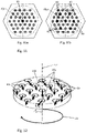
- Figures 10a through 10d show plan views on front faces of burners having different numbers of passages. As can easily be seen, in each burner each three neighbouring passages are provided on the corners of an equilateral triangle. All shown embodiments, irrespective of the number of passages, have in common that a centre passage 40a is concentrically encircled by concentric hexagonal rings of passages. The embodiment of figure 10a exhibits 7 passages, wherein a centre passage 40a is encircled by six passages 40b in a hexagonal arrangement. Each two passages 40b have the same distance from each other than from central passage 40a.
- FIG. 10b exhibits 19 passages, wherein a central passage 40a is encircled by six passages 40b in a first hexagonal ring and 12 passages 40c of a second hexagonal ring.
- the burner can easily be scaled by adding further concentric hexagonal rings of passages, wherein each additional hexagonal ring comprises 6 passages more than the adjacent inner hexagonal ring.
- Each passage, apart from the passages on the outermost hexagonal ring, may in turn be considered to form the centre of another hexagon of surrounding passages. This self-similarity of the arrangement of passages, along with the equidistant arrangement of all neighbouring passages. facilitates scaling of the burner.
- a burner may, on the one hand, be adapted to different burner sizes in adding additional hexagonal rings of passages of the same size and distance from each other.
- a burner of a given size may be provided with different numbers cross-sectional dimensions of the passages, or ducts, respectively.
- FIGs 11a and 11b illustrate possible arrangements of piloting ducts, liquid fuel nozzles, water or steam injection nozzles and so forth in a burner of the described type. It is well understood and goes without saying that said ducts, nozzles and the like extend through passages of the burner.
- a cartridge for atomizing liquid fuel or for the injection of water into a combustion space may be arranged in the central passage 40a.
- Central passage 40a may likewise comprise a piloting duct.
- piloting ducts 44 depicted by filled circles may each be arranged in the centre of a hexagon of premix ducts 43, depicted by empty circles, only some of which are denoted with reference numerals.
- the general teaching is that in aspects of the disclosure passages, or ducts, respectively, which are intended to be provided with means for or are intended to serve, particular purposes may be arranged in the centre of at least one hexagon of "standard" passages.
- Figure 12 illustrates how the passages 40b and 40c of the hexagonal rings, and, consequently, any means provided therethrough, may be inclined relative to a burner axis 101, so as to discharge the flow emanating from said passages, or ducts, respectively with a macroscopic tangential component relative to the burner axis.
- Burner axis 101 is defined at least essentially perpendicular to the downstream front face of the burner.
- the longitudinal direction of central passage 40a, or duct respectively, is in particular aspects at least essentially parallel to burner axis 101, while the longitudinal axis of passages 40b and 40c are inclined about an angle ⁇ relative to the burner axis, so as to generate a vortex flow indicated at 102 downstream the burner, or, more specifically, in the combustion space.
- inclination angle ⁇ of the passages may vary dependent on the distance of a respective passage from central passage 40a. Form one instance, inclination angle ⁇ may increase with increasing distance from central passage 40a. Due to the self-similarity of the arrangement of the passages of one larger burner may be subdivided into smaller areas, wherein each aera defines a local central passage and encircling hexagonal passage arrangement, wherein the passages encircling a specific central passage may be inclined to provide a vortex around said local central passage. An embodiment in which a macroscopic vortex is generated may be found most useful when replacing vortex burners in a legacy combustion appliance.
Landscapes
- Engineering & Computer Science (AREA)
- Chemical & Material Sciences (AREA)
- Combustion & Propulsion (AREA)
- Mechanical Engineering (AREA)
- General Engineering & Computer Science (AREA)
- Gas Burners (AREA)
Priority Applications (14)
| Application Number | Priority Date | Filing Date | Title |
|---|---|---|---|
| EP21151199.3A EP4027059A1 (en) | 2021-01-12 | 2021-01-12 | Burner, combustor, and method for retrofitting a combustion appliance |
| DK22700316.7T DK4278132T3 (da) | 2021-01-12 | 2022-01-07 | Brænder |
| HUE22700316A HUE071337T2 (hu) | 2021-01-12 | 2022-01-07 | Égõfej |
| PCT/EP2022/050242 WO2022152622A1 (en) | 2021-01-12 | 2022-01-07 | Burner |
| CA3204173A CA3204173A1 (en) | 2021-01-12 | 2022-01-07 | Burner |
| EP22700316.7A EP4278132B1 (en) | 2021-01-12 | 2022-01-07 | Burner |
| ES22700316T ES3026507T3 (en) | 2021-01-12 | 2022-01-07 | Burner |
| US18/261,062 US20240060644A1 (en) | 2021-01-12 | 2022-01-07 | Burner |
| LTEPPCT/EP2022/050242T LT4278132T (lt) | 2021-01-12 | 2022-01-07 | Degiklis |
| PT227003167T PT4278132T (pt) | 2021-01-12 | 2022-01-07 | Queimador |
| HRP20250489TT HRP20250489T1 (hr) | 2021-01-12 | 2022-01-07 | Plamenik |
| FIEP22700316.7T FI4278132T3 (fi) | 2021-01-12 | 2022-01-07 | Poltin |
| SI202230120T SI4278132T1 (sl) | 2021-01-12 | 2022-01-07 | Gorilnik |
| PL22700316.7T PL4278132T3 (pl) | 2021-01-12 | 2022-01-07 | Palnik |
Applications Claiming Priority (1)
| Application Number | Priority Date | Filing Date | Title |
|---|---|---|---|
| EP21151199.3A EP4027059A1 (en) | 2021-01-12 | 2021-01-12 | Burner, combustor, and method for retrofitting a combustion appliance |
Publications (1)
| Publication Number | Publication Date |
|---|---|
| EP4027059A1 true EP4027059A1 (en) | 2022-07-13 |
Family
ID=74180944
Family Applications (2)
| Application Number | Title | Priority Date | Filing Date |
|---|---|---|---|
| EP21151199.3A Withdrawn EP4027059A1 (en) | 2021-01-12 | 2021-01-12 | Burner, combustor, and method for retrofitting a combustion appliance |
| EP22700316.7A Active EP4278132B1 (en) | 2021-01-12 | 2022-01-07 | Burner |
Family Applications After (1)
| Application Number | Title | Priority Date | Filing Date |
|---|---|---|---|
| EP22700316.7A Active EP4278132B1 (en) | 2021-01-12 | 2022-01-07 | Burner |
Country Status (13)
| Country | Link |
|---|---|
| US (1) | US20240060644A1 (pl) |
| EP (2) | EP4027059A1 (pl) |
| CA (1) | CA3204173A1 (pl) |
| DK (1) | DK4278132T3 (pl) |
| ES (1) | ES3026507T3 (pl) |
| FI (1) | FI4278132T3 (pl) |
| HR (1) | HRP20250489T1 (pl) |
| HU (1) | HUE071337T2 (pl) |
| LT (1) | LT4278132T (pl) |
| PL (1) | PL4278132T3 (pl) |
| PT (1) | PT4278132T (pl) |
| SI (1) | SI4278132T1 (pl) |
| WO (1) | WO2022152622A1 (pl) |
Cited By (7)
| Publication number | Priority date | Publication date | Assignee | Title |
|---|---|---|---|---|
| EP4212777A1 (en) * | 2022-01-18 | 2023-07-19 | Doosan Enerbility Co., Ltd. | Combustor nozzle |
| WO2023247689A1 (en) | 2022-06-22 | 2023-12-28 | Bdr Thermea Group B.V. | Retrofit kit assembly |
| US11867400B1 (en) * | 2023-02-02 | 2024-01-09 | Pratt & Whitney Canada Corp. | Combustor with fuel plenum with mixing passages having baffles |
| EP4317778A1 (en) * | 2022-08-01 | 2024-02-07 | BDR Thermea Group B.V. | Retrofit kit assembly |
| EP4317777A1 (en) * | 2022-08-01 | 2024-02-07 | BDR Thermea Group B.V. | Retrofit kit assembly |
| EP4317780A1 (en) * | 2022-08-01 | 2024-02-07 | BDR Thermea Group B.V. | Retrofit kit assembly |
| EP4317779A1 (en) * | 2022-08-01 | 2024-02-07 | BDR Thermea Group B.V. | Retrofit kit assembly |
Families Citing this family (3)
| Publication number | Priority date | Publication date | Assignee | Title |
|---|---|---|---|---|
| US12215867B2 (en) | 2023-01-06 | 2025-02-04 | Ge Infrastructure Technology Llc | Gas turbine combustor with dynamics mitigation system |
| US12379108B2 (en) | 2023-01-06 | 2025-08-05 | Ge Vernova Infrastructure Technology Llc | Method of operating gas turbine combustor with multiple fuel stages |
| US12601490B2 (en) * | 2024-05-09 | 2026-04-14 | Ge Infrastructure Technology Llc | Axial fuel stage injector with multiple mixing chambers, and combustor and GT system including same |
Citations (12)
| Publication number | Priority date | Publication date | Assignee | Title |
|---|---|---|---|---|
| US4100733A (en) | 1976-10-04 | 1978-07-18 | United Technologies Corporation | Premix combustor |
| US4455840A (en) * | 1981-03-04 | 1984-06-26 | Bbc Brown, Boveri & Company, Limited | Ring combustion chamber with ring burner for gas turbines |
| US6267585B1 (en) | 1995-12-19 | 2001-07-31 | Daimlerchrysler Aerospace Airbus Gmbh | Method and combustor for combusting hydrogen |
| US20100218501A1 (en) | 2009-02-27 | 2010-09-02 | General Electric Company | Premixed direct injection disk |
| US20120137694A1 (en) * | 2007-11-29 | 2012-06-07 | Hitachi, Ltd. | Burner and gas turbine combustor |
| US20130074510A1 (en) * | 2011-09-25 | 2013-03-28 | General Electric Company | Combustor and method for supplying fuel to a combustor |
| US8438851B1 (en) * | 2012-01-03 | 2013-05-14 | General Electric Company | Combustor assembly for use in a turbine engine and methods of assembling same |
| US20130232979A1 (en) | 2012-03-12 | 2013-09-12 | General Electric Company | System for enhancing mixing in a multi-tube fuel nozzle |
| US20150076251A1 (en) | 2013-09-19 | 2015-03-19 | General Electric Company | System for injecting fuel in a gas turbine combustor |
| WO2015182154A1 (en) | 2014-05-30 | 2015-12-03 | Kawasaki Jukogyo Kabushiki Kaisha | Combustor for gas turbine engine |
| US20160033133A1 (en) | 2014-07-31 | 2016-02-04 | General Electric Company | Combustor nozzles in gas turbine engines |
| DE112018002222T5 (de) * | 2017-04-28 | 2020-02-20 | Mitsubishi Hitachi Power Systems, Ltd. | Brennstoffinjektor und Gasturbine |
Family Cites Families (12)
| Publication number | Priority date | Publication date | Assignee | Title |
|---|---|---|---|---|
| DE2950535A1 (de) * | 1979-11-23 | 1981-06-11 | BBC AG Brown, Boveri & Cie., Baden, Aargau | Brennkammer einer gasturbine mit vormisch/vorverdampf-elementen |
| US7416571B2 (en) * | 2005-03-09 | 2008-08-26 | Conocophillips Company | Compact mixer for the mixing of gaseous hydrocarbon and gaseous oxidants |
| US8276385B2 (en) * | 2009-10-08 | 2012-10-02 | General Electric Company | Staged multi-tube premixing injector |
| US8800289B2 (en) * | 2010-09-08 | 2014-08-12 | General Electric Company | Apparatus and method for mixing fuel in a gas turbine nozzle |
| US9004912B2 (en) * | 2011-11-11 | 2015-04-14 | General Electric Company | Combustor and method for supplying fuel to a combustor |
| US9677766B2 (en) * | 2012-11-28 | 2017-06-13 | General Electric Company | Fuel nozzle for use in a turbine engine and method of assembly |
| US9435540B2 (en) * | 2013-12-11 | 2016-09-06 | General Electric Company | Fuel injector with premix pilot nozzle |
| DE102015003920A1 (de) * | 2014-09-25 | 2016-03-31 | Dürr Systems GmbH | Brennerkopf eines Brenners und Gasturbine mit einem solchen Brenner |
| US10309653B2 (en) * | 2016-03-04 | 2019-06-04 | General Electric Company | Bundled tube fuel nozzle with internal cooling |
| US10295190B2 (en) * | 2016-11-04 | 2019-05-21 | General Electric Company | Centerbody injector mini mixer fuel nozzle assembly |
| EP3425281B1 (en) * | 2017-07-04 | 2020-09-02 | General Electric Company | Pilot nozzle with inline premixing |
| US11156360B2 (en) * | 2019-02-18 | 2021-10-26 | General Electric Company | Fuel nozzle assembly |
-
2021
- 2021-01-12 EP EP21151199.3A patent/EP4027059A1/en not_active Withdrawn
-
2022
- 2022-01-07 CA CA3204173A patent/CA3204173A1/en active Pending
- 2022-01-07 ES ES22700316T patent/ES3026507T3/es active Active
- 2022-01-07 SI SI202230120T patent/SI4278132T1/sl unknown
- 2022-01-07 PT PT227003167T patent/PT4278132T/pt unknown
- 2022-01-07 HR HRP20250489TT patent/HRP20250489T1/hr unknown
- 2022-01-07 WO PCT/EP2022/050242 patent/WO2022152622A1/en not_active Ceased
- 2022-01-07 LT LTEPPCT/EP2022/050242T patent/LT4278132T/lt unknown
- 2022-01-07 FI FIEP22700316.7T patent/FI4278132T3/fi active
- 2022-01-07 PL PL22700316.7T patent/PL4278132T3/pl unknown
- 2022-01-07 US US18/261,062 patent/US20240060644A1/en active Pending
- 2022-01-07 DK DK22700316.7T patent/DK4278132T3/da active
- 2022-01-07 HU HUE22700316A patent/HUE071337T2/hu unknown
- 2022-01-07 EP EP22700316.7A patent/EP4278132B1/en active Active
Patent Citations (12)
| Publication number | Priority date | Publication date | Assignee | Title |
|---|---|---|---|---|
| US4100733A (en) | 1976-10-04 | 1978-07-18 | United Technologies Corporation | Premix combustor |
| US4455840A (en) * | 1981-03-04 | 1984-06-26 | Bbc Brown, Boveri & Company, Limited | Ring combustion chamber with ring burner for gas turbines |
| US6267585B1 (en) | 1995-12-19 | 2001-07-31 | Daimlerchrysler Aerospace Airbus Gmbh | Method and combustor for combusting hydrogen |
| US20120137694A1 (en) * | 2007-11-29 | 2012-06-07 | Hitachi, Ltd. | Burner and gas turbine combustor |
| US20100218501A1 (en) | 2009-02-27 | 2010-09-02 | General Electric Company | Premixed direct injection disk |
| US20130074510A1 (en) * | 2011-09-25 | 2013-03-28 | General Electric Company | Combustor and method for supplying fuel to a combustor |
| US8438851B1 (en) * | 2012-01-03 | 2013-05-14 | General Electric Company | Combustor assembly for use in a turbine engine and methods of assembling same |
| US20130232979A1 (en) | 2012-03-12 | 2013-09-12 | General Electric Company | System for enhancing mixing in a multi-tube fuel nozzle |
| US20150076251A1 (en) | 2013-09-19 | 2015-03-19 | General Electric Company | System for injecting fuel in a gas turbine combustor |
| WO2015182154A1 (en) | 2014-05-30 | 2015-12-03 | Kawasaki Jukogyo Kabushiki Kaisha | Combustor for gas turbine engine |
| US20160033133A1 (en) | 2014-07-31 | 2016-02-04 | General Electric Company | Combustor nozzles in gas turbine engines |
| DE112018002222T5 (de) * | 2017-04-28 | 2020-02-20 | Mitsubishi Hitachi Power Systems, Ltd. | Brennstoffinjektor und Gasturbine |
Cited By (10)
| Publication number | Priority date | Publication date | Assignee | Title |
|---|---|---|---|---|
| EP4212777A1 (en) * | 2022-01-18 | 2023-07-19 | Doosan Enerbility Co., Ltd. | Combustor nozzle |
| WO2023247689A1 (en) | 2022-06-22 | 2023-12-28 | Bdr Thermea Group B.V. | Retrofit kit assembly |
| WO2023247692A1 (en) | 2022-06-22 | 2023-12-28 | Bdr Thermea Group B.V. | Retrofit kit assembly |
| WO2023247690A1 (en) | 2022-06-22 | 2023-12-28 | Bdr Thermea Group B.V. | Retrofit kit assembly |
| WO2023247691A1 (en) | 2022-06-22 | 2023-12-28 | Bdr Thermea Group B.V. | Retrofit kit assembly |
| EP4317778A1 (en) * | 2022-08-01 | 2024-02-07 | BDR Thermea Group B.V. | Retrofit kit assembly |
| EP4317777A1 (en) * | 2022-08-01 | 2024-02-07 | BDR Thermea Group B.V. | Retrofit kit assembly |
| EP4317780A1 (en) * | 2022-08-01 | 2024-02-07 | BDR Thermea Group B.V. | Retrofit kit assembly |
| EP4317779A1 (en) * | 2022-08-01 | 2024-02-07 | BDR Thermea Group B.V. | Retrofit kit assembly |
| US11867400B1 (en) * | 2023-02-02 | 2024-01-09 | Pratt & Whitney Canada Corp. | Combustor with fuel plenum with mixing passages having baffles |
Also Published As
| Publication number | Publication date |
|---|---|
| FI4278132T3 (fi) | 2025-05-20 |
| EP4278132A1 (en) | 2023-11-22 |
| PL4278132T3 (pl) | 2025-07-07 |
| SI4278132T1 (sl) | 2025-06-30 |
| CA3204173A1 (en) | 2022-07-21 |
| EP4278132B1 (en) | 2025-03-05 |
| PT4278132T (pt) | 2025-05-06 |
| HRP20250489T1 (hr) | 2025-06-20 |
| LT4278132T (lt) | 2025-05-12 |
| HUE071337T2 (hu) | 2025-08-28 |
| DK4278132T3 (da) | 2025-05-19 |
| ES3026507T3 (en) | 2025-06-11 |
| US20240060644A1 (en) | 2024-02-22 |
| WO2022152622A1 (en) | 2022-07-21 |
Similar Documents
| Publication | Publication Date | Title |
|---|---|---|
| EP4027059A1 (en) | Burner, combustor, and method for retrofitting a combustion appliance | |
| EP2065645B1 (en) | Burner and gas turbine combustor | |
| US7870736B2 (en) | Premixing injector for gas turbine engines | |
| US8464537B2 (en) | Fuel nozzle for combustor | |
| JP5103454B2 (ja) | 燃焼器 | |
| US9366441B2 (en) | Burner, combustor and remodeling method for burner | |
| CN103388838B (zh) | 具有带有差异化流的多管燃料喷嘴的系统和方法 | |
| EP2163819B1 (en) | Gas turbine combustor | |
| RU2611551C2 (ru) | Топка (варианты) и способ распределения топлива в топке | |
| JP4922878B2 (ja) | ガスタービン燃焼器 | |
| US20120031097A1 (en) | Multi-premixer fuel nozzle | |
| JP2013504733A (ja) | 燃焼装置用の入口予混合器 | |
| CN102927592A (zh) | 涡轮机燃烧器组件 | |
| JP2010096487A (ja) | 燃焼器バーナのベーンレット | |
| CN102345879A (zh) | 燃料喷嘴及包括该燃料喷嘴的组件和燃气涡轮机 | |
| JP2011064447A (ja) | 燃焼器用の半径方向入口案内翼 | |
| CN115451432B (zh) | 一种燃气轮机燃烧室燃料的微混喷嘴组件及系统 | |
| US8881531B2 (en) | Gas turbine engine premix injectors | |
| EP1531305A1 (en) | Multi-point fuel injector | |
| JP5331909B2 (ja) | 燃焼器 | |
| EP3376110B1 (en) | Gas turbine electrical power plant and method for operating said gas turbine electrical power plant | |
| HK1176388B (en) | Inlet premixer for combustion apparatus | |
| HK1176989B (en) | Vortex premixer for combustion apparatus | |
| HK1176663B (en) | Combustion cavity layouts for fuel staging in trapped vortex combustors | |
| HK1176664B (en) | Method of fuel staging in combustion apparatus |
Legal Events
| Date | Code | Title | Description |
|---|---|---|---|
| PUAI | Public reference made under article 153(3) epc to a published international application that has entered the european phase |
Free format text: ORIGINAL CODE: 0009012 |
|
| STAA | Information on the status of an ep patent application or granted ep patent |
Free format text: STATUS: THE APPLICATION HAS BEEN PUBLISHED |
|
| AK | Designated contracting states |
Kind code of ref document: A1 Designated state(s): AL AT BE BG CH CY CZ DE DK EE ES FI FR GB GR HR HU IE IS IT LI LT LU LV MC MK MT NL NO PL PT RO RS SE SI SK SM TR |
|
| STAA | Information on the status of an ep patent application or granted ep patent |
Free format text: STATUS: THE APPLICATION IS DEEMED TO BE WITHDRAWN |
|
| 18D | Application deemed to be withdrawn |
Effective date: 20230114 |