EP4027138A1 - Verbessertes verfahren und system zur überwachung von generativer fertigung - Google Patents
Verbessertes verfahren und system zur überwachung von generativer fertigung Download PDFInfo
- Publication number
- EP4027138A1 EP4027138A1 EP21150518.5A EP21150518A EP4027138A1 EP 4027138 A1 EP4027138 A1 EP 4027138A1 EP 21150518 A EP21150518 A EP 21150518A EP 4027138 A1 EP4027138 A1 EP 4027138A1
- Authority
- EP
- European Patent Office
- Prior art keywords
- eigenfrequency
- solid
- vibrational
- solid piece
- mode
- Prior art date
- Legal status (The legal status is an assumption and is not a legal conclusion. Google has not performed a legal analysis and makes no representation as to the accuracy of the status listed.)
- Withdrawn
Links
Images



Classifications
-
- G—PHYSICS
- G01—MEASURING; TESTING
- G01N—INVESTIGATING OR ANALYSING MATERIALS BY DETERMINING THEIR CHEMICAL OR PHYSICAL PROPERTIES
- G01N29/00—Investigating or analysing materials by the use of ultrasonic, sonic or infrasonic waves; Visualisation of the interior of objects by transmitting ultrasonic or sonic waves through the object
- G01N29/04—Analysing solids
- G01N29/045—Analysing solids by imparting shocks to the workpiece and detecting the vibrations or the acoustic waves caused by the shocks
-
- B—PERFORMING OPERATIONS; TRANSPORTING
- B29—WORKING OF PLASTICS; WORKING OF SUBSTANCES IN A PLASTIC STATE IN GENERAL
- B29C—SHAPING OR JOINING OF PLASTICS; SHAPING OF MATERIAL IN A PLASTIC STATE, NOT OTHERWISE PROVIDED FOR; AFTER-TREATMENT OF THE SHAPED PRODUCTS, e.g. REPAIRING
- B29C64/00—Additive manufacturing, i.e. manufacturing of three-dimensional [3D] objects by additive deposition, additive agglomeration or additive layering, e.g. by 3D printing, stereolithography or selective laser sintering
- B29C64/30—Auxiliary operations or equipment
- B29C64/386—Data acquisition or data processing for additive manufacturing
- B29C64/393—Data acquisition or data processing for additive manufacturing for controlling or regulating additive manufacturing processes
-
- G—PHYSICS
- G01—MEASURING; TESTING
- G01N—INVESTIGATING OR ANALYSING MATERIALS BY DETERMINING THEIR CHEMICAL OR PHYSICAL PROPERTIES
- G01N29/00—Investigating or analysing materials by the use of ultrasonic, sonic or infrasonic waves; Visualisation of the interior of objects by transmitting ultrasonic or sonic waves through the object
- G01N29/04—Analysing solids
- G01N29/12—Analysing solids by measuring frequency or resonance of acoustic waves
-
- B—PERFORMING OPERATIONS; TRANSPORTING
- B33—ADDITIVE MANUFACTURING TECHNOLOGY
- B33Y—ADDITIVE MANUFACTURING, i.e. MANUFACTURING OF THREE-DIMENSIONAL [3D] OBJECTS BY ADDITIVE DEPOSITION, ADDITIVE AGGLOMERATION OR ADDITIVE LAYERING, e.g. BY 3D PRINTING, STEREOLITHOGRAPHY OR SELECTIVE LASER SINTERING
- B33Y50/00—Data acquisition or data processing for additive manufacturing
- B33Y50/02—Data acquisition or data processing for additive manufacturing for controlling or regulating additive manufacturing processes
-
- G—PHYSICS
- G01—MEASURING; TESTING
- G01N—INVESTIGATING OR ANALYSING MATERIALS BY DETERMINING THEIR CHEMICAL OR PHYSICAL PROPERTIES
- G01N2291/00—Indexing codes associated with group G01N29/00
- G01N2291/01—Indexing codes associated with the measuring variable
- G01N2291/014—Resonance or resonant frequency
-
- G—PHYSICS
- G01—MEASURING; TESTING
- G01N—INVESTIGATING OR ANALYSING MATERIALS BY DETERMINING THEIR CHEMICAL OR PHYSICAL PROPERTIES
- G01N2291/00—Indexing codes associated with group G01N29/00
- G01N2291/02—Indexing codes associated with the analysed material
- G01N2291/023—Solids
- G01N2291/0231—Composite or layered materials
-
- G—PHYSICS
- G01—MEASURING; TESTING
- G01N—INVESTIGATING OR ANALYSING MATERIALS BY DETERMINING THEIR CHEMICAL OR PHYSICAL PROPERTIES
- G01N2291/00—Indexing codes associated with group G01N29/00
- G01N2291/02—Indexing codes associated with the analysed material
- G01N2291/028—Material parameters
- G01N2291/0289—Internal structure, e.g. defects, grain size, texture
Definitions
- the present invention relates to a non-destructive method for monitoring an additive manufacturing process with respect to porosity, sinter quality, elasticity, microcellular clustering, defects, etc. Hereby deviating process behaviour can be timely observed and optionally corrected.
- the present invention also relates to a method for calibrating an additive manufacturing apparatus, e.g. by compensation of the deviating process behaviour.
- additive manufacturing also called three-dimensional or 3D printing
- additive manufacturing is a process which has gained a lot of momentum in recent years. It allows construction of a three-dimensional object from a CAD model or a digital 3D model.
- material can be deposited, joined or solidified under control conditions to create a three-dimensional object, with material being added together, such as liquid molecules or powder grains being fused together, typically layer by layer.
- the precision, repeatability, and material range of 3D printing have increased to the point that some 3D printing processes are considered viable as an industrial-production technology.
- One of the key advantages of 3D printing is the ability to produce very complex shapes or geometries that would be otherwise impossible to construct by hand, including hollow parts or parts with internal truss structures to reduce weight.
- AM process involves incremental deposition of material, it gives unique opportunities to monitor the material quality as it is deposited. To meet this need there are a variety of sensing methods and signals which can be measured. Among the available measurement modalities, acoustic-based methods have the advantage of potentially providing real-time, continuous in-service monitoring of manufacturing processes at relatively low cost.
- the present invention aims to overcome the above mentioned and other problems.
- the present invention hereto provides a method for monitoring an additive manufacturing process which is easier to use and/or implement than prior art methods and which allows precise measurements of deviating AM process behaviour on the basis of acoustic measurements.
- the present invention concerns a method for non-destructively detecting deviating additive manufacturing (AM) process behaviour of a 3D printed solid piece, comprising the steps of:
- the present invention also concerns a system for non-destructively detecting deviating additive manufacturing (AM) process behaviour of a 3D printed solid piece, comprising:
- Patent application EP 3 435 044 A1 discloses an apparatus for analyzing a mechanical vibratory response of a solid material sample, the apparatus comprising: at least one impactor arranged to impart an impact on respective well-defined points on the surface of said solid material sample; a sensor configured to capture said mechanical vibratory response as a time-varying signal, subsequent to an impact of said at least one impactor; and processing means configured to analyze said time-varying signal to determine the frequencies and decay constants of sinusoids making up said time-varying signal.
- the invention also pertains to a corresponding method of characterizing a solid material sample. The method and apparatus described in this document can be used to perform the measurement of the vibrational response of the solid piece to the impact.
- the present invention concerns a method for calibrating a 3D printing apparatus, comprising the steps of:
- the present invention also relates to a 3D printing steering method, comprising performing the calibration method on a set of at least one solid piece at multiple measurement events during forming of the solid piece, whereby the reference eigenfrequency value at each measurement event is a predefined target reference eigenfrequency for said measurement event, and whereby processing parameters of the 3D printing apparatus are steered on the basis of the eigenfrequency shift.
- the vibrational response is obtained by an acoustic sensor.
- the acoustic sensor may be in contact with the solid piece or may be positioned at a distance from the solid piece.
- the acoustic sensor is positioned at a distance from the solid piece. This allows in-situ and in-process monitoring without having the difficulty of ensuring that the acoustic sensor is in contact with the solid piece under construction.
- the method is applied in-situ.
- the method is applied during the additive manufacturing process. This allows in-situ monitoring of the AM process in real time, which can help in identifying during which parts of the AM process the deviating behaviour occurs. If the AM process comprises printing the solid piece layer by layer, the in-situ monitoring also allows locating where a defect may occur in the solid piece. It also may allow steering the AM process.
- the present invention relates to a method and system for non-destructively detecting deviating additive manufacturing (AM) process behaviour of a 3D printed solid piece as specified before and in the claims and which is further specified in this document.
- AM additive manufacturing
- the detection method comprises the steps of providing an impact to the solid piece, preferably a mechanical impact; obtaining a vibrational response of the solid piece to the impact in the frequency domain; extracting a set of eigenfrequencies, and optionally attenuations, from the vibrational response, each of said eigenfrequencies corresponding to a vibrational mode of said solid piece; and obtaining for at least one vibrational mode: an eigenfrequency shift by comparing one of the set of extracted eigenfrequencies corresponding to said vibrational mode to a reference eigenfrequency value of said vibrational mode, thereby detecting the deviating AM process behaviour.
- the eigenfrequency shift refers to a change of an eigenfrequency peak in the response as observed in the frequency domain.
- This change can be a difference in the peak frequency of a vibrational mode between the extracted eigenfrequency and the reference eigenfrequency, but can also refer to a change in the peak width.
- the eigenfrequency shift can for instance be quantified by looking at the change of frequencies at half the peak height. A widened peak tends to indicate increased dampening due to increased internal friction, which could be caused by microcracks.
- the system for obtaining the response may comprise an apparatus for analyzing a mechanical vibratory response of a solid material sample, an embodiment of which is schematically illustrated in Figure 1 .
- This embodiment can be used to test 3D solid pieces by placing the solid piece on the sample holder.
- the apparatus 100 comprises at least one impactor (i.e., one or more impactors) 110 arranged to impart an impact on respective well-defined points on the surface of the solid material sample 99. Without loss of generality, an apparatus 100 with a single impactor 110 is illustrated.
- the apparatus 100 further comprises a sensor 120 configured to capture the mechanical vibratory response of the sample 99 as a time-varying signal, subsequent to an impact of the at least one impactor 99.
- a suitable sample holder 199 for example comprising linear supports, is provided to allow the sample 99 to freely vibrate upon impact.
- the apparatus 100 further comprises processing means 130 configured to analyze the time-varying signal to determine the frequencies and decay constants of sinusoids making up the time-varying signal.
- the impactors 110 may comprise one or more hammers that are preferably attached to the rest of the apparatus and automatically operated (i.e., weights mounted on an actuated, optionally springloaded arm) or other projectiles.
- the sensor 120 may comprise a contact-based sensor such as a piezoelectric sensor, a noncontact-based sensor such as a microphone or a laser vibrometer, or an accelerometer.
- a contact-based sensor such as a piezoelectric sensor, but also with a microphone, laser vibrometer or accelerometer.
- the piezoelectric sensor may be arranged in a probe that may further include a signal amplifier, means to illuminate a spot where the mechanical vibratory response is captured (e.g., a small laser source arranged to illuminate the anticipated point of contact with a spot of light as the probe is brought towards the surface of the sample), and/or a temperature sensor.
- the probe is preferably equipped with means to measure the force applied by the sensor on the sample.
- the apparatus may include means to automatically bring the probe in contact with the sample, such as an actuated arm or a more complex robotic support.
- the force measuring means provide the necessary feedback to ensure a good contact between the sensor and the sample.
- the apparatus may be configured to provide visual and/or auditory feedback to help the user keep the contact force within a predetermined target range (for example, an LED may be made to light up in one color when the applied force is too high, and in another color when it is too low; an intermittent beeping sound may have a different pitch or period depending on whether the applied force is too high or too low; etc.).
- a predetermined target range for example, an LED may be made to light up in one color when the applied force is too high, and in another color when it is too low; an intermittent beeping sound may have a different pitch or period depending on whether the applied force is too high or too low; etc.
- the apparatus comprises more than one impactor, these may be arranged for example as a linear array or as a rectangular grid.
- the apparatus may act as a scanner, moving the sample under the line of impactors for consecutive tests on different parts of the sample, or moving the line of impactors across the sample for consecutive tests on different parts of the sample.
- the apparatus is preferably equipped with precisely controllable motors to provide the required relative movement of the sample and the impactors. Where the impactors are arranged as a grid, such relative movement will only be necessary if the extent of the grid does not cover the entire area of interest of the sample.
- the apparatus preferably comprises means to determine geometric properties of the solid material sample (not illustrated), such as a 3D scanner, a camera (optionally stereoscopic), or the like.
- the apparatus 100 may comprise a conventional user interface, which may include a screen 140 (preferably a touch-screen), buttons or dials 150, a keypad (not illustrated), and the like.
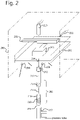
- FIG. 2 a preferred embodiment of an apparatus for analyzing a mechanical vibratory response of a solid material sample is illustrated in figure 2 .
- the apparatus can be positioned in and around a 3D printing chamber (200) with a printing head (201).
- the apparatus comprises a printing plate (202) onto which one or more solid pieces (203) may be additionally manufactured.
- the printing plate (202) is suspended by a support structure (204, 205) which allows the test piece to vibrate as freely as possible, e.g. by supporting at the location of vibrational nodes of the test piece.
- An acoustic sensor (210,211), or multiple acoustic sensors (210,211), which may comprise a microphone or a laser-interferometer, can be placed within the 3D printing chamber to obtain the vibrational response of the solid piece to an impact.
- the acoustic sensor comprises a laser interferometer.
- a laser interferometer is particularly useful for measurements in vacuum, and allows contactless measurements.
- the acoustic sensor may comprise an ultrasonic measurement sensor and/or a time-of-flight sensor and/or a Doppler-based sensor, for instance as described in:
- these types of sensor may be used for contactless measurements.
- the method of the present invention is performed whereby the 3D printing chamber comprises a pressure which is lower than the atmospheric pressure, preferably 0.5 bar or less, more preferably 0.2 bar or less, most preferably essentially a vacuum pressure.
- a laser interferometer is used to allow contactless vibrational measurement at low to zero pressure. Measurements at reduced to zero pressure dampen surrounding noises, thereby increasing the signal-to-noise ratio.
- the apparatus preferably comprises an impact system, which comprises a ballistic impactor (212) which can be provided with an impulse by an impactor actuator (213).
- the ballistic impactor (212) can be a ceramic rod or metal rod. It can be shot upwards (214) towards the test piece using the impactor actuator (213), which comprises:
- the impactor actuator is arranged to provide an impulse to the ballistic impactor.
- a noise measuring step is performed, whereby the ballistic impactor is brought up to within 2 cm below the printing plate or solid piece, but without touching the printing plate or solid piece.
- the impactor actuator is then preferably arranged to provide an impulse to the ballistic impactor which brings it into contact with the printing plate or solid piece and thereby mechanically induces a vibrational excitation to the printing plate and/or solid piece.
- the vibrational response of the solid piece is a time-varying signal which can be obtained via a vibrational sensor.
- the vibrational response can then be further analyzed.
- the system of the present invention preferably comprises a processing means which is configured to analyze the time-varying signal to determine the frequencies and decay constants of sinusoids making up the time-varying signal, i.e. it solves a harmonic inversion problem.
- the problem of a harmonic inversion which more generally consists of determining frequencies, decay constants, amplitudes, and phases of the sinusoids making up a discrete-time, finite-length signal that consists of a sum of a finite number of such sinusoids in a given bandwidth, is well known in literature, but is rarely associated with impulse excitation techniques (IET). Vladimir A.
- the processing means may consist of one or more dedicated hardware components (e.g. ASIC), appropriately configured configurable hardware components (e.g. FPGA), microprocessors provided with suitable software, or a combination of the above. The same components may also perform other functions.
- a vibrational response of the solid piece to the impact in the frequency domain can be obtained.
- a set of eigenfrequencies, and optionally attenuations can be extracted, each of said eigenfrequencies corresponding to a vibrational mode of said solid piece.
- an eigenfrequency shift can be obtained by comparing one of the set of extracted eigenfrequencies corresponding to said vibrational mode to a reference eigenfrequency value of said vibrational mode, thereby detecting the deviating AM process behaviour.
- an eigenfrequency shift may comprise a change in the width of the peak in the response, which e.g. could be quantified by looking at the change of frequencies at half the peak height.
- the reference eigenfrequency value is obtained from a database.
- This database may preferably be obtained by measured eigenfrequencies on solid pieces of various shapes and sizes and of the same material as the solid piece which is additively manufactured.
- the reference eigenfrequency value can then be obtained via direct comparison with a value from the database related to a solid piece of the same shape, size and material, or via an interpolation value obtained on the basis of values from the database.
- the reference eigenfrequency may be obtained from an eigenfrequency trajectory. This eigenfrequency trajectory may preferably describe the eigenfrequency of a solid piece with a determined cross section, in function of the height of the solid piece.
- the height hereby refers to a size of the solid piece as measured in a direction perpendicular to the cross section.
- the solid piece may have a rectangular cross section of width w and length I, and the eigenfrequency trajectory then describes the dependence of the eigenfrequency of the solid piece on the height thereof.
- the eigenfrequency trajectory may be obtained from calibration measurements.
- the eigenfrequency trajectory can be determined via a set of eigenfrequency measurements performed at different moments during a calibration AM process of a calibration piece, which is essentially the same as the solid piece, i.e. it is made from the same material, with the same size and shape.
- the quality of the calibration piece can be checked thoroughly, and if approved, the eigenfrequency measurements obtained during the production of the calibration piece, can be used to construct the eigenvalue trajectory.
- the eigenvalue trajectory can be constructed in function of one or more characteristics of the calibration piece and/or the calibration AM process. Preferably these characteristics comprise any or any combination of the following:
- an eigenfrequency value obtained for the solid piece during the AM process can be compared with an eigenfrequency value on the eigenfrequency trajectory at the corresponding characteristics. For instance, if the AM process for the solid piece follows the same procedure as the AM process for the calibration piece, the eigenfrequency value obtained for the solid piece at time T needs to be compared with the reference eigenfrequency value obtained from the eigenfrequency trajectory at the same time T. If the AM process for the solid piece does not follow the same procedure as the AM process of the calibration piece, the characteristics preferably comprise one or more sizes. In this case, the eigenfrequency value obtained for the solid piece when it has a particular size can be compared with the eigenfrequency trajectory for that particular size.
- figs. 3a and 3b This embodiment is illustrated in figs. 3a and 3b .
- a solid piece (301) is being 3D printed on a printing plate (302).
- a number of frequency measurement using an impact excitation technique are performed at regular intervals, corresponding to certain heights (303) for the 3D printed piece (301).
- the results can be illustrated by fig. 3b , where we show a reference eigenfrequency trajectory (304) in function of the height (306) of the solid piece being printed, as well as the measured eigenfrequencies (305) in function of said height (306).
- a deviation between the eigenfrequency values, i.e. an observed eigenfrequency shift (308) indicates deviating process behaviour at a specific height. Note that it is possible that at full height (309), the frequency shift may vanish, even if the shift was present at intermediate height, indicating the importance of performing many measurements at different heights for a full monitoring.
- the eigenvalue trajectory can be based on the database as described above, or on measured eigenfrequencies on solid pieces of various shapes and sizes and of the same material as the solid piece which is additively manufactured.
- Embodiments wherein the reference eigenfrequency value is at least partially obtained from an eigenfrequency trajectory are particularly apt in observing deviating AM process behaviour, in particular in-situ and/or in real time.
- the reference eigenfrequency value may be obtained by a numerical computation and/or simulation. Note that such computation and simulation may be combined with measurements of the eigenfrequency values of solid pieces or of calibration pieces, in order to obtain the best reference eigenfrequency value.
- the deviating process behaviour which is detected is related to a badly sintered portion of the solid piece. Badly sintered portions lead to changes in vibrational parameters.
- a bad sintering process has a large effect of the stiffness of the solid piece, typically a reduction of stiffness, which can be observed in the different material parameters, such a moduli (Young's modulus, shear moduli, ...) and damping coefficients. These material parameters are closely connected to the acoustic response of a piece to mechanical impact. Hence, the present invention is particularly apt in detecting bad or incomplete sintering of a 3D printed solid piece.
- the extracted eigenfrequencies correspond to vibrational modes of the solid piece.
- the vibrational modes can be any mode giving information on the distributed mechanic elastic behaviour of the solid piece.
- the vibrational modes may comprise any or any combination of a flexional mode, a torsional mode, a longitudinal vibration mode, or any harmonics thereof, such as the 1 st , 2 nd , 3 rd harmonic, more preferably the 1 st harmonic of the flexional mode, the 2 nd harmonic of the flexional mode, the 1 st harmonic of the torsional mode, the 2 nd harmonic of the torsional mode, the 1 st harmonic of the longitudinal vibrational mode.
- the vibrational modes comprise a torsional mode and/or any harmonics thereof.
- the deviating process behaviour is detected by obtaining one or more eigenfrequency shifts and/or by taking into account a peak width in the extracted vibrational response.
- the present invention also relates to a calibration method, comprising the following steps:
- the solid pieces which are used to obtain positional information are also referred to as calibration pieces.
- the set of solid pieces may be arranged in a predefined pattern, preferably a matrix pattern, with respect to the printing plate. This allows obtaining positional information of the deviating process behaviour in the X-Y position of the printing plate. This is preferably done by identifying in which solid piece the deviating process behaviour occurs. There are a number of ways this identification can be done:
- the predefined pattern may preferably be a rectangular matrix pattern in a x-y plane which is preferably a horizontal plane.
- a set of solid pieces (401,402,403,404,406) is being 3D printed on a printing plate (405).
- four of these solid pieces (401,402,403,404) are being printed at the corners of the printing plate, but other configurations can also be used.
- These four corner solid pieces act as calibration pieces.
- the four solid pieces are being printed without any further solid pieces being 3D printed.
- Eigenfrequency measurements for each of the calibration pieces can be performed at regular intervals corresponding to e.g. different heights of the pieces.
- the pieces may have different cross sections, such that their eigenfrequencies are well separated and can be obtained via single measurement.
- the measurement can be performed by providing an impact (407) on the printing plate (405) and obtaining the vibrational response with a sensor (408), e.g. a microphone.
- the obtained eigenfrequencies can be compared with reference eigenfrequencies in order to obtain an eigenfrequency shift indicative of deviating process behaviour.
- the 3D printing apparatus can be calibrated and/or recalibrated.
- the eigenfrequency shifts of the solid pieces, and preferably of the calibration pieces can be obtained by taking the solid pieces from the 3D printing apparatus and perform the method steps on each of the solid pieces, either individually or together. After this frequency shift measurement, the solid pieces may be reintroduced in the 3D printing apparatus, preferably at the same positions as before taking the pieces out. This process can be repeated, e.g. layer by layer or after every n layers being 3D printed.
- the measurements of the eigenfrequencies of the calibration pieces at different moments in the printing process and/or at different heights may serve as reference eigenfrequency values, or they can serve as input to construct a reference eigenfrequency trajectory.
- This allows printing of any other solid piece (406) together with at least one, but preferably all, of the calibration pieces.
- the method according to the present invention for detecting deviating process behaviour for any, and preferably each, of the calibration pieces one can infer if the other solid piece (406) is 3D printed correctly.
- This can be applied to any type of other solid piece (406), independent of its shape or size or other characteristic. This clearly gives an enormous advantage when printing many different types of solid pieces or solid pieces of intricate shapes and sizes for which it is not easy to obtain reference eigenfrequency values.
- the calibration pieces can be further tested for defects to check if the registered eigenfrequencies correspond to well-printed solid pieces.
- the calibration pieces in this exemplary case the four calibration pieces, can be printed together with any other solid piece to be printed (406).
- the deviating process behaviour can be detected by preferably providing an impact to the printing plate, thereby providing an impact to each of the solid pieces formed thereon.
- the vibrational response of each of the solid pieces can preferably be obtained simultaneously, separately, subsequently and/or a combination thereof. If the vibrational response of each of the solid pieces is obtained simultaneously, the response is preferably obtained via an acoustic measurement, which can then preferably be frequency-analysed.
- the solid pieces are essentially identical, and the deviating process behaviour is detected by obtaining one or more eigenfrequency shifts and/or by taking into account a peak width in the extracted vibrational response.
- the calibration method of the present invention are preferably applied at different moments during the 3D printing process, which also allows to obtain positional information on the deviating process behaviour with respect to the distance from the printing plate. Hence, three-dimensional location information can be obtained.
- the set of solid pieces may comprise any or any combination of shapes, such as beams, cylinders, strands, etc.
- the reference eigenfrequency value for a first solid piece of said set is obtained taking into account the extracted eigenfrequencies of at least a second solid piece of said set.
- the deviating process behaviour may preferably be due to any or any combination of the following:
- the solid pieces of the set are each different in a predefined manner, e.g. each solid piece having a different horizontal cross section, a different thickness and/or a different width, and the defect is detected taking into account a eigenfrequency shift in at least one of the test pieces. This allows simultaneous detection of defects in different solid pieces.
- the calibration method is performed multiple times during forming of the set of solid pieces, preferably the calibration method being performed at different heights of the solid pieces. This allows one to obtain information on defect location in three dimensions.
- the calibration method is performed in the 3D printing apparatus, i.e. in situ.
- the calibration method is performed by taking the solid pieces from the apparatus after being formed or by taking out, measure, remounting and continue to 3D print for a certain height and repeat this process N times with N at least 2, in order to obtain 3D dimensional location information regarding the deviating process behaviour.
- the set of at least one solid piece comprises a production piece and a set of calibration pieces, wherein the calibration method is applied to the set of calibration pieces.
- the methods of the present invention may also comprise a step of measuring a damping parameter of the vibrational response for the vibrational mode, and detecting a defect, preferably a microcrack defect, on the basis of the damping parameter.
- Example 1 sensitivity of vibrational parameters to localized defects
- the simulated solid piece has the shape of a beam with dimensions length x width x height (LxWxH) of 100mm x 25mm x 10mm.
- LxWxH length x width x height
- a localized small defect of 1mm x 1mm x 1mm was introduced, after which the same eigenfrequencies were calculated.
- the small defect was located in 4 different positions:
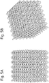
- the method of the present invention was also applied to a set of open cube-shaped lattice structures which were 3D printed. Two sets of lattice structures, each set comprising 3 lattice structures, were tested. The lattice structures within a set had the same lattice type, while lattice structures from different sets had different lattice structures.
- the lattice structure of the first set is shown in fig. 5a
- the lattice structure of the second set is shown in fig. 5b .
- the structures have been measured by means of Archimedes Measuring Method (Archi), two types of Gas Pycnometry and Impedance measurement by Foucault Current Measurement. Those methods confirm that both groups of 3 cubes occupy the same volume, have the same electrical resistance and all 6 have the same material density.
- the method of the present invention reveals the following: The first set of 3 identical cubes gives a quite good frequency uniformity (torsional mode). The last cube however shows a wider peak and thus higher damping, indicative of a higher internal friction, most often caused by microcracks.
- the present invention allows identifying microcrack defects by a widening of the frequency peak.
- the set extracted eigenfrequencies may comprise the peak eigenfrequency and the eigenfrequencies at half the peak height.
- the second set of 3 cubes shows a very significant difference in resonance behaviour: the first cube has a much higher elasticity compared to the second and the 3rd one, as indicated by the frequency difference (1 st cube: 20700 Hz, 2 nd cube: 21000 Hz, 3 rd cube: 21150 Hz for the torsional base mode).
- the inventors deem that the reason for this quite spectacular difference is the sintering quality responsible for better/poorer adhesion of the wires on the matrix points.
- the present invention is observed to be sensitive to deviating process behaviour, with a sensitivity which is better than other methods, such as an Archimedes Measuring Method, Gas Pycnometry and Impedance measurement method.
- the method of the present invention requires only about 20s per measurement if manually performed, but can be performed within 2s per measurement in a fully automated in-line mode.
Landscapes
- Chemical & Material Sciences (AREA)
- Engineering & Computer Science (AREA)
- Materials Engineering (AREA)
- Physics & Mathematics (AREA)
- Manufacturing & Machinery (AREA)
- Health & Medical Sciences (AREA)
- Acoustics & Sound (AREA)
- Life Sciences & Earth Sciences (AREA)
- Analytical Chemistry (AREA)
- Biochemistry (AREA)
- General Health & Medical Sciences (AREA)
- General Physics & Mathematics (AREA)
- Immunology (AREA)
- Pathology (AREA)
- Optics & Photonics (AREA)
- Mechanical Engineering (AREA)
- Investigating Or Analyzing Materials By The Use Of Ultrasonic Waves (AREA)
Priority Applications (7)
| Application Number | Priority Date | Filing Date | Title |
|---|---|---|---|
| EP21150518.5A EP4027138A1 (de) | 2021-01-07 | 2021-01-07 | Verbessertes verfahren und system zur überwachung von generativer fertigung |
| PCT/EP2022/050237 WO2022148827A1 (en) | 2021-01-07 | 2022-01-07 | Improved additive manufacturing monitoring method and system |
| JP2023541300A JP7807096B2 (ja) | 2021-01-07 | 2022-01-07 | 改良された付加製造監視方法およびシステム |
| KR1020237026382A KR20230147058A (ko) | 2021-01-07 | 2022-01-07 | 개선된 적층 제조 모니터링 방법 및 시스템 |
| EP22700585.7A EP4275038B1 (de) | 2021-01-07 | 2022-01-07 | Verbessertes verfahren und system zur überwachung von generativer fertigung |
| CN202280009061.7A CN116685454A (zh) | 2021-01-07 | 2022-01-07 | 改进的增材制造监测方法及系统 |
| US18/270,958 US20240300184A1 (en) | 2021-01-07 | 2022-01-07 | Improved additive manufacturing monitoring method and system |
Applications Claiming Priority (1)
| Application Number | Priority Date | Filing Date | Title |
|---|---|---|---|
| EP21150518.5A EP4027138A1 (de) | 2021-01-07 | 2021-01-07 | Verbessertes verfahren und system zur überwachung von generativer fertigung |
Publications (1)
| Publication Number | Publication Date |
|---|---|
| EP4027138A1 true EP4027138A1 (de) | 2022-07-13 |
Family
ID=74141369
Family Applications (2)
| Application Number | Title | Priority Date | Filing Date |
|---|---|---|---|
| EP21150518.5A Withdrawn EP4027138A1 (de) | 2021-01-07 | 2021-01-07 | Verbessertes verfahren und system zur überwachung von generativer fertigung |
| EP22700585.7A Active EP4275038B1 (de) | 2021-01-07 | 2022-01-07 | Verbessertes verfahren und system zur überwachung von generativer fertigung |
Family Applications After (1)
| Application Number | Title | Priority Date | Filing Date |
|---|---|---|---|
| EP22700585.7A Active EP4275038B1 (de) | 2021-01-07 | 2022-01-07 | Verbessertes verfahren und system zur überwachung von generativer fertigung |
Country Status (6)
| Country | Link |
|---|---|
| US (1) | US20240300184A1 (de) |
| EP (2) | EP4027138A1 (de) |
| JP (1) | JP7807096B2 (de) |
| KR (1) | KR20230147058A (de) |
| CN (1) | CN116685454A (de) |
| WO (1) | WO2022148827A1 (de) |
Cited By (1)
| Publication number | Priority date | Publication date | Assignee | Title |
|---|---|---|---|---|
| EP4238767A4 (de) * | 2020-10-30 | 2024-09-25 | Proterial, Ltd. | Zustandsüberwachungssystem und zustandsüberwachungsverfahren |
Families Citing this family (3)
| Publication number | Priority date | Publication date | Assignee | Title |
|---|---|---|---|---|
| EP4502566A1 (de) | 2023-08-04 | 2025-02-05 | GrindoSonic BV | Verfahren und system zur ermittlung der reissdehnung von 3d-gedruckten objekten |
| CN117982204B (zh) * | 2024-04-02 | 2024-08-16 | 北京速迈医疗科技有限公司 | 超声手术系统控制参数的确定方法、装置、设备及介质 |
| KR20260046799A (ko) * | 2024-09-30 | 2026-04-07 | 오스템임플란트 주식회사 | 출력 상태에 대한 정보를 제공하는 방법, 디바이스 및 기록매체 |
Citations (5)
| Publication number | Priority date | Publication date | Assignee | Title |
|---|---|---|---|---|
| US6782970B2 (en) | 2002-04-25 | 2004-08-31 | Schlumberger Technology Corporation | Acoustic source using a shaftless electrical hammer |
| EP3309544A1 (de) * | 2016-10-11 | 2018-04-18 | General Electric Company | Verfahren und system zur in-prozess-überwachung und -qualitätskontrolle von generativ gefertigten teilen |
| EP3435044A1 (de) | 2017-07-27 | 2019-01-30 | Aif Management Bvba | Vorrichtung und verfahren zur durchführung einer aufprallerregungstechnik |
| US20190234908A1 (en) * | 2018-01-31 | 2019-08-01 | Hexagon Technology Center Gmbh | Oscillation analysis on an object produced by means of additive manufacturing |
| US20200057030A1 (en) * | 2015-11-13 | 2020-02-20 | Honeywell Federal Manufacturing & Technologies, Llc | System and method for inspecting parts using dynamic response function |
Family Cites Families (9)
| Publication number | Priority date | Publication date | Assignee | Title |
|---|---|---|---|---|
| JPS58127162A (ja) * | 1982-01-25 | 1983-07-28 | Toshiba Corp | 空隙検出装置 |
| JP6061767B2 (ja) | 2013-04-17 | 2017-01-18 | リック株式会社 | コンクリート内部の剥離探査方法およびその装置 |
| WO2015157381A1 (en) * | 2014-04-10 | 2015-10-15 | United Technologies Corporation | Real-time resonant inspection for additive manufacturing |
| US20190011402A1 (en) | 2016-02-22 | 2019-01-10 | Nec Corporation | Inspection device, inspection method, and non-transitory recoding medium storing inspection program |
| US10857735B1 (en) | 2017-04-25 | 2020-12-08 | Hrl Laboratories, Llc | Apparatus and method for additive manufacturing and determining the development of stress during additive manufacturing |
| JP2018200198A (ja) | 2017-05-26 | 2018-12-20 | 本田技研工業株式会社 | 欠陥検出装置及び欠陥検出方法 |
| CN113874140B (zh) | 2019-05-31 | 2023-08-29 | 株式会社博迈立铖 | Fe-Al系合金减振零件及其制造方法 |
| EP3754331A1 (de) | 2019-06-20 | 2020-12-23 | GrindoSonic BVBA | Verfahren und system zur analyse eines prüfstücks mittels eines schwingungsantwortsignals |
| CN111272872B (zh) | 2020-02-14 | 2022-11-11 | 南方科技大学 | 裂纹检测方法及装置和增材制造系统 |
-
2021
- 2021-01-07 EP EP21150518.5A patent/EP4027138A1/de not_active Withdrawn
-
2022
- 2022-01-07 US US18/270,958 patent/US20240300184A1/en active Pending
- 2022-01-07 KR KR1020237026382A patent/KR20230147058A/ko active Pending
- 2022-01-07 JP JP2023541300A patent/JP7807096B2/ja active Active
- 2022-01-07 WO PCT/EP2022/050237 patent/WO2022148827A1/en not_active Ceased
- 2022-01-07 EP EP22700585.7A patent/EP4275038B1/de active Active
- 2022-01-07 CN CN202280009061.7A patent/CN116685454A/zh active Pending
Patent Citations (5)
| Publication number | Priority date | Publication date | Assignee | Title |
|---|---|---|---|---|
| US6782970B2 (en) | 2002-04-25 | 2004-08-31 | Schlumberger Technology Corporation | Acoustic source using a shaftless electrical hammer |
| US20200057030A1 (en) * | 2015-11-13 | 2020-02-20 | Honeywell Federal Manufacturing & Technologies, Llc | System and method for inspecting parts using dynamic response function |
| EP3309544A1 (de) * | 2016-10-11 | 2018-04-18 | General Electric Company | Verfahren und system zur in-prozess-überwachung und -qualitätskontrolle von generativ gefertigten teilen |
| EP3435044A1 (de) | 2017-07-27 | 2019-01-30 | Aif Management Bvba | Vorrichtung und verfahren zur durchführung einer aufprallerregungstechnik |
| US20190234908A1 (en) * | 2018-01-31 | 2019-08-01 | Hexagon Technology Center Gmbh | Oscillation analysis on an object produced by means of additive manufacturing |
Non-Patent Citations (5)
| Title |
|---|
| "Harmonic inversion of time signals and its applications", THE JOURNAL OF CHEMICAL PHYSICS, vol. 107, 1997, pages 6756 |
| HOSSEIN: "Nondestructive evaluation and in-situ monitoring for metal additive manufacturing", GRADUATE THESES AND DISSERTATIONS IOWA STATE UNIVERSITY, 2018, pages 16675 |
| J.TAPSON: "High precision, short range ultrasonic sensing by means of resonance mode-locking", ULTRASONICS, vol. 33, no. 6, 1995, pages 441 - 444, XP000548694, DOI: 10.1016/0041-624X(95)00052-5 |
| R.KAZYSR. SLITERISL. MAZEIKA: "Ultrasonic technique for Vibration Measurement", PROCEEDINGS OF THE 15TH WORLD CONFERENCE ON NON-DESTRUCTIVE TESTING, 15 October 2000 (2000-10-15), Retrieved from the Internet <URL:https://www.ndt.net/article/wcndt00/papers/idn246/idn246.htm> |
| S-R.HUANGR.M.LERNERK.J.PARKER: "Time domain Doppler estimators of the amplitude of vibrating targets", J. ACOUS. SOC. AM., vol. 91, no. 2, 1992, pages 965 - 974 |
Cited By (1)
| Publication number | Priority date | Publication date | Assignee | Title |
|---|---|---|---|---|
| EP4238767A4 (de) * | 2020-10-30 | 2024-09-25 | Proterial, Ltd. | Zustandsüberwachungssystem und zustandsüberwachungsverfahren |
Also Published As
| Publication number | Publication date |
|---|---|
| JP7807096B2 (ja) | 2026-01-27 |
| CN116685454A (zh) | 2023-09-01 |
| EP4275038A1 (de) | 2023-11-15 |
| EP4275038B1 (de) | 2025-01-01 |
| EP4275038C0 (de) | 2025-01-01 |
| US20240300184A1 (en) | 2024-09-12 |
| KR20230147058A (ko) | 2023-10-20 |
| JP2024503643A (ja) | 2024-01-26 |
| WO2022148827A1 (en) | 2022-07-14 |
Similar Documents
| Publication | Publication Date | Title |
|---|---|---|
| EP4275038B1 (de) | Verbessertes verfahren und system zur überwachung von generativer fertigung | |
| KR102859059B1 (ko) | 진동 응답 신호를 사용하여 시험편을 분석하기 위한 방법 및 시스템 | |
| US11137329B2 (en) | Apparatus and method for performing an impact excitation technique | |
| US10444110B2 (en) | System and method for inspecting parts using frequency response function | |
| Na et al. | Nondestructive evaluation method for standardization of fused filament fabrication based additive manufacturing | |
| JP2020537155A5 (de) | ||
| CN116964429A (zh) | 用于冲击测量的改进的支承 | |
| Barth et al. | Testing of ceramics by ultrasound microscopy and vibration analysis | |
| EP4227662A1 (de) | Verbesserter positioniertisch für aufprallerregungsmessungen | |
| WO2019092635A1 (en) | Method and system for manufacturing a component using an additive process | |
| JP2011133318A (ja) | 検査装置及びそれを用いた検査方法 | |
| Köhler et al. | Vibration Analysis for NDE of Ceramic Components | |
| KR20250026354A (ko) | 밀도 비대칭 측정 방법 및 장치 |
Legal Events
| Date | Code | Title | Description |
|---|---|---|---|
| PUAI | Public reference made under article 153(3) epc to a published international application that has entered the european phase |
Free format text: ORIGINAL CODE: 0009012 |
|
| STAA | Information on the status of an ep patent application or granted ep patent |
Free format text: STATUS: THE APPLICATION HAS BEEN PUBLISHED |
|
| AK | Designated contracting states |
Kind code of ref document: A1 Designated state(s): AL AT BE BG CH CY CZ DE DK EE ES FI FR GB GR HR HU IE IS IT LI LT LU LV MC MK MT NL NO PL PT RO RS SE SI SK SM TR |
|
| STAA | Information on the status of an ep patent application or granted ep patent |
Free format text: STATUS: THE APPLICATION IS DEEMED TO BE WITHDRAWN |
|
| 18D | Application deemed to be withdrawn |
Effective date: 20230114 |