EP4027962B1 - Pansement médical comprenant une couche de support ayant des caractéristiques en trois dimensions - Google Patents
Pansement médical comprenant une couche de support ayant des caractéristiques en trois dimensions Download PDFInfo
- Publication number
- EP4027962B1 EP4027962B1 EP20775212.2A EP20775212A EP4027962B1 EP 4027962 B1 EP4027962 B1 EP 4027962B1 EP 20775212 A EP20775212 A EP 20775212A EP 4027962 B1 EP4027962 B1 EP 4027962B1
- Authority
- EP
- European Patent Office
- Prior art keywords
- backing layer
- dressing
- layer
- dimensional features
- skin contact
- Prior art date
- Legal status (The legal status is an assumption and is not a legal conclusion. Google has not performed a legal analysis and makes no representation as to the accuracy of the status listed.)
- Active
Links
Images




Classifications
-
- A—HUMAN NECESSITIES
- A61—MEDICAL OR VETERINARY SCIENCE; HYGIENE
- A61F—FILTERS IMPLANTABLE INTO BLOOD VESSELS; PROSTHESES; DEVICES PROVIDING PATENCY TO, OR PREVENTING COLLAPSING OF, TUBULAR STRUCTURES OF THE BODY, e.g. STENTS; ORTHOPAEDIC, NURSING OR CONTRACEPTIVE DEVICES; FOMENTATION; TREATMENT OR PROTECTION OF EYES OR EARS; BANDAGES, DRESSINGS OR ABSORBENT PADS; FIRST-AID KITS
- A61F13/00—Bandages or dressings; Absorbent pads
- A61F13/02—Adhesive bandages or dressings
- A61F13/0203—Adhesive bandages or dressings with fluid retention members
- A61F13/0206—Adhesive bandages or dressings with fluid retention members with absorbent fibrous layers, e.g. woven or non-woven absorbent pads or island dressings
-
- A—HUMAN NECESSITIES
- A61—MEDICAL OR VETERINARY SCIENCE; HYGIENE
- A61F—FILTERS IMPLANTABLE INTO BLOOD VESSELS; PROSTHESES; DEVICES PROVIDING PATENCY TO, OR PREVENTING COLLAPSING OF, TUBULAR STRUCTURES OF THE BODY, e.g. STENTS; ORTHOPAEDIC, NURSING OR CONTRACEPTIVE DEVICES; FOMENTATION; TREATMENT OR PROTECTION OF EYES OR EARS; BANDAGES, DRESSINGS OR ABSORBENT PADS; FIRST-AID KITS
- A61F13/00—Bandages or dressings; Absorbent pads
- A61F13/02—Adhesive bandages or dressings
- A61F13/0203—Adhesive bandages or dressings with fluid retention members
- A61F13/0226—Adhesive bandages or dressings with fluid retention members characterised by the support layer
-
- A—HUMAN NECESSITIES
- A61—MEDICAL OR VETERINARY SCIENCE; HYGIENE
- A61F—FILTERS IMPLANTABLE INTO BLOOD VESSELS; PROSTHESES; DEVICES PROVIDING PATENCY TO, OR PREVENTING COLLAPSING OF, TUBULAR STRUCTURES OF THE BODY, e.g. STENTS; ORTHOPAEDIC, NURSING OR CONTRACEPTIVE DEVICES; FOMENTATION; TREATMENT OR PROTECTION OF EYES OR EARS; BANDAGES, DRESSINGS OR ABSORBENT PADS; FIRST-AID KITS
- A61F13/00—Bandages or dressings; Absorbent pads
- A61F13/02—Adhesive bandages or dressings
- A61F13/0276—Apparatus or processes for manufacturing adhesive dressings or bandages
Definitions
- the present disclosure generally relates to a medical dressing comprising a backing layer comprising three dimensional features.
- the present disclosure also relates to a method for preparing such a dressing.
- Adhesive medical dressings are frequently used in wound care, both for the purpose of treating wounds and scars and for the purpose of preventing these from occurring in the first place.
- One problem with adhesive dressings is their tendency to lose the adhesive connection to the skin of a wearer.
- the dressing When the dressing is applied to a body part that moves (e.g. at joints) and/or rubs against clothing or objects, the dressing may become partially or, in worst case, fully detached from the skin. Even partial detachment can compromise the function of the dressing, since compartments for body fluids between the skin and the adhesive skin surface of the dressing may be formed. As fluid accumulates, the compartments grow, and the wear time of the dressing is impaired. A detached dressing is difficult to re-apply, so the dressing typically needs to be replaced with a new dressing, which can be costly.
- the wear time may be particularly problematic for convex body parts, such as heels, knees and elbows, which may be referred to as "hard to dress-areas".
- border dressings comprise an absorbent pad, a backing layer and, an adhesive skin contact layer.
- the backing layer and, optionally, the adhesive skin contact layer extend peripherally beyond the pad to form a border portion.
- a border dressing is attached to the skin at the adhesive borders, or at the entire surface of the skin facing layer of the dressing.
- US2005059918 relates to a bordered wound dressing defining skin facing areas having different degrees of skin adherence
- the dressing comprises a backing layer defining a center portion and a border portion surrounding the center portion.
- detachment of the dressing may initiate at the edges of the absorbent pad.
- the backing layer is subjected to tension and extends obliquely from the pad, which is generally much thicker than the backing layer (and the skin contact layer). This way, air pockets may form around the edges of the pad. As the backing layer is stretched, the air pockets increase, leading to detachment of the dressing from the skin. Accumulation of fluids in the air pockets further impairs the wear time of the dressing.
- the mechanical tension on the backing layer may also cause shear stresses on the adhesive skin contact layer, that in turn results in detachment.
- a medical dressing as defined in claim 1.
- the present inventive concept is based on the insight that the flexibility of a medical dressing also poses demands on the backing layer of the dressing.
- the backing layer needs to conform with the movement of the body, and endure the stress applied during stretching of the dressing.
- the three dimensional features form extra material sections of the backing layer, and allow the backing layer to be stretched, e.g. due to bending of a knee, to a higher degree than if the backing layer was essentially flat.
- the three dimensional features flatten out to conform to the movement of the wearer.
- the three dimensional features may be formed in a zig-zag, grid or wave pattern extending across the surface of the backing layer.
- the three dimensional features are arranged in a discrete pattern across the surface of the backing layer. For example, a pattern of circular, oval, rectangular, elliptical, diamond or bean shaped three dimensional features may be envisioned.
- the pattern of three dimensional features extends over at least 30%, preferably at least 70%, and more preferably at least 90% of the surface area of the backing layer.
- the dressing has a longitudinal (y) direction and a lateral (x) direction, and the three dimensional features are arranged to extend in at least one of, preferably both of, the longitudinal (y) and the lateral (x) directions.
- the three dimensional features may be arranged to extend only, or substantially more, in the longitudinal (y), or lateral (x) directions. This may be beneficial if one would want to selectively steer the flexibility or stretching ability of the dressing in one particular direction.
- the three dimensional features have a height of between 0.3 and 10 mm, preferably between 0.5 and 5.0 mm, more preferably between 0.8 and 3.0 mm
- the backing layer comprises zones that are thinner than the remaining parts of the backing layer. This has the effect that the stretching ability of the backing material is improved, and thereby also the wear time. Furthermore, the breathability of the dressing is improved.
- the backing material in the slopes of each protrusion is thinner. This enhances the ability of the backing layer to stretch while also enhancing the breathability of the backing layer, and the dressing.
- the backing layer better conforms to the edges of the pad and minimizes gap formation around such edges.
- the absorbent pad may comprise a plurality of cuts extending at least partly through the absorbent pad.
- a method for forming a medical dressing as defined in claim 16.
- the backing layer is first heated to a temperature close to its melting point, and then subjected to a structured surface of the molding tool to form protrusions in the backing layer.
- the structured surface of the molding tool correspond to the pattern of three dimensional features to be formed in the backing layer.
- Step b) is preferably performed at a temperature between 10 and 50°C, preferably between 20 and 40°C. This is to cure the backing layer and affix the pattern of three dimensional features in the backing layer.
- the pattern of three dimensional features form depressions on the surface of the backing layer that is to contact the skin contact layer, and the absorbent pad, if present, when assembled, and protrusions on the opposing (second) surface of the backing layer (the outermost surface of the dressing).
- the method further comprises the step of stretching the backing layer by applying vacuum to the backing layer.
- the application of vacuum allows the backing layer to be stretched, and to provide a non-uniform thickness in the backing layer.
- step b) and step c) are performed simultaneously.
- FIG. 1 schematically illustrates a dressing 100 according to the prior art.
- the dressing comprises a wound contact layer 101 and a backing layer 102.
- a wound pad 103 is arranged between the backing layer 101 and the wound contact layer 102.
- the dressing is applied to a wound 104 formed on the skin 105 of a wearer.
- the dressing according to prior art has a higher tendency to detach from the skin 105 during use due to the formation of annular air pockets or air gaps 106 around the periphery of the wound pad 103. Pressure may build up in such gaps 106 during stretching or movement of the wearer.
- the backing layer 102 stretches obliquely from the pad 103 as well as downwards towards the underlying wound contact layer 102, creating a tension to the edges, and thus, detachment typically starts at the edges of the pad 103.
- the dressing when the dressing is applied to a wearer in vertical position, e.g. on a leg of a person standing, gravitational forces may force the exudate to leak from the wound pad 103 into the gap 106. As fluid accumulates, the detachment of the dressing is further impaired.
- Figure 2 schematically illustrates a dressing 200 according to the present disclosure, comprising an adhesive skin contact layer 201 and a backing layer 202, wherein the backing layer 202 has a first surface 207 facing the skin contact layer 201 and an opposing second surface 208, wherein the backing layer 202 comprises a plurality of three dimensional features 209 forming protrusions 210 on the second surface 208 of the backing layer 202 and depressions 211 on the first surface 207 of the backing layer 202.
- the skin contact layer 201 is substantially planar and adherent to the skin of a wearer.
- substantially planar means that the skin contact layer is substantially flat.
- the skin contact layer is void of protrusions.
- the skin contact layer is arranged not to follow the contour of the three dimensional features of the backing layer. In other words, the depressions formed in the first surface of the backing layer are not "occupied” by any part of the skin contact layer.
- an absorbent pad 203 is arranged between the backing layer 202 and the adhesive skin contact layer 201, wherein the backing layer 202 and the adhesive skin contact layer 201 extend around the periphery of the absorbent pad 203.
- a border portion 212 is formed by the adhesive skin contact layer 201 and the backing layer 202 around the pad 203 of the dressing 200.
- the absorbent pad 203 is substantially planar. In other words, the absorbent pad 203 is void of protrusions. The pad 203 does not follow the contour of the three dimensional features 209 of the backing layer 202.
- the present disclosure is by no means limited to the use of an absorbent pad 203, the advantages associated with the present disclosure are equally applicable to a dressing comprising only a backing layer 202 and a skin contact layer 201.
- border dressings are commonly used in the field, and the inventive concept is particularly beneficial for such dressings.
- the backing layer 202 comprising the three dimensional features 209 is arranged in close proximity to the edges of the absorbent pad 203 such that essentially no, or only a minor gap is formed around the periphery of the pad 203.
- the backing layer 202 conforms to the thicker pad 203 due to the extra backing layer material provided by the three dimensional features 209.
- the three dimensional features 209 flatten out and extend along with the movement of the wearer. The tension formed near the pad edges is thereby considerably reduced. Accordingly, the risk of detachment is reduced as well as the risk for pressure being built up around the edges of the pad 203.
- the backing layer 202 may be partially attached to the skin contact layer 201.
- the backing layer 202 may be partially attached to the absorbent pad 203, where present.
- the backing layer 202 may be partially attached to the skin contact layer 201, and to the absorbent pad 203 (if present) in the areas of the backing layer being void of three dimensional features 209.
- the backing layer 202 is partially attached to the skin-contact layer 203 in the area forming the border portion 212 of the dressing.
- the first surface 207 of the backing layer 202 is not adhesively attached to the skin contact layer 201 or the absorbent pad 203, if present, in the areas forming the depressions 211.
- the small gaps provided by the depressions 211 between the skin contact layer 201, and optionally the absorbent pad 203 and the backing layer 202 allows for the backing layer to be stretched when the dressing (and the patient) moves.
- the three dimensional features 209 flatten out. During stretching, the gaps formed by the depressions 211 of the first surface 207 will be reduced, and the top portions of the three dimensional features 209 may consequently contact the skin contact layer 201. However, when the dressing 200 returns to its non-stretched mode, this partial adhesive contact will substantially diminish, and the three dimensional features 209 will essentially return to their protruding pattern.
- the three dimensional features may be arranged in a discrete or continuous pattern across the backing layer as illustrated in figures 3a-d .
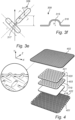
- Figure 3a illustrates a dressing 300, wherein the three dimensional features 309 are arranged in a discrete pattern 313 of "bean" shaped features across the surface of the backing layer 302.
- Figure 3b illustrates a dressing, wherein the three dimensional features 309 are arranged in a zig-zag pattern 314. Such a pattern may be particularly useful in embodiments where the dressing should be adapted to stretch more in the lateral (x) direction.
- Figure 3c illustrates a dressing, wherein the three dimensional features 309 are arranged in a discrete grid or "diamond" pattern.
- Figure 3d illustrates a pattern of discrete, circular three dimensional features 309.
- the pattern of three dimensional features 309 extends over at least 30%, preferably at least 70%, more preferably at least 90% of the surface area of the backing layer
- the pattern is arranged to extend over the entire surface area of the backing layer 302.
- the dressing has a longitudinal (y) direction and a lateral (x) direction, and the three dimensional features 309 are arranged to extend in at least one of, preferably both of, the longitudinal (y) and the lateral (x) directions.
- the flexibility of the dressing may be improved if the three dimensional features are arranged to extend in both the longitudinal (y) and the lateral (x) directions.
- the three dimensional features may be adapted to only extend, or extend significantly more, in one of the longitudinal (y) or the lateral (x) direction.
- dressings adapted for pressure ulcer prevention purposes e.g. a sacral dressing.
- a bedridden patient at risk of developing pressure ulcers may need assistance from a caregiver to be repositioned in bed.
- This lateral movement may cause stress to the dressing and the backing layer, and the dressing should preferably be flexible in direction of movement when re-positioned.
- the dressing (and the backing layer) is preferably stiffer in the longitudinal direction.
- the patterns of three dimensional features 309 also have the additional effect of improving the visual appearance of the dressing 300.
- a user may also be guided on how to apply the dressing correctly. For example, if the dressing is to be applied to a body part where stretching is particularly desired in one direction, the pattern may guide the user on how to apply the dressing to achieve this effect.
- the three dimensional features 309 have a height, h, of between 0.3 and 10 mm, preferably between 0.5 and 5.0 mm, more preferably between 1.0 and 3.0 mm.
- the "height” refers to the maximal extension of the three dimensional feature in the z direction, and is measured from the from the top of one protrusion to the flat surface of the backing layer.
- the backing layer has a non-uniform thickness.
- the backing layer comprises thinner material zones.
- the stretching ability is thereby improved, and accordingly, the wear time is enhanced.
- the breathability of the backing layer is improved, which is important for liquid handling.
- the backing layer is typically thinner in the areas where the three dimensional features are arranged than in the areas of the backing layer being void of three dimensional features.
- each three dimensional features 309 comprises a top portion 315, and at least one slope portion 316, wherein the thickness of the backing layer 302 in the top portion 315 of the three dimensional features 309 is higher than in the at least one slope portion 316 of the three dimensional features 309.
- the slope portion 316 may be at least 10% thinner, preferably at least 20% thinner, and more preferably at least 30% thinner than the top portion 315 of the three dimensional features 309.
- the length-to-width ratio of each of the three dimensional features 309 may be at least 2:1, preferably at least 3:1.
- a suitable width, w may be in the range of 0.5 mm - 10 mm, e.g. 2 mm - 5 mm.
- a suitable length, l may be in the range of 1 mm - 20 mm, e.g. 4 mm - 10 mm.
- the smallest space, a, between the three dimensional features may be at least 1 mm.
- the space between the three dimensional features is between 2 mm and 15 mm.
- the smallest space, a may e.g. be along a diagonal or oblique extension (relative to the longitudinal (y) and lateral (x) directions).
- the space, a, between the three dimensional features depends on the height of the three dimensional features.
- the space, a may be larger if the height of the three dimensional features is large, and vice versa.
- the area occupied by the three dimensional features (309) may be e.g. 10-50%, preferably 20-40% of the total area of the backing layer.
- the absorbent pad 403 comprises a plurality of cuts 421 extending at least partially through the absorbent pad.
- cuts 420 are provided in two of the pad layers 419 and 420, but it may be equally conceivable to only have cuts in one of the layers of the dressing.
- the cuts 421 illustrated in figure 4 are provided as discrete groups of incisions, wherein each group of incisions comprises three incisions extending from a common starting point.
- the angle between the incisions may be between 40 and 150°. In figure 4 , the angle between the incisions within one group 421 of incisions is 120°.
- the pad or pad layer(s) is/are cut in both the longitudinal (y) and lateral (x) directions of the pad such that the pad becomes flexible in all directions
- the backing layer may be a thin film, sheet or membrane that is vapor permeable.
- suitable materials for the backing layer include, but are not limited to polyurethane, polyethylene or polyamide films, silicone films, polyester based nonwoven materials, and laminates of polyester-based nonwoven materials and polyurethane films.
- the backing layer is a polyurethane film having a thickness of from 5 to 40 ⁇ m, e.g. from 15 to 25 ⁇ m.
- the pad according to the present disclosure may be formed from a single layer or multiple layers.
- the pad may comprise a foam or a gel. It may also comprise a superabsorbent material e.g. superabsorbent polymers (SAP) or superabsorbent fibers (SAF).
- a superabsorbent material e.g. superabsorbent polymers (SAP) or superabsorbent fibers (SAF).
- the absorbent pad may comprise two or more layers having different properties laminated together.
- the absorbent pad comprises a first absorbent layer, a liquid acquisition layer, e.g. a nonwoven, and a second absorbent layer.
- the first absorbent layer may be a superabsorbent layer and the second absorbent layer may comprise an absorbent foam.
- the liquid acquisition layer is arranged between the first and the second absorbent layer, wherein the second absorbent layer is the lowermost layer of the absorbent pad.
- Suitable foam materials for use in the second absorbent layer include, but are not limited to polyurethane foams.
- the superabsorbent layer may comprise a superabsorbent polymer (SAP) or superabsorbent fibers.
- SAP superabsorbent polymer
- a "superabsorbent polymer” or “SAP” is a polymer that can absorb up to 300 times its own weight in aqueous fluids.
- Superabsorbent polymers are constituted by water-swellable and water insoluble polymers capable of absorbing large quantities of fluid upon formation of a hydrogel.
- the superabsorbent polymers for use in accordance with the present disclosure may be inorganic or organic crosslinked hydrophilic polymers, such as polyvinyl alcohols, polyethylene oxides, crosslinked polyacrylates and the like.
- the superabsorbent (SAP) comprise sodium acrylate.
- the SAP material may be in the form of particles, fibers, flakes or similar.
- the liquid distributing layer may comprise any material having the ability to distribute the exudate in an efficient manner.
- the liquid distributing layer may comprise a nonwoven material.
- a nonwoven imparts an appropriately balanced rigidity to the layer and to the dressing as such. It may also efficiently distribute and spread liquid absorbed by the superabsorbent layer such that it can be evaporated through the backing layer over a large surface.
- the nonwoven may comprise viscose, polyester or blends thereof.
- the layers can be joined by adhesion, lamination, using pressure and heat.
- the absorbent pad may comprise additional layers, such as liquid transport layers, various combinations of foam and nonwoven layers laminated together.
- the layer 418 comprises an absorbent foam
- the layer 419 is a liquid acquisition layer
- the layer 420 is a superabsorbent layer.
- Such a layered pad construction prevents accumulation of body liquids close to the skin.
- the absorbent pad 403 may have a thickness in the range of from 1 to 10 mm. Preferably, the thickness of the pad is in the range of from 2.5 to 6 mm, e.g. from 3 to 5 mm. The thickness of the absorbent pad 403 is measured in a dry condition.
- skin contact layer means a layer that is in contact with the skin of a wearer.
- the skin contact layer is adapted to adhere to the skin, which may or may not comprise a wound.
- the skin contact layer comprises a silicone based adhesive.
- a silicone based adhesive is skin-friendly and permits the removal of the dressing without causing damage to the skin.
- the adhesive may comprise a soft silicone gel having a softness (penetration) of from 8 to 22 mm, e.g. from 12 to 17 mm, as measured by a method based on ASTM D 937 and DIN 51580, the method being described in European Patent Application No 14194054.4 .
- the skin contact layer may comprise one or several layers.
- the skin contact layer comprises a breathable polyolefin based film (e.g. polyethylene, polyamide, polyester, polyurethane) and a silicone adhesive layer.
- the skin contact layer 401 may be perforated, as illustrated in figure 4 .
- the perforations 422 typically extend through the skin contact layer 401.
- the perforations allow for a quick absorption into the pad 403 without compromising the tight fit to the skin provided by the adhesive layer.
- the perforations 422 may have different shapes and densities along varying regions of the skin contact layer 401, and may be arranged in a regular or irregular pattern.
- the thickness ratio between the backing layer and skin contact layer is typically at least 1:2, preferably at least 1:3.
- the present disclosure relates to a method for forming a backing layer for a medical dressing; the backing layer comprising a plurality of three dimensional features, wherein the method comprises:
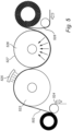
- Figure 5 schematically illustrates the formation of such a backing layer, by means of a roll-to-roll process.
- a backing layer 502 is fed onto a conveyor belt that transports the backing layer to a heating roll 523. Before heating, the backing layer 502 may be covered with a protective release layer 524, which is removed prior to heating.
- the surface of the heating roll 523 has a temperature between 100 and 200°C, preferably between 140 and 180°C, and the backing layer 502 is heated for a sufficient period of time, typically about 10-30 seconds, to almost reach its melting point.
- the heating of the backing layer may be achieved by irradiation from an infrared light source 525.
- the backing layer 502 is transferred to a second roll, i.e. a molding tool 526 having a surface comprising a pattern of three dimensional structures 527.
- This step b) is typically performed at a temperature between 10 and 50°C, preferably between 20 and 40°C.
- the backing layer 502 is thereby cured and affixed to the three dimensional structures 527 of the molding tool 526.
- vacuum may be applied to the first surface of the backing layer.
- the vacuum source may be an integral part of the molding tool 526 or it may be an external vacuum source.
- the vacuum application enhances the fixation of the three dimensional features in the backing layer 502. It also stretches the backing layer 502 such that a non-uniform thickness is obtained. Stretching of the backing layer while simultaneously contacting the surface of the backing layer with a structured molding tool 526 results in three dimensional features comprising slope portions being thinner than the corresponding top portions of the features.
- the test equipment 600 was a plastic plate 601 with a cylinder hinge 602 of a size to mimic an articulating joint, e.g. a knee (80mm in diameter).
- a polyurethane plastic film 603 was attached to the upper surface of the plate 601 to mimic the skin.
- the deviation in angle from the horizontal plane was approximately 10 degrees.
- the plate 601 was inclined by attaching a strap and the deviation from the horizontal plane was now approximately 55 degrees. Time (in seconds) was then measured from when the dressing 604 was applied until at least a part of the border portion of the dressing started detaching from the film 603.
- dressing E had the same construction as Dressing B and D above (5.2 mm foam pad), but differed with respect to the pattern of three dimensional features in the backing layer.
- the pattern of three dimensional features for the backing layer of dressing E was the pattern illustrated in figure 3c .
- the backing layer was embossed using a vacuum machine, Formech 300XQ, at 150-180°C. Vacuum and heat was applied and the backing layer was brought in contact with a metallic net 829 as illustrated in figure 8 .
- the diameter of the threads 830 was 1.0 mm, the width, w2, of each "diamond" 831 in the net pattern was 6.0 mm, and the length, l2, was 10 mm.
- the depth of each diamond (corresponding to the height of the three dimensional feature to be formed) was 1.2 mm.
- Dressing F had the same pattern of three dimensional features as Dressing E, but differed with respect to the construction of the absorbent pad.
- the pad comprised three different layers; i.e. from bottom-to-top: a polyurethane foam layer, a nonwoven layer and a superabsorbent layer).
- the superabsorbent layer and the nonwoven layer comprised cuts in accordance with layer 420 in figure 4 (where the cuts are illustrated as 421).
- the thickness of the absorbent pad of Dressing F was about 5 mm.
- the wear time was significantly improved with the dressings according to the present disclosure.
- the tests were stopped after 600 seconds, wherein Dressing F was still completely attached, with no signs of detachments. This may be attributed to a synergetic effect of inducing flexibility in both the wound pad (by means of the cuts in the pad-forming layer) and the backing layer (by means of the three dimensional features).
- Example 2 Evaluation of moisture vapor transmission
- Dressing F had the construction as defined hereinbefore. All dressings (F, G and H) had a similar construction, but differed with respect to the backing layer (see above with respect to the construction of dressing F).
- the backing layer of dressing H reference dressing
- the backing layer of inventive dressing F comprised a 20 ⁇ m polyurethane film with a pattern of three dimensional features as illustrated in figure 3c (diamond shaped three dimensional features), and the backing layer (a 20 ⁇ m polyurethane film) of dressing G had a pattern of three dimensional features as illustrated in figure 3d (circular three dimensional features).
- the patterns of three dimensional features were formed with the same machine equipment as explained hereinbefore.
- the metallic net utilized for forming the circular protrusion comprised circular structural features having a diameter of 4.7 mm, wherein the distance between the center of once circle to a neighboring circle was 6.7 mm.
- the depth of each circle (corresponding to the height of the three dimensional feature to be formed) was 2.0 mm.
- each product sample was placed on a transparent plastic paper (having a size of approximately 12x16 cm). The dry samples and the plastic paper were weighed (W 1 ). The plastic paper was removed after weighing and approximately 20 ml of liquid (tap water) was added to the product, through the skin contact layer. The liquid was added to the product by means of a plexiglas tube (having a length of 75 mm and inside diameter of 16 mm) attached to a circular plate (having a thickness of 11 mm and a diameter of 71 mm). The circular plate was used to form an even surface against the skin contact layer of the dressing and to secure an even distribution of liquid across the pad.
- a transparent plastic paper having a size of approximately 12x16 cm.
- the plastic paper was removed after weighing and approximately 20 ml of liquid (tap water) was added to the product, through the skin contact layer.
- the liquid was added to the product by means of a plexiglas tube (having a length of 75 mm and inside diameter of 16 mm) attached to
Landscapes
- Health & Medical Sciences (AREA)
- Engineering & Computer Science (AREA)
- Life Sciences & Earth Sciences (AREA)
- Biomedical Technology (AREA)
- Heart & Thoracic Surgery (AREA)
- Vascular Medicine (AREA)
- Animal Behavior & Ethology (AREA)
- General Health & Medical Sciences (AREA)
- Public Health (AREA)
- Veterinary Medicine (AREA)
- Manufacturing & Machinery (AREA)
- Materials For Medical Uses (AREA)
- Absorbent Articles And Supports Therefor (AREA)
Claims (16)
- Pansement médical (200) comprenant une couche adhésive de contact avec la peau (201) et une couche de support (202), dans lequel ladite couche de support (202) a une première surface (207) faisant face à ladite couche adhésive de contact avec la peau (201) et une seconde surface opposée (208), caractérisé en ce que ladite couche de support (202) comprend une pluralité de caractéristiques tridimensionnelles (209) formant des saillies (210) sur ladite seconde surface (208) de ladite couche de support (202) et des dépressions (211) sur ladite première surface (207) de ladite couche de support (202), et dans lequel ladite couche de support (202) a une épaisseur non uniforme.
- Pansement médical (200) selon la revendication 1, dans lequel ladite couche de contact avec la peau (201) est sensiblement plane.
- Pansement médical (200) selon la revendication 1 ou la revendication 2, comprenant en outre un tampon absorbant (203) agencé entre ladite couche de support (202) et ladite couche adhésive de contact avec la peau (201), dans lequel ladite couche de support (202) et ladite couche adhésive de contact avec la peau (201) s'étendent autour de la périphérie dudit tampon absorbant (203).
- Pansement médical (200) selon l'une quelconque des revendications précédentes, dans lequel ladite première surface (207) de ladite couche de support (202) n'est pas fixée de manière adhésive à ladite couche de contact avec la peau (201) ou audit tampon absorbant (203), s'il est présent, dans les zones formant lesdites dépressions (211).
- Pansement médical (200) selon l'une quelconque des revendications précédentes, dans lequel lesdites caractéristiques tridimensionnelles (209) sont agencées selon un motif discret ou continu à travers au moins une partie de ladite couche de support (202).
- Pansement médical (200) selon la revendication 5, dans lequel ledit motif de caractéristiques tridimensionnelles (209) s'étend sur au moins 30 %, de préférence au moins 70 %, et plus préférablement au moins 90 % de la surface de ladite couche de support (202) .
- Pansement médical (200) selon l'une quelconque des revendications précédentes, dans lequel ledit pansement (200) a une direction longitudinale (y) et une direction latérale (x), et dans lequel lesdites caractéristiques tridimensionnelles (209) sont agencées de manière à s'étendre dans au moins une, de préférence dans lesdites deux directions longitudinale (y) et latérale (x).
- Pansement médical (200) selon l'une quelconque des revendications précédentes, dans lequel lesdites caractéristiques tridimensionnelles (209) ont une hauteur comprise entre 0,3 et 10 mm, de préférence entre 0,5 et 5,0 mm, plus préférablement entre 1,0 et 3,0 mm.
- Pansement médical (200) selon l'une quelconque des revendications précédentes, dans lequel chaque caractéristique tridimensionnelle (209) comprend une partie supérieure (315), et au moins une partie inclinée (316), l'épaisseur de la couche de support (202) dans ladite partie supérieure (315) de ladite caractéristique tridimensionnelle (209) étant plus élevée que dans ladite au moins une partie inclinée (316) de ladite caractéristique tridimensionnelle (209) .
- Pansement médical (200) selon la revendication 9, dans lequel ladite ou lesdites parties inclinées (316) sont au moins 10 % plus minces, de préférence au moins 20 % plus minces, et plus préférablement au moins 30 % plus minces que ladite partie supérieure (315) de ladite caractéristique tridimensionnelle (209).
- Pansement médical (200) selon l'une quelconque des revendications précédentes, dans lequel ledit tampon absorbant (203) comprend une pluralité de découpes (421) s'étendant au moins partiellement à travers ledit tampon absorbant (203).
- Procédé de formation d'une couche de support (202) pour un pansement médical (200) ; la couche de support comprenant une pluralité de caractéristiques tridimensionnelles (209) et étant définie dans l'une quelconque des revendications 1 à 11, le procédé comprenant :- la prévision d'une couche de support (502),- la formation d'une pluralité de caractéristiques tridimensionnelles (209) dans ladite couche de support (502) par :a) chauffage de ladite couche de support (502) à une température comprise entre 100 et 200°C, de préférence entre 140 et 180°C etb) mise en contact d'une première surface de ladite couche de support (502) avec un outil de moulage (526) ayant une surface comprenant un motif de structures tridimensionnelles (527).
- Procédé selon la revendication 12, dans lequel ladite étape b) est effectuée à une température comprise entre 10 et 50°C, de préférence entre 20 et 40°C.
- Procédé selon la revendication 12 ou la revendication 13, comprenant en outre l'étape c) consistant à étirer ladite couche de support (502) en appliquant un vide à ladite couche de support (502).
- Procédé selon la revendication 14, dans lequel ladite étape b) et ladite étape c) sont exécutées simultanément.
- Procédé de formation d'un pansement médical (200) selon l'une quelconque des revendications 1-11 comprenant :- la prévision d'une couche de support (202) comprenant une pluralité de caractéristiques tridimensionnelles (209),- la disposition de ladite couche de support (202) sur une couche adhésive de contact avec la peau (201),- éventuellement la disposition d'un tampon absorbant (203) entre ladite couche de support (202) et ladite couche de contact avec la peau (201),ladite couche de support (202) ayant une première surface (207) faisant face à ladite couche de contact avec la peau (201) et une seconde surface opposée (208), et ladite pluralité de caractéristiques tridimensionnelles (209) étant formées para) chauffage de ladite couche de support (202) à une température comprise entre 100 et 200°C, de préférence entre 140 et 180°C etb) mise en contact de ladite première surface (207) de ladite couche de support (202) avec un outil de moulage (526) ayant une surface comprenant un motif de structures tridimensionnelles (527).
Applications Claiming Priority (2)
| Application Number | Priority Date | Filing Date | Title |
|---|---|---|---|
| EP19197307.2A EP3791838B1 (fr) | 2019-09-13 | 2019-09-13 | Pansement médical comprenant une couche de support ayant des caractéristiques en trois dimensions |
| PCT/EP2020/075328 WO2021048278A1 (fr) | 2019-09-13 | 2020-09-10 | Pansement médical comprenant une couche de support avec des caractéristiques tridimensionnelles |
Publications (3)
| Publication Number | Publication Date |
|---|---|
| EP4027962A1 EP4027962A1 (fr) | 2022-07-20 |
| EP4027962C0 EP4027962C0 (fr) | 2025-02-26 |
| EP4027962B1 true EP4027962B1 (fr) | 2025-02-26 |
Family
ID=67956584
Family Applications (2)
| Application Number | Title | Priority Date | Filing Date |
|---|---|---|---|
| EP19197307.2A Active EP3791838B1 (fr) | 2019-09-13 | 2019-09-13 | Pansement médical comprenant une couche de support ayant des caractéristiques en trois dimensions |
| EP20775212.2A Active EP4027962B1 (fr) | 2019-09-13 | 2020-09-10 | Pansement médical comprenant une couche de support ayant des caractéristiques en trois dimensions |
Family Applications Before (1)
| Application Number | Title | Priority Date | Filing Date |
|---|---|---|---|
| EP19197307.2A Active EP3791838B1 (fr) | 2019-09-13 | 2019-09-13 | Pansement médical comprenant une couche de support ayant des caractéristiques en trois dimensions |
Country Status (9)
| Country | Link |
|---|---|
| US (1) | US20220331167A1 (fr) |
| EP (2) | EP3791838B1 (fr) |
| JP (1) | JP2022547905A (fr) |
| CN (1) | CN114340572A (fr) |
| AU (1) | AU2020345005B2 (fr) |
| BR (1) | BR112022002083A2 (fr) |
| CA (1) | CA3151108A1 (fr) |
| ES (2) | ES3009525T3 (fr) |
| WO (1) | WO2021048278A1 (fr) |
Families Citing this family (2)
| Publication number | Priority date | Publication date | Assignee | Title |
|---|---|---|---|---|
| EP4389088A1 (fr) * | 2022-12-22 | 2024-06-26 | Mölnlycke Health Care AB | Pansement médical |
| EP4389089A1 (fr) * | 2022-12-22 | 2024-06-26 | Mölnlycke Health Care AB | Procédé de fabrication de pansements pour plaies |
Family Cites Families (12)
| Publication number | Priority date | Publication date | Assignee | Title |
|---|---|---|---|---|
| US5704905A (en) * | 1995-10-10 | 1998-01-06 | Jensen; Ole R. | Wound dressing having film-backed hydrocolloid-containing adhesive layer with linear depressions |
| US6600085B2 (en) * | 2000-12-19 | 2003-07-29 | Johnson & Johnson Consumer Products, Inc. | Absorbent article |
| US20040087884A1 (en) * | 2002-10-31 | 2004-05-06 | Haddock Teresa H. | Textured breathable films and their use as backing material for bandages |
| CN100536806C (zh) * | 2002-12-31 | 2009-09-09 | Bsn医疗有限责任公司 | 具有允许敷料膨胀的顺应元件的伤口敷料 |
| EP1675536B1 (fr) * | 2003-09-17 | 2016-01-20 | BSN medical GmbH | Pansement et procede de fabrication |
| JP5092105B2 (ja) * | 2007-03-13 | 2012-12-05 | アルケア株式会社 | カテーテル固定具及びカテーテル固定具用パッド |
| US9623223B2 (en) * | 2011-02-16 | 2017-04-18 | Revmedx, Inc. | Wound dressings comprising a plurality of liquid-expandable articles |
| US20120220973A1 (en) * | 2011-02-28 | 2012-08-30 | Jennifer Wing-Yee Chan | Adhesive bandage |
| US20140154459A1 (en) * | 2012-10-31 | 2014-06-05 | Kimberly-Clark Worldwide, Inc. | Fluid-Entangled Laminate Webs Having Hollow Projections and a Process and Apparatus for Making the Same |
| DK3085344T3 (da) * | 2015-04-21 | 2020-03-02 | Moelnlycke Health Care Ab | Sårpude og et selvklæbende element, omfattende en sårpude |
| JP7703139B2 (ja) * | 2017-04-11 | 2025-07-07 | ケンビュー・ブランズ・エルエルシー | 伸張可能な手当用品 |
| JP7326817B2 (ja) * | 2019-03-29 | 2023-08-16 | 凸版印刷株式会社 | 貼付剤支持体フィルム、積層体及び貼付剤 |
-
2019
- 2019-09-13 ES ES19197307T patent/ES3009525T3/es active Active
- 2019-09-13 EP EP19197307.2A patent/EP3791838B1/fr active Active
-
2020
- 2020-09-10 AU AU2020345005A patent/AU2020345005B2/en active Active
- 2020-09-10 WO PCT/EP2020/075328 patent/WO2021048278A1/fr not_active Ceased
- 2020-09-10 CA CA3151108A patent/CA3151108A1/fr active Pending
- 2020-09-10 BR BR112022002083A patent/BR112022002083A2/pt unknown
- 2020-09-10 CN CN202080062211.1A patent/CN114340572A/zh active Pending
- 2020-09-10 JP JP2022514818A patent/JP2022547905A/ja active Pending
- 2020-09-10 US US17/641,154 patent/US20220331167A1/en active Pending
- 2020-09-10 ES ES20775212T patent/ES3018142T3/es active Active
- 2020-09-10 EP EP20775212.2A patent/EP4027962B1/fr active Active
Also Published As
| Publication number | Publication date |
|---|---|
| AU2020345005A1 (en) | 2022-03-03 |
| EP4027962A1 (fr) | 2022-07-20 |
| WO2021048278A1 (fr) | 2021-03-18 |
| AU2020345005B2 (en) | 2025-08-14 |
| US20220331167A1 (en) | 2022-10-20 |
| JP2022547905A (ja) | 2022-11-16 |
| EP4027962C0 (fr) | 2025-02-26 |
| ES3018142T3 (en) | 2025-05-14 |
| CN114340572A (zh) | 2022-04-12 |
| ES3009525T3 (en) | 2025-03-27 |
| BR112022002083A2 (pt) | 2022-06-21 |
| EP3791838B1 (fr) | 2024-12-04 |
| CA3151108A1 (fr) | 2021-03-18 |
| EP3791838A1 (fr) | 2021-03-17 |
| EP3791838C0 (fr) | 2024-12-04 |
Similar Documents
| Publication | Publication Date | Title |
|---|---|---|
| US8377015B2 (en) | Wound dressing and method for producing it | |
| EP3700479B1 (fr) | Pansement à structure élastique soudée | |
| EP1893145B1 (fr) | Pansement | |
| JP4899019B2 (ja) | 傷手当用品とその製造方法 | |
| JP6089262B2 (ja) | 傷手当用品 | |
| US7745682B2 (en) | Wound dressing and method for manufacturing the same | |
| JP2006524757A (ja) | 通気性の弾性的なウェブ | |
| EP4027962B1 (fr) | Pansement médical comprenant une couche de support ayant des caractéristiques en trois dimensions | |
| EP4069173B1 (fr) | Tampons absorbants pour pansements | |
| KR20230035523A (ko) | 흡수성 상처 드레싱 | |
| JPH05501073A (ja) | 接着性ドレッシング | |
| HK1257767A1 (zh) | 伤口处理用品 |
Legal Events
| Date | Code | Title | Description |
|---|---|---|---|
| STAA | Information on the status of an ep patent application or granted ep patent |
Free format text: STATUS: UNKNOWN |
|
| STAA | Information on the status of an ep patent application or granted ep patent |
Free format text: STATUS: THE INTERNATIONAL PUBLICATION HAS BEEN MADE |
|
| PUAI | Public reference made under article 153(3) epc to a published international application that has entered the european phase |
Free format text: ORIGINAL CODE: 0009012 |
|
| STAA | Information on the status of an ep patent application or granted ep patent |
Free format text: STATUS: REQUEST FOR EXAMINATION WAS MADE |
|
| 17P | Request for examination filed |
Effective date: 20220223 |
|
| AK | Designated contracting states |
Kind code of ref document: A1 Designated state(s): AL AT BE BG CH CY CZ DE DK EE ES FI FR GB GR HR HU IE IS IT LI LT LU LV MC MK MT NL NO PL PT RO RS SE SI SK SM TR |
|
| DAV | Request for validation of the european patent (deleted) | ||
| DAX | Request for extension of the european patent (deleted) | ||
| STAA | Information on the status of an ep patent application or granted ep patent |
Free format text: STATUS: EXAMINATION IS IN PROGRESS |
|
| 17Q | First examination report despatched |
Effective date: 20231122 |
|
| GRAP | Despatch of communication of intention to grant a patent |
Free format text: ORIGINAL CODE: EPIDOSNIGR1 |
|
| STAA | Information on the status of an ep patent application or granted ep patent |
Free format text: STATUS: GRANT OF PATENT IS INTENDED |
|
| INTG | Intention to grant announced |
Effective date: 20240926 |
|
| GRAS | Grant fee paid |
Free format text: ORIGINAL CODE: EPIDOSNIGR3 |
|
| GRAA | (expected) grant |
Free format text: ORIGINAL CODE: 0009210 |
|
| STAA | Information on the status of an ep patent application or granted ep patent |
Free format text: STATUS: THE PATENT HAS BEEN GRANTED |
|
| AK | Designated contracting states |
Kind code of ref document: B1 Designated state(s): AL AT BE BG CH CY CZ DE DK EE ES FI FR GB GR HR HU IE IS IT LI LT LU LV MC MK MT NL NO PL PT RO RS SE SI SK SM TR |
|
| REG | Reference to a national code |
Ref country code: GB Ref legal event code: FG4D |
|
| REG | Reference to a national code |
Ref country code: CH Ref legal event code: EP |
|
| REG | Reference to a national code |
Ref country code: DE Ref legal event code: R096 Ref document number: 602020046811 Country of ref document: DE |
|
| REG | Reference to a national code |
Ref country code: IE Ref legal event code: FG4D |
|
| U01 | Request for unitary effect filed |
Effective date: 20250226 |
|
| U07 | Unitary effect registered |
Designated state(s): AT BE BG DE DK EE FI FR IT LT LU LV MT NL PT RO SE SI Effective date: 20250304 |
|
| PG25 | Lapsed in a contracting state [announced via postgrant information from national office to epo] |
Ref country code: RS Free format text: LAPSE BECAUSE OF FAILURE TO SUBMIT A TRANSLATION OF THE DESCRIPTION OR TO PAY THE FEE WITHIN THE PRESCRIBED TIME-LIMIT Effective date: 20250526 |
|
| PG25 | Lapsed in a contracting state [announced via postgrant information from national office to epo] |
Ref country code: PL Free format text: LAPSE BECAUSE OF FAILURE TO SUBMIT A TRANSLATION OF THE DESCRIPTION OR TO PAY THE FEE WITHIN THE PRESCRIBED TIME-LIMIT Effective date: 20250226 |
|
| PG25 | Lapsed in a contracting state [announced via postgrant information from national office to epo] |
Ref country code: NO Free format text: LAPSE BECAUSE OF FAILURE TO SUBMIT A TRANSLATION OF THE DESCRIPTION OR TO PAY THE FEE WITHIN THE PRESCRIBED TIME-LIMIT Effective date: 20250526 Ref country code: IS Free format text: LAPSE BECAUSE OF FAILURE TO SUBMIT A TRANSLATION OF THE DESCRIPTION OR TO PAY THE FEE WITHIN THE PRESCRIBED TIME-LIMIT Effective date: 20250626 |
|
| PG25 | Lapsed in a contracting state [announced via postgrant information from national office to epo] |
Ref country code: HR Free format text: LAPSE BECAUSE OF FAILURE TO SUBMIT A TRANSLATION OF THE DESCRIPTION OR TO PAY THE FEE WITHIN THE PRESCRIBED TIME-LIMIT Effective date: 20250226 |
|
| PG25 | Lapsed in a contracting state [announced via postgrant information from national office to epo] |
Ref country code: GR Free format text: LAPSE BECAUSE OF FAILURE TO SUBMIT A TRANSLATION OF THE DESCRIPTION OR TO PAY THE FEE WITHIN THE PRESCRIBED TIME-LIMIT Effective date: 20250527 |
|
| PG25 | Lapsed in a contracting state [announced via postgrant information from national office to epo] |
Ref country code: SM Free format text: LAPSE BECAUSE OF FAILURE TO SUBMIT A TRANSLATION OF THE DESCRIPTION OR TO PAY THE FEE WITHIN THE PRESCRIBED TIME-LIMIT Effective date: 20250226 |
|
| PGFP | Annual fee paid to national office [announced via postgrant information from national office to epo] |
Ref country code: GB Payment date: 20250923 Year of fee payment: 6 |
|
| PG25 | Lapsed in a contracting state [announced via postgrant information from national office to epo] |
Ref country code: CZ Free format text: LAPSE BECAUSE OF FAILURE TO SUBMIT A TRANSLATION OF THE DESCRIPTION OR TO PAY THE FEE WITHIN THE PRESCRIBED TIME-LIMIT Effective date: 20250226 |
|
| PG25 | Lapsed in a contracting state [announced via postgrant information from national office to epo] |
Ref country code: SK Free format text: LAPSE BECAUSE OF FAILURE TO SUBMIT A TRANSLATION OF THE DESCRIPTION OR TO PAY THE FEE WITHIN THE PRESCRIBED TIME-LIMIT Effective date: 20250226 |
|
| U20 | Renewal fee for the european patent with unitary effect paid |
Year of fee payment: 6 Effective date: 20250925 |
|
| PLBE | No opposition filed within time limit |
Free format text: ORIGINAL CODE: 0009261 |
|
| STAA | Information on the status of an ep patent application or granted ep patent |
Free format text: STATUS: NO OPPOSITION FILED WITHIN TIME LIMIT |
|
| PGFP | Annual fee paid to national office [announced via postgrant information from national office to epo] |
Ref country code: ES Payment date: 20251015 Year of fee payment: 6 |
|
| 26N | No opposition filed |
Effective date: 20251127 |