EP4028207B1 - Gerät und verfahren zur thermischen behandlung eines schrumpffutters - Google Patents
Gerät und verfahren zur thermischen behandlung eines schrumpffutters Download PDFInfo
- Publication number
- EP4028207B1 EP4028207B1 EP20774896.3A EP20774896A EP4028207B1 EP 4028207 B1 EP4028207 B1 EP 4028207B1 EP 20774896 A EP20774896 A EP 20774896A EP 4028207 B1 EP4028207 B1 EP 4028207B1
- Authority
- EP
- European Patent Office
- Prior art keywords
- cooling
- shrink fit
- cooling tube
- fit chuck
- holder
- Prior art date
- Legal status (The legal status is an assumption and is not a legal conclusion. Google has not performed a legal analysis and makes no representation as to the accuracy of the status listed.)
- Active
Links
Images

Classifications
-
- B—PERFORMING OPERATIONS; TRANSPORTING
- B23—MACHINE TOOLS; METAL-WORKING NOT OTHERWISE PROVIDED FOR
- B23P—METAL-WORKING NOT OTHERWISE PROVIDED FOR; COMBINED OPERATIONS; UNIVERSAL MACHINE TOOLS
- B23P11/00—Connecting or disconnecting metal parts or objects by metal-working techniques not otherwise provided for
- B23P11/02—Connecting or disconnecting metal parts or objects by metal-working techniques not otherwise provided for by first expanding and then shrinking or vice versa, e.g. by using pressure fluids; by making force fits
- B23P11/025—Connecting or disconnecting metal parts or objects by metal-working techniques not otherwise provided for by first expanding and then shrinking or vice versa, e.g. by using pressure fluids; by making force fits by using heat or cold
- B23P11/027—Connecting or disconnecting metal parts or objects by metal-working techniques not otherwise provided for by first expanding and then shrinking or vice versa, e.g. by using pressure fluids; by making force fits by using heat or cold for mounting tools in tool holders
-
- H—ELECTRICITY
- H05—ELECTRIC TECHNIQUES NOT OTHERWISE PROVIDED FOR
- H05B—ELECTRIC HEATING; ELECTRIC LIGHT SOURCES NOT OTHERWISE PROVIDED FOR; CIRCUIT ARRANGEMENTS FOR ELECTRIC LIGHT SOURCES, IN GENERAL
- H05B6/00—Heating by electric, magnetic or electromagnetic fields
- H05B6/02—Induction heating
- H05B6/10—Induction heating apparatus, other than furnaces, for specific applications
- H05B6/14—Tools, e.g. nozzles, rollers, calenders
-
- H—ELECTRICITY
- H05—ELECTRIC TECHNIQUES NOT OTHERWISE PROVIDED FOR
- H05B—ELECTRIC HEATING; ELECTRIC LIGHT SOURCES NOT OTHERWISE PROVIDED FOR; CIRCUIT ARRANGEMENTS FOR ELECTRIC LIGHT SOURCES, IN GENERAL
- H05B6/00—Heating by electric, magnetic or electromagnetic fields
- H05B6/02—Induction heating
- H05B6/36—Coil arrangements
- H05B6/40—Establishing desired heat distribution, e.g. to heat particular parts of workpieces
Definitions
- the invention relates to a device for the thermal treatment of a shrink chuck according to the preamble of patent claim 1.
- the invention further relates to a corresponding method when shrinking a tool into or out of the shrink chuck.
- a cooling device for a shrink chuck which has a diving chamber which is designed to accommodate the shrink chuck and can be filled with cooling liquid. There, the shrink chuck can be flushed with the cooling liquid while raising the liquid level in the stationary, tower-like diving chamber.
- the DE 10 1007 044097 A1 which discloses the preamble of claims 1 and 14, provides for a displacement of the tool holder, which can, however, endanger the operator.
- the traversing mechanics are also strongly influenced thermally.
- the invention is based on the object of further improving the devices and methods known in the prior art and of specifying a construction that can be operated and operated as simply and safely as possible for a quick and tool-friendly workflow.
- the cooling tube can be moved along a vertical guide by means of a lifting drive. This is to reduce the Susceptibility to faults is particularly advantageous if the lifting drive is located outside the cooling pipe and therefore has no direct contact with the coolant.
- cooling pipe is connected to the tank via a coolant line and can be filled with coolant in the cooling position while the tank is pressurized with compressed air.
- the shrink chuck is completely surrounded by a column of liquid when the cooling pipe is filled with cooling liquid.
- the cooling tube advantageously has a cylindrical sleeve which is axially aligned with a central axis of the shrink chuck to be cooled and at the lower end of which a base unit provided with passages for cooling liquid is arranged.
- the cooling tube or sleeve is transparent so that the operator can permanently see the tool holder. In particular, if a component is defective and the cooling process cannot be carried out as planned, the operator will see this and will not accidentally touch the still hot, uncooled tool holder.
- the capacity of the tank for coolant is preferably many times larger than the capacity of the cooling pipe.
- a further particularly preferred embodiment provides for an upper section of the cooling tube to be pressurized with compressed air Blowing unit is arranged for blow drying the shrink chuck.
- the blowing unit automatically blows the tool holder dry so that it is ready for use immediately after cooling without additional handling.
- a retaining sieve which engages in the free cross section of the cooling tube is arranged on the holder.
- heating unit which is preferably formed by an induction coil, can preferably be moved manually into a heating position acting on the shrink chuck.
- cooling tube automatically moves the heating unit away from the holder into a starting position when it is raised into the cooling position.
- the heating unit is guided along a wire rope and can be locked thereon by means of a wire rope holder.
- the wire rope holder can be released from its locking position by a release mechanism, e.g. a push button.
- the wire rope holder has a freewheel for unhindered lifting of the heating unit.
- the wire rope is stretched on a frame between two spaced-apart clamping points.
- a further advantageous embodiment provides that the linearly movable heating unit is connected to a power supply via a trailing cable.
- the heating unit forms a module that can be separated from the cooling unit and operated horizontally or vertically via a rotatable control/display panel.
- heating unit and the cooling unit are preferably releasably connected or connectable to one another via connecting means that can be operated without tools.
- the task mentioned at the beginning is achieved in that, in order to cool the shrink chuck, a cooling tube is moved into a cooling position enveloping the shrink chuck, the cooling tube being filled with a cooling liquid from a reservoir, the shrink chuck being held stationary in a holder, and wherein the cooling tube is moved from a release position lowered into a housing or frame into the cooling position.
- the heating unit is moved back and forth relative to the shrink chuck between a rest position and an active position.
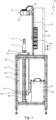
- the combined cooling and heating device 10 shown in the drawing is used to control the temperature of a shrink chuck 12 when shrinking in or out a shank tool 14, in particular a milling cutter or drill.
- a shank tool 14 in particular a milling cutter or drill.
- an inductive heating unit 16 and a cooling unit 18 designed as a liquid cooler is combined with one another in a modular manner on a device frame 20.
- the shrink chuck 12 can be positioned stationary in a receptacle or holder 22 that is fixed to the device.
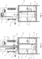
- the heating unit 16 can be made from the in Fig. 1 Starting position shown in Fig. 2 Heating position shown can be lowered. Due to the thermal expansion during inductive heating of the shrink chuck 12, it is then possible to insert or remove the tool 14.
- the cooling unit 18 can be removed from the in Fig. 1 Release position shown in Fig. 3 Raise the cooling position shown and fill with liquid.
- the cooling unit 18 comprises a cooling pipe 24, a lifting drive 26 for the cooling pipe and a reservoir or a tank 28 for coolant 30.
- the cooling pipe 24 can be automatically moved by means of the lifting drive 26 along a vertical guide formed by two parallel rods 32, 34.
- the lifting drive 26 can be formed, for example, by a rodless pneumatic driver cylinder, which is operated with compressed air. In the release position, the cooling tube 24 is lowered into a possibly housing-like closed area of the frame 20.
- the cooling pipe 24 is connected to the tank 28 via a coolant line 36 and can be filled with coolant 30 in the cooling position while the tank is pressurized with compressed air.
- the filling takes place at least to the extent that the shrink chuck 12 is completely surrounded by a liquid column 35, as shown in Fig. 3 is shown.
- a large amount of liquid can be displaced into the cooling pipe 24, which also circulates. Combined, this causes rapid heat dissipation from the hot shrink chuck 12.
- the capacity of the tank 28 for coolant 30 is many times larger, for example more than twice, than the capacity of the cooling pipe 24.
- the cooling tube 24 expediently has a cylindrical sleeve 38 which is axially aligned with a central axis or tool axis of rotation of the shrink chuck 12 to be cooled.
- This advantageously consists of a transparent material, for example acrylic glass, so that the operator can visually monitor all process steps.
- a base unit 42 provided with passages 40 for coolant, the structure of which consists of: Fig. 4 can be seen in more detail.
- a lower base plate 44 enables coupling to the lifting drive 26.
- the eccentrically arranged connecting sleeve 46 allows the connection of the coolant line 36.
- a cooling channel plate 48 sits on the base plate 44, which connects the radial passages 40 distributed in the circumferential direction via an annular channel 50 that communicates with the connecting sleeve 46 fed with coolant.
- Concentric O-rings 52 ensure a seal against the base plate 44.
- An axial bore 54 is provided for the central guide rod 34 to pass through, with sealing elements 56 preventing the passage of liquid.
- a blowing unit 58 that can be acted upon with compressed air is positioned at the top of the cooling pipe 24 as a further functional unit in order to enable blow drying of the shrink chuck 12 with compressed air when it is lowered without further action.
- the sleeve-shaped blowing unit 58 has a pneumatic connection 60, via which compressed air is supplied to an annular channel 62 and from there to blowing nozzles directed inwards into the cooling tube 24 and arranged at circumferential angular distances from one another 64 is distributed.
- a cover panel 66 with movable slats offers blow-off protection from the environment.
- a stationary retaining screen 68 is located between the holder 22 and the central rod 34 ( Fig. 2 ), which engages in its free cross section when the cooling tube 24 is raised.
- the heating unit 16 comprises an induction coil 70, which can be manually moved on a tower-like frame structure 72 from an upper starting position into a lower heating position acting on the shrink chuck 12. In the opposite direction, when the cooling tube 24 is lifted, the induction coil 70 is automatically moved away from the holder 22 back into the starting position.
- the induction coil 70 which can be moved vertically up and down in this way, is flexibly connected to a power supply via a trailing cable 74.
- the induction coil 70 can be moved along a wire rope 78 by means of a manually operated movement unit 76 and can be locked thereon by means of a wire rope holder 80.
- the wire rope holder 80 has a release mechanism in the form of a push button 82 to release the locking mechanism that prevents downward movement.
- a freewheel 84 is integrated into the wire rope holder 80.
- the wire rope 78 itself is fixed between two spaced-apart, frame-fixed clamping points 86, 88.
- heating unit 16 In principle, it is possible to remove the heating unit 16 from the frame 20 and operate it as a separate module, whereby in addition to the vertical orientation, a horizontal orientation is also possible.
- a control/display panel 90 that can be rotated manually or electronically through 90° can be provided.
- replaceable pole shoes can be kept ready in a magazine 92.
- Another user-friendly measure is that the heating unit 16 and the cooling unit 18 are releasably connected or connectable to one another via connecting means 94 that can be operated without tools.
Landscapes
- Physics & Mathematics (AREA)
- Electromagnetism (AREA)
- Engineering & Computer Science (AREA)
- Mechanical Engineering (AREA)
- Gripping On Spindles (AREA)
- Treatment Of Fiber Materials (AREA)
- Lining Or Joining Of Plastics Or The Like (AREA)
Description
- Die Erfindung betrifft ein Gerät zur thermischen Behandlung eines Schrumpffutters gemäß dem Oberbegriff des Patentanspruchs 1. Die Erfindung betrifft weiter ein entsprechendes Verfahren beim Ein/Ausschrumpfen eines Werkzeugs in das bzw. aus dem Schrumpffutter.
- Aus der
EP 1 470 888 A1 ist eine Kühlvorrichtung für ein Schrumpffutter bekannt, welche eine zur Aufnahme des Schrumpffutters ausgebildete, mit Kühlflüssigkeit befüllbare Tauchkammer aufweist. Dort ist das Schrumpffutter unter Anhebung des Flüssigkeitsspiegels in der stationär angeordneten, turmartigen Tauchkammer mit der Kühlflüssigkeit umspülbar. - Die
DE 10 1007 044097 A1 , die den Oberbegriff der Ansprüche 1 und 14 offenbart, sieht eine Verschiebung der Werkzeugaufnahme vor, was aber zu Gefährdungen des Bedieners führen kann. Darüber hinaus wird auch die Verfahrmechanik thermisch stark beeinflusst. - Ausgehend hiervon liegt der Erfindung die Aufgabe zugrunde, die im Stand der Technik bekannten Vorrichtungen und Verfahren weiter zu verbessern und eine möglichst einfach und sicher betreib- und bedienbare Konstruktion für einen schnellen und werkzeugschonenden Arbeitsablauf anzugeben.
- Zur Lösung dieser Aufgabe wird die im Patentanspruch 1 bzw. 14 angegebene Merkmalskombination vorgeschlagen. Vorteilhafte Ausgestaltungen und Weiterbildungen der Erfindung ergeben sich aus den abhängigen Ansprüchen.
- Die Erfindung geht von dem Gedanken aus, das Schrumpffutter in einer Halterung stationär zu halten und die Kühleinheit und ggf. die Heizeinheit entsprechend zuzustellen. Demzufolge wird erfindungsgemäß vorgeschlagen, dass die Halterung gerätefest angeordnet ist, und dass das Kühlrohr in der Freigabestellung in ein Gehäuse oder Gestell abgesenkt ist. Dadurch wird eine vereinfachte Handhabung mit reduzierten Bedienereingriffen und zugleich eine gleichmäßige und rasche Kühlung erreich, so dass auch keine unerwünschten Verformungen oder Verzug im Werkzeug auftreten. Im Einzelnen ergeben sich folgende vorteilhafte Effekte:
- Die Werkzeugaufnahme bzw. das Schrumpffutter kann direkt nach dem Schrumpfvorgang und automatisiert abgekühlt werden. Der Benutzer kommt erst mit der abgekühlten Werkzeugaufnahme wieder in Kontakt. Dies ist besonders in Sachen Arbeitssicherheit wichtig.
- Es kann eine große Menge an Flüssigkeit in das Kühlrohr gefördert werden, so dass eine schnelle Wärmeabfuhr von der heißen Werkzeugaufnahme weg möglich ist.
- Die Abkühlung ist unabhängig von der äußeren Gestalt bzw. Werkzeugkontur.
- Die Flüssigkeitssäule im Kühlrohr umschließt die Werkzeugaufnahme vollständig. Die Werkzeugaufnahme wird somit nicht punktuell abgekühlt, was ansonsten zu einem Verzug der Werkzeugaufnahme und damit zu Rundlauffehlern führen kann.
- Das Gerät ist konstruktiv einfach, da nur eine Lineareinheit benötigt wird, um den Abkühlprozess durchzuführen und ggf. die induktive Erwärmungseinheit wieder in die Ausganglage zu bringen.
- Vorteilhafterweise ist das Kühlrohr mittels eines Hubantriebs entlang einer Vertikalführung verfahrbar ist. Hierbei ist es zur Reduzierung der Störanfälligkeit besonders vorteilhaft, wenn der Hubantrieb sich außerhalb des Kühlrohrs befindet und somit keinen direkten Kontakt zur Kühlflüssigkeit hat.
- Eine weitere Vereinfachung auch hinsichtlich der Flüssigkeitsförderung ergibt sich dadurch, dass das Kühlrohr über eine Kühlflüssigkeitsleitung mit dem Tank verbunden ist und in der Kühlstellung unter Druckluftbeaufschlagung des Tanks mit Kühlflüssigkeit befüllbar ist.
- Vorteilhaft hinsichtlich einer raschen und gleichmäßigen Kühlung ist es auch, wenn das Schrumpffutter bei mit Kühlflüssigkeit befülltem Kühlrohr vollständig von einer Flüssigkeitssäule umschlossen ist.
- Vorteilhafterweise besitzt das Kühlrohr eine axial zu einer Mittelachse des abzukühlenden Schrumpffutters ausgerichtete, zylindrische Hülse, an deren unterem Stirnende eine mit Durchlässen für Kühlflüssigkeit versehene Bodeneinheit angeordnet ist. Vorzugsweise ist das Kühlrohr bzw. die Hülse transparent, so dass der Bediener dauerhaft die Werkzeugaufnahme sieht. Insbesondere bei einem Defekt einer Komponente, wenn der Abkühlvorgang nicht wie geplant durchgeführt werden kann, sieht dies der Bediener und fasst nicht versehentlich die noch heiße, ungekühlte Werkzeugaufnahme an.
- Um eine hohe Zyklenzahl und eine gute Wärmeabfuhr zu gewährleisten, ist es von Vorteil, wenn das Fassungsvermögen des Tanks für Kühlflüssigkeit vorzugsweise um ein Vielfaches größer als das Fassungsvermögen des Kühlrohrs ist.
- Eine weitere besonderes bevorzugte Ausgestaltung sieht vor, dass an einem oberen Abschnitt des Kühlrohrs eine mit Druckluft beaufschlagbare Blaseinheit zur Blastrocknung des Schrumpffutters angeordnet ist. Die Blaseinheit bläst automatisiert die Werkzeugaufnahme trocken, so dass diese ohne zusätzliches Handling direkt nach der Abkühlung einsatzbereit ist.
- Um die Gerätesicherheit weiter zu verbessern, ist es vorteilhaft, wenn an der Halterung ein in den freien Querschnitt des Kühlrohrs eingreifendes Rückhaltesieb angeordnet ist.
- Eine weitere Verbesserung ergibt sich dadurch, dass die vorzugsweise durch eine Induktionsspule gebildete Heizeinheit in eine auf das Schrumpffutter einwirkende Heizstellung vorzugsweise manuell verschiebbar ist.
- Eine weitere einfache Automatisierungsmöglichkeit ergibt sich dadurch, dass das Kühlrohr beim Anheben in die Kühlstellung die Heizeinheit von der Halterung weg in eine Ausgangsstellung selbsttätig mitbewegt.
- Um eine einfache Positionierung zu erlauben, ist es von Vorteil, wenn die Heizeinheit entlang einem Drahtseil geführt ist und daran mittels eines Drahtseilhalters arretierbar ist.
- Für eine weitere Handhabungsvereinfachung ist es günstig, wenn der Drahtseilhalter durch einen Auslösemechanismus, z.B. einen Druckknopf aus seiner Arretierungsstellung lösbar ist.
- Um eine Rückbewegung in die Ausgangsstellung zu vereinfachen, ist es vorteilhaft, wenn der Drahtseilhalter einen Freilauf für ein ungehindertes Anheben der Heizeinheit aufweist.
- Vorteilhafterweise ist das Drahtseil an einem Gestell zwischen zwei voneinander beabstandeten Klemmstellen gespannt ist.
- Eine weitere vorteilhafte Ausgestaltung sieht vor, dass die linear verfahrbare Heizeinheit über ein Schleppkabel mit einer Stromversorgung verbunden ist.
- Für einen flexiblen Einsatz ist es auch von Vorteil, wenn die Heizeinheit ein von der Kühleinheit trennbares, unter horizontaler oder vertikaler Ausrichtung über ein drehbares Bedien-/Anzeigefeld betreibbares Modul bildet.
- Eine weitere Verbesserung in dieser Hinsicht wird dadurch erreicht, dass die Heizeinheit und die Kühleinheit vorzugsweise über werkzeuglos betätigbare Verbindungsmittel lösbar miteinander verbunden bzw. verbindbar sind.
- In verfahrensmäßiger Hinsicht wird die eingangs genannte Aufgabe dadurch gelöst, dass zum Abkühlen des Schrumpffutters ein Kühlrohr in eine das Schrumpffutter umhüllende Kühlstellung bewegt wird, wobei das Kühlrohr aus einem Reservoir mit einer Kühlflüssigkeit befüllt wird, wobei das Schrumpffutter in einer Halterung stationär gehalten wird, und wobei das Kühlrohr aus einer in ein Gehäuse oder Gestell abgesenkten Freigabestellung in die Kühlstellung bewegt wird. Damit lassen sich die vorstehend erwähnten Vorteile gleichermaßen erzielen.
- Vorteilhafterweise wird die Heizeinheit relativ zu dem Schrumpffutter zwischen einer Ruhestellung und einer Wirkstellung hin und her bewegt.
- Im Folgenden wird die Erfindung anhand der in der Zeichnung in schematischer Weise dargestellten Ausführungsbeispiele näher erläutert. Es zeigen
- Fig. 1
- ein Gerät mit einer Heiz- und einer Kühleinheit zur thermischen Behandlung eines Schrumpffutters in einer Seitenansicht;
- Fig. 2
- das Gerät bei aktiver Heizeinheit in einer gegenüber
Fig. 1 um 90° gedrehten, teilweise geschnittenen Seitenansicht; - Fig. 3
- das Gerät bei aktiver Kühleinheit in
Fig. 2 entsprechender Seitenansicht; - Fig. 4
- eine bodenseitig in das Kühlrohr einsetzbare Bodeneinheit in einem Axialschnitt;
- Fig. 5
- eine Blaseinheit zum Aufsetzen auf das Kühlrohr der Kühleinheit in einem Axialschnitt; und
- Fig. 6
- einen Drahtseilhalter für die Heizeinheit in einer Seitenansicht.
- Das in der Zeichnung dargestellte kombinierte Kühl- und Heizgerät 10 dient zur Temperierung eines Schumpffutters 12 beim Ein- bzw. Ausschrumpfen eines Schaftwerkzeugs 14, insbesondere eines Fräsers oder Bohrers. Zu diesem Zweck sind eine induktiv arbeitende Heizeinheit 16 und eine als Flüssigkeitskühler ausgebildete Kühleinheit 18 an einem Gerätegestell 20 modulartig miteinander kombiniert.
- Das Schrumpffutter 12 lässt sich in einer gerätefest angeordneten Aufnahme bzw. Halterung 22 stationär positionieren. Zum Erwärmen des Schrumpffutters 12 kann die Heizeinheit 16 aus der in
Fig. 1 gezeigten Ausgangsstellung in die inFig. 2 gezeigte Heizstellung abgesenkt werden. Durch die thermische Ausdehnung beim induktiven Heizen des Schrumpffutters 12 ist es sodann möglich, das Werkzeug 14 einzusetzen oder zu entnehmen. Zum beschleunigten Abkühlen lässt sich die Kühleinheit 18 aus der inFig. 1 gezeigten Freigabestellung in die inFig. 3 gezeigte Kühlstellung anheben und mit Flüssigkeit befüllen. - Die Kühleinheit 18 umfasst ein Kühlrohr 24, einen Hubantrieb 26 für das Kühlrohr und ein Reservoir bzw. einen Tank 28 für Kühlflüssigkeit 30. Das Kühlrohr 24 ist mittels des Hubantriebs 26 entlang einer durch zwei parallele Stangen 32, 34 gebildeten Vertikalführung automatisch verfahrbar. Der Hubantrieb 26 kann beispielsweise durch einen kolbenstangenlosen pneumatischen Mitnehmerzylinder gebildet sein, welcher mit Pressluft betrieben wird. In der Freigabestellung ist das Kühlrohr 24 in einen ggf. gehäuseartig geschlossenen Bereich des Gestells 20 abgesenkt.
- Das Kühlrohr 24 ist über eine Kühlflüssigkeitsleitung 36 mit dem Tank 28 verbunden und in der Kühlstellung unter Druckluftbeaufschlagung des Tanks mit Kühlflüssigkeit 30 befüllbar. Die Befüllung erfolgt zumindest soweit, dass das Schrumpffutter 12 vollständig von einer Flüssigkeitssäule 35 umschlossen ist, wie es in
Fig. 3 gezeigt ist. Dabei kann eine große Menge an Flüssigkeit in das Kühlrohr 24 verdrängt werden, welche zusätzlich noch zirkuliert. Kombiniert bewirkt dies eine schnelle Wärmeabfuhr des heißen Schrumpffutters 12. In diesem Zusammenhang ist es auch vorteilhaft, wenn das Fassungsvermögen des Tanks 28 für Kühlflüssigkeit 30 um ein Vielfaches, bspw. um mehr als das Doppelte größer als das Fassungsvermögen des Kühlrohrs 24 ist. - Zweckmäßig weist das Kühlrohr 24 eine axial zu einer Mittelachse bzw. Werkzeugdrehachse des abzukühlenden Schrumpffutters 12 ausgerichtete, zylindrische Hülse 38 auf. Diese besteht vorteilhafterweise aus einem transparenten Material, bspw. Acrylglas, so dass der Bediener alle Prozessschritte unter Sichtkontrolle hat.
- Am unteren Stirnende der Hülse 38 ist eine mit Durchlässen 40 für Kühlflüssigkeit versehene Bodeneinheit 42 angeordnet, deren Aufbau aus
Fig. 4 näher ersichtlich ist. Eine untere Grundplatte 44 ermöglicht die Ankopplung an den Hubantrieb 26. Die exzentrisch angeordnete Verbindungshülse 46 erlaubt den Anschluss der Kühlflüssigkeitsleitung 36. Auf der Grundplatte 44 sitzt eine Kühlkanalplatte 48, welche die in Umfangsrichtung verteilten radialen Durchlässe 40 über einen mit der Verbindungshülse 46 kommunizierenden Ringkanal 50 mit Kühlflüssigkeit speist. Dabei sorgen konzentrische O-Ringe 52 für eine Abdichtung gegenüber der Grundplatte 44. Für den Durchgriff der zentralen Führungsstange 34 ist eine Axialbohrung 54 vorgesehen, wobei Abdichtelemente 56 einen Flüssigkeitsdurchtritt verhindern. - Wie auch aus
Fig. 5 ersichtlich, ist als weitere Funktionseinheit eine mit Druckluft beaufschlagbare Blaseinheit 58 oben an dem Kühlrohr 24 positioniert, um bei dessen Absenken ohne weiteres Zutun eine Blastrocknung des Schrumpffutters 12 mit Druckluft zu ermöglichen. Die hülsenförmige Blaseinheit 58 besitzt einen Pneumatikanschluss 60, über den Druckluft auf einen Ringkanal 62 und von dort auf nach innen in das Kühlrohr 24 gerichtete, in Umfangswinkelabständen voneinander angeordnete Blasdüsen 64 verteilt wird. Eine Abdeckblende 66 mit beweglichen Lamellen bietet dabei einen Abblasschutz gegenüber der Umgebung. - Um zu verhindern, dass Gegenstände ungewollt in die Kühleinheit 18 fallen, befindet sich zwischen der Halterung 22 und der zentralen Stange 34 ein stationäres Rückhaltesieb 68 (
Fig. 2 ), das beim Hochfahren des Kühlrohrs 24 in dessen freien Querschnitt eingreift. - Die Heizeinheit 16 umfasst eine Induktionsspule 70, die an einem turmartigen Gestellaufbau 72 aus einer oberen Ausgangsstellung in eine auf das Schrumpffutter 12 einwirkende untere Heizstellung manuell verschiebbar ist. In umgekehrter Richtung wird Induktionsspule 70 beim Anheben des Kühlrohrs 24 von der Halterung 22 weg in die Ausgangsstellung zurück selbsttätig mitbewegt. Die in dieser Weise vertikal auf und ab bewegbare Induktionsspule 70 ist über ein Schleppkabel 74 flexibel mit einer Stromversorgung verbunden.
- Zur vereinfachten Positionierung ist die Induktionsspule 70 mittels einer manuell handhabbaren Bewegungseinheit 76 entlang einem Drahtseil 78 bewegbar und daran mittels eines Drahtseilhalters 80 arretierbar.
- Wie am besten aus
Fig. 6 erkennbar, besitzt der Drahtseilhalter 80 einen Auslösemechanismus in Form eines Druckknopfes 82, um die gegen eine Bewegung nach unten wirkende Arretierung zu lösen. Um das selbsttätige Anheben beim Hochfahren des Kühlrohrs 24 zu erlauben, ist ein Freilauf 84 in den Drahtseilhalter 80 integriert. Das Drahtseil 78 selbst ist zwischen zwei voneinander beabstandeten, gestellfesten Klemmstellen 86, 88 fixiert. - Grundsätzlich ist es möglich, die Heizeinheit 16 von dem Gestell 20 abzunehmen und als gesondertes Modul zu betreiben, wobei neben der vertikalen auch eine horizontale Ausrichtung möglich ist. Um beide Betriebsarten zu unterstützen, kann ein manuell oder elektronisch um 90° drehbares Bedien-/Anzeigefeld 90 vorgesehen sein. Für eine Anpassung an unterschiedliche Durchmesser von Schrumpffuttern können auswechselbare Polschuhe in einem Magazin 92 bereitgehalten werden. Eine weitere bedienerfreundliche Maßnahme besteht darin, dass die Heizeinheit 16 und die Kühleinheit 18 über werkzeuglos betätigbare Verbindungsmittel 94 lösbar miteinander verbunden bzw. verbindbar sind.
Claims (15)
- Gerät zur thermischen Behandlung eines Schrumpffutters (12) mit einer zum Aufnehmen des Schrumpffutters (12) ausgebildeten Halterung (22), einer vorzugsweise induktiven Heizeinheit (16) zur Erwärmung des Schrumpffutters (12) und einer Kühleinheit (18) zur Abkühlung des Schrumpffutters (12), wobei die Kühleinheit (18) ein zwischen einer die Halterung (22) freigebenden Freigabestellung und einer die Halterung (22) umhüllenden Kühlstellung bewegliches Kühlrohr (24) aufweist, und wobei das Kühlrohr (24) aus einem Tank (28) mit einer Kühlflüssigkeit beaufschlagt ist, dadurch gekennzeichnet, dass die Halterung (22) gerätefest angeordnet ist, und dass das Kühlrohr (24) in der Freigabestellung in ein Gehäuse oder Gestell (20) abgesenkt ist.
- Gerät nach Anspruch 1, dadurch gekennzeichnet, dass das Kühlrohr (24) mittels eines Hubantriebs (26) entlang einer Vertikalführung (32,34) verfahrbar ist.
- Gerät nachAnspruch 1 oder 2, dadurch gekennzeichnet, dass das Kühlrohr (24) über eine Kühlflüssigkeitsleitung (36) mit dem Tank (28) verbunden ist und in der Kühlstellung unter Druckluftbeaufschlagung des Tanks (28) mit Kühlflüssigkeit befüllbar ist.
- Gerät nach einem der Ansprüche 1 bis 3, dadurch gekennzeichnet, dass das Schrumpffutter (12) bei mit Kühlflüssigkeit befülltem Kühlrohr (24) vollständig von einer Flüssigkeitssäule umschlossen ist.
- Gerät nach einem der Ansprüche 1 bis 4, dadurch gekennzeichnet, dass das Kühlrohr (24) eine axial zu einer Mittelachse des abzukühlenden Schrumpffutters (12) ausgerichtete, vorzugsweise transparente zylindrische Hülse (38) aufweist, an deren unterem Stirnende eine mit Durchlässen für Kühlflüssigkeit versehene Bodeneinheit (42) angeordnet ist.
- Gerät nach einem der Ansprüche 1 bis 5, dadurch gekennzeichnet, dass das Fassungsvermögen des Tanks (28) für Kühlflüssigkeit vorzugsweise um ein Vielfaches größer als das Fassungsvermögen des Kühlrohrs (24) ist.
- Gerät nach einem der Ansprüche 1 bis 6, dadurch gekennzeichnet, dass an einem oberen Abschnitt des Kühlrohrs (24) eine mit Druckluft beaufschlagbare Blaseinheit (58) zur Blastrocknung des Schrumpffutters (12) angeordnet ist.
- Gerät nach einem der Ansprüche 1 bis 7, dadurch gekennzeichnet, dass an der Halterung (22) ein in den freien Querschnitt des Kühlrohrs (24) eingreifendes Rückhaltesieb (68) angeordnet ist.
- Gerät nach einem der Ansprüche 1 bis 8, dadurch gekennzeichnet, dass die vorzugsweise durch eine Induktionsspule (78) gebildete Heizeinheit (16) in eine auf das Schrumpffutter (12) einwirkende Heizstellung vorzugsweise manuell verschiebbar ist.
- Gerät nach einem der Ansprüche 1 bis 9, dadurch gekennzeichnet, dass das Kühlrohr (24) beim Anheben in die Kühlstellung die Heizeinheit (16) von der Halterung (22) weg in eine Ausgangsstellung selbsttätig mitbewegt.
- Gerät nach einem der Ansprüche 1 bis 10, dadurch gekennzeichnet, dass die Heizeinheit (16) entlang einem Drahtseil (78) geführt ist und daran mittels eines Drahtseilhalters (80) arretierbar ist.
- Gerät nach Anspruch 11, dadurch gekennzeichnet, dass der Drahtseilhalter (76) einen Freilauf (84) für ein ungehindertes Anheben der Heizeinheit (16) aufweist.
- Gerät nach einem der Ansprüche 1 bis 13, dadurch gekennzeichnet, dass die Heizeinheit (16) und die Kühleinheit (18) vorzugsweise über werkzeuglos betätigbare Verbindungsmittel (94) lösbar miteinander verbunden bzw. verbindbar sind.
- Verfahren zur thermischen Behandlung eines Schrumpffutters (12) beim Ein/Ausschrumpfen eines Werkzeugs umfassend zumindest die folgenden Schritte:a) Erwärmen des Schrumpffutters (12) durch eine induktive Heizeinheit (16),b) Abkühlen des Schrumpffutters (12) durch eine Kühleinheit (18), wobei ein Kühlrohr (24) in eine das Schrumpffutter (12) umhüllende Kühlstellung bewegt wird und das Kühlrohr (24) aus einem Reservoir (28) mit einer Kühlflüssigkeit befüllt wird,dadurch gekennzeichnet, dass
das Schrumpffutter (12) in einer Halterung (22) stationär gehalten wird, und dass in Schritt b) das Kühlrohr (24) aus einer in ein Gehäuse oder Gestell (20) abgesenkten Freigabestellung in die Kühlstellung bewegt wird.. - Verfahren nach Anspruch 14, dadurch gekennzeichnet, dass in Schritt a) die Heizeinheit (16) relativ zu dem Schrumpffutter (12) zwischen einer Ruhestellung und einer Wirkstellung hin und her bewegt wird.
Applications Claiming Priority (2)
| Application Number | Priority Date | Filing Date | Title |
|---|---|---|---|
| DE102019124469.2A DE102019124469A1 (de) | 2019-09-11 | 2019-09-11 | Gerät und Verfahren zur thermischen Behandlung eines Schrumpffutters |
| PCT/EP2020/074910 WO2021048040A1 (de) | 2019-09-11 | 2020-09-07 | Gerät und verfahren zur thermischen behandlung eines schrumpffutters |
Publications (2)
| Publication Number | Publication Date |
|---|---|
| EP4028207A1 EP4028207A1 (de) | 2022-07-20 |
| EP4028207B1 true EP4028207B1 (de) | 2023-10-18 |
Family
ID=72560544
Family Applications (1)
| Application Number | Title | Priority Date | Filing Date |
|---|---|---|---|
| EP20774896.3A Active EP4028207B1 (de) | 2019-09-11 | 2020-09-07 | Gerät und verfahren zur thermischen behandlung eines schrumpffutters |
Country Status (4)
| Country | Link |
|---|---|
| EP (1) | EP4028207B1 (de) |
| CN (1) | CN114341373B (de) |
| DE (1) | DE102019124469A1 (de) |
| WO (1) | WO2021048040A1 (de) |
Families Citing this family (3)
| Publication number | Priority date | Publication date | Assignee | Title |
|---|---|---|---|---|
| CN116197605A (zh) * | 2023-02-15 | 2023-06-02 | 苏州雷稀诺精密工具有限公司 | 一种刀具热装机辅助冷却机构 |
| CN116393915B (zh) * | 2023-06-07 | 2023-09-08 | 太原理工大学 | 一种大型薄壁管件热套加工装置及方法 |
| CN121042827B (zh) * | 2025-11-03 | 2026-01-13 | 烟台金泰美林科技股份有限公司 | 一种陶瓷阀门高精度热配装置及工艺 |
Family Cites Families (12)
| Publication number | Priority date | Publication date | Assignee | Title |
|---|---|---|---|---|
| DE20320999U1 (de) | 2003-04-23 | 2005-12-01 | Helmut Diebold Gmbh & Co. Goldring-Werkzeugfabrik | Kühlvorrichtung für Schrumpffutter |
| JP4897478B2 (ja) * | 2003-05-07 | 2012-03-14 | エス・エム・エス・ジーマーク・アクチエンゲゼルシャフト | スラブ或いはシートを冷却槽内の水中で冷却する、或いは焼入れする装置 |
| JP2006193764A (ja) * | 2005-01-11 | 2006-07-27 | Hirose Technology Kk | 高周波熱処理装置 |
| WO2007028522A2 (de) * | 2005-09-09 | 2007-03-15 | Franz Haimer Maschinenbau Kg | Vorrichtung und verfahren zur kühlung von schrumpffuttern bzw.vorrichtung zur aufnahme von werkzeugfuttern |
| DE202006005517U1 (de) * | 2006-04-03 | 2007-05-16 | Rineck Gmbh Maschinenbau | Induktionsschrumpfvorrichtung zum Wechseln von Werkzeugen, wie Bohrer, Fräser o.dgl. in einem Werkzeughalter |
| DE102006045871B4 (de) * | 2006-09-28 | 2010-01-28 | Rothe Erde Gmbh | Verfahren zur thermomechanischen Behandlung von nahtlos auf Radial-Axial-Ringwalzmaschinen hergestellten Ringen |
| DE102007044097B4 (de) * | 2007-09-14 | 2014-02-13 | Oesterle + Partner GbR (vertretungsberechtigte Gesellschafter: Hermann Oesterle, 72202 Nagold; Harald Öschger, 79312 Emmendingen) | Vorrichtung zum thermisch-induzierten Einspannen und/oder Ausspannen von Werkzeugen in eine bzw. aus einer Werkzeugaufnahme |
| US20100051610A1 (en) * | 2008-08-27 | 2010-03-04 | Parlec, Inc. | Combination tool presetter and induction heat-shrink apparatus |
| CN103849732A (zh) * | 2012-11-28 | 2014-06-11 | 大连圣特金属新材料研发有限公司 | 一种防变形循环水冷淬火槽 |
| DE202013007878U1 (de) * | 2013-09-04 | 2013-09-25 | KARL SCHÜSSLER GmbH & Co. KG | Vorrichtung zur Luftkühlung eines Schrumpfspannfutters |
| CN208701127U (zh) * | 2018-06-29 | 2019-04-05 | 吴春燕 | 一种淬火用升降装置 |
| CN110102744B (zh) * | 2019-05-31 | 2025-02-07 | 深圳市粤鹏金珠宝金行有限公司 | 熔融冷却装置 |
-
2019
- 2019-09-11 DE DE102019124469.2A patent/DE102019124469A1/de active Pending
-
2020
- 2020-09-07 EP EP20774896.3A patent/EP4028207B1/de active Active
- 2020-09-07 CN CN202080064051.4A patent/CN114341373B/zh active Active
- 2020-09-07 WO PCT/EP2020/074910 patent/WO2021048040A1/de not_active Ceased
Also Published As
| Publication number | Publication date |
|---|---|
| DE102019124469A1 (de) | 2021-03-11 |
| WO2021048040A1 (de) | 2021-03-18 |
| CN114341373A (zh) | 2022-04-12 |
| CN114341373B (zh) | 2025-10-31 |
| EP4028207A1 (de) | 2022-07-20 |
Similar Documents
| Publication | Publication Date | Title |
|---|---|---|
| EP0297034A2 (de) | Magazin mit Wechselvorrichtung | |
| DE102019124469A1 (de) | Gerät und Verfahren zur thermischen Behandlung eines Schrumpffutters | |
| DE2630232C2 (de) | Automatische Abstichmaschine für den Abstich bei elektrischen Hochöfen und Öfen für die Herstellung von Legierungen o.dgl. | |
| DE2557726A1 (de) | Vorrichtung zum auswechseln von giessrohren, insbesondere fuer einen mit einem schieberverschluss absperrbaren ausguss an einem zwischenbehaelter von stranggussanlagen | |
| DE3217169C2 (de) | Falzmesserzylinder | |
| DE1589851B2 (de) | Einrichtung zum handhaben von kernelementen in einem kernreaktor | |
| EP1927429A1 (de) | Werkzeugmaschine mit Werkzeugmagazin | |
| DE1627730B2 (de) | Vorrichtung zum Aufbringen von Befestigungselementen auf Schrauben bolzen | |
| EP1210995A1 (de) | Maschine für die Bearbeitung von Werkstücken, insbesondere von Blechen, mit wenigstens einer Biegestation sowie wenigstens einer Fügevorrichtung | |
| DE2344266C3 (de) | Greifvorrichtung, insbesondere für Steuer- und Abschaltstäbe in einem Kernreaktor | |
| DE69208135T2 (de) | Brennstoffladegreifer für Kernreaktoren | |
| DE69017393T2 (de) | Verfahren für das Ersetzen einer Heizung eines Druckausgleichgefässes in einem Kernreaktor und in einem solchen Verfahren verwendete Vorrichtung. | |
| EP0630313B1 (de) | Manipulator | |
| EP0266655B1 (de) | Wechselvorrichtung für den Schneckenzylinder einer Spritzgiessmaschine | |
| DE3315569A1 (de) | Verfahren und maschine zur manipulation von bohrstangen | |
| DE202004004424U1 (de) | Einrichtung zum thermischen Spannen und Entspannen von Werkzeugen in Schrumpffuttern | |
| DE19547885C1 (de) | Lanzenmanipulator mit Pneumatik-Lanzenhalter | |
| EP0252375A1 (de) | Verfahren zum Reparieren eines Kernreaktorbrennelementes und Austauschstab für ein solches Verfahren | |
| DE1602455A1 (de) | Vorrichtung zur Durchfuehrung von Operationen an den Enden von Rohren,die in cmem Waermetauscher angeordnet sind | |
| EP0811460A1 (de) | Werkzeugmaschine | |
| DE102007048291B3 (de) | Vorrichtung zum Ausrichten von Brennelementen in einem Druckwasserreaktor | |
| DE2312309C3 (de) | Vorrichtung zum Schweißen von Rohrteilen | |
| EP0271474B1 (de) | Vorrichtung zum Ausbau von in die Abstichöffnung metallurgischer Gefässe eingesetzten Lochsteinen | |
| DE102016013245A1 (de) | Bohrgerät für das Bearbeiten von Rohren in radioaktiver Umgebung | |
| DE3308444A1 (de) | Werkzeugsupport an einer drehmaschine mit schwenkbarem werkzeugkopf und werkzeugwechselvorrichtung |
Legal Events
| Date | Code | Title | Description |
|---|---|---|---|
| STAA | Information on the status of an ep patent application or granted ep patent |
Free format text: STATUS: UNKNOWN |
|
| STAA | Information on the status of an ep patent application or granted ep patent |
Free format text: STATUS: THE INTERNATIONAL PUBLICATION HAS BEEN MADE |
|
| PUAI | Public reference made under article 153(3) epc to a published international application that has entered the european phase |
Free format text: ORIGINAL CODE: 0009012 |
|
| STAA | Information on the status of an ep patent application or granted ep patent |
Free format text: STATUS: REQUEST FOR EXAMINATION WAS MADE |
|
| 17P | Request for examination filed |
Effective date: 20220308 |
|
| AK | Designated contracting states |
Kind code of ref document: A1 Designated state(s): AL AT BE BG CH CY CZ DE DK EE ES FI FR GB GR HR HU IE IS IT LI LT LU LV MC MK MT NL NO PL PT RO RS SE SI SK SM TR |
|
| DAV | Request for validation of the european patent (deleted) | ||
| DAX | Request for extension of the european patent (deleted) | ||
| GRAP | Despatch of communication of intention to grant a patent |
Free format text: ORIGINAL CODE: EPIDOSNIGR1 |
|
| STAA | Information on the status of an ep patent application or granted ep patent |
Free format text: STATUS: GRANT OF PATENT IS INTENDED |
|
| RIC1 | Information provided on ipc code assigned before grant |
Ipc: H05B 6/14 20060101ALI20230502BHEP Ipc: H05B 6/40 20060101ALI20230502BHEP Ipc: B23P 11/02 20060101AFI20230502BHEP |
|
| INTG | Intention to grant announced |
Effective date: 20230526 |
|
| GRAS | Grant fee paid |
Free format text: ORIGINAL CODE: EPIDOSNIGR3 |
|
| GRAA | (expected) grant |
Free format text: ORIGINAL CODE: 0009210 |
|
| STAA | Information on the status of an ep patent application or granted ep patent |
Free format text: STATUS: THE PATENT HAS BEEN GRANTED |
|
| AK | Designated contracting states |
Kind code of ref document: B1 Designated state(s): AL AT BE BG CH CY CZ DE DK EE ES FI FR GB GR HR HU IE IS IT LI LT LU LV MC MK MT NL NO PL PT RO RS SE SI SK SM TR |
|
| REG | Reference to a national code |
Ref country code: GB Ref legal event code: FG4D Free format text: NOT ENGLISH |
|
| REG | Reference to a national code |
Ref country code: CH Ref legal event code: EP |
|
| REG | Reference to a national code |
Ref country code: DE Ref legal event code: R096 Ref document number: 502020005713 Country of ref document: DE |
|
| REG | Reference to a national code |
Ref country code: IE Ref legal event code: FG4D Free format text: LANGUAGE OF EP DOCUMENT: GERMAN |
|
| REG | Reference to a national code |
Ref country code: LT Ref legal event code: MG9D |
|
| REG | Reference to a national code |
Ref country code: NL Ref legal event code: MP Effective date: 20231018 |
|
| PG25 | Lapsed in a contracting state [announced via postgrant information from national office to epo] |
Ref country code: NL Free format text: LAPSE BECAUSE OF FAILURE TO SUBMIT A TRANSLATION OF THE DESCRIPTION OR TO PAY THE FEE WITHIN THE PRESCRIBED TIME-LIMIT Effective date: 20231018 |
|
| PG25 | Lapsed in a contracting state [announced via postgrant information from national office to epo] |
Ref country code: GR Free format text: LAPSE BECAUSE OF FAILURE TO SUBMIT A TRANSLATION OF THE DESCRIPTION OR TO PAY THE FEE WITHIN THE PRESCRIBED TIME-LIMIT Effective date: 20240119 |
|
| PG25 | Lapsed in a contracting state [announced via postgrant information from national office to epo] |
Ref country code: IS Free format text: LAPSE BECAUSE OF FAILURE TO SUBMIT A TRANSLATION OF THE DESCRIPTION OR TO PAY THE FEE WITHIN THE PRESCRIBED TIME-LIMIT Effective date: 20240218 |
|
| PG25 | Lapsed in a contracting state [announced via postgrant information from national office to epo] |
Ref country code: LT Free format text: LAPSE BECAUSE OF FAILURE TO SUBMIT A TRANSLATION OF THE DESCRIPTION OR TO PAY THE FEE WITHIN THE PRESCRIBED TIME-LIMIT Effective date: 20231018 |
|
| PG25 | Lapsed in a contracting state [announced via postgrant information from national office to epo] |
Ref country code: ES Free format text: LAPSE BECAUSE OF FAILURE TO SUBMIT A TRANSLATION OF THE DESCRIPTION OR TO PAY THE FEE WITHIN THE PRESCRIBED TIME-LIMIT Effective date: 20231018 |
|
| PG25 | Lapsed in a contracting state [announced via postgrant information from national office to epo] |
Ref country code: LT Free format text: LAPSE BECAUSE OF FAILURE TO SUBMIT A TRANSLATION OF THE DESCRIPTION OR TO PAY THE FEE WITHIN THE PRESCRIBED TIME-LIMIT Effective date: 20231018 Ref country code: IS Free format text: LAPSE BECAUSE OF FAILURE TO SUBMIT A TRANSLATION OF THE DESCRIPTION OR TO PAY THE FEE WITHIN THE PRESCRIBED TIME-LIMIT Effective date: 20240218 Ref country code: GR Free format text: LAPSE BECAUSE OF FAILURE TO SUBMIT A TRANSLATION OF THE DESCRIPTION OR TO PAY THE FEE WITHIN THE PRESCRIBED TIME-LIMIT Effective date: 20240119 Ref country code: ES Free format text: LAPSE BECAUSE OF FAILURE TO SUBMIT A TRANSLATION OF THE DESCRIPTION OR TO PAY THE FEE WITHIN THE PRESCRIBED TIME-LIMIT Effective date: 20231018 Ref country code: BG Free format text: LAPSE BECAUSE OF FAILURE TO SUBMIT A TRANSLATION OF THE DESCRIPTION OR TO PAY THE FEE WITHIN THE PRESCRIBED TIME-LIMIT Effective date: 20240118 Ref country code: PT Free format text: LAPSE BECAUSE OF FAILURE TO SUBMIT A TRANSLATION OF THE DESCRIPTION OR TO PAY THE FEE WITHIN THE PRESCRIBED TIME-LIMIT Effective date: 20240219 |
|
| PG25 | Lapsed in a contracting state [announced via postgrant information from national office to epo] |
Ref country code: SE Free format text: LAPSE BECAUSE OF FAILURE TO SUBMIT A TRANSLATION OF THE DESCRIPTION OR TO PAY THE FEE WITHIN THE PRESCRIBED TIME-LIMIT Effective date: 20231018 Ref country code: RS Free format text: LAPSE BECAUSE OF FAILURE TO SUBMIT A TRANSLATION OF THE DESCRIPTION OR TO PAY THE FEE WITHIN THE PRESCRIBED TIME-LIMIT Effective date: 20231018 Ref country code: PL Free format text: LAPSE BECAUSE OF FAILURE TO SUBMIT A TRANSLATION OF THE DESCRIPTION OR TO PAY THE FEE WITHIN THE PRESCRIBED TIME-LIMIT Effective date: 20231018 Ref country code: NO Free format text: LAPSE BECAUSE OF FAILURE TO SUBMIT A TRANSLATION OF THE DESCRIPTION OR TO PAY THE FEE WITHIN THE PRESCRIBED TIME-LIMIT Effective date: 20240118 Ref country code: LV Free format text: LAPSE BECAUSE OF FAILURE TO SUBMIT A TRANSLATION OF THE DESCRIPTION OR TO PAY THE FEE WITHIN THE PRESCRIBED TIME-LIMIT Effective date: 20231018 Ref country code: HR Free format text: LAPSE BECAUSE OF FAILURE TO SUBMIT A TRANSLATION OF THE DESCRIPTION OR TO PAY THE FEE WITHIN THE PRESCRIBED TIME-LIMIT Effective date: 20231018 |
|
| PG25 | Lapsed in a contracting state [announced via postgrant information from national office to epo] |
Ref country code: DK Free format text: LAPSE BECAUSE OF FAILURE TO SUBMIT A TRANSLATION OF THE DESCRIPTION OR TO PAY THE FEE WITHIN THE PRESCRIBED TIME-LIMIT Effective date: 20231018 |
|
| REG | Reference to a national code |
Ref country code: DE Ref legal event code: R097 Ref document number: 502020005713 Country of ref document: DE |
|
| PG25 | Lapsed in a contracting state [announced via postgrant information from national office to epo] |
Ref country code: CZ Free format text: LAPSE BECAUSE OF FAILURE TO SUBMIT A TRANSLATION OF THE DESCRIPTION OR TO PAY THE FEE WITHIN THE PRESCRIBED TIME-LIMIT Effective date: 20231018 |
|
| PG25 | Lapsed in a contracting state [announced via postgrant information from national office to epo] |
Ref country code: SK Free format text: LAPSE BECAUSE OF FAILURE TO SUBMIT A TRANSLATION OF THE DESCRIPTION OR TO PAY THE FEE WITHIN THE PRESCRIBED TIME-LIMIT Effective date: 20231018 |
|
| PG25 | Lapsed in a contracting state [announced via postgrant information from national office to epo] |
Ref country code: SM Free format text: LAPSE BECAUSE OF FAILURE TO SUBMIT A TRANSLATION OF THE DESCRIPTION OR TO PAY THE FEE WITHIN THE PRESCRIBED TIME-LIMIT Effective date: 20231018 Ref country code: SK Free format text: LAPSE BECAUSE OF FAILURE TO SUBMIT A TRANSLATION OF THE DESCRIPTION OR TO PAY THE FEE WITHIN THE PRESCRIBED TIME-LIMIT Effective date: 20231018 Ref country code: RO Free format text: LAPSE BECAUSE OF FAILURE TO SUBMIT A TRANSLATION OF THE DESCRIPTION OR TO PAY THE FEE WITHIN THE PRESCRIBED TIME-LIMIT Effective date: 20231018 Ref country code: IT Free format text: LAPSE BECAUSE OF FAILURE TO SUBMIT A TRANSLATION OF THE DESCRIPTION OR TO PAY THE FEE WITHIN THE PRESCRIBED TIME-LIMIT Effective date: 20231018 Ref country code: EE Free format text: LAPSE BECAUSE OF FAILURE TO SUBMIT A TRANSLATION OF THE DESCRIPTION OR TO PAY THE FEE WITHIN THE PRESCRIBED TIME-LIMIT Effective date: 20231018 Ref country code: DK Free format text: LAPSE BECAUSE OF FAILURE TO SUBMIT A TRANSLATION OF THE DESCRIPTION OR TO PAY THE FEE WITHIN THE PRESCRIBED TIME-LIMIT Effective date: 20231018 Ref country code: CZ Free format text: LAPSE BECAUSE OF FAILURE TO SUBMIT A TRANSLATION OF THE DESCRIPTION OR TO PAY THE FEE WITHIN THE PRESCRIBED TIME-LIMIT Effective date: 20231018 |
|
| PLBE | No opposition filed within time limit |
Free format text: ORIGINAL CODE: 0009261 |
|
| STAA | Information on the status of an ep patent application or granted ep patent |
Free format text: STATUS: NO OPPOSITION FILED WITHIN TIME LIMIT |
|
| 26N | No opposition filed |
Effective date: 20240719 |
|
| PG25 | Lapsed in a contracting state [announced via postgrant information from national office to epo] |
Ref country code: SI Free format text: LAPSE BECAUSE OF FAILURE TO SUBMIT A TRANSLATION OF THE DESCRIPTION OR TO PAY THE FEE WITHIN THE PRESCRIBED TIME-LIMIT Effective date: 20231018 |
|
| PG25 | Lapsed in a contracting state [announced via postgrant information from national office to epo] |
Ref country code: SI Free format text: LAPSE BECAUSE OF FAILURE TO SUBMIT A TRANSLATION OF THE DESCRIPTION OR TO PAY THE FEE WITHIN THE PRESCRIBED TIME-LIMIT Effective date: 20231018 |
|
| PG25 | Lapsed in a contracting state [announced via postgrant information from national office to epo] |
Ref country code: MC Free format text: LAPSE BECAUSE OF FAILURE TO SUBMIT A TRANSLATION OF THE DESCRIPTION OR TO PAY THE FEE WITHIN THE PRESCRIBED TIME-LIMIT Effective date: 20231018 |
|
| PG25 | Lapsed in a contracting state [announced via postgrant information from national office to epo] |
Ref country code: LU Free format text: LAPSE BECAUSE OF NON-PAYMENT OF DUE FEES Effective date: 20240907 |
|
| GBPC | Gb: european patent ceased through non-payment of renewal fee |
Effective date: 20240907 |
|
| PG25 | Lapsed in a contracting state [announced via postgrant information from national office to epo] |
Ref country code: GB Free format text: LAPSE BECAUSE OF NON-PAYMENT OF DUE FEES Effective date: 20240907 |
|
| REG | Reference to a national code |
Ref country code: BE Ref legal event code: MM Effective date: 20240930 |
|
| PG25 | Lapsed in a contracting state [announced via postgrant information from national office to epo] |
Ref country code: BE Free format text: LAPSE BECAUSE OF NON-PAYMENT OF DUE FEES Effective date: 20240930 |
|
| PG25 | Lapsed in a contracting state [announced via postgrant information from national office to epo] |
Ref country code: FR Free format text: LAPSE BECAUSE OF NON-PAYMENT OF DUE FEES Effective date: 20240930 |
|
| PG25 | Lapsed in a contracting state [announced via postgrant information from national office to epo] |
Ref country code: IE Free format text: LAPSE BECAUSE OF NON-PAYMENT OF DUE FEES Effective date: 20240907 |
|
| REG | Reference to a national code |
Ref country code: CH Ref legal event code: U11 Free format text: ST27 STATUS EVENT CODE: U-0-0-U10-U11 (AS PROVIDED BY THE NATIONAL OFFICE) Effective date: 20251001 |
|
| PG25 | Lapsed in a contracting state [announced via postgrant information from national office to epo] |
Ref country code: FI Free format text: LAPSE BECAUSE OF FAILURE TO SUBMIT A TRANSLATION OF THE DESCRIPTION OR TO PAY THE FEE WITHIN THE PRESCRIBED TIME-LIMIT Effective date: 20231019 |
|
| PGFP | Annual fee paid to national office [announced via postgrant information from national office to epo] |
Ref country code: DE Payment date: 20250919 Year of fee payment: 6 |
|
| PGFP | Annual fee paid to national office [announced via postgrant information from national office to epo] |
Ref country code: IT Payment date: 20250918 Year of fee payment: 6 |
|
| PGFP | Annual fee paid to national office [announced via postgrant information from national office to epo] |
Ref country code: AT Payment date: 20250919 Year of fee payment: 6 |
|
| PGFP | Annual fee paid to national office [announced via postgrant information from national office to epo] |
Ref country code: CH Payment date: 20251001 Year of fee payment: 6 |
|
| PG25 | Lapsed in a contracting state [announced via postgrant information from national office to epo] |
Ref country code: CY Free format text: LAPSE BECAUSE OF FAILURE TO SUBMIT A TRANSLATION OF THE DESCRIPTION OR TO PAY THE FEE WITHIN THE PRESCRIBED TIME-LIMIT; INVALID AB INITIO Effective date: 20200907 |
|
| PG25 | Lapsed in a contracting state [announced via postgrant information from national office to epo] |
Ref country code: HU Free format text: LAPSE BECAUSE OF FAILURE TO SUBMIT A TRANSLATION OF THE DESCRIPTION OR TO PAY THE FEE WITHIN THE PRESCRIBED TIME-LIMIT; INVALID AB INITIO Effective date: 20200907 |