EP4028341B1 - Automatisierter lagerturm zum lagern von produkten, insbesondere von länglichen produkten - Google Patents
Automatisierter lagerturm zum lagern von produkten, insbesondere von länglichen produkten Download PDFInfo
- Publication number
- EP4028341B1 EP4028341B1 EP20728181.7A EP20728181A EP4028341B1 EP 4028341 B1 EP4028341 B1 EP 4028341B1 EP 20728181 A EP20728181 A EP 20728181A EP 4028341 B1 EP4028341 B1 EP 4028341B1
- Authority
- EP
- European Patent Office
- Prior art keywords
- container
- support plane
- displacement
- support
- cam
- Prior art date
- Legal status (The legal status is an assumption and is not a legal conclusion. Google has not performed a legal analysis and makes no representation as to the accuracy of the status listed.)
- Active
Links
Images


Classifications
-
- B—PERFORMING OPERATIONS; TRANSPORTING
- B65—CONVEYING; PACKING; STORING; HANDLING THIN OR FILAMENTARY MATERIAL
- B65G—TRANSPORT OR STORAGE DEVICES, e.g. CONVEYORS FOR LOADING OR TIPPING, SHOP CONVEYOR SYSTEMS OR PNEUMATIC TUBE CONVEYORS
- B65G1/00—Storing articles, individually or in orderly arrangement, in warehouses or magazines
- B65G1/02—Storage devices
- B65G1/04—Storage devices mechanical
- B65G1/0442—Storage devices mechanical for elongated articles
-
- B—PERFORMING OPERATIONS; TRANSPORTING
- B65—CONVEYING; PACKING; STORING; HANDLING THIN OR FILAMENTARY MATERIAL
- B65G—TRANSPORT OR STORAGE DEVICES, e.g. CONVEYORS FOR LOADING OR TIPPING, SHOP CONVEYOR SYSTEMS OR PNEUMATIC TUBE CONVEYORS
- B65G2207/00—Indexing codes relating to constructional details, configuration and additional features of a handling device, e.g. Conveyors
- B65G2207/08—Adjustable and/or adaptable to the article size
Definitions
- the present invention generally regards the technical field of automated storage units, and it particularly regards an automated storage tower for storing products, in particular of longitudinal products.
- the products are displaced by one or more units physically connected to each other, for example by means of a connection rod, and displaced by means of catenaries or similar means.
- An object of the invention is to at least partly overcome the drawbacks outlined above, by providing an automated storage tower having characteristics of high functionality, constructive simplicity and cost-effectiveness.
- Another object of the invention is to provide an automated storage tower that has the minimum overall dimension during transportation from the production site to the use site.
- Another object of the invention is to provide an automated storage tower that has minimum costs.
- Another object of the invention is to provide an automated storage tower that allows to vary the storage capacity.
- an automated storage tower 1 suitable for storing products of any kind.
- the automated storage unit 1 is suitable for storing longitudinal products, such as for example pipes, sections, sheets or bars.
- longitudinal products such as for example pipes, sections, sheets or bars.
- multi-storey warehouses are also called “storage towers” or simply “towers”.
- the products to be stored have not been shown since they are per se known.
- the present invention can include various parts and/or similar or identical elements. Unless otherwise specified, similar or identical parts and/or elements will be indicated with a single reference number or abbreviation, meaning that the described technical characteristics are common to all similar or identical parts and/or elements.
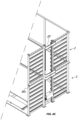
- the automated storage unit 1 comprises a support structure 10, a plurality of containers or support planes 4 for storing the products and means for the displacement of the latter.
- the automated storage unit 1 may include containers and support planes or only support planes for the products to be stored, without departing from the scope of protection of the attached claims.
- the support structure 10 consists of metal sections and the container can be made of metal material.
- the containers 4 may have an essentially longitudinal extension, so as to define an axis Z'.
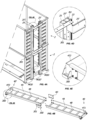
- the support structure 10 may comprise two or more upright elements 2, substantially equal to each other, with vertical extension defining respective mutually facing planes ⁇ 1 , substantially parallel and mutually connected, for example, by means of reinforcement crosspieces 3, preferably arranged at the upper end of the reinforcement elements 2 and preferably they extend horizontally.
- the upright elements 2 can be fixed directly to the ground, or, preferably, they can be further connected by base sections 1', the latter being suitable to be fixed to the ground for example by means of suitable brackets.
- Bracing and/or further connection sections may also be present between the upright elements 2, without departing from the scope of protection of the attached claims.
- Each upright element 2 may include structural sections 25, which may be substantially vertical, and support crosspieces 20, 20'; 200, 200', which may define respective axes Y1, Y3 which may be substantially horizontal.
- the crosspieces 20, 20'; 200, 200' can all be substantially parallel to each other and mutually superimposed, so that the seats 20, 20' define a plane ⁇ 2 and the seats 200, 200' define a plane ⁇ 3 .
- the planes ⁇ 2 and ⁇ 3 may face each other and be substantially parallel to each other, and they may be substantially perpendicular to the plane ⁇ 1 defined by the upright elements 2.
- the crosspieces 20, 20'; 200, 200' can preferably be aligned, so that the relative axes Y1, Y3 can coincide.
- each upright element 2 can also include a single column of crosspieces, i.e. only the crosspieces 20, 20' or only the crosspieces 200, 200', without departing from the scope of protection of the attached claims.
- Each of the support crosspieces 20; 200 can cooperate with the corresponding opposite support crosspiece 20'; 200' for supporting a respective container 4 at the respective opposite ends 40, 40'.
- Each seat 22, 22' can be defined by a respective pair of opposite support crosspieces 20, 20'; 200, 200', so that the containers 4 can be supported by the crosspieces 20, 20'; 200, 200' exclusively at the opposite ends 40, 40' thereof.
- each container 4 is provided at the ends 40, 40' with wheels R, slidable on the crosspieces 20, 20'; 200, 200'.
- the upright elements 2 can be obtained by coupling the structural sections 25 and the support crosspieces 20, 20'; 200, 200' by means of removable fixing means, such as for example screws or bolts 300 inserted into special holes 301.
- each module MOD which include two structural sections 25 and several crosspieces 20, 20'; 200, 200' and/or one or more modules MOD' which include two structural sections 25 provided with rack 23 and guide PC and a motor-driven carriage SV.
- the structural sections 25 can be replaced with longer or shorter sections. This allows to vary the storage capacity of the storage unit 1, increasing or decreasing the height thereof whenever needed.
- the structural sections 25 may be configured to be coupled to other structural sections 25 by means of removable fixing means, such as for example screws or bolts.
- each of the upright elements 2, which may for example have the crosspieces 20, 20'; 200, 200' welded or removably fixed to the structural sections 25, may comprise at least one of the end zones, and preferably both end zones, which can be mutually removably connected with at least one other corresponding upright element 2, like in the embodiment of FIG. 4A .
- each upright element 2 will define an actual module.
- the base sections 1' and/or the reinforcement crosspieces 3 can be coupled to the upright elements 2 by means of removable fixing means, for example screws or bolts, as shown for example in FIG. 5 .
- the base sections 1' and/or the reinforcement crosspieces 3 could for example be replaced with sections and/or crosspieces that are longer or shorter, or the sections and/or the crosspieces could be extended by joining two or more sets of predetermined length so that each base section or reinforcement crosspiece defines a module.
- the support structure 10 consists of metal sections connected to each other in a removable manner, so that the support structure 10 is modular and it is possible to vary the dimensions thereof in length, width and height, as illustrated above.
- the support structure 10 may further include, in a per se known manner, safety panels 5 on the sides and upper closing elements 3S. Should the dimensions of the support structure vary, these components may vary - whenever needed - preferably in a modular manner.
- containers 4 of greater or lesser length may be used, depending on the needs.
- each container 4 may advantageously include a support frame and a pair of end heads 4T1, 4T2 mutually connected to each other by means of first removable fixing means.
- the support frame can be replaced with a longer or shorter support frame, or the support frame can be extended by joining two or more sets of predetermined length so that each support frame defines a module.
- the support frame may consist of a pair of side sections 4A connected to each other by a plurality of crosspieces 4B, in a removable manner.
- the container can be left without a bottom, as shown in FIG. 7 , or a plate acting as a bottom can be inserted thereinto.
- each side section 4A will define an actual module, which can be connected to other modules by means of brackets 4D.
- the configuration mentioned above makes the container particularly light and strong at the same time.
- the displacement means may be susceptible to displace each container 4 between an inoperative position which it takes when it is in the respective storage seat 22, 22' and a working position of the products spaced from the latter.
- the automated storage unit 1 may further comprise a working bay 6.
- the working bay 6 can be an integral part of a track system 6'.
- the displacement means comprises a pair of first displacement units 255, 255' and preferably a pair of cond displacement units 250, 250' in the embodiments in which the working bay 6 is present
- the first displacement units 255, 255' will displace the containers 4 between the inoperative position and an operative position, while the second displacement units will displace the containers 4 between the operative position and the working position on the working bay 6.
- the first displacement units 255, 255' will displace the containers 4 between the inoperative position and an operative position which will coincide with the working position.
- the container 4 can be arranged in one of the seats 22, 22', left suitably empty, or it can remain on the first displacement units 255, 255' so as to allow one or more operators to pick up the contents thereof or to transport it to another zone.
- the working bay 6 may include a support frame with a pair of opposite support crosspieces 21, 21' defining respective axes Y2, Y2' substantially parallel to each other and to axes Y1, Y1'.
- the opposite support crosspieces 21, 21' can cooperate with each other to support the respective container 4 at the respective opposite ends 40, 40' when it is in the working position.
- each container 4 can suitably be supported in the inoperative and working positions exclusively by the respective first support crosspieces 20, 20'; 200, 200' and 21, 21', at the relative opposite ends 40, 40'.
- the working bay 6 can be arranged laterally to the plane ⁇ 2 or ⁇ 3 , with the main extension axis thereof substantially parallel to the latter.
- the working bay 6 will be described hereinafter arranged laterally to the plane ⁇ 2 , it is clear that it can be arranged laterally to the plane ⁇ 3 or that the storage unit 1 can include two working bays 6 arranged laterally to both the planes ⁇ 2 and ⁇ 3 , without departing from the scope of protection of the attached claims.
- the support crosspieces 200, 200' adjacent thereto may be designated to receive the containers 4 in the operative position.
- the corresponding seat 22' can be left empty, i.e. without containers 4, so as to define the operative position.
- the support crosspieces 200, 200' adjacent to the working bay 6 can be advantageously aligned with the support crosspieces 21, 21', so that the axes Y3, Y3' and the axes Y2, Y2' coincide.
- the container 4 can be displaced by translation along the coincident axes mentioned above. As illustrated above, this translation will be promoted by the second displacement units, which can be integrated in the working bay 6.
- Each of the first and second displacement units can interact with a respective opposite end 40, 40' of each container 4, as better illustrated below.
- each of the first and second displacement units can be guided respectively along a substantially vertical translation direction X, X' and along a translation direction Y4, Y4', which can coincide with the axes Y3, Y3' and Y2, Y2'.
- the first and second displacement units can therefore promote the displacement of each container 4 between the inoperative and working positions passing through an intermediate transportation position.
- the first displacement units 255, 255' can promote:
- the second displacement units can promote the translation of the container 4 up to the working position along a respective axis Y4, Y4', which can be coincident with the aforementioned axes Y3, Y3' and Y2, Y2'.
- each upright element 2 can comprise guide means suitable to guide the first displacement unit along a translation direction X, X' substantially vertical and parallel to or lying on the plane ⁇ 1, ⁇ 1'.
- Said guide means may comprise at least one first rack 23 arranged on the central sections 25 defining the direction X, X' and vertical guides PC in which the wheels RU slide.
- the first displacement units 255, 255' include a respective motor-driven carriage SV, which may include pinions IN cooperating with the rack 23 to translate along the respective direction X, X'.
- the motor-driven carriage SV can be interposed between the planes ⁇ 2 , ⁇ 3 , and more particularly between the central sections 25. This allows to displace containers 4 present in both seats 22, 22'.
- Each motor-driven carriage SV includes motion promoting means capable of acting on each container 4 to displace it, as described above.
- the motion promoting means may comprise a motor-driven slide 232 and means SL for guiding the latter along a substantially horizontal translation direction, which may for example include a rack 230.
- each motor-driven slide 232 may include pinions 231 cooperating with the rack 230.
- the motor-driven slide 232 may also include gripping means acting selectively on the respective end 40, 40' of the respective container 4 to drive the latter in motion.
- FIGS. 6 , 10 and 11 show various embodiments of the gripping means, for example defined by a lever L with a wheel R, by a cam CAM or by a piston or actuator GAO.
- the gripping means may be sized and/or configured to act on the respective end 40, 40' of the respective container 4 at the lower surface 41' thereof, opposite to the upper one 41 intended to receive the products to be stored.
- said at least one first male engagement element can be designated to be engaged in a corresponding at least one second female engagement element 4C arranged on the lower surface 41' of each of the containers 4.
- the at least one second female engagement element 4C consists of an interspace between two appendages extending from the lower surface 41' of each head 4T1, 4T2, as for example illustrated in FIG. 7 .
- the gripping means can be movable between an inoperative position in which the at least one first male engagement element R, CAM', GAO' is mutually disengaged with the corresponding at least one second female engagement element 4C and a working position in which said at least one first male engagement element R, CAM', GAO' is mutually engaged with the corresponding at least one second female engagement element 4C so as to allow the displacement of the corresponding container 4 between the inoperative and working positions.
- the aforementioned male or female elements may also be inverted, i.e. the gripping means may include at least one female engagement element and the containers 4 may include at least one male engagement element, without departing from the scope of protection of the attached claims.
- the shape of the male and female engagement elements may be any, provided that it is suitable to allow the mutual engagement thereof for the purposes of driving the container during the translations along the horizontal directions and locking it during transportation along the vertical direction.
- the guide means may comprise a rack 230 engaged by pinions 231.
- the motor-driven slide may include gripping means similar to those described above.
- Embodiments of the second displacement units are for example shown in FIGS. 10 and 11 .
- control means may include a microprocessor unit AE, for example a PLC, suitably programmed to coordinate the mutual cooperation of the opposite first displacement units 255, 255' during the displacement of the containers 4 between the inoperative and operative positions and of the second opposite displacement units during the displacement of the containers 4 between the operative and working positions.
- a microprocessor unit AE for example a PLC
- the coordination will occur so that one or more of the operations carried out by the first displacement units 255, 255' are synchronised, and that is to say a movement carried out by one or more components of a displacement unit corresponds to a concordant movement carried out by one or more components of the other displacement unit.
- first and preferably second displacement units 255, 255'; 250, 250' are electronically coupled to each other by means of the control means.
- the electric motors of the first and preferably second displacement units there can be created a so-called electric axis, aimed at coupling them without physical connection.
- the electric motors MC of the motor-driven carriages SV and preferably the electric motors MA of the motor-driven slides 232 of the first and preferably second displacement units 255, 255'; 250, 250' and preferably the electric motors MB of the gripping means of the first and/or second displacement units 255, 255'; 250, 250' are electronically coupled to each other by means of an electric axis.
- the storage unit will also be lighter and easier to ship.
- the storage unit 1 can be shipped preferably by pre-assembling the upright elements 2.
Landscapes
- Engineering & Computer Science (AREA)
- Mechanical Engineering (AREA)
- Warehouses Or Storage Devices (AREA)
- Filling Or Discharging Of Gas Storage Vessels (AREA)
- Stackable Containers (AREA)
- Fittings On The Vehicle Exterior For Carrying Loads, And Devices For Holding Or Mounting Articles (AREA)
Claims (13)
- Automatisierter Lagerturm zur Lagerung von Produkten, insbesondere länglichen Produkten, umfassend:- eine Vielzahl von Behältern oder Tragebenen (4) für die zu lagernden Produkte, wobei jeder Behälter oder jede Tragebene (4) zwei gegenüberliegende Enden (40,40') umfasst;- eine Tragstruktur (10) umfassend wenigstens eine erste Vielzahl von einander überlagernden ersten Lagersitzen (22), wobei jeder erste Lagersitz (22) dazu ausgebildet ist, jeweils einen Behälter oder eine Tragebene (4) aufzunehmen;- Verlagerungsmittel (SV, 232, CAM, AE), die dazu ausgebildet sind, jeden Behälter oder jede Tragebene (4) zwischen einer Nicht-Betriebsstellung, die diese einnehmen, wenn sie sich in dem jeweils ersten Lagersitz (22) befinden, und einer Arbeitsstellung der Produkte, die von dem Letzteren beabstandet sind, zu verlagern;wobei die Tragstruktur (10) wenigstens ein Paar aufrechter Elemente (2) umfasst, die jeweils einander zugewandte Ebenen (π1, π1') umfasst, die sich im Wesentlichen parallel und miteinander verbunden erstrecken, wobei jedes aufrechte Element (2) wenigstens eine erste Vielzahl von überlagerten Trag-Querstücken (20,20') umfasst, die jeweils erste Achsen (Y1, Y1') definieren, welche sich im Wesentlichen parallel zu oder in den ersten Ebenen (π1, π1') erstrecken, wobei jedes der ersten Trag-Querstücke (20) mit dem zugehörigen gegenüberliegenden ersten Trag-Querstück (20') zusammenwirkt, um jeweils einen Behälter oder eine Tragebene (4) an den jeweiligen gegenüberliegenden Enden (40,40') zu unterstützen, wobei jeder der Lagersitze (22) jeweils durch ein Paar von gegenüberliegenden ersten Trag-Querstücken (20,20') definiert ist;wobei die Verlagerungsmittel (SV, 232, CAM, AE) wenigstens ein erstes Paar von ersten Verlagerungseinheiten (255,255') umfassen, von denen jede dazu ausgebildet ist, mit einem jeweils gegenüberliegenden Ende (40,40') eines jeden Behälters oder einer jeden Tragebene (4) zusammenzuwirken, um diese zwischen der Nicht-Betriebsstellung und einer Betriebsstellung zu verlagern, die mit der Arbeitsstellung übereinstimmt oder von dieser beabstandet ist, wobei die Verlagerungsmittel (SV, 232, CAM, AE) weiterhin Steuerungsmittel (AE) umfassen, die wenigstens auf die ersten Verlagerungseinheiten (255,255') wirken, um das Zusammenwirken derselben während der Verlagerung des Behälters oder der Tragebene (4) zwischen der Nicht-Betriebsstellung und der Betriebsstellung zu steuern;wobei jedes aufrechte Element (2) wenigsten eine jeweils erste Verlagerungseinheit (SV, 232) und jeweilige erste Führungsmittel (23, PC) derselben entlang einer ersten Verlagerungsrichtung (X, X') umfasst, die sich im Wesentlichen parallel zu oder in der jeweiligen ersten Ebene (π1, π1') und im Wesentlichen senkrecht zu einer jeweiligen ersten Achse (Y1, Y1') erstreckt;dadurch gekennzeichnet, dass:- Die Steuerungsmittel (AE) dazu ausgebildet sind, auf jede erste Verlagerungseinheit (SV, 323, CAM) zu wirken, um eine zweite Verlagerung jedes Behälters oder jeder Tragebene (4) zwischen den Transport- und Betriebsstellungen entlang einer zweiten Verlagerungsrichtung zu bewirken, die sich im Wesentlichen parallel zu oder in der ersten Achse (Y1, Y1') und im Wesentlichen senkrecht zu der ersten Verlagerungsrichtung (X, X') erstreckt;- keine physikalische Verbindung zwischen den ersten Verlagerungseinheiten (255,255') besteht, sodass die ersten Verlagerungseinheiten (255,255') physikalisch entkoppelt sind;- jede der ersten Verlagerungseinheiten (255,255') einen jeweils motorangetriebenen Wagen (SV) umfasst, der entlang der jeweils ersten Verlagerungsrichtung (X, X') bewegbar ist, wobei der motorangetriebene Wagen (SV) erste, eine Bewegung vermittelnde Mittel (232, SL) umfasst, die dazu ausgebildet sind, auf jeden Behälter oder jede Tragebene (4) einzuwirken, um diese entlang der jeweiligen ersten Achse (Y1, Y1') jeweils entlang der ersten Achse (Y1, Y1') und der zweiten Verlagerungsrichtung zu verlagern;- jeder motorangetriebene Wagen (SV) wenigstens einen jeweils ersten elektrischen Motor (MC) umfasst, die Steuerungsmittel (AE) dazu ausgebildet sind, die ersten elektrischen Motoren (MC) der motorangetriebenen Wagen (SV) mittels einer elektrischen Achse zu koppeln;- wenigstens die Tragstruktur (10) aus Metall Abschnitten besteht, die miteinander lösbar verbunden sind.
- Automatisierte Lagereinheit nach Anspruch 1, bei welcher die Steuerungsmittel (AE) dazu ausgebildet sind, auf jede erste Verlagerungseinheit (SV, 232, CAM) zu wirken, um die Verlagerung eines jeden Behälters oder einer jeden Tragebene (4) zwischen der Nicht-Betriebsstellung und der Betriebsstellung durch eine Zwischen-Transportstellung zu bewirken, in welcher der Behälter oder die Tragebene (4) entlang der ersten Verlagerungsrichtung (X, X') über die ersten Verlagerungseinheiten (255,255') transportiert wird.
- Automatisierte Lagereinheit nach dem vorhergehenden Anspruch, bei welcher die Steuerungsmittel (AE) ausgebildet sind, um auf jede erste Verlagerungseinheit (SV, 232, CAM) zu wirken, um eine erste Verlagerung jedes Behälters oder jeder Tragebene (4) zwischen der Nicht-Betriebsstellung und Verlagerungsstellungen entlang einer jeweiligen ersten Achse (Y1, Y1') zu bewirken.
- Automatisierte Lagereinheit nach einem oder mehreren der vorhergehenden Ansprüche, bei welcher die ersten eine Bewegung vermittelnde Mittel (232, SL), einen ersten motorangetriebenen Schlitten (232) und zweite Führungsmittel (230, SL) für die Letzteren entlang einer dritten Verlagerung (Y3, Y3') umfassen, wobei der erste motorangetriebene Schlitten (232) erste Greifermittel (L, CAM, GAG) umfasst, die jeweils selektiv auf die jeweiligen Enden (40,40') der jeweiligen Behälter oder Tragebene (4) wirken, um Letzte in Bewegung zu versetzen.
- Automatisierte Lagereinheit nach einem oder mehreren der vorhergehenden Ansprüche, weiterhin umfassend eine Arbeitsbucht (6), wobei jeder Behälter oder jede Transportebene (4) sich in der Arbeitsposition befindet, wenn diese sich in der Arbeitsbucht (6) befindet, wobei die Verlagerungsmittel (SV, 232, AE) weiterhin ein Paar zweite Verlagerungseinheiten (250,250') umfasst, die jeweils ausgebildet sind, um jeweils mit einem gegenüberliegenden Ende (40,40') eines jeden Behälters oder einer Tragebene (4) zusammenzuwirken, um diese zwischen einer Betriebsstellung und der Arbeitsstellung zu verlagern, wobei die Steuerungsmittel (AE) auch auf die zweiten Verlagerungseinheiten (250,250') wirken, um das gegenseitige Zusammenwirken derselben während der Verlagerung der Behälter oder der Tragebene (4) zwischen der Betriebs- und Arbeitsstellung zu steuern.
- Automatisierte Lagereinheit nach dem vorhergehenden Anspruch, bei welcher die zweiten Verlagerungseinheiten (250,250'), ein zweiter motorangetriebener Schlitten (232) und dritte Führungsmittel (230, SL) der Letzteren entlang einer vierten Verlagerungsrichtung (Y4, Y4') im Wesentlichen senkrecht bezüglich der ersten Verlagerungsrichtung (X, X'), wobei der motorangetriebene Schlitten (232) zweite Greifermittel (L, CAM, GAG) umfasst, die selektiv auf die jeweiligen Enden (40,40') des jeweiligen Behälters oder der jeweiligen Tragebene (4) wirken, um diese entlang der vierten Verlagerungsrichtung (Y4, Y4') anzutreiben.
- Automatisierte Lagereinheit nach einem der vorhergehenden Ansprüche, bei welcher jeder Behälter oder jede Tragebene (4) eine obere Fläche (41) aufweist, die dazu ausgebildet ist, die zu lagernden Produkte aufzunehmen, und weiterhin eine gegenüberliegende untere Fläche (41 A) aufweist, wobei die ersten und/oder zweiten Greifermittel (L, CAM, GAG) so bemessen und/oder konfiguriert sind, dass sie auf die jeweiligen Enden (40,40') der jeweiligen Behälter oder Tragebene (4) an deren unteren Fläche (41') einwirken können.
- Automatisierte Lagereinheit nach dem vorhergehenden Anspruch, bei welcher die ersten und/oder zweiten Greifermittel (L, CAM, GAG) wenigstens ein erstes männliches oder weibliches Eingriffselement (R, CAM', GAO') aufweisen, welches zum Eingriff mit wenigstens einem zweiten männlichen oder weiblichen Eingriffselement (4C) ausgebildet ist, das an der unteren Fläche (41 ') jedes Behälters oder jeder Tragebene (4) angeordnet ist.
- Automatisierte Lagereinheit nach dem vorhergehenden Anspruch, bei welcher die ersten und/oder zweiten Greifermittel (L, CAM, GAO) zwischen einer Nicht-Betriebsstellung, in welcher die ersten oder zweiten weiblichen oder männlichen Eingriffselemente (R, CAM', GAO') sich jeweils in Eingriff mit den entsprechenden wenigstens einen zweiten weiblichen oder männlichen Eingriffselementen (4C) befinden und einer Arbeitsstellung, in welcher wenigstens ein erstes männliches oder weibliches Eingriffselement (R, CAM', GAO') jeweils mit dem entsprechenden wenigstens einen zweiten weiblichen oder männlichen Eingriffselement (4C) zusammenwirkt, um eine Verlagerung des entsprechenden Behälters oder der Tragebene (4) zwischen der Nicht-Betriebsstellung und der Arbeitsstellung zu erlauben.
- Automatisierte Lagereinheit nach einem oder mehreren der vorhergehenden Ansprüche, bei welcher die Tragstruktur (10) wenigstens ein Paar von Basisabschnitten (1) und verstärkte Querstücke (3) umfasst, die jeweils vierte Achsen (Z) definieren, welche sich im Wesentlichen senkrecht zu den ersten Ebenen (π1, π1') erstrecken, die an gegenüberliegenden Seiten relativ zu den aufrechten Elementen (2), Basisabschnitten (1), Verstärkungs - Querstücken (3) und aufrechten Elementen (2) angeordnet sind, die gegenseitig mittels erster lösbarer Befestigungsmittel verbunden sind.
- Automatisierte Lagereinheit nach einem oder mehreren der vorhergehenden Ansprüche, wobei die aufrechten Elemente (2) Strukturabschnitte umfassen, die sich im Wesentlichen parallel zu der ersten Verlagerungsrichtung (X, X') erstrecken wobei die letzteren und die 1. Trag-Querstücke (20,20') miteinander mittels zweiter lösbarer Befestigungsmittel verbunden sind.
- Automatisierte Lagereinheit nach einem oder mehreren der vorhergehenden Ansprüche, wobei jedes der aufrechten Elemente (2) jeweils wenigstens eines der Endbereiche umfasst, die jeweils lösbar mit wenigstens einem anderen entsprechenden aufrechten Element (2) verbunden sind.
- Verfahren, welches mittels eines Prozessors zur Steuerung der ersten (SV, 232) und zweiten Verlagerungseinheiten (250,250') einer automatisierten Lagereinheit zur Verlagerung eines Behälters oder eine Tragebene (4) zwischen Nicht-Betriebsstellung und Arbeitsstellungen implementiert ist, wobei die automatisierte Lagereinheit gemäß einem oder mehrerer der vorstehenden Ansprüche ausgebildet ist, soweit diese von den Ansprüchen 4 und 6 abhängig ist, wobei:• im Falle einer Verlagerung des Behälters oder der Tragebene (4) von der Nicht-Betriebsstellung in die Arbeitsstellung das Verfahren folgende Schritte umfasst:a) Ineingriffbringen des Behälters oder der Tragebene (4) mittels erster Greifermittel (L, CAM, GAG);b) Verlagerung des Behälters oder der Transportebene (4) aus der Nicht-Betriebsstellung in die Transportstellung jeweils entlang einer ersten Achse (Y1, Y1') durch die ersten motorangetriebenen Schlitten (232);c) Verlagerung des Behälters oder der Tragebene (4) in die Transportstellung entlang der ersten Verlagerungsrichtung (X, X') durch die motorangetriebenen Wagen (SV);d) Verlagerung der Behälter oder Tragebene (4) aus der Transportstellung in die Betriebsstellung entlang der zweiten Verlagerungsrichtung (Y1, Y1 `) mittels der ersten motorangetriebenen Schlitten (232);e) Außereingriffbringen des Behälters oder der Tragebene (4) durch die zweiten Greifermittel (L, CAM, GAG);f) Ineingriffbringen der Behälter oder der Tragebene (4) mittels der zweiten Greifermittel (L, CAM, GAG);g) Verlagerung der Behälter oder Tragebene (4) von der Betriebsstellung in die Arbeitsstellung entlang der zweiten Verlagerungsrichtung (Y1, Y1') durch die zweiten motorangetriebenen Schlitten (250,250');h) Außereingriffbringen der Behälter oder der Tragebene (4) mittels der zweiten Greifermittel (L, CAM, GAG);• im Falle der Verlagerung der Behälter oder der Tragebene (4) von der Arbeitsstellung in die Nicht-Betriebsstellung umfasst das Verfahren die Schritte h) und a) in umgekehrter Reihenfolge, wobei die Schritte des Ineingriffbringens und Außereingriffbringens entgegengesetzt sind.
Applications Claiming Priority (2)
| Application Number | Priority Date | Filing Date | Title |
|---|---|---|---|
| IT102019000015971A IT201900015971A1 (it) | 2019-09-11 | 2019-09-11 | Torre multipiano smontabile e componibile con contenitori sovrapposti in verticale e contrapposti trasversalmente e tra loro mobili per prodotti lungiformi |
| PCT/IB2020/052228 WO2021048639A1 (en) | 2019-09-11 | 2020-03-12 | Automated storage tower for storing products, in particular longitudinal products |
Publications (3)
| Publication Number | Publication Date |
|---|---|
| EP4028341A1 EP4028341A1 (de) | 2022-07-20 |
| EP4028341C0 EP4028341C0 (de) | 2024-07-17 |
| EP4028341B1 true EP4028341B1 (de) | 2024-07-17 |
Family
ID=69811468
Family Applications (1)
| Application Number | Title | Priority Date | Filing Date |
|---|---|---|---|
| EP20728181.7A Active EP4028341B1 (de) | 2019-09-11 | 2020-03-12 | Automatisierter lagerturm zum lagern von produkten, insbesondere von länglichen produkten |
Country Status (3)
| Country | Link |
|---|---|
| EP (1) | EP4028341B1 (de) |
| IT (1) | IT201900015971A1 (de) |
| WO (1) | WO2021048639A1 (de) |
Families Citing this family (1)
| Publication number | Priority date | Publication date | Assignee | Title |
|---|---|---|---|---|
| IT202100006821A1 (it) * | 2021-03-22 | 2022-09-22 | Gatta S R L | Cassetto per un magazzino automatico |
Citations (3)
| Publication number | Priority date | Publication date | Assignee | Title |
|---|---|---|---|---|
| FR2451874A1 (fr) * | 1979-03-21 | 1980-10-17 | Remmert Friedrich Gmbh | Magasin a rayonnages, en particulier pour l'entreposage de produits allonges |
| DE20304872U1 (de) * | 2003-03-25 | 2004-04-29 | Megamat GmbH Büro + Lagertechnik | Antriebseinrichtung für eine Lagervorrichtung |
| DE202006018793U1 (de) * | 2006-12-11 | 2008-01-24 | Megamat GmbH Büro- und Lagertechnik | Lagervorrichtung |
Family Cites Families (1)
| Publication number | Priority date | Publication date | Assignee | Title |
|---|---|---|---|---|
| DE20105582U1 (de) * | 2001-03-23 | 2002-08-01 | Bellheimer Metallwerk GmbH, 76756 Bellheim | Lagerlift |
-
2019
- 2019-09-11 IT IT102019000015971A patent/IT201900015971A1/it unknown
-
2020
- 2020-03-12 WO PCT/IB2020/052228 patent/WO2021048639A1/en not_active Ceased
- 2020-03-12 EP EP20728181.7A patent/EP4028341B1/de active Active
Patent Citations (3)
| Publication number | Priority date | Publication date | Assignee | Title |
|---|---|---|---|---|
| FR2451874A1 (fr) * | 1979-03-21 | 1980-10-17 | Remmert Friedrich Gmbh | Magasin a rayonnages, en particulier pour l'entreposage de produits allonges |
| DE20304872U1 (de) * | 2003-03-25 | 2004-04-29 | Megamat GmbH Büro + Lagertechnik | Antriebseinrichtung für eine Lagervorrichtung |
| DE202006018793U1 (de) * | 2006-12-11 | 2008-01-24 | Megamat GmbH Büro- und Lagertechnik | Lagervorrichtung |
Also Published As
| Publication number | Publication date |
|---|---|
| EP4028341C0 (de) | 2024-07-17 |
| IT201900015971A1 (it) | 2021-03-11 |
| WO2021048639A1 (en) | 2021-03-18 |
| EP4028341A1 (de) | 2022-07-20 |
Similar Documents
| Publication | Publication Date | Title |
|---|---|---|
| KR102663009B1 (ko) | 모듈형 보관 시스템 및 방법 | |
| EP2526032B2 (de) | Shuttle für ein automatisiertes lagerhaus | |
| KR102848223B1 (ko) | 개선된 용량을 가진 저장 랙 | |
| EP4028341B1 (de) | Automatisierter lagerturm zum lagern von produkten, insbesondere von länglichen produkten | |
| US8960455B2 (en) | Mobile industrial rack system | |
| AU2015318768B2 (en) | Modular base for forming installations and method for storage by means of stacking and movement of cases | |
| AU2019334906B2 (en) | Autonomous vehicle, such as an automated guided vehicle or an autonomous mobile robot | |
| EP4457160A1 (de) | Modulares lagersystem, verfahren zum aufbau eines lagersystems und verfahren zur lagerung | |
| EP1695928B1 (de) | Vorrichtung zum Transport von einzelnen und geschichten Scheibenprodukten | |
| CN120858063A (zh) | 托盘切换系统和传送器 | |
| US7588409B2 (en) | Modular assembly for manufacturing structures for support and powered translation of forks in lift trucks | |
| CN210028811U (zh) | 水平存储转运系统 | |
| CN112938372A (zh) | Agv系统的对接物料架 | |
| WO1996005049A1 (en) | Transfer press | |
| EP3469952A1 (de) | Trägervorrichtung für fässer | |
| CN115215080A (zh) | 步进式条筒双向输送机 | |
| RU2273587C1 (ru) | Тележка для транспортировки и стыковки блоков | |
| JPS63123710A (ja) | シヤトル式搬送装置 | |
| US4934047A (en) | Assembly machine | |
| CN207631905U (zh) | 智能轨道输送装置 | |
| WO2022139574A1 (en) | A pallet spacing assembly for use in a cargo space of a vehicle, a lateral support frame and a kit of parts | |
| EP4477577B1 (de) | Verpackungssystem und verfahren für den transport von palettenhubwagen | |
| CN223146646U (zh) | 一种叉车支板的钻孔夹具 | |
| CN219928832U (zh) | 一种钢筋网扶正运输装置 | |
| EP1231162A1 (de) | Transfervorrichtung |
Legal Events
| Date | Code | Title | Description |
|---|---|---|---|
| STAA | Information on the status of an ep patent application or granted ep patent |
Free format text: STATUS: UNKNOWN |
|
| STAA | Information on the status of an ep patent application or granted ep patent |
Free format text: STATUS: THE INTERNATIONAL PUBLICATION HAS BEEN MADE |
|
| PUAI | Public reference made under article 153(3) epc to a published international application that has entered the european phase |
Free format text: ORIGINAL CODE: 0009012 |
|
| STAA | Information on the status of an ep patent application or granted ep patent |
Free format text: STATUS: REQUEST FOR EXAMINATION WAS MADE |
|
| 17P | Request for examination filed |
Effective date: 20220411 |
|
| AK | Designated contracting states |
Kind code of ref document: A1 Designated state(s): AL AT BE BG CH CY CZ DE DK EE ES FI FR GB GR HR HU IE IS IT LI LT LU LV MC MK MT NL NO PL PT RO RS SE SI SK SM TR |
|
| DAV | Request for validation of the european patent (deleted) | ||
| DAX | Request for extension of the european patent (deleted) | ||
| RAP3 | Party data changed (applicant data changed or rights of an application transferred) |
Owner name: PIAZZA, ANTONIO Owner name: PIAZZA, MARCO |
|
| GRAP | Despatch of communication of intention to grant a patent |
Free format text: ORIGINAL CODE: EPIDOSNIGR1 |
|
| STAA | Information on the status of an ep patent application or granted ep patent |
Free format text: STATUS: GRANT OF PATENT IS INTENDED |
|
| INTG | Intention to grant announced |
Effective date: 20240415 |
|
| GRAS | Grant fee paid |
Free format text: ORIGINAL CODE: EPIDOSNIGR3 |
|
| GRAA | (expected) grant |
Free format text: ORIGINAL CODE: 0009210 |
|
| STAA | Information on the status of an ep patent application or granted ep patent |
Free format text: STATUS: THE PATENT HAS BEEN GRANTED |
|
| AK | Designated contracting states |
Kind code of ref document: B1 Designated state(s): AL AT BE BG CH CY CZ DE DK EE ES FI FR GB GR HR HU IE IS IT LI LT LU LV MC MK MT NL NO PL PT RO RS SE SI SK SM TR |
|
| REG | Reference to a national code |
Ref country code: CH Ref legal event code: EP |
|
| REG | Reference to a national code |
Ref country code: DE Ref legal event code: R096 Ref document number: 602020034109 Country of ref document: DE |
|
| REG | Reference to a national code |
Ref country code: IE Ref legal event code: FG4D |
|
| U01 | Request for unitary effect filed |
Effective date: 20240801 |
|
| U07 | Unitary effect registered |
Designated state(s): AT BE BG DE DK EE FI FR IT LT LU LV MT NL PT RO SE SI Effective date: 20240909 |
|
| PG25 | Lapsed in a contracting state [announced via postgrant information from national office to epo] |
Ref country code: NO Free format text: LAPSE BECAUSE OF FAILURE TO SUBMIT A TRANSLATION OF THE DESCRIPTION OR TO PAY THE FEE WITHIN THE PRESCRIBED TIME-LIMIT Effective date: 20241017 |
|
| PG25 | Lapsed in a contracting state [announced via postgrant information from national office to epo] |
Ref country code: PL Free format text: LAPSE BECAUSE OF FAILURE TO SUBMIT A TRANSLATION OF THE DESCRIPTION OR TO PAY THE FEE WITHIN THE PRESCRIBED TIME-LIMIT Effective date: 20240717 Ref country code: GR Free format text: LAPSE BECAUSE OF FAILURE TO SUBMIT A TRANSLATION OF THE DESCRIPTION OR TO PAY THE FEE WITHIN THE PRESCRIBED TIME-LIMIT Effective date: 20241018 |
|
| PG25 | Lapsed in a contracting state [announced via postgrant information from national office to epo] |
Ref country code: IS Free format text: LAPSE BECAUSE OF FAILURE TO SUBMIT A TRANSLATION OF THE DESCRIPTION OR TO PAY THE FEE WITHIN THE PRESCRIBED TIME-LIMIT Effective date: 20241117 |
|
| PG25 | Lapsed in a contracting state [announced via postgrant information from national office to epo] |
Ref country code: HR Free format text: LAPSE BECAUSE OF FAILURE TO SUBMIT A TRANSLATION OF THE DESCRIPTION OR TO PAY THE FEE WITHIN THE PRESCRIBED TIME-LIMIT Effective date: 20240717 |
|
| PG25 | Lapsed in a contracting state [announced via postgrant information from national office to epo] |
Ref country code: ES Free format text: LAPSE BECAUSE OF FAILURE TO SUBMIT A TRANSLATION OF THE DESCRIPTION OR TO PAY THE FEE WITHIN THE PRESCRIBED TIME-LIMIT Effective date: 20240717 Ref country code: RS Free format text: LAPSE BECAUSE OF FAILURE TO SUBMIT A TRANSLATION OF THE DESCRIPTION OR TO PAY THE FEE WITHIN THE PRESCRIBED TIME-LIMIT Effective date: 20241017 |
|
| PG25 | Lapsed in a contracting state [announced via postgrant information from national office to epo] |
Ref country code: RS Free format text: LAPSE BECAUSE OF FAILURE TO SUBMIT A TRANSLATION OF THE DESCRIPTION OR TO PAY THE FEE WITHIN THE PRESCRIBED TIME-LIMIT Effective date: 20241017 Ref country code: PL Free format text: LAPSE BECAUSE OF FAILURE TO SUBMIT A TRANSLATION OF THE DESCRIPTION OR TO PAY THE FEE WITHIN THE PRESCRIBED TIME-LIMIT Effective date: 20240717 Ref country code: NO Free format text: LAPSE BECAUSE OF FAILURE TO SUBMIT A TRANSLATION OF THE DESCRIPTION OR TO PAY THE FEE WITHIN THE PRESCRIBED TIME-LIMIT Effective date: 20241017 Ref country code: IS Free format text: LAPSE BECAUSE OF FAILURE TO SUBMIT A TRANSLATION OF THE DESCRIPTION OR TO PAY THE FEE WITHIN THE PRESCRIBED TIME-LIMIT Effective date: 20241117 Ref country code: HR Free format text: LAPSE BECAUSE OF FAILURE TO SUBMIT A TRANSLATION OF THE DESCRIPTION OR TO PAY THE FEE WITHIN THE PRESCRIBED TIME-LIMIT Effective date: 20240717 Ref country code: GR Free format text: LAPSE BECAUSE OF FAILURE TO SUBMIT A TRANSLATION OF THE DESCRIPTION OR TO PAY THE FEE WITHIN THE PRESCRIBED TIME-LIMIT Effective date: 20241018 Ref country code: ES Free format text: LAPSE BECAUSE OF FAILURE TO SUBMIT A TRANSLATION OF THE DESCRIPTION OR TO PAY THE FEE WITHIN THE PRESCRIBED TIME-LIMIT Effective date: 20240717 |
|
| PG25 | Lapsed in a contracting state [announced via postgrant information from national office to epo] |
Ref country code: SM Free format text: LAPSE BECAUSE OF FAILURE TO SUBMIT A TRANSLATION OF THE DESCRIPTION OR TO PAY THE FEE WITHIN THE PRESCRIBED TIME-LIMIT Effective date: 20240717 |
|
| U20 | Renewal fee for the european patent with unitary effect paid |
Year of fee payment: 6 Effective date: 20250317 |
|
| PG25 | Lapsed in a contracting state [announced via postgrant information from national office to epo] |
Ref country code: CZ Free format text: LAPSE BECAUSE OF FAILURE TO SUBMIT A TRANSLATION OF THE DESCRIPTION OR TO PAY THE FEE WITHIN THE PRESCRIBED TIME-LIMIT Effective date: 20240717 |
|
| PG25 | Lapsed in a contracting state [announced via postgrant information from national office to epo] |
Ref country code: SK Free format text: LAPSE BECAUSE OF FAILURE TO SUBMIT A TRANSLATION OF THE DESCRIPTION OR TO PAY THE FEE WITHIN THE PRESCRIBED TIME-LIMIT Effective date: 20240717 |
|
| PLBE | No opposition filed within time limit |
Free format text: ORIGINAL CODE: 0009261 |
|
| STAA | Information on the status of an ep patent application or granted ep patent |
Free format text: STATUS: NO OPPOSITION FILED WITHIN TIME LIMIT |
|
| 26N | No opposition filed |
Effective date: 20250422 |
|
| PG25 | Lapsed in a contracting state [announced via postgrant information from national office to epo] |
Ref country code: MC Free format text: LAPSE BECAUSE OF FAILURE TO SUBMIT A TRANSLATION OF THE DESCRIPTION OR TO PAY THE FEE WITHIN THE PRESCRIBED TIME-LIMIT Effective date: 20240717 |
|
| REG | Reference to a national code |
Ref country code: CH Ref legal event code: H13 Free format text: ST27 STATUS EVENT CODE: U-0-0-H10-H13 (AS PROVIDED BY THE NATIONAL OFFICE) Effective date: 20251023 |
|
| GBPC | Gb: european patent ceased through non-payment of renewal fee |
Effective date: 20250312 |
|
| PG25 | Lapsed in a contracting state [announced via postgrant information from national office to epo] |
Ref country code: GB Free format text: LAPSE BECAUSE OF NON-PAYMENT OF DUE FEES Effective date: 20250312 |
|
| PG25 | Lapsed in a contracting state [announced via postgrant information from national office to epo] |
Ref country code: CH Free format text: LAPSE BECAUSE OF NON-PAYMENT OF DUE FEES Effective date: 20250331 |
|
| PG25 | Lapsed in a contracting state [announced via postgrant information from national office to epo] |
Ref country code: IE Free format text: LAPSE BECAUSE OF NON-PAYMENT OF DUE FEES Effective date: 20250312 |