EP4028617B1 - Loquet de porte, verrou et mécanisme d'ouverture pour système de traitement de dispositif médical - Google Patents
Loquet de porte, verrou et mécanisme d'ouverture pour système de traitement de dispositif médical Download PDFInfo
- Publication number
- EP4028617B1 EP4028617B1 EP20771409.8A EP20771409A EP4028617B1 EP 4028617 B1 EP4028617 B1 EP 4028617B1 EP 20771409 A EP20771409 A EP 20771409A EP 4028617 B1 EP4028617 B1 EP 4028617B1
- Authority
- EP
- European Patent Office
- Prior art keywords
- lever
- door
- medical device
- treatment machine
- actuator
- Prior art date
- Legal status (The legal status is an assumption and is not a legal conclusion. Google has not performed a legal analysis and makes no representation as to the accuracy of the status listed.)
- Active
Links
Images



Classifications
-
- A—HUMAN NECESSITIES
- A61—MEDICAL OR VETERINARY SCIENCE; HYGIENE
- A61L—METHODS OR APPARATUS FOR STERILISING MATERIALS OR OBJECTS IN GENERAL; DISINFECTION, STERILISATION OR DEODORISATION OF AIR; CHEMICAL ASPECTS OF BANDAGES, DRESSINGS, ABSORBENT PADS OR SURGICAL ARTICLES; MATERIALS FOR BANDAGES, DRESSINGS, ABSORBENT PADS OR SURGICAL ARTICLES
- A61L2/00—Disinfection or sterilisation of materials or objects, in general; Accessories therefor
- A61L2/24—Apparatus using programmed or automatic operation
-
- E—FIXED CONSTRUCTIONS
- E05—LOCKS; KEYS; WINDOW OR DOOR FITTINGS; SAFES
- E05B—LOCKS; ACCESSORIES THEREFOR; HANDCUFFS
- E05B57/00—Locks in which a pivoted latch is used also as locking means
-
- A—HUMAN NECESSITIES
- A61—MEDICAL OR VETERINARY SCIENCE; HYGIENE
- A61B—DIAGNOSIS; SURGERY; IDENTIFICATION
- A61B90/00—Instruments, implements or accessories specially adapted for surgery or diagnosis and not covered by any of the groups A61B1/00 - A61B50/00, e.g. for luxation treatment or for protecting wound edges
- A61B90/70—Cleaning devices specially adapted for surgical instruments
-
- A—HUMAN NECESSITIES
- A61—MEDICAL OR VETERINARY SCIENCE; HYGIENE
- A61L—METHODS OR APPARATUS FOR STERILISING MATERIALS OR OBJECTS IN GENERAL; DISINFECTION, STERILISATION OR DEODORISATION OF AIR; CHEMICAL ASPECTS OF BANDAGES, DRESSINGS, ABSORBENT PADS OR SURGICAL ARTICLES; MATERIALS FOR BANDAGES, DRESSINGS, ABSORBENT PADS OR SURGICAL ARTICLES
- A61L2/00—Disinfection or sterilisation of materials or objects, in general; Accessories therefor
- A61L2/26—Accessories
-
- E—FIXED CONSTRUCTIONS
- E05—LOCKS; KEYS; WINDOW OR DOOR FITTINGS; SAFES
- E05B—LOCKS; ACCESSORIES THEREFOR; HANDCUFFS
- E05B17/00—Accessories in connection with locks
- E05B17/0025—Devices for forcing the wing firmly against its seat or to initiate the opening of the wing
- E05B17/0033—Devices for forcing the wing firmly against its seat or to initiate the opening of the wing for opening only
-
- E—FIXED CONSTRUCTIONS
- E05—LOCKS; KEYS; WINDOW OR DOOR FITTINGS; SAFES
- E05B—LOCKS; ACCESSORIES THEREFOR; HANDCUFFS
- E05B47/00—Operating or controlling locks or other fastening devices by electric or magnetic means
- E05B47/0001—Operating or controlling locks or other fastening devices by electric or magnetic means with electric actuators; Constructional features thereof
- E05B47/0002—Operating or controlling locks or other fastening devices by electric or magnetic means with electric actuators; Constructional features thereof with electromagnets
- E05B47/0003—Operating or controlling locks or other fastening devices by electric or magnetic means with electric actuators; Constructional features thereof with electromagnets having a movable core
- E05B47/0004—Operating or controlling locks or other fastening devices by electric or magnetic means with electric actuators; Constructional features thereof with electromagnets having a movable core said core being linearly movable
-
- E—FIXED CONSTRUCTIONS
- E05—LOCKS; KEYS; WINDOW OR DOOR FITTINGS; SAFES
- E05B—LOCKS; ACCESSORIES THEREFOR; HANDCUFFS
- E05B47/00—Operating or controlling locks or other fastening devices by electric or magnetic means
- E05B47/02—Movement of the bolt by electromagnetic means; Adaptation of locks, latches, or parts thereof, for movement of the bolt by electromagnetic means
-
- E—FIXED CONSTRUCTIONS
- E05—LOCKS; KEYS; WINDOW OR DOOR FITTINGS; SAFES
- E05B—LOCKS; ACCESSORIES THEREFOR; HANDCUFFS
- E05B47/00—Operating or controlling locks or other fastening devices by electric or magnetic means
- E05B47/02—Movement of the bolt by electromagnetic means; Adaptation of locks, latches, or parts thereof, for movement of the bolt by electromagnetic means
- E05B47/023—Movement of the bolt by electromagnetic means; Adaptation of locks, latches, or parts thereof, for movement of the bolt by electromagnetic means the bolt moving pivotally or rotatively
-
- E—FIXED CONSTRUCTIONS
- E05—LOCKS; KEYS; WINDOW OR DOOR FITTINGS; SAFES
- E05B—LOCKS; ACCESSORIES THEREFOR; HANDCUFFS
- E05B47/00—Operating or controlling locks or other fastening devices by electric or magnetic means
- E05B47/06—Controlling mechanically-operated bolts by electro-magnetically-operated detents
- E05B47/0607—Controlling mechanically-operated bolts by electro-magnetically-operated detents the detent moving pivotally or rotatively
-
- E—FIXED CONSTRUCTIONS
- E05—LOCKS; KEYS; WINDOW OR DOOR FITTINGS; SAFES
- E05C—BOLTS OR FASTENING DEVICES FOR WINGS, SPECIALLY FOR DOORS OR WINDOWS
- E05C3/00—Fastening devices with bolts moving pivotally or rotatively
- E05C3/12—Fastening devices with bolts moving pivotally or rotatively with latching action
- E05C3/124—Fastening devices with bolts moving pivotally or rotatively with latching action with latch under compression force between its pivot and the striker
-
- E—FIXED CONSTRUCTIONS
- E05—LOCKS; KEYS; WINDOW OR DOOR FITTINGS; SAFES
- E05F—DEVICES FOR MOVING WINGS INTO OPEN OR CLOSED POSITION; CHECKS FOR WINGS; WING FITTINGS NOT OTHERWISE PROVIDED FOR, CONCERNED WITH THE FUNCTIONING OF THE WING
- E05F15/00—Power-operated mechanisms for wings
- E05F15/70—Power-operated mechanisms for wings with automatic actuation
- E05F15/73—Power-operated mechanisms for wings with automatic actuation responsive to movement or presence of persons or objects
-
- A—HUMAN NECESSITIES
- A61—MEDICAL OR VETERINARY SCIENCE; HYGIENE
- A61L—METHODS OR APPARATUS FOR STERILISING MATERIALS OR OBJECTS IN GENERAL; DISINFECTION, STERILISATION OR DEODORISATION OF AIR; CHEMICAL ASPECTS OF BANDAGES, DRESSINGS, ABSORBENT PADS OR SURGICAL ARTICLES; MATERIALS FOR BANDAGES, DRESSINGS, ABSORBENT PADS OR SURGICAL ARTICLES
- A61L2103/00—Materials or objects being the target of disinfection or sterilisation
- A61L2103/05—Living organisms or biological materials
-
- A—HUMAN NECESSITIES
- A61—MEDICAL OR VETERINARY SCIENCE; HYGIENE
- A61L—METHODS OR APPARATUS FOR STERILISING MATERIALS OR OBJECTS IN GENERAL; DISINFECTION, STERILISATION OR DEODORISATION OF AIR; CHEMICAL ASPECTS OF BANDAGES, DRESSINGS, ABSORBENT PADS OR SURGICAL ARTICLES; MATERIALS FOR BANDAGES, DRESSINGS, ABSORBENT PADS OR SURGICAL ARTICLES
- A61L2103/00—Materials or objects being the target of disinfection or sterilisation
- A61L2103/15—Laboratory, medical or dentistry appliances, e.g. catheters or sharps
-
- A—HUMAN NECESSITIES
- A61—MEDICAL OR VETERINARY SCIENCE; HYGIENE
- A61L—METHODS OR APPARATUS FOR STERILISING MATERIALS OR OBJECTS IN GENERAL; DISINFECTION, STERILISATION OR DEODORISATION OF AIR; CHEMICAL ASPECTS OF BANDAGES, DRESSINGS, ABSORBENT PADS OR SURGICAL ARTICLES; MATERIALS FOR BANDAGES, DRESSINGS, ABSORBENT PADS OR SURGICAL ARTICLES
- A61L2202/00—Aspects relating to methods or apparatus for disinfecting or sterilising materials or objects
- A61L2202/10—Apparatus features
- A61L2202/12—Apparatus for isolating biocidal substances from the environment
- A61L2202/121—Sealings, e.g. doors, covers, valves, sluices
-
- A—HUMAN NECESSITIES
- A61—MEDICAL OR VETERINARY SCIENCE; HYGIENE
- A61L—METHODS OR APPARATUS FOR STERILISING MATERIALS OR OBJECTS IN GENERAL; DISINFECTION, STERILISATION OR DEODORISATION OF AIR; CHEMICAL ASPECTS OF BANDAGES, DRESSINGS, ABSORBENT PADS OR SURGICAL ARTICLES; MATERIALS FOR BANDAGES, DRESSINGS, ABSORBENT PADS OR SURGICAL ARTICLES
- A61L2202/00—Aspects relating to methods or apparatus for disinfecting or sterilising materials or objects
- A61L2202/10—Apparatus features
- A61L2202/12—Apparatus for isolating biocidal substances from the environment
- A61L2202/122—Chambers for sterilisation
-
- A—HUMAN NECESSITIES
- A61—MEDICAL OR VETERINARY SCIENCE; HYGIENE
- A61L—METHODS OR APPARATUS FOR STERILISING MATERIALS OR OBJECTS IN GENERAL; DISINFECTION, STERILISATION OR DEODORISATION OF AIR; CHEMICAL ASPECTS OF BANDAGES, DRESSINGS, ABSORBENT PADS OR SURGICAL ARTICLES; MATERIALS FOR BANDAGES, DRESSINGS, ABSORBENT PADS OR SURGICAL ARTICLES
- A61L2202/00—Aspects relating to methods or apparatus for disinfecting or sterilising materials or objects
- A61L2202/10—Apparatus features
- A61L2202/14—Means for controlling sterilisation processes, data processing, presentation and storage means, e.g. sensors, controllers, programs
-
- A—HUMAN NECESSITIES
- A61—MEDICAL OR VETERINARY SCIENCE; HYGIENE
- A61L—METHODS OR APPARATUS FOR STERILISING MATERIALS OR OBJECTS IN GENERAL; DISINFECTION, STERILISATION OR DEODORISATION OF AIR; CHEMICAL ASPECTS OF BANDAGES, DRESSINGS, ABSORBENT PADS OR SURGICAL ARTICLES; MATERIALS FOR BANDAGES, DRESSINGS, ABSORBENT PADS OR SURGICAL ARTICLES
- A61L2202/00—Aspects relating to methods or apparatus for disinfecting or sterilising materials or objects
- A61L2202/10—Apparatus features
- A61L2202/17—Combination with washing or cleaning means
-
- E—FIXED CONSTRUCTIONS
- E05—LOCKS; KEYS; WINDOW OR DOOR FITTINGS; SAFES
- E05B—LOCKS; ACCESSORIES THEREFOR; HANDCUFFS
- E05B17/00—Accessories in connection with locks
- E05B17/0079—Locks with audio features
- E05B17/0083—Sound emitting devices, e.g. loudspeakers
-
- E—FIXED CONSTRUCTIONS
- E05—LOCKS; KEYS; WINDOW OR DOOR FITTINGS; SAFES
- E05B—LOCKS; ACCESSORIES THEREFOR; HANDCUFFS
- E05B17/00—Accessories in connection with locks
- E05B17/20—Means independent of the locking mechanism for preventing unauthorised opening, e.g. for securing the bolt in the fastening position
- E05B17/2084—Means to prevent forced opening by attack, tampering or jimmying
-
- E—FIXED CONSTRUCTIONS
- E05—LOCKS; KEYS; WINDOW OR DOOR FITTINGS; SAFES
- E05B—LOCKS; ACCESSORIES THEREFOR; HANDCUFFS
- E05B17/00—Accessories in connection with locks
- E05B17/22—Means for operating or controlling lock or fastening device accessories, i.e. other than the fastening members, e.g. switches, indicators
-
- E—FIXED CONSTRUCTIONS
- E05—LOCKS; KEYS; WINDOW OR DOOR FITTINGS; SAFES
- E05B—LOCKS; ACCESSORIES THEREFOR; HANDCUFFS
- E05B47/00—Operating or controlling locks or other fastening devices by electric or magnetic means
- E05B47/0001—Operating or controlling locks or other fastening devices by electric or magnetic means with electric actuators; Constructional features thereof
- E05B47/0002—Operating or controlling locks or other fastening devices by electric or magnetic means with electric actuators; Constructional features thereof with electromagnets
- E05B2047/0007—Operating or controlling locks or other fastening devices by electric or magnetic means with electric actuators; Constructional features thereof with electromagnets with two or more electromagnets
-
- E—FIXED CONSTRUCTIONS
- E05—LOCKS; KEYS; WINDOW OR DOOR FITTINGS; SAFES
- E05B—LOCKS; ACCESSORIES THEREFOR; HANDCUFFS
- E05B47/00—Operating or controlling locks or other fastening devices by electric or magnetic means
- E05B47/0001—Operating or controlling locks or other fastening devices by electric or magnetic means with electric actuators; Constructional features thereof
- E05B2047/0014—Constructional features of actuators or power transmissions therefor
- E05B2047/0018—Details of actuator transmissions
- E05B2047/0024—Cams
-
- E—FIXED CONSTRUCTIONS
- E05—LOCKS; KEYS; WINDOW OR DOOR FITTINGS; SAFES
- E05B—LOCKS; ACCESSORIES THEREFOR; HANDCUFFS
- E05B47/00—Operating or controlling locks or other fastening devices by electric or magnetic means
- E05B47/0001—Operating or controlling locks or other fastening devices by electric or magnetic means with electric actuators; Constructional features thereof
- E05B2047/0014—Constructional features of actuators or power transmissions therefor
- E05B2047/0037—Powered actuators with automatic return to the neutral position by non-powered means, e.g. springs
-
- E—FIXED CONSTRUCTIONS
- E05—LOCKS; KEYS; WINDOW OR DOOR FITTINGS; SAFES
- E05B—LOCKS; ACCESSORIES THEREFOR; HANDCUFFS
- E05B47/00—Operating or controlling locks or other fastening devices by electric or magnetic means
- E05B2047/0048—Circuits, feeding, monitoring
- E05B2047/005—Opening, closing of the circuit
- E05B2047/0056—Opening, closing of the circuit by sensing the presence of a person, e.g. body heat sensor
-
- E—FIXED CONSTRUCTIONS
- E05—LOCKS; KEYS; WINDOW OR DOOR FITTINGS; SAFES
- E05B—LOCKS; ACCESSORIES THEREFOR; HANDCUFFS
- E05B47/00—Operating or controlling locks or other fastening devices by electric or magnetic means
- E05B2047/0048—Circuits, feeding, monitoring
- E05B2047/0067—Monitoring
- E05B2047/0069—Monitoring bolt position
-
- E—FIXED CONSTRUCTIONS
- E05—LOCKS; KEYS; WINDOW OR DOOR FITTINGS; SAFES
- E05B—LOCKS; ACCESSORIES THEREFOR; HANDCUFFS
- E05B47/00—Operating or controlling locks or other fastening devices by electric or magnetic means
- E05B2047/0072—Operation
- E05B2047/0073—Current to unlock only
-
- E—FIXED CONSTRUCTIONS
- E05—LOCKS; KEYS; WINDOW OR DOOR FITTINGS; SAFES
- E05B—LOCKS; ACCESSORIES THEREFOR; HANDCUFFS
- E05B47/00—Operating or controlling locks or other fastening devices by electric or magnetic means
- E05B2047/0094—Mechanical aspects of remotely controlled locks
-
- E—FIXED CONSTRUCTIONS
- E05—LOCKS; KEYS; WINDOW OR DOOR FITTINGS; SAFES
- E05B—LOCKS; ACCESSORIES THEREFOR; HANDCUFFS
- E05B41/00—Locks with visible indication as to whether the lock is locked or unlocked
-
- E—FIXED CONSTRUCTIONS
- E05—LOCKS; KEYS; WINDOW OR DOOR FITTINGS; SAFES
- E05B—LOCKS; ACCESSORIES THEREFOR; HANDCUFFS
- E05B43/00—Time locks
- E05B43/005—Timer devices controlling electrically operated locks
-
- E—FIXED CONSTRUCTIONS
- E05—LOCKS; KEYS; WINDOW OR DOOR FITTINGS; SAFES
- E05B—LOCKS; ACCESSORIES THEREFOR; HANDCUFFS
- E05B47/00—Operating or controlling locks or other fastening devices by electric or magnetic means
- E05B47/0046—Electric or magnetic means in the striker or on the frame; Operating or controlling the striker plate
-
- E—FIXED CONSTRUCTIONS
- E05—LOCKS; KEYS; WINDOW OR DOOR FITTINGS; SAFES
- E05B—LOCKS; ACCESSORIES THEREFOR; HANDCUFFS
- E05B63/00—Locks or fastenings with special structural characteristics
- E05B63/0056—Locks with adjustable or exchangeable lock parts
-
- E—FIXED CONSTRUCTIONS
- E05—LOCKS; KEYS; WINDOW OR DOOR FITTINGS; SAFES
- E05B—LOCKS; ACCESSORIES THEREFOR; HANDCUFFS
- E05B63/00—Locks or fastenings with special structural characteristics
- E05B63/06—Locks or fastenings with special structural characteristics with lengthwise-adjustable bolts ; with adjustable backset, i.e. distance from door edge
-
- E—FIXED CONSTRUCTIONS
- E05—LOCKS; KEYS; WINDOW OR DOOR FITTINGS; SAFES
- E05B—LOCKS; ACCESSORIES THEREFOR; HANDCUFFS
- E05B9/00—Lock casings or latch-mechanism casings ; Fastening locks or fasteners or parts thereof to the wing
- E05B9/02—Casings of latch-bolt or deadbolt locks
-
- E—FIXED CONSTRUCTIONS
- E05—LOCKS; KEYS; WINDOW OR DOOR FITTINGS; SAFES
- E05Y—INDEXING SCHEME ASSOCIATED WITH SUBCLASSES E05D AND E05F, RELATING TO CONSTRUCTION ELEMENTS, ELECTRIC CONTROL, POWER SUPPLY, POWER SIGNAL OR TRANSMISSION, USER INTERFACES, MOUNTING OR COUPLING, DETAILS, ACCESSORIES, AUXILIARY OPERATIONS NOT OTHERWISE PROVIDED FOR, APPLICATION THEREOF
- E05Y2400/00—Electronic control; Electrical power; Power supply; Power or signal transmission; User interfaces
- E05Y2400/80—User interfaces
- E05Y2400/85—User input means
- E05Y2400/856—Actuation thereof
- E05Y2400/858—Actuation thereof by body parts, e.g. by feet
-
- E—FIXED CONSTRUCTIONS
- E05—LOCKS; KEYS; WINDOW OR DOOR FITTINGS; SAFES
- E05Y—INDEXING SCHEME ASSOCIATED WITH SUBCLASSES E05D AND E05F, RELATING TO CONSTRUCTION ELEMENTS, ELECTRIC CONTROL, POWER SUPPLY, POWER SIGNAL OR TRANSMISSION, USER INTERFACES, MOUNTING OR COUPLING, DETAILS, ACCESSORIES, AUXILIARY OPERATIONS NOT OTHERWISE PROVIDED FOR, APPLICATION THEREOF
- E05Y2999/00—Subject-matter not otherwise provided for in this subclass
Definitions
- the technology of the present invention relates generally to medical device treatment systems, and more particularly to methods and mechanisms for latching, locking and opening a door or lid of such medical device treatment systems.
- WDS disinfectors or sterilizers
- Conventional medical device treatment systems such as washers, disinfectors or sterilizers (WDS) are available to wash, disinfect and/or sterilize medical devices, but are not capable of disinfecting or sterilizing their own exterior surfaces.
- WDS doors and/or lids may trap and harbor harmful or toxic contaminants and/or germs when an operator manually opens or closes the door and/or lid to load or unload medical devices into or out from the WDS. Accordingly, hands-free operation of WDS doors and/or lids is advantageous in the medical device industry to prevent such contamination.
- Typical hands-free operation may therefore include automatic door latching, locking, opening and/or closing.
- these operations require two or more independent mechanisms to control door latching, locking, opening or closing.
- some conventional medical device treatment systems have mechanisms that open or close the door, but require a separate mechanism to latch or lock the door.
- conventional assemblies are generally quite complex and expensive and are typically too large for installation in smaller WDS's.
- EP 1405967 A1 relates to a closing device in particular for a steam-sterilizing machine.
- the device can be used to close any container that is put under pressure during its use and for which a closure of maximum safety is required, such as steam-sterilizing machines employed to sterilize instruments and equipment for dental use.
- a medical device treatment machine comprising: a treatment chamber for washing, disinfecting, and/or sterilizing a medical device, a door hingedly attached to the treatment chamber and moveable between an open position, to expose the treatment chamber, and a closed position, to seal the treatment chamber, wherein the door comprises a latch pin on a first side of the door, and a latch and lock assembly fixed to a wall of the treatment chamber, wherein the latch and lock assembly comprises: a lever pivotable between a latched position and an unlatched position, wherein in the latched position, the lever engages the latch pin to prevent movement of the door from the closed position to the open position, and wherein in the unlatched position, the lever disengages the latch pin to allow movement of the door from the closed position to the open position, and a first actuator.
- the present disclosure therefore, relates to a medical device treatment system including a door latch, lock and open mechanism having automatic and manual door opening features, all fully integrated into one assembly.
- the door latch, lock and open mechanism assembly provides enough adjustability to handle manufacturing tolerances, while also retaining the adjustment throughout its service life.
- the medical device treatment system may include one or more of the following features: 1) a single mechanism that can latch, lock and open a medical device treatment system door, 2) a hands-free, foot-operated control mechanism to detect when the operator wishes to open the door automatically, and 3) a forced-entry prevention mechanism to ensure the operator cannot open the door using excessive physical force when the door is closed, latched and locked.
- the invention relates to a medical device treatment machine comprising a treatment chamber for washing, disinfecting, and/or sterilizing a medical device and a door hingedly attached to the treatment chamber.
- the door is moveable between an open position, to expose the treatment chamber, and a closed position, to seal the treatment chamber.
- the door includes a latch pin on a first side of the door.
- the medical device treatment machine also includes a latch and lock assembly.
- the latch and lock assembly includes a lever pivotable between a latched position and an unlatched position.
- the latch and lock assembly also includes a first actuator configured to selectively move a locking tab between a locked position and an unlocked position. In the locked position, the locking tab is configured to block pivotable movement of the lever from the latched position to the unlatched position.
- the latch and lock assembly further includes a second actuator configured to selectively rotate a door opening tab between a first position and a second position when the locking tab is in the unlocked position.
- a second actuator configured to selectively rotate a door opening tab between a first position and a second position when the locking tab is in the unlocked position.
- Embodiments of the invention may include one or more of the following additional features separately or in combination, according to the appended claims.
- the locking tab may operate on a first side of the lever and the door opening tab may operate on a second side of the lever, opposing the first side of the lever.
- the locking tab in the locked position, may abut a portion of the lever, and in the unlocked position, the locking tab may be spaced apart from the lever.
- the latch and lock assembly may include a lever biasing member configured to bias the lever toward the latched position.
- the lever biasing member may be a spring.
- first actuator and the second actuator may be pull-type solenoids.
- the latch and lock assembly may include a fixed housing to which at least one of the lever, first actuator, locking tab, second actuator, door opening tab and lever biasing member are mounted.
- the latch and lock assembly may include an adjustable housing to which the fixed housing is adjustably attached.
- the latch and lock assembly may include an alignment rod passing through a wall of the fixed housing and a wall of the adjustable housing to align the fixed housing relative to the adjustable housing.
- the latch and lock assembly may include an adjustment tuner passing through a wall of the fixed housing and a wall of the adjustable housing.
- the adjustment tuner may include a threaded bolt and associated jam nut, which, when tightened, prevent movement of the fixed housing relative to the adjustment housing.
- the latch and lock assembly may include a door opening tab adjusting block mounted to the fixed housing and including a screw.
- the door opening tab adjusting block may be configured to adjust the position of the door opening tab within the fixed housing relative to the lever.
- the latch and lock assembly may include a switch configured to detect whether and when the locking tab is in a locked position or an unlocked position.
- the medical device treatment machine may include a hinge on a second side of the door opposite the first side of the door.
- the hinge of the door may comprise a hinge biasing member for biasing the door toward an open position to automatically move the door from the closed position to the open position when the lever is in the unlatched position.
- the medical device treatment machine may include a stop pin extending from the chamber, and a stop block fixed to the door.
- the stop block may include a roller pin extending from the stop block in a direction configured to be perpendicular to the stop pin when the door is in a closed position.
- the roller pin When the door is in a closed position, the roller pin may slidably abut the stop pin to permit a lateral movement of the door between the closed position and the open position and block a vertical movement of the door in a direction perpendicular to the lateral movement of the door.
- the medical device treatment machine may include a sensing apparatus for detecting a presence and removal of a foot of an operator in a sensing zone of the sensing apparatus.
- the medical device treatment machine may also include a controller for controlling the operations of the second actuator according to the detection of the presence and removal of the foot of the operator in the sensing zone of the sensing apparatus.
- the controller may be configured to receive a foot-presence signal from the sensing apparatus when the sensing apparatus detects the presence of the foot of the operator in the sensing zone of the sensing apparatus.
- the controller may also be configured to send an activation signal to an indicator apparatus on the medical device treatment machine to activate the indicator apparatus and receive a foot-removal signal from the sensing apparatus when the foot sensor detects the removal of the foot of the operator from the sensing zone of the sensing apparatus.
- the controller may also be configured to send an unlatch signal to the second actuator to rotate the door opening tab in abutting contact with the lever to pivot the lever from the latched position to the unlatched position.
- the controller may be configured to send the unlatch signal to the second actuator a predetermined period of time after receipt of the foot-removal signal.
- the invention also relates to a method of operating a medical device treatment machine.
- the method includes rotating, by the second actuator, a door opening tab of the latch and lock assembly that is in abutting contact with a lever to pivot the lever from a latched position to an unlatched position.
- Embodiments of the invention may include one or more of the following additional features separately or in combination, according to the appended claims.
- the method may include the steps of detecting, by a sensing apparatus disposed on the medical device treatment machine, the presence of a foot of an operator in a sensing zone of the sensing apparatus; receiving, by a controller of the medical device treatment machine, a foot-presence signal from the sensing apparatus, and sending, by the controller, an activation signal to an indicator apparatus on the medical device treatment machine to activate the indicator apparatus; detecting, by the sensing apparatus, the removal of the foot of the operator from the sensing zone of the sensing apparatus and receiving, by the controller, a foot-removal signal from the sensing apparatus; sending, by the controller, an unlatch signal to an actuator of a latch and lock assembly of the medical device treatment machine.
- the unlatch signal may be sent to the actuator a predetermined period of time after receipt of the foot-removal signal.
- the method may include automatically moving a door of the medical device treatment machine from a closed position to an open position via a biasing force on a hinge of the door by a hinge biasing member.
- a medical device treatment system such as a medical device treatment machine 10 is generally depicted.
- the medical device treatment machine 10 may be, for example, a machine for washing, disinfecting and/or sterilizing a medical device, such as surgical tools or any other medical device requiring washing, disinfecting and/or sterilization before and/or after use.
- the medical device treatment machine 10 includes a treatment chamber 12 for washing, disinfecting and/or sterilizing the medical device.
- the medical device treatment machine 10 also includes a door 14 hingedly attached to the treatment chamber 12. The door 14 may be automatically and/or manually moveable between a closed position, depicted in Fig. 1a , and an open position, depicted in Fig. 1b .
- the treatment chamber 12 In the closed position of the door 14, the treatment chamber 12 is closed off from the exterior of the medical device treatment machine 10 and may be sealed shut for operation of the medical device treatment machine 10. In the open position of the door 14, the treatment chamber 12 is exposed to the exterior of the medical device treatment machine 10 for insertion or removal of medical devices into or out from the treatment chamber 12.
- the door 14 includes a latch pin 16 on a first side 20 of the door 14 and a hinge 18 on a second side 22 of the door 14, opposite the first side 20.
- the hinge 18 may include a hinge biasing member 18a that imparts a biasing force on the door 14 toward the open position.
- the door 14 may be automatically opened with the aid of the hinge biasing member 18a under certain conditions, as will later be described in detail.
- the medical device treatment machine 10 may include a forced entry prevention mechanism, indicated generally at 80, and a hands-free, foot-operated automatic opening mechanism, indicated generally at 90, both of which will later be described with detailed reference to Figs. 5 and 6 , respectively.
- the medical device treatment machine 10 includes a latch and lock assembly 30 for latching/unlatching and locking/unlocking the door 14.
- the latch and lock assembly 30 may be mounted to a side wall of the treatment chamber 12 associated with the first side 20 of the door 14 having the latch pin 16, as shown, or otherwise disposed between the latch pin 16 of the door 14 and the treatment chamber 12 of the medical device treatment machine 10.
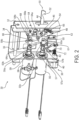
- the latch and lock assembly 30 includes an adjustment assembly 32 and a fixed assembly 34, adjustably connected to each other with an alignment rod 36 and an adjustment tuner 38.
- the adjustment assembly 32 may be installed directly onto the side wall of the treatment chamber 12, while the fixed assembly 34 may be arranged within the boundaries of, and adjustably mounted to, the adjustment assembly 32.
- Various other components of the latch and lock assembly 30 may therefore be mounted to and/or disposed within the boundaries of the fixed assembly 34.
- the adjustment assembly 32 and the fixed assembly 34 are adjustably connected relative to one another by the alignment rod 36 at an upper end and the adjustment tuner 38 at the lower end.
- the alignment rod 36 and the adjustment tuner 38 provide adjustability to the latch and lock assembly 30 to account for any manufacturing tolerances involved in the latch and lock assembly 30 or its integration/installation into the medical device treatment machine 10.
- the alignment rod 36 may be a cylindrical rod that aligns the fixed assembly 34 relative to the adjustment assembly 32 and allows for fast and simple adjustment and movement of the fixed assembly 34 to accommodate for any manufacturing tolerances or desired adjustments for a particular application. As illustrated, the alignment rod 36 passes through at least one wall of the fixed assembly 34 and at least one wall of the adjustment assembly 32 and the adjustment tuner 38 similarly passes through at least one wall of the fixed assembly 34 and at least one wall of the adjustment assembly 32.
- the adjustment tuner 38 may include a threaded bolt 40 having an associated jam nut 42 configured to move the fixed assembly 34 linearly inwards or outwards relative to the adjustment assembly 32 (to the right and left in Figs. 2 - 4 ).
- the alignment rod 36 ensures proper linear alignment when the fixed assembly 34 is moved relative to the adjustment assembly 32.
- the associated jam nut 42 when tightened down after adjustment, prevents rotation of the adjustment tuner 38 and therefore secures the position of the fixed assembly 34 and any of the components within and/or mounted to the fixed assembly 34 relative to the adjustment assembly 32, to prevent any undesired relative movement or adjustment.
- the alignment rod 36 and adjustment tuner 38 may therefore provide both adjustability to and security of the position of the latch and lock assembly 30 throughout its entire service life.
- the latch and lock assembly 30 includes a lever 44 pivotably fixed to the fixed assembly 34 by means of a pivot fastener 46 (or other pivot means including a pivot pin, hinge, or bearing, among others), with an actuation end 48 of the lever 44 on one side of the pivot fastener 46 and a latching end 50 of the lever 44 on the opposite side of the pivot fastener 46.
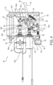
- the lever 44 is pivotable about its pivot fastener 46 between a latched position, depicted in Figs. 2 and 3 , and an unlatched position, depicted in Fig. 4 .
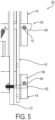
- the lever 44 includes an open-hook recess 52 near or at an end of the latching end 50 of the lever 44 that engages the latch pin 16 of the door 14 when the door 14 is in the closed position and the lever 44 is in the latched position, as shown for example in Fig. 5 .
- the fixed assembly 34 and adjustment assembly 32 include openings through which the lever 44 extends, such that the open hook recess 52 portion of the lever 44 extends to and is therefore engageable with the latch pin 16 of the door 14 when the door 14 is in a closed position.
- the latch and lock assembly 30 may also include a lever biasing member 54 attached to the fixed assembly 34 and lever 44 in a manner to bias the lever 44 toward the latched position.
- the lever biasing member 54 may be a tension spring, as shown, or any other type of biasing means.
- the illustrated latch and lock assembly 30 has a dual actuator configuration, comprising a first actuator 56 and a second actuator 58 that selectively and cooperatively control the position of the lever 44 of the latch and lock assembly 30.
- the first actuator 56 and second actuator 58 may be, for example, solenoids.
- the first actuator 56 and the second actuator 58 are pull-type solenoids, wherein in their unactuated state, their respective actuation rods 57 and 59 are extended due to a spring force exerted by respective springs 57a and 59a of the actuators 56 and 58, and when actuated, their actuation rods 57 and 59 are retracted against the spring force of the springs 57a and 59a, thereby retracting the respective actuation rods 57 and 59 and thus pulling the components to which the actuation rods 57 and 59 are respectively connected.
- push-type solenoids and/or other suitable actuators are contemplated.
- the actuators may be driven electrically and/or pneumatically, for example, and may have any suitable arrangement including for example in-line, as shown, belt driven or gear driven, among others.
- the first actuator 56 selectively moves a locking tab 60 by rotatable connection to the locking tab 60.
- the locking tab 60 has a pivot end 60a at one end, an abutment end 60b at an opposite end, and a coupling aperture 60c therebetween.
- the pivot end 60a is rotatably mounted to the fixed assembly 34 via a pivot fastener 61 (or other pivot means including a pivot pin, hinge, or bearing, among others).
- the actuation rod 57 of the first actuator 56 is rotatably coupled to the locking tab 60 at the coupling aperture 60c via a pin 57b. Extension and retraction of the actuation rod 57 is linear and the coupling aperture 60c may be configured as a vertical slot to compensate for linear movement of the actuation rod 57.
- Extension of the actuation rod 57 translates into clockwise pivotable movement of the locking tab 60 about the pivot fastener 61, which, in turn, urges the abutment end 60b of the locking tab 60 into an abutment position relative to, in the illustrative embodiment below, a first side 62 (lower side, as shown) of the actuation end 48 of the lever 44.
- Retraction of the actuation rod 57 as by energization of the actuator 56 overcoming the force exerted by spring 57a, translates into counterclockwise pivotable movement of the locking tab 60 about the pivot fastener 61, which, in turn, urges the abutment end 60b of the locking tab 60 out of an abutment position relative to, in the illustrative embodiment out from below, the first side 62 of the actuation end 48 of the lever 44.
- the first actuator 56 is thus configured to selectively rotate, or move, the locking tab 60 between a locked position, depicted in Fig. 2 , and an unlocked position, depicted in Figs. 3 and 4 .
- the locking tab 60 in the locked position, is positioned directly next to the lever 44 on the first side 62 of the lever 44, in abutting contact with at least a portion of the lever 44 at the actuation end 48 of the lever 44.
- the abutment end 60b of the locking tab 60 obstructs the path of movement of the actuation end 48 of the lever 44, and thus physically blocks pivotable movement of the lever 44 from the lever's latched position to the lever's unlatched position.
- the abutment end 60b of the locking tab 60 does not obstruct the path of movement of the actuation end 48 of the lever 44, and instead is spaced wholly apart from the lever 44, that is out of the way of the actuation end 48 of the lever 44, thereby allowing pivotable movement of the lever 44 from the lever's latched position to the lever's unlatched position.
- the second actuator 58 selectively moves a door opening tab 64 by rotatable connection to the door opening tab 64.
- the door opening tab 64 takes the form of a cam, it being appreciated that other forms are possible and contemplated herein.
- the door opening tab 64 has a pivot end 64a at one end, a coupling aperture 64b at an opposite end, and a cam segment 64c laterally offset from the pivot end 64a and the coupling aperture 64b, in the illustrative embodiment laterally offset from a line connecting the pivot end 64a and the coupling aperture 64b.
- the door opening tab 64 has an L-shape configuration with the coupling aperture 64b at the end of one leg of the L, the cam segment 64c at the end of the other leg of the L, and the pivot end 64a at the junction of the legs of the L.
- the pivot end 64a is rotatably mounted to the fixed assembly 34 via a pivot fastener 65 (or other pivot means including a pivot pin, hinge, or bearing, among others).
- the actuation rod 59 of the second actuator 58 is rotatably coupled to the door opening tab 64 at the coupling aperture 64b via a pin 59b.
- Extension and retraction of the actuation rod 59 is linear and the coupling aperture 64b may be configured as a vertical slot to compensate for linear movement of the actuation rod 59.
- Extension of the actuation rod 59 as by spring biasing force, translates into clockwise pivotable movement of the door opening tab 64 about the pivot fastener 65, which, in turn, urges the cam segment 64c of the door opening tab 64 into a first adjacent position relative to, in the illustrative embodiment above, a second side 66 of the actuation end 48 of the lever 44.
- the cam segment 64c of the door opening tab 64 enables the lever 44 to be rotated clockwise about the pivot fastener 46, as by the lever biasing member 54, such that the first side 62 of the actuation end 48 of the lever 44 is in an out of the way position to enable the locking tab 60 to be rotated clockwise to a position in which the abutment end 60b thereof is underneath the first side 62 thereby obstructing the path of movement of the actuation end 48 and locking the lever 44 into the latched position.
- the second side 66 i.e. upper side in the illustrative embodiment, of the actuation end 48 of the lever 44 may abut the cam segment 64c, as shown, although this need not be the case and other embodiments are contemplated.
- the second side 66 of the actuation end 48 of the lever 44 may abut a structure other than the cam segment 64c, so long as the lever 44 is in an out of the way position to enable the locking tab 60 to be rotated to a locked position.
- the second side 66 of the actuation end 48 of the lever 44 may abut the coupling aperture 64b end of the door opening tab 64 or a stop member attached to or formed as part of the fixed assembly 34.
- any portion of the lever 44 not necessarily the second side 66 of the actuation end 48, may abut any other structure of the latch and lock assembly 30 to resist clockwise movement of the lever 44 about the pivot fastener 46 and thus position the lever 44 out of the path of movement of the locking tab 60 so that locking can occur.
- the central portion of the lever surrounding the pivot fastener 46 may be equipped with a radially projecting protuberance that abuts a stop member in of the latch and lock assembly 30 to resist such clockwise movement.
- FIG. 3 shows the latch and lock assembly 30 in an unlocked state, more specifically the abutment end 60b of the locking tab 60 has been moved out of the way from the actuation end 48 of the lever 44, that is, not obstructing the path of movement of the actuation end 48 of the lever 44.
- the cam segment 64c of the door opening tab 64 abuts the second side 66, in the illustrative embodiment the upper side, of the actuation end 48 of the lever 44, and urges the lever 44 counterclockwise about the pivot fastener 46, as by energization force of the actuator 58 overcoming the biasing force of the lever biasing member 54 (and the force exerted by the spring 59a), such that the open hook recess 52 near or at the latching end 50 of the lever 44 is sufficiently raised and out of the way to enable withdrawal of the latch pin 16 of the door 14, that is, to enable opening of the door 14 (automatically or manually).
- the second actuator 58 thus selectively rotates the door opening tab 64 between a first position, depicted in Figs. 2 and 3 , and a second position, depicted in Fig. 4 .
- the rotation of the door opening tab 64 by the second actuator 58 is limited by the position of the locking tab 60, described elsewhere herein.
- the second actuator 58 is configured to rotate the door opening tab 64 from the first position to the second position when the locking tab 60 is in the unlocked position, that is, when the locking tab 60 is not obstructing the path of movement of the actuation end 48 of the lever 44.
- the door opening tab 64 in both the first position and the second position, is positioned next to the actuation end 48 of the lever 44 on the second side 66 of the lever 44. In the first position, the door opening tab 64 may be in abutting contact with at least a portion of the lever 44 at the actuation end 48 of the lever 44, although this need not be the case, as described above. As the door opening tab 64 is rotated from the first position to the second position, the door opening tab 64 abuts at least a portion of the lever 44, for example at the second side 66 of the actuation end 48 thereof, to urge movement of the lever 44 about the pivot fastener 46.
- the cam segment 64c and more generally the door opening tab 64 may have a triangular or oblong shape, such that rotational movement of the door opening tab 64 from the first position to the second position imparts a downward force on the lever 44 (as viewed in Figs. 2-4 ).
- the downward force imparted on the lever 44 by the rotation of the door opening tab 64 overcomes the biasing force of the lever biasing member 54 and therefore pivots the lever 44 from the latched position to the unlatched position and disengages the open hook recess 52 of the lever 44 from the latch pin 16 of the door 14.
- Rotational movement of the door opening tab 64 from the second position to the first position relieves the overcoming downward force on the lever 44, thereby allowing the lever 44 to pivot from the unlatched position to the latched position due to the biasing force of the lever biasing member 54.
- first and second actuators 56, 58 are positioned adjacent one another and lie in the same actuator plane, and their respective rods 57, 59 likewise actuate in the same plane.
- the lever 44, the locking tab 60, and the door opening tab 64 are adjacent one another and lie in the same locking/latching plane.
- the actuator plane is laterally adjacent and parallel to the locking/latching plane, which adds to the accessibility and compactness of the design.
- the pivot fasteners 46, 61, 65, and pivot pins 57b, 59b having their respective pivot axes transverse, perpendicular in the illustrative embodiment, to the respective actuator plane and locking/latching plane.
- the latch and lock assembly 30 may include a door opening tab adjusting block 68 fixed to the fixed assembly 34 and configured to allow adjustment of the position of the door opening tab 64. Adjustment of the position of the door opening tab 64 in the first position may affect the vertical position of the lever 44 for example in embodiments where the door opening tab 64 in the first position is in abutting relation with the lever 44, for example as shown in Figs. 2 and 3 .
- the door opening tab adjusting block 68 may also therefore be configured to allow adjustment of the vertical position of the lever 44 to ensure complete engagement between the open hook recess 52 on the lever 44 and the latch pin 16 of the door 14 when the door 14 is in the closed position and the lever 44 is in the latched position.
- the door opening tab adjusting block 68 includes a tapped block having a screw 68a threaded therein that abuts the door opening tab 64 and when rotated adjusts the position of the door opening tab 64 relative to the lever 44.
- the latch and lock assembly 30 may also include a switch 70 that is electrically connected to a controller of the medical device treatment machine 10 for signaling to the controller when the latch and lock assembly 30 is in a locked or unlocked state.
- the switch 70 may be fixed to the fixed assembly 34 and may include an extending arm 72 that is actuated when the first actuator 56 moves the locking tab 60 from the locked position to the unlocked position.
- the extending arm 72 of the switch 70 is actuated and the switch 70 is configured to send an unlocked signal to the controller, signaling the unlocked state.
- the extending arm 72 of the switch 70 is not actuated and the switch 70 is configured to send a locked signal to the controller, signaling the locked state.
- the controller of the medical device treatment machine 10 actively senses whether and when the latch and lock assembly 30 is in the locked or unlocked state at any given moment.
- the latch and lock assembly 30 may therefore be in any one of: a) a locked/latched state, depicted in Fig. 2 , wherein the latch and lock assembly 30 holds the door 14 in the closed position and does not allow the door 14 to be manually or automatically moved to the open position, b) an unlocked/latched state, depicted in Fig. 3 , wherein the latch and lock assembly 30 holds the door 14 in the closed position and allows the door 14 to be manually moved to the open position for example, by manually opening the door 14 to urge the lever 44 upward (counter clockwise in Figs. 3 and 4 ) against the biasing force of the lever biasing member 54, or c) an unlocked/unlatched state, depicted in Fig.
- latch and lock assembly 30 does not hold the door 14 in the closed position and therefore allows the door 14 to be manually and/or automatically moved to the opened position.
- Which state the latch and lock assembly 30 is in at any given moment is determined by the operation of the first actuator 56 and the second actuator 58 and, therefore, the position of the lever 44 as limited and affected by the position and movement of the locking tab 60 and door opening tab 64.
- the locked/latched state is the default state of the latch and lock assembly 30, where neither the first actuator 56 nor the second actuator 58 are energized. Accordingly, in the event of a power or system shut-off during a treatment cycle of the medical device treatment machine 10, when the door 14 is in a closed position and the latch and lock assembly 30 is in the locked/latched state, the latch and lock assembly 30 will remain in the locked/latched state. In the locked/latched state, the lever 44 of the latch and lock assembly 30 is in the latched position, engaging the latch pin 16 of the door 14.
- the locking tab 60 is in the locked position, obstructing the path of movement of the actuation end 48 of the lever 44, and blocking the lever 44 from becoming unlatched (blocking the lever 44 from moving from the latched position to the unlatched position).
- the door opening tab 64 is in the first position, imparting no force (if not in abutting contact with the lever 44) or a minimal amount of force (if in abutting contact with the lever 44) on the actuation end 48 of the lever 44. Accordingly, the lever 44 is maintained in the latched position by the biasing force of the lever biasing member 54 and the blocking of pivotable movement of the lever 44 by the locking tab 60. Accordingly, in the locked/latched state of Fig. 2 , it is ensured that the door 14 of the medical device treatment machine 10 remains closed and locked and the door 14 is neither manually nor automatically moveable from the closed position to the open position.
- the latch and lock assembly 30 transitions to the unlocked/latched state, depicted in Fig. 3 .
- the locking tab 60 In the unlocked/latched state, the locking tab 60 is in the unlocked position such that the abutment end 60b of the locking tab 60 does not obstruct the path of movement of the actuation end 48 of the lever 44, and instead is spaced wholly apart from the lever 44, as moved by the first actuator 56.
- the locking tab 60 therefore, no longer blocks pivotable movement of the lever 44 from the latched position to the unlatched position.
- the biasing force of the lever biasing member 54 may be overcome by manual force and/or automatic force.
- manual operation of a door handle, pulling the door 14 and thus the latch pin 16 away from the treatment chamber 12, or the like may impart an overcoming force on the lever 44, opposite that of the biasing force of the lever biasing member 54, counterclockwise in the illustrative embodiment, thereby pivoting the lever 44 from the latched position to the unlatched position.
- the door 14 is then free to automatically move to the open position due to for example stored potential energy, gravity, spring or elastic forces or otherwise.
- the hinge biasing member of the hinge 18 may automatically push the door 14 to an open position with its stored potential energy.
- the hinge 18 may be configured to automatically push the door 14 to an open position that is only a few inches open, such that an operator may manually move the door 14 to a more open position.
- the medical device treatment machine 10 may include a forced-entry prevention mechanism 80.
- the forced-entry prevention mechanism 80 is integrated into the medical device treatment machine 10 between the treatment chamber 12 and the door 14 to ensure that an operator cannot use excessive physical force to open the door 14 of the medical device treatment machine 10 when the door 14 is in the closed position and the latch and lock assembly 30 is in a latched and locked state.
- the forced-entry prevention mechanism 80 includes a stop pin 82 fixed to the treatment chamber 12 that projects outward from the treatment chamber 12 into the vicinity of the door 14 of the medical device treatment machine 10.
- the forced-entry prevention mechanism 80 also includes a roller pin 84 fixed to the door 14 in a position aligned for abutting engagement with the stop pin 82 of the treatment chamber 12 when the door 14 is in the closed position.
- the roller pin 84 is positioned for perpendicular alignment with the stop pin 82 when the door 14 is in the closed position.
- the stop pin 82 may be a smooth projection and the roller pin 84 may be a free-rotating cylindrical roller.
- the roller pin 84 may extend from a stop block 86 that is fixed to the door 14.
- the roller pin 84 is positioned to engage the stop pin 82 on a side of the stop pin 82 that is proximal to the latch and lock assembly 30 (the upper side of the stop pin 82 in the Fig. 5 embodiment) such that when the door 14 is in the closed position, the engagement of the roller pin 84 and the stop pin 82 provides an opposing point of contact between the door 14 and the treatment chamber 12. This provides resisting mitigation to downward force that may otherwise overcome the biasing force of the lever biasing member 54 and the locking tab 60 that maintain the latch and lock assembly 30 in the latched and locked state.
- roller pin 84 is configured to slidably abut the stop pin 82 to permit pivotable movement of the door 14 between the closed position and the open position but block a vertical movement of the door 14 in a direction perpendicular to the plane of pivotable movement of the door 14 when the door 14 is in the closed position. This effectively prevents a forced opening of the door 14 when the latch and lock assembly 30 is in a latched and locked state.
- the medical device treatment machine 10 may include a foot-operated automatic door opening mechanism 90.
- the foot-operated automatic door opening mechanism 90 may be activated when the latch and lock assembly 30 is in the unlocked/latched state.
- the operator may either manually transition the latch and lock assembly 30 from the unlocked/latched state to the unlocked/unlatched state to open the door 14, or may initiate automatic transitioning of the latch and lock assembly 30 to the unlocked/unlatched state and automatic opening of the door 14 by use of the foot-operated automatic door opening mechanism 90.
- the foot-operated automatic door opening mechanism 90 may be activated when the latch and lock assembly 30 is in the locked/latched state.
- the operator may use the foot-operated automatic door opening mechanism 90 to both automatically transition the latch and lock assembly 30 from the locked/latched state to the unlocked/latched state and automatically transition the latch and lock assembly 30 from the unlocked/latched state to the unlocked/unlatched state to open the door 14.
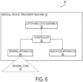
- the foot-operated automatic door opening mechanism 90 includes a sensing apparatus 94 and an indicator apparatus 98.
- the sensing apparatus 94 and the indicator apparatus 98 are configured to interface with each other, and with the latch and lock assembly 30, via a controller 92 that is configured to control the operations, and timing of the operations, of the first actuator 56 and/or the second actuator 58 of the latch and lock assembly 30.
- the sensing apparatus 94 is a proximity sensor configured to detect the presence and removal of a foot of an operator in a sensing zone 96 of the sensing apparatus 94.
- the sensing apparatus 94 may be a pedal or lever disposed in the sensing zone 96 and configured to be engaged and disengaged by a foot of an operator, which engagement and disengagement respectively provide an indication of the presence and removal of the foot of the operator in the sensing zone 96 of the sensing apparatus 94.
- the sensing apparatus 94 may be disposed near a bottom of the medical device treatment machine 10 such that the sensing zone 96 of the sensing apparatus 94, within which the sensing apparatus 94 may detect the presence and removal of the foot of the operator, is near the ground where the medical device treatment machine 10 rests.
- the operator may activate the sensing apparatus 94 by positioning his or her foot in the sensing zone 96 of the sensing apparatus 94, for example by waving the foot within the sensing field of the proximity sensor in one embodiment, or by moving the pedal or lever with the foot in the other embodiment, and may deactivate the sensing apparatus 94 by removing his or her foot from the sensing zone 96 of the sensing apparatus 94 for example, by moving the foot out of the sensing field of the proximity sensor in one embodiment, or by removing the foot from the pedal or lever in the other embodiment.
- the sensing apparatus 94 is therefore configured to detect the presence and removal of the foot of the operator in the sensing zone 96 of the sensing apparatus 94 where the detection is by means of a sensing field of a proximity sensor or engagement and disengagement of a lever or pedal.
- the controller 92 is configured to control the first actuator 56 and/or the second actuator 58 of the latch and lock assembly 30 according to the detection of the presence and removal of the foot of the operator in the sensing zone 96 of the sensing apparatus 94.
- the controller 92 is configured to receive a foot-presence signal from the sensing apparatus 94 when the sensing apparatus 94 detects the presence of the foot of the operator in the sensing zone 96 of the sensing apparatus 94 for example, by detection of the foot in the sensing field of a proximity sensor or by detection of movement of a pedal or lever.
- the controller 92 Upon receipt of the foot-presence signal, the controller 92 is configured to send an activation signal to the indicator apparatus 98 of the medical device treatment machine 10 to activate the indicator apparatus 98.
- the indicator apparatus 98 may include a light indicator that either illuminates or changes color when activated.
- the indicator apparatus 98 may include an audible sound.
- the indicator apparatus 98 may be positioned anywhere on the medical device treatment machine 10 such that it is detectable (visible and/or audible) to the operator.
- the activation of the indicator apparatus 98 provides a visual (or audible) feedback to the operator that the sensing apparatus 94 has been activated and that the operator may remove their foot from the sensing zone 96 of the sensing apparatus 94.
- the controller 92 is configured to receive a foot-removal signal from the sensing apparatus 94 when the sensing apparatus 94 detects the removal of the foot of the operator from the sensing zone 96 of the sensing apparatus 94 for example, by detection that the foot is outside the sensing field of the proximity sensor or by detection that the foot has been removed from the pedal or lever.
- the controller 92 Upon receipt of the foot-removal signal, the controller 92 is then configured to control the operations, and the timing of the operations, of the first actuator 56 and/or the second actuator 58 of the latch and lock assembly 30.
- the controller 92 upon receipt of the foot-removal signal, the controller 92 is configured to send an unlatch signal to the second actuator 58 to rotate the door opening tab 60 to pivot the lever 44 from the latched position to the unlatched position after a predetermined period of time from receipt of the foot removal signal.
- the predetermined period of time may be configured by the controller 92 to be long enough for the operator to move away from the medical device treatment machine 10 before the door 14 is unlatched and automatically moved from the closed position to the open position (or is capable of being manually opened if automatic opening is not provided), so that the operator does not obstruct the opening of the door 14.
- the controller 92 is configured to send an unlock signal, after a first predetermined period of time from receipt of the foot-removal signal, to the first actuator 56 of the latch and lock assembly 30 to move the locking tab 60 from the locked position to the unlocked position.
- the controller 92 is configured to send the unlatch signal to the second actuator 58 to rotate the door opening tab 60 to pivot the lever 44 from the latched position to the unlatched position.
- the first and second predetermined periods of time may be configured by the controller 92 to be long enough for the operator to move away from the medical device treatment machine 10 before the door 14 is unlatched and automatically moved from the closed position to the open position (or is capable of being manually opened if automatic opening is not provided), so that the operator does not obstruct the opening of the door 14.
- the foot-operated automatic door opening mechanism 90 may be in any one of a ready state, an activated state or an automatic-opening state.
- the ready state is the default state of the foot-operated automatic door opening mechanism 90.
- the indicator apparatus 98 is in a first state.
- the first state of the light indicator may either be unilluminated or may be illuminated in a first color.
- the first state of the indicator apparatus 98 indicates to the operator that the sensing apparatus 94 (for example, a proximity sensor or a pedal or lever) is ready for activation.
- the activated state Upon activation of the sensing apparatus 94 by the foot of the operator, the activated state is reached. In the activated state, the indicator apparatus 98 is in a second state. In the embodiment wherein the indicator apparatus 98 is the light indicator, the second state of the light indicator may either be illuminated (where the first state was unilluminated) or may be illuminated in a second color (wherein the first state was illuminated in a first color). The second state of the indicator apparatus 98 indicates to the operator that the sensing apparatus 94 has been activated and that upon subsequent deactivation of the sensing apparatus 94, the latch and lock assembly 30 will be unlatched and the door 14 will be automatically opened after a predetermined period of time or after first and second predetermined periods of time, as the case may be.
- the automatic-opening state Upon deactivation of the sensing apparatus 94 for example by the foot of the operator being out of sensing range of the proximity sensor in one embodiment or removal of the foot from the pedal or lever in the other embodiment, the automatic-opening state, or third state, is reached.
- the controller 92 In the automatic-opening state, in the embodiment in which the foot operated automatic door opening mechanism 90 transitions the latch and lock assembly 30 from the unlocked/latched state to the unlocked/unlatched state, the controller 92 is configured to wait for the respective predetermined period of time, before sending the respective unlatch signal to the second actuator 58 of the latch and lock assembly 30.
- the door 14 Upon unlatching of the latch and lock assembly 30, the door 14 automatically opens (or is capable of being manually opened if automatic opening is not provided), for example in the manner previously described.
- the controller 92 is configured to wait for the respective first and second predetermined periods of time before sending the respective unlock signal and unlatch signal to the first actuator 56 and the second actuator 58, respectively, of the latch and lock assembly 30.
- the door 14 Upon unlocking and unlatching of the latch and lock assembly 30, the door 14 automatically opens (or is capable of being manually opened if automatic opening is not provided), for example in the manner previously described.
- the controller 92 of the latch and lock assembly 30 is generally configured to carry out the overall control of the functions and operations of the first actuator 56, the second actuator 58, the sensing apparatus 94 and/or the indicator apparatus 98.
- the controller 92 may be a central processing unit (CPU), microcontroller, or microprocessor.
- the controller 92 may execute program code stored in a non-transitory computer readable medium, such as random access memory (RAM), a read-only memory (ROM), an erasable programmable read-only memory (EPROM or Flash memory), or any other suitable memory device incorporated into the medical device treatment machine 10, to carry out operation of the first actuator 56, the second actuator 58, the sensing apparatus 94 and/or the indicator apparatus 98.
- RAM random access memory
- ROM read-only memory
- EPROM or Flash memory erasable programmable read-only memory
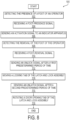
- a method 100 of operating a medical device treatment machine 10 includes, at step 102, detecting, by a sensing apparatus, such as for example a proximity sensor or a pedal or lever disposed on the medical device treatment machine, the presence of a foot of an operator in a sensing zone of the sensing apparatus.
- the method 100 then includes, at step 104, receiving, by a controller of the medical device treatment machine, a foot-presence signal from the sensing apparatus.
- the method 100 includes sending, by the controller, an activation signal to an indicator apparatus of the medical device treatment machine to activate the indicator apparatus.
- the indicator apparatus may be a light indicator and the activation signal may be an illumination signal to illuminate the light indicator.
- the activation signal may be an illumination color-change signal to change an illumination color of the light indicator.
- Other embodiments are also contemplated, as previously described.
- the method 100 further includes detecting, by the sensing apparatus, a removal of the foot of the operator from the sensing zone of the sensing apparatus.
- the method 100 then includes at step 110, receiving, by the controller, a foot-removal signal from the sensing apparatus.
- the method 100 includes sending, at step 116, by the controller, an unlatch signal after a predetermined period of time upon receipt of the foot-removal signal.
- the controller sends the unlatch signal to an actuator, for example the afore described second actuator 58 of the latch and lock assembly.
- the method 100 then includes, at step 118, rotating, by the actuator, a door opening tab of the latch and lock assembly that is in abutting contact with a lever to pivot the lever from a latched position to an unlatched position.
- the method 100 may additionally include automatically moving a door of the medical device treatment machine from a closed position to an open position via a biasing force of a hinge of the door by a hinge biasing member.
- the method 100 may include sending, at step 112, by the controller, an unlock signal after a first predetermined period of time from receipt of the foot removal signal.
- the controller sends the unlock signal to a first actuator of the latch and lock assembly of the medical device treatment machine.
- the method 100 may then include moving, by the first actuator, a locking tab of the latch and lock assembly from a locked position to an unlocked position.
- the sending, at step 116, by the controller of the unlatch signal may occur, therefore, at a second predetermined period of time after receipt of the foot-removal signal and after the first predetermined period of time at which the unlock signal is sent.
- a non-transitory computer-readable medium storing program code.
- the non-transitory computer-readable medium is configured to perform the steps of the method previously described.
Landscapes
- Health & Medical Sciences (AREA)
- Electromagnetism (AREA)
- Physics & Mathematics (AREA)
- Life Sciences & Earth Sciences (AREA)
- Veterinary Medicine (AREA)
- Public Health (AREA)
- General Health & Medical Sciences (AREA)
- Animal Behavior & Ethology (AREA)
- Engineering & Computer Science (AREA)
- Epidemiology (AREA)
- Surgery (AREA)
- Molecular Biology (AREA)
- Biomedical Technology (AREA)
- Oral & Maxillofacial Surgery (AREA)
- Medical Informatics (AREA)
- Heart & Thoracic Surgery (AREA)
- Pathology (AREA)
- Nuclear Medicine, Radiotherapy & Molecular Imaging (AREA)
- Mechanical Engineering (AREA)
- Apparatus For Disinfection Or Sterilisation (AREA)
- Chemical & Material Sciences (AREA)
- Medicinal Chemistry (AREA)
- External Artificial Organs (AREA)
- Surgical Instruments (AREA)
Claims (15)
- Machine de traitement de dispositif médical (10) comprenant :une chambre de traitement (12) pour laver, désinfecter et/ou stériliser un dispositif médical,une porte (14) attachée de manière articulée à la chambre de traitement (12) et mobile entre une position ouverte, pour exposer la chambre de traitement (12), et une position fermée, pour sceller la chambre de traitement (12), dans laquelle la porte (14) comprend une goupille de loquet (16) sur un premier côté (20) de la porte (14), etun ensemble loquet et verrou (30) fixé à une paroi de la chambre de traitement (12), dans laquelle l'ensemble loquet et verrou (30) comprend :un levier (44) pivotant entre une position enclenchée et une position non enclenchée, dans laquelle, dans la position enclenchée, le levier (44) vient en prise avec la goupille de loquet (16) pour empêcher un mouvement de la porte (14) de la position fermée à la position ouverte, et dans laquelle, dans la position non enclenchée, le levier (44) se détache de la goupille de loquet (16) pour permettre un mouvement de la porte (14) de la position fermée à la position ouverte,un premier actionneur (56) et une languette de verrouillage (60), dans laquelle le premier actionneur (56) est couplé à la languette de verrouillage (60) pour déplacer sélectivement la languette de verrouillage (60) entre une position verrouillée et une position déverrouillée, dans laquelle, dans la position verrouillée, la languette de verrouillage (60) est configurée pour bloquer un mouvement pivotant du levier (44) de la position enclenchée à la position non enclenchée, et dans laquelle, dans la position déverrouillée, la languette de verrouillage (60) est configurée pour permettre un mouvement pivotant du levier (44) de la position enclenchée à la position non enclenchée, etun second actionneur (58) et une languette d'ouverture de porte (64), dans laquelle la languette d'ouverture de porte (64) comporte un segment de came, et dans laquelle le second actionneur (58) est couplé à la languette d'ouverture de porte (64) pour faire tourner sélectivement la languette d'ouverture de porte (64) entre une première position et une seconde position lorsque la languette de verrouillage (60) est dans la position déverrouillée, dans laquelle lorsque la languette d'ouverture de porte (64) est dans la première position, le levier (44) est dans une position enclenchée, et dans laquelle lorsque la languette d'ouverture de porte (64) est tournée de la première position à la seconde position, le segment de came (64c) de la languette d'ouverture de porte (64) vient en butée contre un côté du levier (44) pour pousser le levier (44) de la position enclenchée à la position non enclenchée.
- Machine de traitement de dispositif médical (10) selon la revendication 1, dans laquelle la languette de verrouillage (60) fonctionne sur un premier côté (62) du levier (44) et la languette d'ouverture de porte (64) fonctionne sur un second côté (66) du levier (44), opposé au premier côté (62) du levier (44), ou dans laquelle, dans la position verrouillée, la languette de verrouillage (60) vient de préférence en butée contre une partie du levier (44), et dans laquelle, dans la position déverrouillée, la languette de verrouillage (60) est de préférence espacée du levier (44).
- Machine de traitement de dispositif médical (10) selon l'une quelconque des revendications 1 et 2, comprenant également un élément de sollicitation de levier (54) configuré pour solliciter le levier vers la position enclenchée, ou dans laquelle l'élément de sollicitation de levier (54) est de préférence un ressort, ou dans laquelle le premier actionneur (56) et le second actionneur (58) sont de préférence des solénoïdes de type à traction, ou comprenant de préférence également un boîtier fixe sur lequel au moins l'un du levier (44), du premier actionneur (56), de la languette de verrouillage (60), du second actionneur (58), de la languette d'ouverture de porte (64) et de l'élément de sollicitation de levier (54) est monté.
- Machine de traitement de dispositif médical (10) selon la revendication 3, comprenant également un boîtier réglable auquel le boîtier fixe est attaché de manière réglable.
- Machine de traitement de dispositif médical (10) selon la revendication 4, comprenant également une tige d'alignement (36) traversant une paroi du boîtier fixe et une paroi du boîtier réglable pour aligner le boîtier fixe par rapport au boîtier réglable.
- Machine de traitement de dispositif médical (10) selon l'une quelconque des revendications 4 à 5, comprenant également un accordeur de réglage (38) traversant une paroi du boîtier fixe et une paroi du boîtier réglable, l'accordeur de réglage (38) comprenant un boulon fileté (40) et un contre-écrou (42) associé, qui, lorsqu'ils sont serrés, empêchent un mouvement du boîtier fixe par rapport au boîtier de réglage.
- Machine de traitement de dispositif médical (10) selon l'une quelconque des revendications 3 à 6, comprenant également un bloc de réglage de languette d'ouverture de porte (68) monté sur le boîtier fixe et comportant une vis (68a), dans laquelle le bloc de réglage de languette d'ouverture de porte (68) est configuré pour régler la position de la languette d'ouverture de porte (64) à l'intérieur du boîtier fixe par rapport au levier (44) .
- Machine de traitement de dispositif médical (10) selon l'une quelconque des revendications 1 à 7, comprenant également un commutateur (70) configuré pour détecter si et quand la languette de verrouillage (60) est dans une position verrouillée ou une position déverrouillée.
- Machine de traitement de dispositif médical (10) selon l'une quelconque des revendications 1 à 8, comprenant également une charnière (18) sur un second côté (22) de la porte (14) opposé au premier côté (20) de la porte (14), dans laquelle la charnière (18) de la porte (14) comprend de préférence un élément de sollicitation de charnière (18a) pour solliciter la porte (14) vers une position ouverte pour déplacer automatiquement la porte (14) de la position fermée à la position ouverte lorsque le levier (44) est dans la position non enclenchée.
- Machine de traitement de dispositif médical (10) selon l'une quelconque des revendications 1 à 9, comprenant également :une goupille d'arrêt (82) se prolongeant depuis la chambre (12), etun bloc d'arrêt (86) fixé à la porte (14), le bloc d'arrêt (86) comprenant une goupille galet (84) se prolongeant depuis le bloc d'arrêt (86) dans une direction configurée pour être perpendiculaire à la goupille d'arrêt (82) lorsque la porte (14) est dans une position fermée,dans laquelle lorsque la porte (14) est dans une position fermée, la goupille galet (84) vient en butée coulissante contre la goupille d'arrêt (82) pour permettre un mouvement latéral de la porte (14) entre la position fermée et la position ouverte et bloquer un mouvement vertical de la porte (14) dans une direction perpendiculaire au mouvement latéral de la porte (14).
- Machine de traitement de dispositif médical (10) selon l'une quelconque des revendications 1 à 10, comprenant également :un appareil de détection (94) pour détecter la présence et le retrait d'un pied d'un opérateur dans une zone de détection (96) de l'appareil de détection (94), etun dispositif de commande (92) pour commander les opérations du second actionneur (58) en fonction de la détection de la présence et du retrait du pied de l'opérateur dans la zone de détection (96) de l'appareil de détection (94).
- Machine de traitement de dispositif médical (10) selon la revendication 11, dans laquelle le dispositif de commande (92) est configuré pour :recevoir un signal de présence de pied provenant de l'appareil de détection (94) lorsque l'appareil de détection (94) détecte la présence du pied de l'opérateur dans la zone de détection (96) de l'appareil de détection (94),envoyer un signal d'activation à un appareil indicateur (98) sur la machine de traitement de dispositif médical (10) pour activer l'appareil indicateur (98),recevoir un signal de retrait de pied provenant de l'appareil de détection (94) lorsque le capteur de pied détecte le retrait du pied de l'opérateur de la zone de détection (96) de l'appareil de détection (94), etenvoyer un signal de désenclenchement au second actionneur (58) pour faire tourner la languette d'ouverture de porte (60) en contact de butée avec le levier (44) afin de faire pivoter le levier (44) de la position enclenchée à la position non enclenchée.
- Procédé de fonctionnement d'une machine de traitement de dispositif médical (10) selon l'une quelconque des revendications 1 à 12,
le procédé comprenant les étapes de :
rotation, par le second actionneur (58), de la languette d'ouverture de porte (60) de l'ensemble loquet et verrou (30) qui est en contact de butée avec le levier (44) pour faire pivoter le levier (44) de la position enclenchée à la position non enclenchée. - Procédé selon la revendication 13, comprenant également les étapes de :détection, par un appareil de détection (94) disposé sur la machine de traitement de dispositif médical (10), de la présence d'un pied d'un opérateur dans une zone de détection (96) de l'appareil de détection (94),réception, par un dispositif de commande (92) de la machine de traitement de dispositif médical (10), d'un signal de présence de pied provenant de l'appareil de détection (94),envoi, par le dispositif de commande (92), d'un signal d'activation à un appareil indicateur (98) sur la machine de traitement de dispositif médical (10) pour activer l'appareil indicateur (98),détection, par l'appareil de détection (94), du retrait du pied de l'opérateur de la zone de détection (96) de l'appareil de détection (94), et,réception, par le dispositif de commande (92), d'un signal de retrait de pied provenant de l'appareil de détection (94),envoi, par le dispositif de commande (92), d'un signal de désenclenchement au premier actionneur (56) de l'ensemble loquet et verrou (30) de la machine de traitement de dispositif médical (10) .
- Procédé selon la revendication 14, dans lequel le signal de désenclenchement est envoyé à l'actionneur une période de temps prédéterminée après la réception du signal de retrait de pied, ou comprenant de préférence également :
le déplacement automatique de la porte (14) de la machine de traitement de dispositif médical (10) de la position fermée à la position ouverte par l'intermédiaire d'une force de sollicitation sur une charnière (18) de la porte (14) par un élément de sollicitation de charnière (18a).
Priority Applications (1)
| Application Number | Priority Date | Filing Date | Title |
|---|---|---|---|
| EP24200342.4A EP4455430B1 (fr) | 2019-09-12 | 2020-08-31 | Loquet de porte, verrou et mécanisme d'ouverture pour système de traitement de dispositif medical |
Applications Claiming Priority (2)
| Application Number | Priority Date | Filing Date | Title |
|---|---|---|---|
| US201962899192P | 2019-09-12 | 2019-09-12 | |
| PCT/US2020/048705 WO2021050309A2 (fr) | 2019-09-12 | 2020-08-31 | Loquet de porte, verrou et mécanisme d'ouverture pour système de traitement de dispositif médical |
Related Child Applications (2)
| Application Number | Title | Priority Date | Filing Date |
|---|---|---|---|
| EP24200342.4A Division-Into EP4455430B1 (fr) | 2019-09-12 | 2020-08-31 | Loquet de porte, verrou et mécanisme d'ouverture pour système de traitement de dispositif medical |
| EP24200342.4A Division EP4455430B1 (fr) | 2019-09-12 | 2020-08-31 | Loquet de porte, verrou et mécanisme d'ouverture pour système de traitement de dispositif medical |
Publications (2)
| Publication Number | Publication Date |
|---|---|
| EP4028617A2 EP4028617A2 (fr) | 2022-07-20 |
| EP4028617B1 true EP4028617B1 (fr) | 2024-10-30 |
Family
ID=72470613
Family Applications (2)
| Application Number | Title | Priority Date | Filing Date |
|---|---|---|---|
| EP20771409.8A Active EP4028617B1 (fr) | 2019-09-12 | 2020-08-31 | Loquet de porte, verrou et mécanisme d'ouverture pour système de traitement de dispositif médical |
| EP24200342.4A Active EP4455430B1 (fr) | 2019-09-12 | 2020-08-31 | Loquet de porte, verrou et mécanisme d'ouverture pour système de traitement de dispositif medical |
Family Applications After (1)
| Application Number | Title | Priority Date | Filing Date |
|---|---|---|---|
| EP24200342.4A Active EP4455430B1 (fr) | 2019-09-12 | 2020-08-31 | Loquet de porte, verrou et mécanisme d'ouverture pour système de traitement de dispositif medical |
Country Status (7)
| Country | Link |
|---|---|
| US (2) | US11980697B2 (fr) |
| EP (2) | EP4028617B1 (fr) |
| AU (1) | AU2020347095B2 (fr) |
| CA (1) | CA3150989A1 (fr) |
| ES (1) | ES3000682T3 (fr) |
| MX (1) | MX2022002945A (fr) |
| WO (1) | WO2021050309A2 (fr) |
Families Citing this family (3)
| Publication number | Priority date | Publication date | Assignee | Title |
|---|---|---|---|---|
| EP3611316A1 (fr) * | 2018-08-13 | 2020-02-19 | Montajes Electronicos Dorcas, S.L. | Dispositif de verrouillage |
| CN115711075B (zh) * | 2022-10-26 | 2025-07-08 | 张家港市环宇制药设备有限公司 | 灭菌柜自动开关门装置 |
| WO2025025105A1 (fr) * | 2023-07-31 | 2025-02-06 | 深圳市理邦精密仪器股份有限公司 | Dispositif de test médical |
Citations (1)
| Publication number | Priority date | Publication date | Assignee | Title |
|---|---|---|---|---|
| EP1405967A1 (fr) * | 2002-10-01 | 2004-04-07 | M.O.COM. S.r.L. | Dispositif de verrouillage notamment pour un appareil pour stériliser à vapeur |
Family Cites Families (22)
| Publication number | Priority date | Publication date | Assignee | Title |
|---|---|---|---|---|
| US971423A (en) * | 1910-05-06 | 1910-09-27 | Frank Walters | Lock. |
| US3751088A (en) * | 1971-05-24 | 1973-08-07 | Schlage Lock Co | Electromagnetic lock |
| US3767242A (en) | 1971-10-29 | 1973-10-23 | Lectron Products | Solenoid operated door lock |
| US3874117A (en) | 1973-09-28 | 1975-04-01 | R H Boehm Company Inc | Electric door opener |
| EP0035979B1 (fr) * | 1980-03-11 | 1984-07-11 | Soc. F.A.M.A. di Sandra Borgato & CO.S.n.c. | Serrure à gâche automatique actionnée manuellement et électriquement |
| NO176933C (no) | 1989-01-24 | 1995-06-21 | Siegenia Frank Kg | Vindu eller dör med ei vippbar og svingbar vindusramme eller dörblad |
| US5223229A (en) | 1990-07-19 | 1993-06-29 | Midmark Corporation | Sterilizing apparatus having automatically actuated door |
| GB9120512D0 (en) | 1991-09-26 | 1991-11-06 | Newtronics Sa | Locks |
| US5263596A (en) | 1991-12-02 | 1993-11-23 | Williams David R | Medication dispenser station sub-assembly |
| US5460294A (en) | 1994-05-12 | 1995-10-24 | Pyxis Corporation | Single dose pharmaceutical dispenser subassembly |
| US5879036A (en) | 1996-09-19 | 1999-03-09 | Moline; Steven S. | Door interlock for an appliance such as a washer |
| US20030222548A1 (en) | 2002-05-31 | 2003-12-04 | Richardson William R. | Storage device for health care facility |
| US6967587B2 (en) | 2003-09-22 | 2005-11-22 | Sanidoor, Llc | Hands-free door opener and method |
| US7038409B1 (en) | 2005-03-16 | 2006-05-02 | Wayne-Dalton Corp. | Operating system utilizing a delay-open function for a motorized barrier operator |
| JP5467911B2 (ja) * | 2010-03-29 | 2014-04-09 | 富士フイルム株式会社 | 洗浄消毒装置及び洗浄消毒装置の制御方法 |
| GB2495290A (en) | 2011-10-04 | 2013-04-10 | Nissan Motor Mfg Uk Ltd | Apparatus and method for opening a closure of a vehicle |
| WO2013126673A1 (fr) | 2012-02-23 | 2013-08-29 | Master Lock Company Llc | Ensembles et agencements de verrouillage de porte |
| US20140265805A1 (en) | 2013-03-15 | 2014-09-18 | Whirlpool Corporation | Appliance with automatic door opener |
| DE102013015119A1 (de) | 2013-09-12 | 2015-03-12 | Brose Fahrzeugteile Gmbh & Co. Kommanditgesellschaft, Hallstadt | Stellvorrichtung zur Verstellung eines zwischen einer Schließstellung und einer Offenstellung verstellbaren Fahrzeugteils |
| US9474432B2 (en) | 2013-12-11 | 2016-10-25 | Whirlpool Corporation | Household appliance and method of opening the same |
| CN106121384B (zh) * | 2016-08-22 | 2018-05-25 | 安徽信息工程学院 | 平开电动自动门的防意外机械卡锁装置及其开关门方法 |
| CN208710104U (zh) * | 2017-12-28 | 2019-04-09 | 广州吉好医疗科技有限公司 | 带有内镜接头脱落感应装置的多槽内镜清洗消毒机 |
-
2020
- 2020-08-31 EP EP20771409.8A patent/EP4028617B1/fr active Active
- 2020-08-31 WO PCT/US2020/048705 patent/WO2021050309A2/fr not_active Ceased
- 2020-08-31 MX MX2022002945A patent/MX2022002945A/es unknown
- 2020-08-31 AU AU2020347095A patent/AU2020347095B2/en active Active
- 2020-08-31 US US17/007,289 patent/US11980697B2/en active Active
- 2020-08-31 EP EP24200342.4A patent/EP4455430B1/fr active Active
- 2020-08-31 CA CA3150989A patent/CA3150989A1/fr active Pending
- 2020-08-31 ES ES20771409T patent/ES3000682T3/es active Active
-
2024
- 2024-04-10 US US18/631,411 patent/US20240252706A1/en active Pending
Patent Citations (1)
| Publication number | Priority date | Publication date | Assignee | Title |
|---|---|---|---|---|
| EP1405967A1 (fr) * | 2002-10-01 | 2004-04-07 | M.O.COM. S.r.L. | Dispositif de verrouillage notamment pour un appareil pour stériliser à vapeur |
Also Published As
| Publication number | Publication date |
|---|---|
| AU2020347095A1 (en) | 2022-03-31 |
| ES3000682T3 (en) | 2025-03-03 |
| CA3150989A1 (fr) | 2021-03-18 |
| WO2021050309A3 (fr) | 2021-04-15 |
| WO2021050309A2 (fr) | 2021-03-18 |
| US20240252706A1 (en) | 2024-08-01 |
| EP4455430A3 (fr) | 2025-01-29 |
| AU2020347095B2 (en) | 2023-11-23 |
| EP4028617A2 (fr) | 2022-07-20 |
| EP4455430B1 (fr) | 2025-11-12 |
| MX2022002945A (es) | 2022-06-14 |
| US11980697B2 (en) | 2024-05-14 |
| US20210079711A1 (en) | 2021-03-18 |
| EP4455430A2 (fr) | 2024-10-30 |
Similar Documents
| Publication | Publication Date | Title |
|---|---|---|
| US20240252706A1 (en) | Door latch, lock and open mechanism for medical device treatment system | |
| US8814233B2 (en) | Safety switch for generating a system enable signal depending on the position of a movable guard door | |
| JP6309965B2 (ja) | 防護扉監視システム | |
| US9663981B2 (en) | Vehicle closure member power actuator control | |
| US8844984B2 (en) | Door lock device | |
| US10988959B1 (en) | Rim strike assembly and methods of use | |
| KR101396927B1 (ko) | 세탁기용 도어락 장치 | |
| US9567782B2 (en) | Lower lock of the passive door blade of a double door | |
| JP4832379B2 (ja) | 高圧蒸気滅菌器 | |
| AU2003281069A1 (en) | Door locking mechanism | |
| US6391258B1 (en) | Pressure vessel having electromechanical latching mechanism | |
| EP3108080A1 (fr) | Loquet de canal actionné par un outil | |
| KR102691524B1 (ko) | 푸시-푸시 도어 래치 및 이를 구비한 가전기기 | |
| CA2401162C (fr) | Fermetures pour portes coupe-feu | |
| US11759538B2 (en) | Door locking mechanism for a sterilizer | |
| EA017821B1 (ru) | Замок для усиленных дверей и тому подобного | |
| EP1669530B1 (fr) | Dispositif de verrouillage pour portes de machines industrielles | |
| EP3372767B1 (fr) | Dispositif de sécurité pour fermer des portes d'inspection | |
| EP0652343A1 (fr) | Ensemble de verrouillage actionnable par poignée antipanique | |
| CN119640542A (zh) | 一种洗涤设备自动开关门控制方法 | |
| JP2012172327A (ja) | 窓用錠装置 |
Legal Events
| Date | Code | Title | Description |
|---|---|---|---|
| STAA | Information on the status of an ep patent application or granted ep patent |
Free format text: STATUS: UNKNOWN |
|
| STAA | Information on the status of an ep patent application or granted ep patent |
Free format text: STATUS: THE INTERNATIONAL PUBLICATION HAS BEEN MADE |
|
| PUAI | Public reference made under article 153(3) epc to a published international application that has entered the european phase |
Free format text: ORIGINAL CODE: 0009012 |
|
| STAA | Information on the status of an ep patent application or granted ep patent |
Free format text: STATUS: REQUEST FOR EXAMINATION WAS MADE |
|
| 17P | Request for examination filed |
Effective date: 20220317 |
|
| AK | Designated contracting states |
Kind code of ref document: A2 Designated state(s): AL AT BE BG CH CY CZ DE DK EE ES FI FR GB GR HR HU IE IS IT LI LT LU LV MC MK MT NL NO PL PT RO RS SE SI SK SM TR |
|
| DAV | Request for validation of the european patent (deleted) | ||
| DAX | Request for extension of the european patent (deleted) | ||
| STAA | Information on the status of an ep patent application or granted ep patent |
Free format text: STATUS: EXAMINATION IS IN PROGRESS |
|
| 17Q | First examination report despatched |
Effective date: 20230414 |
|
| P01 | Opt-out of the competence of the unified patent court (upc) registered |
Effective date: 20230513 |
|
| GRAP | Despatch of communication of intention to grant a patent |
Free format text: ORIGINAL CODE: EPIDOSNIGR1 |
|
| STAA | Information on the status of an ep patent application or granted ep patent |
Free format text: STATUS: GRANT OF PATENT IS INTENDED |
|
| INTG | Intention to grant announced |
Effective date: 20240716 |
|
| GRAS | Grant fee paid |
Free format text: ORIGINAL CODE: EPIDOSNIGR3 |
|
| GRAA | (expected) grant |
Free format text: ORIGINAL CODE: 0009210 |
|
| STAA | Information on the status of an ep patent application or granted ep patent |
Free format text: STATUS: THE PATENT HAS BEEN GRANTED |
|
| AK | Designated contracting states |
Kind code of ref document: B1 Designated state(s): AL AT BE BG CH CY CZ DE DK EE ES FI FR GB GR HR HU IE IS IT LI LT LU LV MC MK MT NL NO PL PT RO RS SE SI SK SM TR |
|
| REG | Reference to a national code |
Ref country code: GB Ref legal event code: FG4D |
|
| REG | Reference to a national code |
Ref country code: CH Ref legal event code: EP |
|
| REG | Reference to a national code |
Ref country code: DE Ref legal event code: R096 Ref document number: 602020040358 Country of ref document: DE |
|
| REG | Reference to a national code |
Ref country code: IE Ref legal event code: FG4D |
|
| REG | Reference to a national code |
Ref country code: LT Ref legal event code: MG9D |
|
| REG | Reference to a national code |
Ref country code: ES Ref legal event code: FG2A Ref document number: 3000682 Country of ref document: ES Kind code of ref document: T3 Effective date: 20250303 |
|
| REG | Reference to a national code |
Ref country code: NL Ref legal event code: MP Effective date: 20241030 |
|
| PG25 | Lapsed in a contracting state [announced via postgrant information from national office to epo] |
Ref country code: PT Free format text: LAPSE BECAUSE OF FAILURE TO SUBMIT A TRANSLATION OF THE DESCRIPTION OR TO PAY THE FEE WITHIN THE PRESCRIBED TIME-LIMIT Effective date: 20250228 Ref country code: HR Free format text: LAPSE BECAUSE OF FAILURE TO SUBMIT A TRANSLATION OF THE DESCRIPTION OR TO PAY THE FEE WITHIN THE PRESCRIBED TIME-LIMIT Effective date: 20241030 Ref country code: IS Free format text: LAPSE BECAUSE OF FAILURE TO SUBMIT A TRANSLATION OF THE DESCRIPTION OR TO PAY THE FEE WITHIN THE PRESCRIBED TIME-LIMIT Effective date: 20250228 |
|
| PG25 | Lapsed in a contracting state [announced via postgrant information from national office to epo] |
Ref country code: FI Free format text: LAPSE BECAUSE OF FAILURE TO SUBMIT A TRANSLATION OF THE DESCRIPTION OR TO PAY THE FEE WITHIN THE PRESCRIBED TIME-LIMIT Effective date: 20241030 Ref country code: NL Free format text: LAPSE BECAUSE OF FAILURE TO SUBMIT A TRANSLATION OF THE DESCRIPTION OR TO PAY THE FEE WITHIN THE PRESCRIBED TIME-LIMIT Effective date: 20241030 |
|
| REG | Reference to a national code |
Ref country code: AT Ref legal event code: MK05 Ref document number: 1737018 Country of ref document: AT Kind code of ref document: T Effective date: 20241030 |
|
| PG25 | Lapsed in a contracting state [announced via postgrant information from national office to epo] |
Ref country code: BG Free format text: LAPSE BECAUSE OF FAILURE TO SUBMIT A TRANSLATION OF THE DESCRIPTION OR TO PAY THE FEE WITHIN THE PRESCRIBED TIME-LIMIT Effective date: 20241030 |
|
| PG25 | Lapsed in a contracting state [announced via postgrant information from national office to epo] |
Ref country code: NO Free format text: LAPSE BECAUSE OF FAILURE TO SUBMIT A TRANSLATION OF THE DESCRIPTION OR TO PAY THE FEE WITHIN THE PRESCRIBED TIME-LIMIT Effective date: 20250130 |
|
| PG25 | Lapsed in a contracting state [announced via postgrant information from national office to epo] |
Ref country code: LV Free format text: LAPSE BECAUSE OF FAILURE TO SUBMIT A TRANSLATION OF THE DESCRIPTION OR TO PAY THE FEE WITHIN THE PRESCRIBED TIME-LIMIT Effective date: 20241030 Ref country code: GR Free format text: LAPSE BECAUSE OF FAILURE TO SUBMIT A TRANSLATION OF THE DESCRIPTION OR TO PAY THE FEE WITHIN THE PRESCRIBED TIME-LIMIT Effective date: 20250131 Ref country code: AT Free format text: LAPSE BECAUSE OF FAILURE TO SUBMIT A TRANSLATION OF THE DESCRIPTION OR TO PAY THE FEE WITHIN THE PRESCRIBED TIME-LIMIT Effective date: 20241030 |
|
| PG25 | Lapsed in a contracting state [announced via postgrant information from national office to epo] |
Ref country code: PL Free format text: LAPSE BECAUSE OF FAILURE TO SUBMIT A TRANSLATION OF THE DESCRIPTION OR TO PAY THE FEE WITHIN THE PRESCRIBED TIME-LIMIT Effective date: 20241030 |
|
| PG25 | Lapsed in a contracting state [announced via postgrant information from national office to epo] |
Ref country code: RS Free format text: LAPSE BECAUSE OF FAILURE TO SUBMIT A TRANSLATION OF THE DESCRIPTION OR TO PAY THE FEE WITHIN THE PRESCRIBED TIME-LIMIT Effective date: 20250130 |
|
| PG25 | Lapsed in a contracting state [announced via postgrant information from national office to epo] |
Ref country code: SM Free format text: LAPSE BECAUSE OF FAILURE TO SUBMIT A TRANSLATION OF THE DESCRIPTION OR TO PAY THE FEE WITHIN THE PRESCRIBED TIME-LIMIT Effective date: 20241030 |
|
| PG25 | Lapsed in a contracting state [announced via postgrant information from national office to epo] |
Ref country code: DK Free format text: LAPSE BECAUSE OF FAILURE TO SUBMIT A TRANSLATION OF THE DESCRIPTION OR TO PAY THE FEE WITHIN THE PRESCRIBED TIME-LIMIT Effective date: 20241030 |
|
| PG25 | Lapsed in a contracting state [announced via postgrant information from national office to epo] |
Ref country code: EE Free format text: LAPSE BECAUSE OF FAILURE TO SUBMIT A TRANSLATION OF THE DESCRIPTION OR TO PAY THE FEE WITHIN THE PRESCRIBED TIME-LIMIT Effective date: 20241030 |
|
| PG25 | Lapsed in a contracting state [announced via postgrant information from national office to epo] |
Ref country code: RO Free format text: LAPSE BECAUSE OF FAILURE TO SUBMIT A TRANSLATION OF THE DESCRIPTION OR TO PAY THE FEE WITHIN THE PRESCRIBED TIME-LIMIT Effective date: 20241030 |
|
| PG25 | Lapsed in a contracting state [announced via postgrant information from national office to epo] |
Ref country code: SK Free format text: LAPSE BECAUSE OF FAILURE TO SUBMIT A TRANSLATION OF THE DESCRIPTION OR TO PAY THE FEE WITHIN THE PRESCRIBED TIME-LIMIT Effective date: 20241030 |
|
| PG25 | Lapsed in a contracting state [announced via postgrant information from national office to epo] |
Ref country code: CZ Free format text: LAPSE BECAUSE OF FAILURE TO SUBMIT A TRANSLATION OF THE DESCRIPTION OR TO PAY THE FEE WITHIN THE PRESCRIBED TIME-LIMIT Effective date: 20241030 |
|
| REG | Reference to a national code |
Ref country code: DE Ref legal event code: R097 Ref document number: 602020040358 Country of ref document: DE |
|
| PLBE | No opposition filed within time limit |
Free format text: ORIGINAL CODE: 0009261 |
|
| STAA | Information on the status of an ep patent application or granted ep patent |
Free format text: STATUS: NO OPPOSITION FILED WITHIN TIME LIMIT |
|
| PG25 | Lapsed in a contracting state [announced via postgrant information from national office to epo] |
Ref country code: SE Free format text: LAPSE BECAUSE OF FAILURE TO SUBMIT A TRANSLATION OF THE DESCRIPTION OR TO PAY THE FEE WITHIN THE PRESCRIBED TIME-LIMIT Effective date: 20241030 |
|
| 26N | No opposition filed |
Effective date: 20250731 |
|
| PGFP | Annual fee paid to national office [announced via postgrant information from national office to epo] |
Ref country code: ES Payment date: 20250901 Year of fee payment: 6 |
|
| PGFP | Annual fee paid to national office [announced via postgrant information from national office to epo] |
Ref country code: DE Payment date: 20250827 Year of fee payment: 6 |
|
| PGFP | Annual fee paid to national office [announced via postgrant information from national office to epo] |
Ref country code: IT Payment date: 20250820 Year of fee payment: 6 |
|
| PGFP | Annual fee paid to national office [announced via postgrant information from national office to epo] |
Ref country code: GB Payment date: 20250827 Year of fee payment: 6 |
|
| PGFP | Annual fee paid to national office [announced via postgrant information from national office to epo] |
Ref country code: FR Payment date: 20250825 Year of fee payment: 6 |
|
| REG | Reference to a national code |
Ref country code: CH Ref legal event code: H13 Free format text: ST27 STATUS EVENT CODE: U-0-0-H10-H13 (AS PROVIDED BY THE NATIONAL OFFICE) Effective date: 20260324 |
|
| PG25 | Lapsed in a contracting state [announced via postgrant information from national office to epo] |
Ref country code: MC Free format text: LAPSE BECAUSE OF FAILURE TO SUBMIT A TRANSLATION OF THE DESCRIPTION OR TO PAY THE FEE WITHIN THE PRESCRIBED TIME-LIMIT Effective date: 20241030 |
|
| PG25 | Lapsed in a contracting state [announced via postgrant information from national office to epo] |
Ref country code: LU Free format text: LAPSE BECAUSE OF NON-PAYMENT OF DUE FEES Effective date: 20250831 |