EP4028654B1 - Module de refroidissement pour véhicule automobile à turbomachine tangentielle - Google Patents
Module de refroidissement pour véhicule automobile à turbomachine tangentielle Download PDFInfo
- Publication number
- EP4028654B1 EP4028654B1 EP20780769.4A EP20780769A EP4028654B1 EP 4028654 B1 EP4028654 B1 EP 4028654B1 EP 20780769 A EP20780769 A EP 20780769A EP 4028654 B1 EP4028654 B1 EP 4028654B1
- Authority
- EP
- European Patent Office
- Prior art keywords
- shutters
- ventilation device
- shutter
- frame
- cooling module
- Prior art date
- Legal status (The legal status is an assumption and is not a legal conclusion. Google has not performed a legal analysis and makes no representation as to the accuracy of the status listed.)
- Active
Links
Images




Classifications
-
- B—PERFORMING OPERATIONS; TRANSPORTING
- B60—VEHICLES IN GENERAL
- B60K—ARRANGEMENT OR MOUNTING OF PROPULSION UNITS OR OF TRANSMISSIONS IN VEHICLES; ARRANGEMENT OR MOUNTING OF PLURAL DIVERSE PRIME-MOVERS IN VEHICLES; AUXILIARY DRIVES FOR VEHICLES; INSTRUMENTATION OR DASHBOARDS FOR VEHICLES; ARRANGEMENTS IN CONNECTION WITH COOLING, AIR INTAKE, GAS EXHAUST OR FUEL SUPPLY OF PROPULSION UNITS IN VEHICLES
- B60K11/00—Arrangement in connection with cooling of propulsion units
- B60K11/08—Air inlets for cooling; Shutters or blinds therefor
- B60K11/085—Air inlets for cooling; Shutters or blinds therefor with adjustable shutters or blinds
-
- B—PERFORMING OPERATIONS; TRANSPORTING
- B60—VEHICLES IN GENERAL
- B60K—ARRANGEMENT OR MOUNTING OF PROPULSION UNITS OR OF TRANSMISSIONS IN VEHICLES; ARRANGEMENT OR MOUNTING OF PLURAL DIVERSE PRIME-MOVERS IN VEHICLES; AUXILIARY DRIVES FOR VEHICLES; INSTRUMENTATION OR DASHBOARDS FOR VEHICLES; ARRANGEMENTS IN CONNECTION WITH COOLING, AIR INTAKE, GAS EXHAUST OR FUEL SUPPLY OF PROPULSION UNITS IN VEHICLES
- B60K11/00—Arrangement in connection with cooling of propulsion units
- B60K11/06—Arrangement in connection with cooling of propulsion units with air cooling
-
- F—MECHANICAL ENGINEERING; LIGHTING; HEATING; WEAPONS; BLASTING
- F01—MACHINES OR ENGINES IN GENERAL; ENGINE PLANTS IN GENERAL; STEAM ENGINES
- F01P—COOLING OF MACHINES OR ENGINES IN GENERAL; COOLING OF INTERNAL-COMBUSTION ENGINES
- F01P11/00—Component parts, details, or accessories not provided for in, or of interest apart from, groups F01P1/00 - F01P9/00
- F01P11/10—Guiding or ducting cooling-air, to, or from, liquid-to-air heat exchangers
-
- F—MECHANICAL ENGINEERING; LIGHTING; HEATING; WEAPONS; BLASTING
- F01—MACHINES OR ENGINES IN GENERAL; ENGINE PLANTS IN GENERAL; STEAM ENGINES
- F01P—COOLING OF MACHINES OR ENGINES IN GENERAL; COOLING OF INTERNAL-COMBUSTION ENGINES
- F01P5/00—Pumping cooling-air or liquid coolants
- F01P5/02—Pumping cooling-air; Arrangements of cooling-air pumps, e.g. fans or blowers
- F01P5/06—Guiding or ducting air to, or from, ducted fans
-
- F—MECHANICAL ENGINEERING; LIGHTING; HEATING; WEAPONS; BLASTING
- F01—MACHINES OR ENGINES IN GENERAL; ENGINE PLANTS IN GENERAL; STEAM ENGINES
- F01P—COOLING OF MACHINES OR ENGINES IN GENERAL; COOLING OF INTERNAL-COMBUSTION ENGINES
- F01P7/00—Controlling of coolant flow
- F01P7/02—Controlling of coolant flow the coolant being cooling-air
- F01P7/10—Controlling of coolant flow the coolant being cooling-air by throttling amount of air flowing through liquid-to-air heat exchangers
-
- F—MECHANICAL ENGINEERING; LIGHTING; HEATING; WEAPONS; BLASTING
- F04—POSITIVE - DISPLACEMENT MACHINES FOR LIQUIDS; PUMPS FOR LIQUIDS OR ELASTIC FLUIDS
- F04D—NON-POSITIVE-DISPLACEMENT PUMPS
- F04D17/00—Radial-flow pumps, e.g. centrifugal pumps; Helico-centrifugal pumps
- F04D17/02—Radial-flow pumps, e.g. centrifugal pumps; Helico-centrifugal pumps having non-centrifugal stages, e.g. centripetal
- F04D17/04—Radial-flow pumps, e.g. centrifugal pumps; Helico-centrifugal pumps having non-centrifugal stages, e.g. centripetal of transverse-flow type
-
- F—MECHANICAL ENGINEERING; LIGHTING; HEATING; WEAPONS; BLASTING
- F04—POSITIVE - DISPLACEMENT MACHINES FOR LIQUIDS; PUMPS FOR LIQUIDS OR ELASTIC FLUIDS
- F04D—NON-POSITIVE-DISPLACEMENT PUMPS
- F04D25/00—Pumping installations or systems
- F04D25/02—Units comprising pumps and their driving means
- F04D25/08—Units comprising pumps and their driving means the working fluid being air, e.g. for ventilation
-
- F—MECHANICAL ENGINEERING; LIGHTING; HEATING; WEAPONS; BLASTING
- F04—POSITIVE - DISPLACEMENT MACHINES FOR LIQUIDS; PUMPS FOR LIQUIDS OR ELASTIC FLUIDS
- F04D—NON-POSITIVE-DISPLACEMENT PUMPS
- F04D25/00—Pumping installations or systems
- F04D25/02—Units comprising pumps and their driving means
- F04D25/08—Units comprising pumps and their driving means the working fluid being air, e.g. for ventilation
- F04D25/12—Units comprising pumps and their driving means the working fluid being air, e.g. for ventilation the unit being adapted for mounting in apertures
- F04D25/14—Units comprising pumps and their driving means the working fluid being air, e.g. for ventilation the unit being adapted for mounting in apertures and having shutters, e.g. automatically closed when not in use
-
- F—MECHANICAL ENGINEERING; LIGHTING; HEATING; WEAPONS; BLASTING
- F04—POSITIVE - DISPLACEMENT MACHINES FOR LIQUIDS; PUMPS FOR LIQUIDS OR ELASTIC FLUIDS
- F04D—NON-POSITIVE-DISPLACEMENT PUMPS
- F04D29/00—Details, component parts, or accessories
- F04D29/40—Casings; Connections of working fluid
- F04D29/42—Casings; Connections of working fluid for radial or helico-centrifugal pumps
- F04D29/4206—Casings; Connections of working fluid for radial or helico-centrifugal pumps especially adapted for elastic fluid pumps
- F04D29/4226—Fan casings
-
- F—MECHANICAL ENGINEERING; LIGHTING; HEATING; WEAPONS; BLASTING
- F04—POSITIVE - DISPLACEMENT MACHINES FOR LIQUIDS; PUMPS FOR LIQUIDS OR ELASTIC FLUIDS
- F04D—NON-POSITIVE-DISPLACEMENT PUMPS
- F04D29/00—Details, component parts, or accessories
- F04D29/40—Casings; Connections of working fluid
- F04D29/42—Casings; Connections of working fluid for radial or helico-centrifugal pumps
- F04D29/44—Fluid-guiding means, e.g. diffusers
- F04D29/46—Fluid-guiding means, e.g. diffusers adjustable
- F04D29/462—Fluid-guiding means, e.g. diffusers adjustable especially adapted for elastic fluid pumps
-
- Y—GENERAL TAGGING OF NEW TECHNOLOGICAL DEVELOPMENTS; GENERAL TAGGING OF CROSS-SECTIONAL TECHNOLOGIES SPANNING OVER SEVERAL SECTIONS OF THE IPC; TECHNICAL SUBJECTS COVERED BY FORMER USPC CROSS-REFERENCE ART COLLECTIONS [XRACs] AND DIGESTS
- Y02—TECHNOLOGIES OR APPLICATIONS FOR MITIGATION OR ADAPTATION AGAINST CLIMATE CHANGE
- Y02T—CLIMATE CHANGE MITIGATION TECHNOLOGIES RELATED TO TRANSPORTATION
- Y02T10/00—Road transport of goods or passengers
- Y02T10/80—Technologies aiming to reduce greenhouse gasses emissions common to all road transportation technologies
- Y02T10/88—Optimized components or subsystems, e.g. lighting, actively controlled glasses
Definitions
- the invention relates to a cooling module for a motor vehicle, with a tangential turbomachine.
- the invention also relates to a motor vehicle equipped with such a cooling module.
- a motor vehicle heat exchanger generally comprises tubes, in which a heat transfer fluid is intended to circulate, in particular a liquid such as water, and heat exchange elements connected to these tubes, often referred to as "fins" or “spacers".
- the fins increase the exchange surface area between the tubes and the ambient air.
- a ventilation device in order to further increase the heat exchange between the heat transfer fluid and the ambient air, it is common for a ventilation device to be used in addition, to generate or increase an air flow directed towards the tubes and fins.
- such a ventilation device comprises a propeller fan.
- the airflow generated by the blades of such a fan is turbulent, in particular due to the circular geometry of the propeller, and generally only reaches part of the surface of the heat exchanger (circular area of the exchanger facing the fan propeller).
- the heat exchange therefore does not take place homogeneously over the entire surface of the tubes and fins.
- the blades when the fan is not required to be switched on (typically when the heat exchange with non-accelerated ambient air is sufficient to cool the heat transfer fluid circulating in the exchanger), the blades partially obstruct the flow of ambient air towards the tubes and fins, which obstructs the circulation of air towards the exchanger and thus limits the exchange of heat with the heat transfer fluid.
- Ventilation device for motor vehicle cooling module comprising a tangential turbomachine are shown in the documents DE102008020310A1 And DE102017203858A1 .
- the aim of the invention is to at least partially remedy these drawbacks.
- At least one tangential turbomachine is used which makes it possible to obtain a better distributed air flow over one or more exchangers of generally rectangular shape.
- the presence of shutters allowing to selectively close a opening in the frame, allows to increase the air flow through the heat exchanger(s), when the turbomachine(s) are off and the air flow is produced by the speed of the moving vehicle.
- the actuator described above is simple to make and particularly robust. It allows synchronized control of the rotation of the flaps.
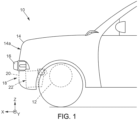
- a motor vehicle comprising a body and a cooling module as described above, the bodywork defining at least one cooling bay, the cooling module being arranged opposite the at least one cooling bay.
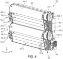
- the cooling module 22 is more clearly visible on the figures 2 to 4 .
- the cooling module 22 comprises a ventilation device 24 associated with at least one heat exchanger 26.
- the ventilation device 24 comprises at least one tangential fan, or more generally a tangential turbomachine, which draws in a flow of air in contact with heat or heat exchangers 26.
- the cooling module 24 comprises two tangential turbomachines 28-1, 28-2, detailed below.
- the cooling module 22 essentially comprises a housing or frame 30 forming an internal air channel.
- the frame 30 makes it possible to house at least one tangential turbomachine.
- a rear part of the frame 30 forms in particular here the volute 30-1, 30-2 of a tangential turbomachine 28-1, 28-2.
- the heat exchanger(s) 26 is/are arranged in the internal air channel.
- Each tangential turbomachine 28-1, 28-2 comprises a rotor 32-1, 32-2.
- the rotor here consists of a turbine 32-1, 32-2, more precisely a tangential propeller or bladed wheel.
- Each turbine 32-1, 32-2 has a cylindrical shape.
- Each turbine 32-1, 32-2 advantageously comprises several stages of blades (or blades).
- Each turbine 32-1, 32-2 is rotatably mounted around an associated rotation axis A32-1, A32-2.
- Each turbine 32-1, 32-2 is rotated by an associated motor 33-1, 33-2.
- all of the heat exchangers 26 delimit a surface S, called the working surface, a section of which is substantially rectangular in a plane (Y, Z).
- the Y direction corresponds to a horizontal direction, more preferably transverse, while the Z direction corresponds to a vertical direction, when the module is installed in the motor vehicle.
- the surface S is delimited by two opposite end edges 38, 39 extending in the direction Y, called length, and by two other opposite end edges 40, 41, in the direction Z, called height.
- the surface S corresponds to the rectangle defined by the exchanger 26, or if several exchangers are present, by the largest heat exchanger. However, it is also possible to juxtapose several exchangers vertically and/or horizontally, in which case the height of the surface S is the sum of the heights of the vertically juxtaposed (superimposed) exchangers, and the length of the surface S is the sum of the lengths of the horizontally juxtaposed exchangers.
- the first and second turbomachines 28-1 and 28-2 are mounted parallel to each other, that is to say that the air flow F1 ejected from the first turbine 32-1 of the first turbomachine 28-1 is distinct from the air flow F2 ejected from the second turbine 32-2 of the second turbomachine 28-2. In other words, the air flow F1 ejected from the first turbine 32-1 does not pass through the second turbine 32-2 and vice versa.
- the axes of rotation A32-1, A32-2 are parallel to the Y direction.
- the two turbines 32-1, 32-2 are thus mounted horizontally, in this case in a transverse direction.
- the axes of rotation A32-1, A32-2 can be vertical, i.e. parallel to the Z axis.
- the volute 30-1 of the first turbomachine 28-1 comprises a first air guide portion 44-1 around the first turbomachine 32-1 to a first outlet 46-1 of the air from the module 22.
- the first air guide portion 44-1 advantageously comprises a wall in the form of a truncated spiral.
- volute 30-2 of the second turbomachine 28-2 comprises a second air guide portion 44-2 around the second turbomachine 32-2 to an air outlet from the module 22, referenced 46-2.
- the second guide portion 44-2 advantageously comprises a wall in the form of a truncated spiral.
- the two outlets 46-1, 46-2 are arranged opposite each other, oriented substantially in the same direction. This makes it possible to reduce the acoustic waves generated by the cooling module 22, compared to a configuration where the two outlets face each other and are oriented in opposite directions.
- the illustrated configuration ensures that the air distribution of a first air flow F1 from the first turbomachine 28-1 via the associated first outlet 46-1 is substantially the same direction and in particular in the same direction as the distribution of a second air flow F2 from the second turbomachine 28-2 via the associated second outlet 46-2.
- the first and second air flows F1 and F2 are substantially vertical, and oriented downwards.
- a grid (not shown in the figures) is fixed to each of the outlets 46-1, 46-2.
- Such a grid can in particular prevent projections from entering the housing receiving the turbine 32-1, 32-2 and damaging this turbine 32-1, 32-2.
- the axis of rotation A32-1 of the first turbomachine 28-1 is arranged substantially opposite the longitudinal edge 38 upper surface S and the rotation axis A32-2 of the second turbomachine 28-2 is arranged in the middle of the height of the surface S.
- turbomachines 28-1, 28-2 are positions so as to dedicate them to respective exchangers 26.
- Other relative positions of turbomachines 28-1, 28-2 are also possible.
- the axis of rotation A32-2 of the second turbomachine 28-2 is arranged in an area between one fifth and four fifths of the height, preferably between one third and two thirds of said height, of the working surface S.
- the module 22 is provided with air guide means 50-1, 50-2 associated with each turbomachine 28-1, 28-2 (these means are removed on the Figure 2 for the purpose of visibility of interchange 26).
- Each air guide means 50-1, 50-2 comprises a plurality of flaps 52-1, 52-2.
- Each plurality of flaps 52-1, 52-2 is pivotally mounted between a closed position, illustrated in Figure 4 , in which the flaps 52-1, 52-2 close a respective opening 51-1, 51-2 formed by the frame 30 of the cooling module 22, and at least one open position, in which the flaps 52-1, 52-2 allow at least part of the air flow to pass through the associated opening 51-1, 51-2. In the closed position of the flaps 52-1, 52-2, these allow the created air flow to be directed towards the associated turbomachine 28-1, 28-2.
- the airflow is thus “diverted” from the turbomachine 28-1, 28-2.
- the open position is particularly advantageous when the vehicle is traveling at high speed, in which case it is possible to shut down the turbomachines 28-1, 28-2.
- the number of flaps 52-1 associated with the first turbomachine 28-1 may be identical or on the contrary different from the number of flaps 52-2 associated with the second turbomachine 28-2, depending on the respective position of the turbomachines 28-1, 28-2, in particular.
- Each plurality of flaps 52-1, 52-2 is associated with a respective actuator 54-1, 54-2.
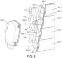
- An actuator 54-1 is described in more detail below, with reference to the figures 5 And 6 , it being understood that the actuator 54-2 may be identical.
- the actuator 54-1 firstly comprises an electric motor 56-1 whose output shaft drives a first flap 52-1 in rotation.
- the actuator 54-1 also comprises a connecting rod 58-1, the connecting rod 58-1 connecting together the first flap 52-1, driven in rotation by the output shaft of the electric motor 56-1, to the other flaps 52-1 of the plurality of flaps 52-1, such that the rotation of the first flap 52-1 is transmitted to the other flaps 52-1 of the plurality of flaps 52-1.
- each flap 52-1 comprises, at a first end, a cam 60-1.
- the axis of each cam 60-1 corresponds to the axis A52-1 of rotation of the associated flap 52-1.
- the cams 60-1 associated with the different flaps 52-1 are connected together by the connecting rod 58-1.
- the connecting rod 58-1 comprises a lug associated with each cam 60-1, received in a complementary housing formed in the cam 60-1, such that the lug received in the housing can pivot relative to the cam 60-1.
- the cam 60-1 associated with the first flap 52-1 is driven in rotation by the output shaft of the electric motor 56-1, either directly or via a reduction gear.
- the attachment point of the connecting rod 58-1 on each cam 60-1 is offset relative to the axis A52-1 of rotation of the associated flap 52-1.
- each flap 52-1 has a stud 62-1 received in a complementary housing 64-1 formed on a first upright 66-1 of the actuator 54-1.
- the first upright 66-1 may be formed in whole or in part by the housing 30 of the cooling module 22.
- the stud 62-1 and the complementary housing 64-1 are for example cylindrical, of circular section.
- the cams 60-1 are also received in complementary housings, to guide their rotation around the axis A52-1 of rotation of the associated flap 52-1.
- the housings are formed in a second upright 68-1.
- the second upright 68-1 may be formed in whole or in part by the housing 30 of the cooling module 22.
- the rotation F3, F4 of the first flap 52-1 is caused around its axis of rotation A52-1.
- the rotation F3, F4 of this first flap 52-1 causes the rotation of the associated cam 60-1, which in turn causes the displacement F5, F6, here vertical, of the connecting rod 58-1.
- the displacement F5, F6 of the connecting rod 58-1 causes the rotation of the other cams 60-1 and, consequently, of the other flaps 52-1 of the plurality of flaps 52-1.
- each flap 52-1 has a rib 70-1 along a first longitudinal side and a groove 72-1 of a shape complementary to the rib 70-1, along a second longitudinal side, such that the rib 70-1 of a first flap 52-1 is received in the groove 72-1 of a second neighboring flap 52-1 in the closed position of the flaps 52-1.
- each flap 52-1 may be tubular.
- the face of a flap 52-1 intended to be oriented towards the heat exchanger(s) 26 is substantially flat.
- the flat faces of the flaps 52-1 are aligned in the closed position of the flaps 52-1, to form a substantially flat surface for guiding the air flow. This makes it possible to limit the pressure losses of the air flow.
- the opposite face of the flaps 52-1 is preferably curved.
- each flap 52-1, 52-2 can be pivoted over an angular range of amplitude between 90° and 110°, preferably of amplitude 102.5°.
- One of the two extreme positions of the flaps 52-1 corresponds here to the closed position of the flaps 52-1, in which the aligned flat faces of the flaps 52-1 form an angle ⁇ between 5° and 20°, preferably substantially equal to 12.5° with an air inlet surface S2, normal to the air flow entering the ventilation device 24.
- the other of the two extreme positions of the flaps 52-1 corresponds to a position of the flaps 52-1 in which the flat surfaces of the flaps 52-1 extend substantially horizontally, that is to say substantially parallel to the air flow entering the ventilation device 24. In this position, the resistance of the flaps 52-1, 52-2 to the air flow passing through the associated opening 51-1, 51-2 is minimized.
Landscapes
- Engineering & Computer Science (AREA)
- Mechanical Engineering (AREA)
- General Engineering & Computer Science (AREA)
- Chemical & Material Sciences (AREA)
- Combustion & Propulsion (AREA)
- Transportation (AREA)
- Cooling, Air Intake And Gas Exhaust, And Fuel Tank Arrangements In Propulsion Units (AREA)
Description
- L'invention se rapporte à un module de refroidissement pour véhicule automobile, à turbomachine tangentielle. L'invention vise également un véhicule automobile muni d'un tel module de refroidissement.
- Les véhicules à moteur, qu'ils soient à combustion ou électriques, ont besoin d'évacuer les calories que génère leur fonctionnement et sont pour cela équipés d'échangeurs de chaleur. Un échangeur de chaleur de véhicule automobile comprend généralement des tubes, dans lesquels un fluide caloporteur est destiné à circuler, notamment un liquide tel que l'eau, et des éléments d'échange de chaleur reliés à ces tubes, souvent désignés par le terme « ailettes » ou « intercalaires ». Les ailettes permettent d'augmenter la surface d'échange entre les tubes et l'air ambiant.
- Toutefois, afin d'augmenter encore l'échange de chaleur entre le fluide caloporteur et l'air ambiant, il est fréquent qu'un dispositif de ventilation soit utilisé en sus, pour générer ou accroitre un flux d'air dirigé vers les tubes et les ailettes.
- De façon connue, un tel dispositif de ventilation comprend un ventilateur à hélice.
- Le flux d'air généré par les pales d'un tel ventilateur est turbulent, notamment en raison de la géométrie circulaire de l'hélice, et n'atteint en général qu'une partie seulement de la surface de l'échangeur de chaleur (zone circulaire de l'échangeur faisant face à l'hélice du ventilateur). L'échange de chaleur ne se fait donc pas de façon homogène sur toute la surface des tubes et des ailettes.
- En outre, lorsque la mise en marche du ventilateur ne s'avère pas nécessaire (typiquement lorsque l'échange de chaleur avec de l'air ambiant non accéléré suffit à refroidir le fluide caloporteur circulant dans l'échangeur), les pales obstruent en partie l'écoulement de l'air ambiant vers les tubes et les ailettes, ce qui gêne la circulation d'air vers l'échangeur et limite ainsi l'échange de chaleur avec le fluide caloporteur.
- Un tel ventilateur est en outre relativement encombrant, à cause notamment des dimensions nécessaires de l'hélice pour obtenir un refroidissement moteur effectif, ce qui rend long et délicat son intégration dans un véhicule automobile.
- Des exemples de dispositif de ventilation pour module de refroidissement de véhicule automobile comprenant une turbomachine tangentielle sont montrés dans les documents
DE102008020310A1 etDE102017203858A1 . - Le but de l'invention est de remédier au moins partiellement à ces inconvénients.
- À cet effet, l'invention a pour objet un dispositif de ventilation pour module de refroidissement de véhicule automobile, comprenant :
- au moins une turbomachine tangentielle comprenant une roue à aubes et un moteur pour entraîner en rotation la roue à aubes,
- au moins un cadre formant un logement de réception apte à recevoir la roue à aubes,
- une pluralité de volets montés pivotant par rapport au cadre, la pluralité de volets étant adaptée à sélectivement obturer une ouverture à travers le cadre, et
- un actionneur pour commander le pivotement de la pluralité de volets, caractérisé en ce que;
- ledit actionneur comprenant :
- un moteur électrique dont l'arbre de sortie entraine en rotation l'un parmi la pluralité de volets ;
- au moins une bielle reliant ledit un volet à l'autre ou aux autres volet/s de la pluralité de volets, de telle sorte que la rotation dudit un volet soit transmise à l'autre ou aux autres volet/s; et en ce que;
- dans la position d'obturation de l'ouverture par les volets, les volets forment une surface sensiblement plane formant, avec une surface d'entrée d'air normale au flux d'air en entrée du dispositif de ventilation, un angle compris entre 5 et 20°, de préférence sensiblement égal à 12,5°.
- Ainsi, avantageusement, on met en œuvre au moins une turbomachine tangentielle qui permet d'obtenir un flux d'air mieux réparti sur un ou plusieurs échangeurs de forme générale rectangulaire.
- En outre, la présence de volets permettant de sélectivement obturer une ouverture dans le cadre, permet d'augmenter le flux d'air traversant le ou les échangeurs de chaleur, lorsque la ou les turbomachines sont éteintes et que le flux d'air est produit par la vitesse du véhicule se déplaçant.
- Enfin, l'actionneur décrit ci-dessus est simple à réaliser et particulièrement robuste. Il permet un commandement synchronisé de la rotation des volets.
- De préférence, le module de refroidissement comporte une ou plusieurs des caractéristiques suivantes, prises seules ou en combinaison :
- chaque volet présente à une première extrémité une came, les cames des volets étant reliées ensemble par ladite au moins une bielle ;
- chaque volet présente à une deuxième extrémité un téton reçu pivotant dans un logement de réception dans le cadre ;
- les volets sont tubulaires, les volets présentant une face sensiblement plane et une face opposée courbe, les faces sensiblement plane des volets étant destinées à être alignées dans la position d'obturation de l'ouverture à travers le cadre, par les volets ;
- les volets présentent un nervure longitudinale sur un premier côté longitudinal et une rainure longitudinale sur un deuxième côté longitudinale, la rainure et la nervure étant de formes complémentaires ;
- les volets sont configurés pour pouvoir pivoter sur une plage angulaire d'amplitude comprise entre 90° et 110°, de préférence d'amplitude égale à 102,5° ; et
- chaque volet présente un joint d'étanchéité, notamment surmoulé sur le volet ;
- le dispositif de ventilation comprend en outre une grille au niveau d'une sortie d'air formée par le cadre.
- Selon un autre aspect, il est décrit un module de refroidissement pour véhicule automobile, en particulier pour véhicule automobile à moteur électrique, comprenant au moins un échangeur thermique et au moins un dispositif de ventilation tel que décrit ci-avant dans toutes ses combinaisons, apte à créer un flux d'air au contact du au moins un échangeur thermique.
- Selon un autre aspect, il est proposé un véhicule automobile, comprenant une carrosserie et un module de refroidissement tel que décrit précédemment, la carrosserie définissant au moins une baie de refroidissement, le module de refroidissement étant disposé en regard de la au moins une baie de refroidissement.
- D'autres caractéristiques, détails et avantages de l'invention apparaîtront à la lecture de la description détaillée ci-après, et à l'analyse des dessins annexés, sur lesquels :
- [
Fig. 1 ] représente schématiquement la partie avant d'un véhicule automobile, vu de côté ; - [
Fig. 2 ] est une vue schématique en perspective d'un module de refroidissement pouvant être mis en œuvre dans le véhicule automobile de lafigure 1 , dont les volets ont été retirés ; - [
Fig. 3 ] est une vue de côté du module de refroidissement de lafigure 2 ; - [
Fig. 4 ] est une analogue à lafigure 2 , dont les volets sont en position de fermeture d'une ouverture dans le boîtier du module de refroidissement ; - [
Fig. 5 ] est une éclatée d'un détail du module de refroidissement desfigures 2 à 4 ; - [
Fig. 6 ] est une éclatée d'un autre détail du module de refroidissement desfigures 2 à 4 ; - [
Fig. 7 ] est une vue en coupe longitudinale d'une partie du module de refroidissement desfigures 2 à 4 ; et - [
Fig. 8 ] est une vue en coupe d'un volet du module de refroidissement desfigures 2 à 4 . - Dans la suite de la description, les éléments identiques ou de fonction identique portent le même signe de référence. À fin de concision de la présente description, ces éléments ne sont pas décrits en détails dans chaque mode de réalisation. Au contraire, seules les différences entre les variantes de réalisation sont décrites en détails.
- La
figure 1 illustre de manière schématique la partie avant d'un véhicule automobile 10 à moteur 12. Le véhicule 10 comporte notamment une carrosserie 14 et un pare-chocs 16 portés par un châssis (non représenté) du véhicule automobile 10. La carrosserie 14 définit une baie de refroidissement 18, c'est-à-dire une ouverture à travers la carrosserie 14. La baie de refroidissement 18 peut être unique comme dans l'exemple illustré. Alternativement cependant, la carrosserie 14 peut définir une pluralité de baies de refroidissement. Ici, la baie de refroidissement 18 se trouve en partie basse de la face avant 14a de la carrosserie 14. Dans l'exemple illustré, la baie de refroidissement 18 est située sous le pare-chocs 16. Une grille 20 peut être disposée dans la baie de refroidissement 18 pour éviter que des projectiles puissent traverser la baie de refroidissement 18. Un module de refroidissement 22 est disposé en vis-à-vis de la baie de refroidissement 18. La grille 20 permet notamment de protéger ce module de refroidissement 22. - Le module de refroidissement 22 est plus nettement visible sur les
figures 2 à 4 . - Le module de refroidissement 22 comprend un dispositif de ventilation 24 associé à au moins un échangeur thermique 26.
- Comme il ressort des figures, le dispositif de ventilation 24 comprend au moins un ventilateur tangentiel, ou plus généralement une turbomachine tangentielle, qui aspire un flux d'air au contact de chaleur ou des échangeurs de chaleur 26. Sur l'exemple illustré, le module de refroidissement 24 comprend deux turbomachines tangentielles 28-1, 28-2, détaillées ci-après.
- Tel qu'illustré, le module de refroidissement 22 comporte essentiellement un boîtier ou cadre 30 formant un canal interne d'air. Le cadre 30 permet de loger au moins une turbomachine tangentielle. Une partie arrière du cadre 30 forme notamment ici la volute 30-1, 30-2 d'une turbomachine tangentielle 28-1, 28-2. Le ou les échangeurs thermiques 26 est/sont disposé/s dans le canal interne d'air.
- Chaque turbomachine tangentielle 28-1, 28-2 comprend un rotor 32-1, 32-2. Le rotor est ici constitué d'une turbine 32-1, 32-2, plus précisément d'une hélice tangentielle ou roue à aubes. Chaque turbine 32-1, 32-2 a une forme cylindrique. Chaque turbine 32-1, 32-2 comporte avantageusement plusieurs étages de pales (ou aubes). Chaque turbine 32-1, 32-2 est montée rotative autour d'un axe de rotation A32-1, A32-2 associé. Chaque turbine 32-1, 32-2 est entrainée en rotation par un moteur 33-1, 33-2 associé.
- Sur la
figure 2 , l'ensemble des échangeurs thermiques 26 délimitent une surface S, appelée surface de travail, dont une section est sensiblement rectangulaire dans un plan (Y, Z). - De préférence, la direction Y correspond à une direction horizontale, de préférence encore transversale, tandis que la direction Z correspond à une direction verticale, quand le module est installé dans le véhicule automobile.
- La surface S est délimitée par deux bords d'extrémité opposés 38, 39 s'étendant selon la direction Y, dite longueur, et par deux autres bords d'extrémité opposés 40, 41, selon la direction Z, dite hauteur.
- La surface S correspond au rectangle défini par l'échangeur 26, ou si plusieurs échangeurs sont présents, par le plus grand échangeur thermique. Néanmoins, il est également possible de juxtaposer plusieurs échangeurs verticalement et/ou horizontalement, auquel cas la hauteur de la surface S est la somme des hauteurs des échangeurs juxtaposés verticalement (superposés), et la longueur de la surface S est la somme des longueurs des échangeurs juxtaposés horizontalement.
- Les première et deuxième turbomachines 28-1 et 28-2 sont montées parallèlement l'une à l'autre, c'est-à-dire que le flux d'air F1 éjecté de la première turbine 32-1 de la première turbomachine 28-1 est distinct du flux d'air F2 éjecté de la deuxième turbine 32-2 de la deuxième turbomachine 28-2. En d'autres termes, le flux d'air F1 éjecté de la première turbine 32-1 ne traverse pas la deuxième turbine 32-2 et réciproquement.
- Sur les figures, les axes de rotation A32-1, A32-2 sont parallèles à la direction Y. Les deux turbines 32-1, 32-2 sont ainsi montées horizontalement, en l'espèce selon une direction transversale. Alternativement, les axes de rotation A32-1, A32-2 peuvent être verticaux, c'est-à-dire parallèles à l'axe Z.
- Comme également visible sur les figures, la volute 30-1 de la première turbomachine 28-1 comprend une première portion de guidage 44-1 d'air autour de la première turbomachine 32-1 jusqu'à une première sortie 46-1 de l'air hors du module 22. De manière connue, la première portion de guidage d'air 44-1 comprend avantageusement une paroi en forme de spirale tronquée.
- De manière analogue, la volute 30-2 de la deuxième turbomachine 28-2 comprend une deuxième portion de guidage 44-2 d'air autour de la deuxième turbomachine 32-2 jusqu'à une sortie de l'air hors du module 22, référencée 46-2. La deuxième portion de guidage 44-2 comprend avantageusement une paroi en forme de spirale tronquée.
- Selon le mode de réalisation illustré, les deux sorties 46-1, 46-2 sont disposées en regard l'une de l'autre, orientées sensiblement dans un même sens. Ceci permet de réduire les ondes acoustiques générées par le module de refroidissement 22, par rapport à une configuration où les deux sorties se font face et sont orientées dans des sens opposés.
- La configuration illustrée assure que la répartition d'air d'un premier flux d'air F1 issu de la première turbomachine 28-1 via la première sortie 46-1 associée est sensiblement la même direction et en particulier dans le même sens que la répartition d'un deuxième flux d'air F2 issu de la deuxième turbomachine 28-2 via la deuxième sortie 46-2 associée. En l'espèce, les premier et deuxième flux d'air F1 et F2 sont sensiblement verticaux, et orientés vers le bas.
- Ainsi, quand le véhicule se trouve dans un environnement humide voire mouillé, comme en cas de pluie ou de passage à gué, la turbomachine 28-1, 28-2 est protégée, puisque l'eau ne peut pas être stockée dans la volute 30-1, 30-2 mais au contraire est évacuée par la sortie 46-1, 46-2. De ce fait, toute submersion du module de refroidissement 22 est évitée.
- Avantageusement, une grille (non représentée sur les figures) est fixée à chacune des sorties 46-1, 46-2. Une telle grille peut notamment permettre d'éviter que des projections pénètrent dans le logement recevant la turbine 32-1, 32-2 et endommagent cette turbine 32-1, 32-2.
- Comme il ressort également des figures, l'axe de rotation A32-1 de la première turbomachine 28-1 est disposé sensiblement en face du bord longitudinal 38 supérieure de la surface S et l'axe de rotation A32-2 de la deuxième turbomachine 28-2 est disposé au milieu de la hauteur de la surface S.
- Néanmoins, selon la configuration des échangeurs thermiques et/ou la puissance de refroidissement requise pour chaque échangeur, il est possible de positionner les turbomachines 28-1, 28-2 de sorte à les dédier à des échangeurs 26 respectifs. D'autres positions relatives de turbomachines 28-1, 28-2 sont également possibles.
- Avantageusement, l'axe de rotation A32-2 de la deuxième turbomachine 28-2 est disposé dans une zone comprise entre un cinquième et quatre cinquième de la hauteur, de préférence entre un tiers et deux tiers de ladite hauteur, de la surface de travail S.
- Comme illustré sur les
figures 3 et4 , le module 22 est muni de moyens de guidage d'air 50-1, 50-2 associés à chaque turbomachine 28-1, 28-2 (ces moyens sont retirés sur lafigure 2 à fin de visibilité de l'échangeur 26). - Chaque moyen de guidage d'air 50-1, 50-2 comprend une pluralité de volets 52-1, 52-2. Chaque pluralité de volets 52-1, 52-2 est montée pivotante entre une position de fermeture, illustrée à la
figure 4 , dans laquelle les volets 52-1, 52-2 obturent une ouverture 51-1, 51-2 respective formée par le cadre 30 du module de refroidissement 22, et au moins une position d'ouverture, dans laquelle les volets 52-1, 52-2 permettent à au moins une partie du flux d'air de traverser l'ouverture 51-1, 51-2 associée. Dans la position de fermeture des volets 52-1, 52-2, ceux-ci permettent de diriger le flux d'air créé vers la turbomachine associée 28-1, 28-2. Au contraire, une position ouverte des volets 52-1, 52-2, atteinte généralement alors que la turbomachine 28-1, 28-2 associée est éteinte, permet de diriger au moins une partie du flux d'air créé par exemple par la vitesse du véhicule sur lequel le module de refroidissement 22 est monté, à travers une ouverture respective 51-1, 51-2 dans le cadre 30, sans passer par la turbomachine associée 28-1, 28-2. On « dérive » ainsi le flux d'air de la turbomachine 28-1, 28-2. - La position d'ouverture est particulièrement avantageuse quand le véhicule roule à grande vitesse, auquel cas il est possible de mettre les turbomachines 28-1, 28-2 à l'arrêt.
- Le nombre de volets 52-1 associés à la première turbomachine 28-1 peut être identique ou au contraire différent du nombre de volets 52-2 associés à la deuxième turbomachine 28-2, selon la position respective des turbomachines 28-1, 28-2, notamment.
- Chaque pluralité de volets 52-1, 52-2 est associée à un actionneur 54-1, 54-2 respectif. Un actionneur 54-1 est décrit plus en détail ci-après, en regard des
figures 5 et6 , étant entendu que l'actionneur 54-2 peut être identique. - Comme illustré sur les
figures 5 et6 , l'actionneur 54-1 comprend tout d'abord un moteur électrique 56-1 dont l'arbre de sortie entraîne en rotation un premier volet 52-1. L'actionneur 54-1 comprend également une bielle 58-1, la bielle 58-1 reliant ensemble le premier volet 52-1, entrainé en rotation par l'arbre de sortie du moteur électrique 56-1, aux autres volets 52-1 de la pluralité de volets 52-1, de telle sorte que la rotation du premier volet 52-1 soit transmise aux autres volets 52-1 de la pluralité de volets 52-1. - Plus précisément, chaque volet 52-1 comprend, à une première extrémité, une came 60-1. L'axe de chaque came 60-1 correspond à l'axe A52-1 de rotation du volet 52-1 associé. Les cames 60-1 associés aux différents volets 52-1 sont reliées ensemble par la bielle 58-1. Par exemple, la bielle 58-1 comprend un ergot associé à chaque came 60-1, reçu dans un logement complémentaire formé dans la came 60-1, de telle sorte que l'ergot reçu dans le logement puisse pivoter par rapport la came 60-1. La came 60-1 associée au premier volet 52-1 est entrainée en rotation par l'arbre de sortie du moteur électrique 56-1, soit directement, soit par l'intermédiaire d'un engrenage réducteur. Le point de fixation de la bielle 58-1 sur chaque came 60-1 est décalé par rapport à l'axe A52-1 de rotation du volet 52-1 associé.
- Comme visible sur la
figure 5 notamment, l'extrémité opposée à la came 60-1 de chaque volet 52-1 présente ici un téton 62-1 reçu dans un logement 64-1 complémentaire formé sur un premier montant 66-1 de l'actionneur 54-1. Le premier montant 66-1 peut être formé en tout ou partie par le boîtier 30 du module de refroidissement 22. Le téton 62-1 et le logement 64-1 complémentaire sont par exemple cylindriques, de section circulaire. - Les cames 60-1 sont également reçues dans des logements complémentaires, pour guider leur rotation autour de l'axe A52-1 de rotation du volet 52-1 associé. Les logements sont formés dans un deuxième montant 68-1. Le deuxième montant 68-1 peut être formé en tout ou partie par le boîtier 30 du module de refroidissement 22.
- Comme illustré schématiquement sur la
figure 6 , en fonction du sens de rotation du moteur 56-1, on provoque la rotation F3, F4 du premier volet 52-1 autour de son axe de rotation A52-1. La rotation F3, F4 de ce premier volet 52-1 provoque la rotation de la came 60-1 associée, qui engendre à son tour le déplacement F5, F6, ici vertical, de la bielle 58-1. Le déplacement F5, F6 de la bielle 58-1 provoque la rotation des autres cames 60-1 et, par conséquent, des autres volets 52-1 de la pluralité de volets 52-1. - Afin d'améliorer l'étanchéité entre les volets 52-1 en position de fermeture, un joint - non illustré sur les figures - peut être surmoulé sur les volets. Alternativement ou au surplus, chaque volet 52-1 présente une nervure 70-1 le long d'un premier côté longitudinal et une rainure 72-1 de forme complémentaire à la nervure 70-1, le long d'un deuxième côté longitudinal, de telle sorte que la nervure 70-1 d'un premier volet 52-1 est reçue dans la rainure 72-1 d'un deuxième volet 52-1 voisin en position de fermeture des volets 52-1.
- Comme illustré en particulier sur la
figure 8 , chaque volet 52-1 peut être tubulaire. De préférence, la face d'un volet 52-1 destinée à être orientée vers le ou les échangeur/s thermique/s 26 est sensiblement plane. Les faces planes des volets 52-1 sont alignées dans la position de fermeture des volets 52-1, pour former une surface sensiblement plane de guidage du flux d'air. Ceci permet de limiter les pertes de charges du flux d'air. La face opposée des volets 52-1 est de préférence courbe. - En outre, les
figures 7 et 8 illustrent également que chaque volet 52-1, 52-2 peut être pivoté sur une plage angulaire d'amplitude comprise entre 90° et 110 °, de préférence d'amplitude 102,5 °. L'une des deux positions extrémales des volets 52-1 correspond ici à la position de fermeture des volets 52-1, dans laquelle les faces planes des volets 52-1 alignées forment un angle α compris entre 5° et 20 °, de préférence sensiblement égal à 12,5 ° avec une surface S2 d'entrée d'air, normale au flux d'air en entrée du dispositif de ventilation 24. L'autre des deux positions extrémales des volets 52-1 correspond à une position des volets 52-1 dans laquelle les surfaces planes des volets 52-1 s'étendent sensiblement horizontalement, c'est-à-dire sensiblement parallèlement au flux d'air en entrée du dispositif de ventilation 24. Dans cette position, on minimise la résistance des volets 52-1, 52-2 au flux d'air traversant l'ouverture 51-1, 51-2 associée. - L'invention ne se limite pas au seul exemple décrit ci-avant. Au contraire, l'invention est susceptible de nombreuses variantes accessibles à l'homme de l'art telles que définies par les revendications annexées.
- Notamment, dans l'exemple illustré, le dispositif de ventilation comporte deux turbomachines. Alternativement, le dispositif de ventilation peut comporter une seule turbomachine ou plus de deux turbomachines.
- Également, dans l'exemple illustré, les volets pivotent autour d'un axe parallèle à l'axe de rotation des turbomachines. Alternativement, cependant, le ou les volets peut/peuvent pivoter autour d'un axe perpendiculaire à l'axe de rotation de la ou des turbomachines.
Claims (9)
- Dispositif de ventilation (24) pour module de refroidissement (22) de véhicule automobile (10), comprenant :- au moins une turbomachine tangentielle (28-1 ; 28-2) comprenant une roue à aubes (32-1 ; 32-2) et un moteur (33-1 ; 33-2) pour entraîner en rotation la roue à aubes (32-1 ; 32-2),- au moins un cadre (30) formant un logement (30-1 ; 30-2) de réception apte à recevoir la roue à aubes (32-1 ; 32-2),- une pluralité de volets (52-1 ; 52-2) montés pivotant par rapport au cadre (30), la pluralité de volets (52-1 ; 52-2) étant adaptée à sélectivement obturer une ouverture (51-1 ; 51-2) à travers le cadre (30), et- un actionneur (54-1 ; 54-2) pour commander le pivotement de la pluralité de volets (52-1 ; 52-2), caractérisé en ce que;ledit actionneur (54-1 ; 54-2) comprenant :- un moteur électrique (56-1 ; 56-2) dont l'arbre de sortie entraine en rotation l'un parmi la pluralité de volets (52-1 ; 52-2) ;- au moins une bielle (58-1) reliant ledit un volet (52-1 ; 52-2) à l'autre ou aux autres volet/s (52-1 ; 52-2) de la pluralité de volets (52-1 ; 52-2), de telle sorte que la rotation dudit un volet (52-1 ; 52-2) soit transmise à l'autre ou aux autres volet/s (52-1 ; 52-2),et en ce que dans la position d'obturation de l'ouverture (51-1 ; 51-2) par les volets (52-1 ; 52-2), les volets (52-1 ; 52-2) forment une surface sensiblement plane formant, avec une surface (S2) d'entrée d'air normale au flux d'air en entrée du dispositif de ventilation (22), un angle (α) compris entre 5 et 20°, de préférence sensiblement égal à 12,5°.
- Dispositif de ventilation selon la revendication 1, dans lequel chaque volet (52-1 ; 52-2) présente à une première extrémité une came (60-1), les cames (60-1) des volets (52-1 ; 52-2) étant reliées ensemble par ladite au moins une bielle (58-1).
- Dispositif de ventilation selon la revendication 2, dans lequel chaque volet (52-1 ; 52-2) présente à une deuxième extrémité un téton (62-1) reçu pivotant dans un logement de réception (64-1) dans le cadre (30).
- Dispositif de ventilation selon l'une des revendications 1 à 3, dans lequel les volets (52-1 ; 52-2) sont tubulaires, les volets (52-1 ; 52-2) présentant une face sensiblement plane et une face opposée courbe, les faces sensiblement plane des volets (52-1 ; 52-2) étant destinées à être alignées dans la position d'obturation de l'ouverture (51-1 ; 51-2) à travers le cadre (30), par les volets (52-1 ; 52-2).
- Dispositif de ventilation selon la revendication 4, dans lequel les volets (52-1 ; 52-2) présentent un nervure longitudinale (70-1) sur un premier côté longitudinal et une rainure (72-1) longitudinale sur un deuxième côté longitudinale, la rainure (70-1) et la nervure (72-1) étant de formes complémentaires.
- Dispositif de ventilation selon l'une quelconque des revendications précédentes, dans lequel les volets (52-1 ; 52-2) sont configurés pour pouvoir pivoter sur une plage angulaire d'amplitude comprise entre 90° et 110°, de préférence d'amplitude égale à 102,5°.
- Dispositif de ventilation selon l'une quelconque des revendications précédentes, dans lequel chaque volet (52-1 ; 52-2) présente un joint d'étanchéité, notamment surmoulé sur le volet (52-1 ; 52-2).
- Dispositif de ventilation selon l'une quelconque des revendications précédentes, comprenant en outre une grille au niveau d'une sortie d'air (46-1 ; 46-2) formée par le cadre (30).
- Module de refroidissement (22) pour véhicule automobile (10), en particulier pour véhicule automobile à moteur électrique, comprenant au moins un échangeur thermique (26) et au moins un dispositif de ventilation (24) selon l'une quelconque des revendications 1 à 8, apte à créer un flux d'air au contact du au moins un échangeur thermique (26).
Applications Claiming Priority (2)
| Application Number | Priority Date | Filing Date | Title |
|---|---|---|---|
| FR1909951A FR3100487B1 (fr) | 2019-09-10 | 2019-09-10 | Module de refroidissement pour véhicule automobile à turbomachine tangentielle |
| PCT/FR2020/051545 WO2021048493A1 (fr) | 2019-09-10 | 2020-09-08 | Module de refroidissement pour véhicule automobile à turbomachine tangentielle |
Publications (2)
| Publication Number | Publication Date |
|---|---|
| EP4028654A1 EP4028654A1 (fr) | 2022-07-20 |
| EP4028654B1 true EP4028654B1 (fr) | 2025-03-19 |
Family
ID=68425131
Family Applications (1)
| Application Number | Title | Priority Date | Filing Date |
|---|---|---|---|
| EP20780769.4A Active EP4028654B1 (fr) | 2019-09-10 | 2020-09-08 | Module de refroidissement pour véhicule automobile à turbomachine tangentielle |
Country Status (5)
| Country | Link |
|---|---|
| US (1) | US12344086B2 (fr) |
| EP (1) | EP4028654B1 (fr) |
| CN (1) | CN114514133A (fr) |
| FR (1) | FR3100487B1 (fr) |
| WO (1) | WO2021048493A1 (fr) |
Family Cites Families (15)
| Publication number | Priority date | Publication date | Assignee | Title |
|---|---|---|---|---|
| US4519343A (en) * | 1982-11-08 | 1985-05-28 | Aisin Seiki Kabushiki Kaisha | Engine cooling system |
| JP2005053464A (ja) * | 2003-07-24 | 2005-03-03 | Denso Corp | 車両の前端構造 |
| US7931104B2 (en) * | 2007-08-28 | 2011-04-26 | Caterpillar Paving Products Inc. | Machine having cooling system and method |
| DE102008020310B4 (de) * | 2008-04-23 | 2019-12-19 | Audi Ag | Kraftfahrzeug mit zwei Wärmetauschern |
| JP4993791B2 (ja) * | 2010-06-28 | 2012-08-08 | シャープ株式会社 | ファン、成型用金型および流体送り装置 |
| DE102010017636A1 (de) * | 2010-06-29 | 2011-12-29 | Aksys Gmbh | Kühlluftführungssystem für ein Fahrzeug |
| US20130068403A1 (en) * | 2011-09-21 | 2013-03-21 | Srg Global Inc. | Grille Shutter Seal |
| FR2997348B1 (fr) * | 2012-10-25 | 2016-07-01 | Valeo Systemes Thermiques | Volet d'obturation de ventilation pour automobile a faible signature aeraulique |
| GB2514377A (en) * | 2013-05-21 | 2014-11-26 | Johnson Electric Sa | Actuator with progressive gear |
| FR3010502B1 (fr) * | 2013-09-09 | 2016-04-29 | Valeo Systemes Thermiques | Volet d'obturation de ventilation pour automobile |
| JP2016135636A (ja) * | 2015-01-23 | 2016-07-28 | シロキ工業株式会社 | 車両用シャッター装置 |
| US10100707B2 (en) * | 2016-02-29 | 2018-10-16 | Montaplast of North America, Inc. | Active grille shutter and shutter subassembly for use with active grill shutters |
| DE102017203858A1 (de) * | 2017-03-09 | 2018-09-13 | Bayerische Motoren Werke Aktiengesellschaft | Kühlvorrichtung für ein Kraftfahrzeug, Lüfterzarge sowie eine die Kühlvorrichtung aufweisende Brennkraftmaschine |
| DE102017119098A1 (de) * | 2017-08-21 | 2019-02-21 | Geiger Automotive Gmbh | Innenliegende Antriebswelle |
| FR3078572B1 (fr) * | 2018-03-05 | 2021-05-21 | Valeo Systemes Thermiques | Levier pour un dispositif d'obturation de vehicule automobile |
-
2019
- 2019-09-10 FR FR1909951A patent/FR3100487B1/fr active Active
-
2020
- 2020-09-08 US US17/641,578 patent/US12344086B2/en active Active
- 2020-09-08 WO PCT/FR2020/051545 patent/WO2021048493A1/fr not_active Ceased
- 2020-09-08 CN CN202080071539.XA patent/CN114514133A/zh active Pending
- 2020-09-08 EP EP20780769.4A patent/EP4028654B1/fr active Active
Also Published As
| Publication number | Publication date |
|---|---|
| FR3100487A1 (fr) | 2021-03-12 |
| WO2021048493A1 (fr) | 2021-03-18 |
| US20220297532A1 (en) | 2022-09-22 |
| CN114514133A (zh) | 2022-05-17 |
| FR3100487B1 (fr) | 2021-08-06 |
| EP4028654A1 (fr) | 2022-07-20 |
| US12344086B2 (en) | 2025-07-01 |
Similar Documents
| Publication | Publication Date | Title |
|---|---|---|
| EP4291431B1 (fr) | Module de refroidissement pour véhicule automobile électrique ou hybride à turbomachine tangentielle | |
| FR3100584A1 (fr) | Dispositif de ventilation pour module de refroidissement de véhicule automobile | |
| EP3938633A1 (fr) | Module de refroidissement pour vehicule automobile electrique a turbomachine tangentielle | |
| WO2021048494A1 (fr) | Procédé de fabrication d'un dispositif de ventilation pour module de refroidissement de véhicule automobile à turbomachine tangentielle | |
| WO2022200168A1 (fr) | Module de refroidissement pour vehicule automobile electrique ou hybride | |
| WO2021123555A1 (fr) | Module de dispositif de ventilation pour module de refroidissement de véhicule automobile, dispositif de ventilation comportant un tel module et module de refroidissement pour véhicule automobile comprenant un tel dispositif de ventilation | |
| EP4028654B1 (fr) | Module de refroidissement pour véhicule automobile à turbomachine tangentielle | |
| EP4314511A1 (fr) | Module de refroidissement pour vehicule automobile electrique ou hybride | |
| WO2022254013A1 (fr) | Module de refroidissement pour véhicule automobile électrique ou hybride à turbomachine tangentielle à volute variable | |
| FR3100488A1 (fr) | Module de refroidissement pour véhicule automobile à deux turbomachines tangentielles et au moins un échangeur thermique | |
| EP3976408B1 (fr) | Module de refroidissement pour véhicule automobile électrique à turbomachine tangentielle | |
| WO2024056696A1 (fr) | Boîtier collecteur pour module de refroidissement d'un véhicule automobile électrique ou hybride à turbomachine tangentielle | |
| WO2024056697A1 (fr) | Boîtier collecteur pour module de refroidissement d'un véhicule automobile électrique ou hybride à turbomachine tangentielle | |
| FR3105371A1 (fr) | Module de refroidissement pour véhicule automobile à turbomachine tangentielle | |
| EP4028274A1 (fr) | Module de refroidissement pour véhicule automobile à turbomachine tangentielle | |
| WO2022106147A1 (fr) | Module de refroidissement pour véhicule automobile électrique ou hybride à turbomachine tangentielle avec échangeur de chaleur supplémentaire | |
| FR3115734A1 (fr) | Module de refroidissement pour véhicule automobile électrique ou hybride à turbomachine tangentielle | |
| WO2021123557A1 (fr) | Module de refroidissement pour véhicule automobile à turbomachine tangentielle | |
| WO2021123552A1 (fr) | Dispositif de ventilation pour module de refroidissement de véhicule automobile et module de refroidissement pour véhicule automobile comprenant un tel dispositif de ventilation | |
| WO2022200166A1 (fr) | Module de refroidissement pour vehicule automobile electrique ou hybride a turbomachine tangentielle | |
| WO2021123553A1 (fr) | Dispositif de ventilation pour module de refroidissement de véhicule automobile | |
| WO2024052488A1 (fr) | Boitier collecteur pour module de refroidissement d'un vehicule automobile electrique ou hybride a turbomachine tangentielle | |
| FR3141101A1 (fr) | Module de refroidissement d’un véhicule automobile électrique ou hybride à turbomachine tangentielle | |
| FR3105373A1 (fr) | Module de refroidissement pour véhicule automobile à turbomachine tangentielle |
Legal Events
| Date | Code | Title | Description |
|---|---|---|---|
| STAA | Information on the status of an ep patent application or granted ep patent |
Free format text: STATUS: UNKNOWN |
|
| STAA | Information on the status of an ep patent application or granted ep patent |
Free format text: STATUS: THE INTERNATIONAL PUBLICATION HAS BEEN MADE |
|
| PUAI | Public reference made under article 153(3) epc to a published international application that has entered the european phase |
Free format text: ORIGINAL CODE: 0009012 |
|
| STAA | Information on the status of an ep patent application or granted ep patent |
Free format text: STATUS: REQUEST FOR EXAMINATION WAS MADE |
|
| 17P | Request for examination filed |
Effective date: 20220228 |
|
| AK | Designated contracting states |
Kind code of ref document: A1 Designated state(s): AL AT BE BG CH CY CZ DE DK EE ES FI FR GB GR HR HU IE IS IT LI LT LU LV MC MK MT NL NO PL PT RO RS SE SI SK SM TR |
|
| DAV | Request for validation of the european patent (deleted) | ||
| DAX | Request for extension of the european patent (deleted) | ||
| P01 | Opt-out of the competence of the unified patent court (upc) registered |
Effective date: 20230528 |
|
| GRAP | Despatch of communication of intention to grant a patent |
Free format text: ORIGINAL CODE: EPIDOSNIGR1 |
|
| STAA | Information on the status of an ep patent application or granted ep patent |
Free format text: STATUS: GRANT OF PATENT IS INTENDED |
|
| INTG | Intention to grant announced |
Effective date: 20241010 |
|
| GRAS | Grant fee paid |
Free format text: ORIGINAL CODE: EPIDOSNIGR3 |
|
| GRAA | (expected) grant |
Free format text: ORIGINAL CODE: 0009210 |
|
| STAA | Information on the status of an ep patent application or granted ep patent |
Free format text: STATUS: THE PATENT HAS BEEN GRANTED |
|
| AK | Designated contracting states |
Kind code of ref document: B1 Designated state(s): AL AT BE BG CH CY CZ DE DK EE ES FI FR GB GR HR HU IE IS IT LI LT LU LV MC MK MT NL NO PL PT RO RS SE SI SK SM TR |
|
| REG | Reference to a national code |
Ref country code: GB Ref legal event code: FG4D Free format text: NOT ENGLISH |
|
| REG | Reference to a national code |
Ref country code: CH Ref legal event code: EP |
|
| REG | Reference to a national code |
Ref country code: IE Ref legal event code: FG4D Free format text: LANGUAGE OF EP DOCUMENT: FRENCH |
|
| REG | Reference to a national code |
Ref country code: DE Ref legal event code: R096 Ref document number: 602020047972 Country of ref document: DE |
|
| PG25 | Lapsed in a contracting state [announced via postgrant information from national office to epo] |
Ref country code: RS Free format text: LAPSE BECAUSE OF FAILURE TO SUBMIT A TRANSLATION OF THE DESCRIPTION OR TO PAY THE FEE WITHIN THE PRESCRIBED TIME-LIMIT Effective date: 20250619 |
|
| PG25 | Lapsed in a contracting state [announced via postgrant information from national office to epo] |
Ref country code: FI Free format text: LAPSE BECAUSE OF FAILURE TO SUBMIT A TRANSLATION OF THE DESCRIPTION OR TO PAY THE FEE WITHIN THE PRESCRIBED TIME-LIMIT Effective date: 20250319 |
|
| REG | Reference to a national code |
Ref country code: LT Ref legal event code: MG9D |
|
| PG25 | Lapsed in a contracting state [announced via postgrant information from national office to epo] |
Ref country code: NO Free format text: LAPSE BECAUSE OF FAILURE TO SUBMIT A TRANSLATION OF THE DESCRIPTION OR TO PAY THE FEE WITHIN THE PRESCRIBED TIME-LIMIT Effective date: 20250619 |
|
| PG25 | Lapsed in a contracting state [announced via postgrant information from national office to epo] |
Ref country code: HR Free format text: LAPSE BECAUSE OF FAILURE TO SUBMIT A TRANSLATION OF THE DESCRIPTION OR TO PAY THE FEE WITHIN THE PRESCRIBED TIME-LIMIT Effective date: 20250319 |
|
| PG25 | Lapsed in a contracting state [announced via postgrant information from national office to epo] |
Ref country code: LV Free format text: LAPSE BECAUSE OF FAILURE TO SUBMIT A TRANSLATION OF THE DESCRIPTION OR TO PAY THE FEE WITHIN THE PRESCRIBED TIME-LIMIT Effective date: 20250319 |
|
| PG25 | Lapsed in a contracting state [announced via postgrant information from national office to epo] |
Ref country code: GR Free format text: LAPSE BECAUSE OF FAILURE TO SUBMIT A TRANSLATION OF THE DESCRIPTION OR TO PAY THE FEE WITHIN THE PRESCRIBED TIME-LIMIT Effective date: 20250620 Ref country code: BG Free format text: LAPSE BECAUSE OF FAILURE TO SUBMIT A TRANSLATION OF THE DESCRIPTION OR TO PAY THE FEE WITHIN THE PRESCRIBED TIME-LIMIT Effective date: 20250319 |
|
| REG | Reference to a national code |
Ref country code: NL Ref legal event code: MP Effective date: 20250319 |
|
| REG | Reference to a national code |
Ref country code: AT Ref legal event code: MK05 Ref document number: 1777112 Country of ref document: AT Kind code of ref document: T Effective date: 20250319 |
|
| PG25 | Lapsed in a contracting state [announced via postgrant information from national office to epo] |
Ref country code: NL Free format text: LAPSE BECAUSE OF FAILURE TO SUBMIT A TRANSLATION OF THE DESCRIPTION OR TO PAY THE FEE WITHIN THE PRESCRIBED TIME-LIMIT Effective date: 20250319 |
|
| PG25 | Lapsed in a contracting state [announced via postgrant information from national office to epo] |
Ref country code: SE Free format text: LAPSE BECAUSE OF FAILURE TO SUBMIT A TRANSLATION OF THE DESCRIPTION OR TO PAY THE FEE WITHIN THE PRESCRIBED TIME-LIMIT Effective date: 20250319 |
|
| PG25 | Lapsed in a contracting state [announced via postgrant information from national office to epo] |
Ref country code: SM Free format text: LAPSE BECAUSE OF FAILURE TO SUBMIT A TRANSLATION OF THE DESCRIPTION OR TO PAY THE FEE WITHIN THE PRESCRIBED TIME-LIMIT Effective date: 20250319 |
|
| PG25 | Lapsed in a contracting state [announced via postgrant information from national office to epo] |
Ref country code: ES Free format text: LAPSE BECAUSE OF FAILURE TO SUBMIT A TRANSLATION OF THE DESCRIPTION OR TO PAY THE FEE WITHIN THE PRESCRIBED TIME-LIMIT Effective date: 20250319 Ref country code: PT Free format text: LAPSE BECAUSE OF FAILURE TO SUBMIT A TRANSLATION OF THE DESCRIPTION OR TO PAY THE FEE WITHIN THE PRESCRIBED TIME-LIMIT Effective date: 20250721 |
|
| PGFP | Annual fee paid to national office [announced via postgrant information from national office to epo] |
Ref country code: DE Payment date: 20250916 Year of fee payment: 6 |
|
| PG25 | Lapsed in a contracting state [announced via postgrant information from national office to epo] |
Ref country code: IT Free format text: LAPSE BECAUSE OF FAILURE TO SUBMIT A TRANSLATION OF THE DESCRIPTION OR TO PAY THE FEE WITHIN THE PRESCRIBED TIME-LIMIT Effective date: 20250319 Ref country code: PL Free format text: LAPSE BECAUSE OF FAILURE TO SUBMIT A TRANSLATION OF THE DESCRIPTION OR TO PAY THE FEE WITHIN THE PRESCRIBED TIME-LIMIT Effective date: 20250319 |
|
| PG25 | Lapsed in a contracting state [announced via postgrant information from national office to epo] |
Ref country code: AT Free format text: LAPSE BECAUSE OF FAILURE TO SUBMIT A TRANSLATION OF THE DESCRIPTION OR TO PAY THE FEE WITHIN THE PRESCRIBED TIME-LIMIT Effective date: 20250319 |
|
| PG25 | Lapsed in a contracting state [announced via postgrant information from national office to epo] |
Ref country code: EE Free format text: LAPSE BECAUSE OF FAILURE TO SUBMIT A TRANSLATION OF THE DESCRIPTION OR TO PAY THE FEE WITHIN THE PRESCRIBED TIME-LIMIT Effective date: 20250319 Ref country code: CZ Free format text: LAPSE BECAUSE OF FAILURE TO SUBMIT A TRANSLATION OF THE DESCRIPTION OR TO PAY THE FEE WITHIN THE PRESCRIBED TIME-LIMIT Effective date: 20250319 |
|
| PG25 | Lapsed in a contracting state [announced via postgrant information from national office to epo] |
Ref country code: RO Free format text: LAPSE BECAUSE OF FAILURE TO SUBMIT A TRANSLATION OF THE DESCRIPTION OR TO PAY THE FEE WITHIN THE PRESCRIBED TIME-LIMIT Effective date: 20250319 |
|
| PG25 | Lapsed in a contracting state [announced via postgrant information from national office to epo] |
Ref country code: SK Free format text: LAPSE BECAUSE OF FAILURE TO SUBMIT A TRANSLATION OF THE DESCRIPTION OR TO PAY THE FEE WITHIN THE PRESCRIBED TIME-LIMIT Effective date: 20250319 |
|
| PG25 | Lapsed in a contracting state [announced via postgrant information from national office to epo] |
Ref country code: IS Free format text: LAPSE BECAUSE OF FAILURE TO SUBMIT A TRANSLATION OF THE DESCRIPTION OR TO PAY THE FEE WITHIN THE PRESCRIBED TIME-LIMIT Effective date: 20250719 |
|
| REG | Reference to a national code |
Ref country code: DE Ref legal event code: R097 Ref document number: 602020047972 Country of ref document: DE |
|
| PG25 | Lapsed in a contracting state [announced via postgrant information from national office to epo] |
Ref country code: DK Free format text: LAPSE BECAUSE OF FAILURE TO SUBMIT A TRANSLATION OF THE DESCRIPTION OR TO PAY THE FEE WITHIN THE PRESCRIBED TIME-LIMIT Effective date: 20250319 |
|
| PLBE | No opposition filed within time limit |
Free format text: ORIGINAL CODE: 0009261 |
|
| STAA | Information on the status of an ep patent application or granted ep patent |
Free format text: STATUS: NO OPPOSITION FILED WITHIN TIME LIMIT |
|
| REG | Reference to a national code |
Ref country code: CH Ref legal event code: L10 Free format text: ST27 STATUS EVENT CODE: U-0-0-L10-L00 (AS PROVIDED BY THE NATIONAL OFFICE) Effective date: 20260128 |
|
| 26N | No opposition filed |
Effective date: 20251222 |