EP4028671B1 - Cheville à expansion - Google Patents
Cheville à expansion Download PDFInfo
- Publication number
- EP4028671B1 EP4028671B1 EP20771486.6A EP20771486A EP4028671B1 EP 4028671 B1 EP4028671 B1 EP 4028671B1 EP 20771486 A EP20771486 A EP 20771486A EP 4028671 B1 EP4028671 B1 EP 4028671B1
- Authority
- EP
- European Patent Office
- Prior art keywords
- collar
- expansion anchor
- inner part
- sleeve
- anchor
- Prior art date
- Legal status (The legal status is an assumption and is not a legal conclusion. Google has not performed a legal analysis and makes no representation as to the accuracy of the status listed.)
- Active
Links
Images

Classifications
-
- F—MECHANICAL ENGINEERING; LIGHTING; HEATING; WEAPONS; BLASTING
- F16—ENGINEERING ELEMENTS AND UNITS; GENERAL MEASURES FOR PRODUCING AND MAINTAINING EFFECTIVE FUNCTIONING OF MACHINES OR INSTALLATIONS; THERMAL INSULATION IN GENERAL
- F16B—DEVICES FOR FASTENING OR SECURING CONSTRUCTIONAL ELEMENTS OR MACHINE PARTS TOGETHER, e.g. NAILS, BOLTS, CIRCLIPS, CLAMPS, CLIPS OR WEDGES; JOINTS OR JOINTING
- F16B13/00—Dowels or other devices fastened in walls or the like by inserting them in holes made therein for that purpose
- F16B13/04—Dowels or other devices fastened in walls or the like by inserting them in holes made therein for that purpose with parts gripping in the hole or behind the reverse side of the wall after inserting from the front
- F16B13/06—Dowels or other devices fastened in walls or the like by inserting them in holes made therein for that purpose with parts gripping in the hole or behind the reverse side of the wall after inserting from the front combined with expanding sleeve
- F16B13/063—Dowels or other devices fastened in walls or the like by inserting them in holes made therein for that purpose with parts gripping in the hole or behind the reverse side of the wall after inserting from the front combined with expanding sleeve by the use of an expander
- F16B13/066—Dowels or other devices fastened in walls or the like by inserting them in holes made therein for that purpose with parts gripping in the hole or behind the reverse side of the wall after inserting from the front combined with expanding sleeve by the use of an expander fastened by extracting a separate expander-part, actuated by the screw, nail or the like
- F16B13/068—Dowels or other devices fastened in walls or the like by inserting them in holes made therein for that purpose with parts gripping in the hole or behind the reverse side of the wall after inserting from the front combined with expanding sleeve by the use of an expander fastened by extracting a separate expander-part, actuated by the screw, nail or the like expanded in two or more places
-
- E—FIXED CONSTRUCTIONS
- E04—BUILDING
- E04B—GENERAL BUILDING CONSTRUCTIONS; WALLS, e.g. PARTITIONS; ROOFS; FLOORS; CEILINGS; INSULATION OR OTHER PROTECTION OF BUILDINGS
- E04B1/00—Constructions in general; Structures which are not restricted either to walls, e.g. partitions, or floors or ceilings or roofs
- E04B1/38—Connections for building structures in general
- E04B1/41—Connecting devices specially adapted for embedding in concrete or masonry
- E04B1/4114—Elements with sockets
Definitions
- the present invention relates to a fastener having an expansible sleeve and, more particularly, to an expansion anchor.
- Expansion anchors are fasteners designed for use in masonry base material that provides holding power through expansion. Expansion anchors of this type are used particularly for applications where heavy objects must be secured to a support, such as a concrete. This includes the mounting of heavy appliances and the like. Fastening to concrete is unique compared to other fastening applications such as fastening two pieces of metal together by using a screw or a bolt and nut. Concrete anchors are much more difficult to install and use.
- expansion anchors work on the same basic principle- drill a specific sized hole, insert the anchor and expand the anchor larger than the hole in order to make it difficult for the anchor to be pulled out of the hole.
- Concrete anchors are designed to be inserted into a hole in concrete and not come out o
- an expansion anchor typically includes of a bolt, a spacer sleeve, a collar, an expansible sleeve, and a cone as an expanding member.
- the bolt inserts into the spacer sleeve, the collar and the expansible sleeve in sequence, and thread connected to the cone at its leading end, to thereby draw the cone (expanding member) into the sleeve and expand the latter radially.
- the collar works as a collapsible section to prevent spinning and could be broken under a certain pre-tension to allow the clamping force equal to the pre-tension force.
- the collapsible section also relates to setting force of the anchor.
- the annular member 4 between the spacer sleeve 2 and the expansible sleeve 3 has the same external diameter as the two sleeves 2 and 3.
- This annular or ring-shaped part 4 consists of a relatively soft, deformable, tough and breakproof material.
- This ring is made from a relatively soft, deformable material, such as a plastics material which, however, at the same time is tough and breakproof.
- the washer or collar is a molded hollow body of a resilient elastomeric material such as E.P.D.M. but may be of any form and of any non-corrosive and corrosion resistant material e.g. rubber, neoprene so as to be resiliently or otherwise sufficiently compressible or crushable.
- the collar could possibly be a helical metal spring or a ring of metal mesh.
- the collar 5 (which is made from a suitable material which is also non-corrosive such as E.P.D.M.) is sandwiched in between the sleeve 4 and anchor 6 and is an axially compressed state.
- GB 1 558 904 discloses an expansible dowel.
- the existed collar or collapsible section was made of only one material to fulfill these three functions.
- only one material has its drawbacks due to its limited properties. Because these three functions relate to different property of material or different range of the same property.
- the collapsible function needs the section break at certain pressure and the pressure is not small one, so if use softer material, either the section cannot be broken at certain load or the geometry of the section needs to be changed to handle higher load, but geometry is also limit to the spear space of the anchor combines the hole. So, a harder material is needed to fulfill the function. But harder material in the meantime will also affect the spinning and setting function.
- the primary object of the present invention is to provide an expansion anchor for anchorage in a bore hole that can be used also for heavy loads, that can perfectly balance three functions of the collapsible function, the anti-spinning and setting functions.
- the present invention provides an expansion anchor, comprises:
- the tensile strength of the first material is from 40Mpa to 100Mpa, and the shoreA hardness of the second material as from 40 to 120.
- the tensile strength of the first material is from 60 Mpa to 70Mpa and the shoreA hardness of the second material as from 70 to 90.
- the first material forms the inner part of collar and the second material forms the outer part of collar.
- the first material and second material are molded together by double shot molding.
- the first material is molded as an inner ring body and the second material molded as ribs or projections on the outer surface of the ring body.
- the present invention provides an expansion anchor, wherein the first material forms inner ring body and the second material forms an outer ring with projections on the outer surface, the inner diameter of outer ring substantially equaling to the outer diameter of inner ring body, and the outer ring body assembled to the inner ring body by press fit or by adhesive.
- the ribs or projections on the outer surface have wedge shape.
- the expansion anchor according to the present invention is formed by two materials with different hardness, the inner part with harder material to carry on the collapsible function, while the outer part with softer material to carry on the anti-spinning and setting functions.
- the inner part formed by harder material will not break until reaching certain high enough torque.
- the softer material of the outer part has better elastic and flexibility to deform when it is inserted into the bore hole and contacted onto the inner surface of the borehole. Therefore, the softer ribs or projections can prevent anchor spinning very well during torqueing. Also, as the softer outer part or projections, we can easily set the anchor into the borehole, and reduce the risk of the base material of the borehole shave the projections and have no anti-spinning function.
- FIGS. 1 a schematic assembled perspective view of an expansion anchor 10 in accordance with an embodiment of the present invention are shown.
- the expansion anchor consists of a bolt 1, a washer 2, a spacer sleeve 3, a collar 4, an expansible sleeve 5 and an expanding member 6.
- the bolt 1, spacer sleeve 3, and the expansible sleeve 5 all extend axially. All parts of the expansion anchor except for the collar 4 are made of metal, preferably, of steel.
- the bolt 1 inserts into the spacer sleeve 3, the collar 4 and expansible sleeve 5 in sequence, and thread connected to the expanding member 6 at its leading end 11.
- the leading end 11 is provided with an external male thread which can be screw connected by means of an internal female thread (not shown) arranged in a passage hole of the expanding member 6.
- the bolt 1 has a hexagonal head 8 and a washer 2 on its trailing end 12 opposite the setting or leading end 11 for fastening a member.
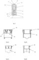
- Figure 2 illustrates several alternative forms of expansion anchors, in which an abutment means is arranged on the anchor rod and shaped to enable torque to be applied thereto, for example, hexagonal head or countersunk head, for different applications.
- any types of abutment to thread rod used for applying torque could be used herein, not limited by the choice of special terminology or term.
- Individual features, method or function related thereto, or combinations thereof may be patentably inventive.
- An expanding member 6 of conically tapering configuration is provided with an inner bore which is internally screw threaded so that the screw thread of the leading portion 11 of the bolt 1 can mesh therewith. It will be clear that as the bolt is rotated the expander member 6 will be drawn deeper into the expansible sleeve 5 from the leading end 11 in the direction towards the trailing end 12. This results in radial expansion of the expansible sleeve 5 into engagement with the surrounding material of the wall in which the bore hole is formed wherein the expansible sleeve 5 is disposed. To facilitate this radial expansion, the expansible sleeve 5 may be provided with longitudinal slots 7 distributed over its circumference.
- FIGS 2a and 2b show the collar 4 according to the present invention.
- the collar 4 is designed as a ring-like body consisting of at least two suitable materials is sandwiched in between the spacer sleeve 3 and the expansible sleeve 5 and is axially compressed.
- the materials which are also non-corrosive to form the collar 4 shall include one first tough and breakproof material, for example, POM resin, ABS, PA, PC, however, at the same time a second relatively soft, deformable material, such as an elastic plastics material, TPE, or rubber.
- the relative dimensions of the collar 4 in relation to the diameter of the threaded rod 1 are believed to be particularly advantageous.
- the annular collar 4 between the spacer sleeve 2 and the expansible sleeve 3 has the same external diameter as the two sleeves 2 and 3.
- the collar 4 is designed as a ring like body. As shown in fig.2a and fig.2b , the ring -like body of the collar 4 include an inner part 41 formed by a first hard material and the outer part 42 formed by a second soft material form.
- the tensile strength of the first material is from 40Mpa to 100Mpa, and the shoreA hardness of the second material as from 40 to 120.
- the tensile strength of the first material is from 60 Mpa to 70Mpa and the shoreA hardness of the second material is from 70 to 90.
- the first material and second material are molded together by double shot molding, the first material molded into the inner part 41 as a stepped ring and the second material molded as ribs or projections 43 on the outer surface of the inner part 41.
- the outer diameter of upper stepped portion is a bit smaller than the outer diameter of the lower step portion of the inner part 41.
- the inner part 41 of the collar 4 could be a ring with higher hardness while the outer part 42 could be multiple rib or projections 43 over the circumferential outer surface of the inner part 41 with ring shape.
- the projects 43 could be designed as a wedge shape as shown in fig.2a .
- the outer part 42 could be designed as ring with some ribs or protections 43, too.
- the projections 43 could be designed with a triangular shape. This could have more balance between the setting energy and anti-spinning, in the lower part has small outer diameter and less contact face to gain easy setting ability, with continuously increasing outer diameter and contact face, at the end we still get anti-spinning function.
- the outer parts could be designed as ribs 44 axial extending along the ring-like inner part 41, which has most contact face to have most stable anti-spinning function.
- the outer part 42 could be with spiral shape.
- the spiral shape of outer part need less setting energy and more contact face comparing with the outer parts as ribs or projections.
- the inner diameter of outer ring substantially equaling to the outer diameter of inner ring body, and the outer ring body assembled to the inner part 41 by press fit or by adhesive.
- the expansion anchor 10 is turned in its stage as extending into the prepared borehole 20, then the conical expanding member 6 is drawn into the expansible sleeve 5.
- the expansible sleeve 5 acts against the cylindrical surface of the receiving borehole 20 to retain the expansion anchor 10 in the concrete.
- Turning of the expansion anchor 10 with the aid of the screwdriver may then be continued until reaching a firm seating of the expansion anchor 10 inside the borehole 20. This firm seating is reached when the conical expanding member 6, as far as is permitted by the diameter of the borehole 20, has been drawn into the expansible sleeve 5.
- the segments 9 of the expansible sleeve 3 are then firmly applied with a majority of their external surface by the conical expanding member 6, to the wall of the borehole 20.
- the object 30 to be secured to a concrete, for example a wall, a ceiling, or a floor is still loosely slipped on to the rod 1 or else, in the position of the expansion anchor as firmly seated in the borehole 20.
- the soft outer part 42 may contact the cylindrical surface of the borehole 20, the projects 43 act against on the inner surface of the borehole, as the material of the outer part is elastic or ductile, the friction between the collar 4 and inner surface of borehole 2 would be increased, therefore, it can prevent spinning of the expansion anchor.
- the expansion anchor is prevented from tilting around the point of firm seating (conical expansion member 5 and segments 9 of the expansible sleeve 3) inside the borehole 20, which otherwise might cause the firm seating inside the borehole 20 to become loose in the long run.
- the collar 4 might deform, even collapse, in its axial length after overcoming an initial deformation force.
- the torque continuing to act on the head 8 upon the initial deformation force being exceeded, the inner part 41 of the collar 4 is broken, so that the collar may be shorten in the axial direction.
- further tightening the expansion anchor 10 yields the axial compression of collar 4 so that the rod is tensioned with no or minimize movement of the anchor toward the head, thereby minimizing the damage to the concrete.
- the inner part 41 of the collar is a stepped ring like body, as shown in the section view of Fig. 4 .
- the inner part 41 consists of individual diameter regions or sections 43 and 44.
- the upper section 43 is smaller than the lower section 44, and the outer part 42 is covered or surrounded around the upper section 43.
- the outer diameter of the outer part could be a bit larger the outer diameter of the lower section 44 of the inner part 41.
- the outer part could be molded by double shot molding directly on the inner part, therefore the collar made by two materials as one piece. It would be advantageously in manufacturing.
- the inner part 41 and the outer part could be individually and connected by an adhesive connection or by being a press fit.
- the function of the collar 4 is to provide sufficient resistance to compression to substantially maintain its axial length, and restrain the anchor from rotation, during initial spreading of the expansible sleeve until the expansible sleeve are thrust against the cylindrical surface of the hole; and thereafter to yield if need be as the compressive forces are increased due to the threaded rod being tensioned.
- a variety of other forms of collar and collar-like structures may be possibly employed in lieu of the collar 4.
- a collar 4 comprising a inner part 41 of perforate metal or hard plastics formed to substantially cylindrical form, or an outer part of softer or more flexible metal or plastic over the inner part 41.
Landscapes
- Engineering & Computer Science (AREA)
- General Engineering & Computer Science (AREA)
- Mechanical Engineering (AREA)
- Dowels (AREA)
- Architecture (AREA)
- Physics & Mathematics (AREA)
- Electromagnetism (AREA)
- Civil Engineering (AREA)
- Structural Engineering (AREA)
- Joining Of Building Structures In Genera (AREA)
Claims (9)
- Ancrage à expansion, comprenant :un boulon (1), un manchon d'espacement (3), un manchon expansible (5), un élément de dilatation (6), etun collier (4), étant agencé entre le manchon expansible (5) et le manchon d'espacement (3) et ayant la forme d'un corps de type anneau,le boulon (1) s'insérant successivement dans le manchon d'espacement (3), le collier (4) et le manchon expansible (5), et raccordé par filetage à l'élément de dilatation (6) au niveau de son extrémité avant, pour de ce fait attirer l'élément de dilatation (6) dans le manchon expansible (5) et le dilater dans le sens radial ;caractérisé en ce que ledit collier (4) est formé d'un premier matériau et d'un second matériau de dureté différente, dans lequel le premier matériau est un matériau résistant et incassable et la résistance à la traction du premier matériau est de 40 MPa à 100 MPa, le second matériau est un matériau souple et déformable et la dureté shore A du second matériau est de 40 à 120, et, dans lequel le premier matériau forme la partie interne du collier (4) et le second matériau forme la partie externe du collier (4).
- Ancrage à expansion selon la revendication 1, dans lequel la dureté du premier matériau est supérieure à la dureté du second matériau.
- Ancrage à expansion selon la revendication 2, dans lequel la partie interne (41) du collier (4) est un corps de type anneau et la partie externe (42) forme un entourage autour de la partie interne (41).
- Ancrage à expansion selon la revendication 2, dans lequel la partie interne (41) et la partie externe (42) sont moulées ensemble par moulage par injection double.
- Ancrage à expansion selon la revendication 2, dans lequel la partie interne (41) et la partie externe (42) sont assemblées par ajustement serré ou adhésif.
- Ancrage à expansion selon l'une quelconque des revendications 1 à 5, dans lequel la partie externe (42) présente des parties saillantes en forme de coin agencées sur la surface externe de la partie interne (41).
- Ancrage à expansion selon l'une quelconque des revendications 1 à 5, dans lequel la partie externe (42) présente des parties saillantes de forme triangulaire agencées sur la surface externe de la partie interne (41).
- Ancrage à expansion selon l'une quelconque des revendications 1 à 5, dans lequel la partie externe (42) présente des nervures s'étendant axialement sur la surface externe de la partie interne (41).
- Ancrage à expansion selon l'une quelconque des revendications 1 à 5, dans lequel le premier matériau est du POM, du PVC ou de l'ABS, et le second matériau est du TPE, du TPU ou du caoutchouc.
Applications Claiming Priority (2)
| Application Number | Priority Date | Filing Date | Title |
|---|---|---|---|
| CN201910864034.8A CN112483524B (zh) | 2019-09-12 | 2019-09-12 | 膨胀型锚栓 |
| PCT/EP2020/074625 WO2021047995A1 (fr) | 2019-09-12 | 2020-09-03 | Cheville à expansion |
Publications (3)
| Publication Number | Publication Date |
|---|---|
| EP4028671A1 EP4028671A1 (fr) | 2022-07-20 |
| EP4028671C0 EP4028671C0 (fr) | 2024-08-14 |
| EP4028671B1 true EP4028671B1 (fr) | 2024-08-14 |
Family
ID=72473523
Family Applications (1)
| Application Number | Title | Priority Date | Filing Date |
|---|---|---|---|
| EP20771486.6A Active EP4028671B1 (fr) | 2019-09-12 | 2020-09-03 | Cheville à expansion |
Country Status (9)
| Country | Link |
|---|---|
| US (1) | US12012985B2 (fr) |
| EP (1) | EP4028671B1 (fr) |
| JP (1) | JP7449370B2 (fr) |
| KR (1) | KR102911515B1 (fr) |
| CN (1) | CN112483524B (fr) |
| AU (1) | AU2020344114B2 (fr) |
| CA (1) | CA3148397A1 (fr) |
| MX (1) | MX2022003083A (fr) |
| WO (1) | WO2021047995A1 (fr) |
Families Citing this family (1)
| Publication number | Priority date | Publication date | Assignee | Title |
|---|---|---|---|---|
| CN114635732B (zh) * | 2022-05-23 | 2022-08-02 | 中铁九局集团第六工程有限公司 | 一种膨胀型抗震支护锚杆及其施工方法 |
Citations (1)
| Publication number | Priority date | Publication date | Assignee | Title |
|---|---|---|---|---|
| GB1558904A (en) * | 1976-08-17 | 1980-01-09 | Hilti Ag | Expansible dowel |
Family Cites Families (19)
| Publication number | Priority date | Publication date | Assignee | Title |
|---|---|---|---|---|
| US3283640A (en) * | 1964-06-20 | 1966-11-08 | Ono Teizo | Anchor bolt |
| DE2458317B2 (de) | 1974-12-10 | 1979-04-05 | Heinrich 6102 Pfungstadt Liebig | Spreizdübel |
| DE2536136A1 (de) * | 1975-08-13 | 1977-03-03 | Hilti Ag | Spreizduebel |
| US4403734A (en) | 1980-02-07 | 1983-09-13 | Lyncross Pty, Ltd. | Expanding-sleeve rail fastening |
| DE3110485A1 (de) | 1981-03-18 | 1982-09-30 | Phillips Drill Co GmbH, 6971 Hütschenhausen | Spreizanker |
| DE3420375C2 (de) | 1984-06-01 | 1987-03-19 | Fischer, Artur, Dr.H.C., 7244 Waldachtal | Dübel |
| GB8606440D0 (en) | 1986-03-15 | 1986-04-23 | Johnson Metal Press Workers Lt | Fastening device |
| DE3707510A1 (de) * | 1987-02-21 | 1988-09-01 | Fischer Artur Werke Gmbh | Duebel mit spreizhuelse |
| JPH04140506A (ja) | 1990-09-28 | 1992-05-14 | Japan Drive-It Co Ltd | 拡開アンカ |
| DE10035580B4 (de) * | 2000-07-21 | 2013-07-25 | Simpson Strong-Tie Ireland Limited | Formschlüssig setzbarer Hinterschneid-Anker |
| CA2498085A1 (fr) * | 2004-02-23 | 2005-08-23 | Knape & Vogt Manufacturing Company | Plateau pivotant avec installation sans outils |
| CN101305161B (zh) * | 2005-11-09 | 2011-06-15 | 山特维克知识产权股份有限公司 | 自钻岩锚杆 |
| DE102006031467A1 (de) | 2006-07-07 | 2008-01-10 | Fischerwerke Artur Fischer Gmbh & Co. Kg | Spreizanker |
| DE102006039195A1 (de) * | 2006-08-22 | 2008-03-13 | Ccg-Concept Consulting Gmbh | Bolzenanker mit Spreizhülse |
| WO2008022630A1 (fr) * | 2006-08-22 | 2008-02-28 | Ccg-Concept Consulting Gmbh | Tirant d'ancrage |
| JP5682742B2 (ja) * | 2009-05-08 | 2015-03-11 | 東芝ライテック株式会社 | 電源装置及び照明装置 |
| CN204591910U (zh) * | 2015-04-29 | 2015-08-26 | 上海翔锐紧固件有限公司 | 一种新款重型锚栓 |
| CN208057631U (zh) * | 2017-12-12 | 2018-11-06 | 苏州茂隆电梯配件有限公司 | 一种隔震锚栓 |
| JP2022024949A (ja) * | 2020-07-28 | 2022-02-09 | 真実 大西 | 耳掻き付ボールペンキャップ |
-
2019
- 2019-09-12 CN CN201910864034.8A patent/CN112483524B/zh active Active
-
2020
- 2020-09-03 EP EP20771486.6A patent/EP4028671B1/fr active Active
- 2020-09-03 US US17/641,344 patent/US12012985B2/en active Active
- 2020-09-03 CA CA3148397A patent/CA3148397A1/fr active Pending
- 2020-09-03 KR KR1020227007282A patent/KR102911515B1/ko active Active
- 2020-09-03 JP JP2022516065A patent/JP7449370B2/ja active Active
- 2020-09-03 WO PCT/EP2020/074625 patent/WO2021047995A1/fr not_active Ceased
- 2020-09-03 AU AU2020344114A patent/AU2020344114B2/en active Active
- 2020-09-03 MX MX2022003083A patent/MX2022003083A/es unknown
Patent Citations (1)
| Publication number | Priority date | Publication date | Assignee | Title |
|---|---|---|---|---|
| GB1558904A (en) * | 1976-08-17 | 1980-01-09 | Hilti Ag | Expansible dowel |
Also Published As
| Publication number | Publication date |
|---|---|
| EP4028671C0 (fr) | 2024-08-14 |
| EP4028671A1 (fr) | 2022-07-20 |
| AU2020344114A1 (en) | 2022-02-17 |
| WO2021047995A1 (fr) | 2021-03-18 |
| KR20220054805A (ko) | 2022-05-03 |
| CN112483524B (zh) | 2022-12-16 |
| JP7449370B2 (ja) | 2024-03-13 |
| US20220341452A1 (en) | 2022-10-27 |
| CN112483524A (zh) | 2021-03-12 |
| CA3148397A1 (fr) | 2021-03-18 |
| US12012985B2 (en) | 2024-06-18 |
| JP2023501047A (ja) | 2023-01-18 |
| AU2020344114B2 (en) | 2025-06-26 |
| MX2022003083A (es) | 2022-04-11 |
| KR102911515B1 (ko) | 2026-01-12 |
Similar Documents
| Publication | Publication Date | Title |
|---|---|---|
| US5993129A (en) | Bolt anchoring device with improved plug portion of bolt | |
| US6273655B1 (en) | Anchoring device | |
| JP4295349B2 (ja) | 膨張アンカーおよびその設置方法 | |
| US4287807A (en) | Pull-to-set anchoring device | |
| US6450745B2 (en) | Dowel with a weakened section adjoining the leading threaded end thereof | |
| US4330230A (en) | Anchor bolt assembly | |
| US20020106256A1 (en) | Expandable anchorage | |
| GB2027153A (en) | Anchor bolt assembly | |
| EP4028671B1 (fr) | Cheville à expansion | |
| US4537541A (en) | Anchor bolt assembly | |
| US4940372A (en) | Anchoring plug | |
| HK40068996B (en) | Expansion anchor | |
| HK40068996A (en) | Expansion anchor | |
| JP2020020372A (ja) | ブラインドボルト | |
| GB2190164A (en) | Anchoring device | |
| WO2009127865A1 (fr) | Fixation | |
| KR19980032552A (ko) | 볼트 고정 장치 | |
| US20240369090A1 (en) | Anchor bolt | |
| US6241443B1 (en) | Fastener with staged locking system | |
| EP3622185B1 (fr) | Dispositif de fixation |
Legal Events
| Date | Code | Title | Description |
|---|---|---|---|
| STAA | Information on the status of an ep patent application or granted ep patent |
Free format text: STATUS: UNKNOWN |
|
| STAA | Information on the status of an ep patent application or granted ep patent |
Free format text: STATUS: THE INTERNATIONAL PUBLICATION HAS BEEN MADE |
|
| PUAI | Public reference made under article 153(3) epc to a published international application that has entered the european phase |
Free format text: ORIGINAL CODE: 0009012 |
|
| STAA | Information on the status of an ep patent application or granted ep patent |
Free format text: STATUS: REQUEST FOR EXAMINATION WAS MADE |
|
| 17P | Request for examination filed |
Effective date: 20220412 |
|
| AK | Designated contracting states |
Kind code of ref document: A1 Designated state(s): AL AT BE BG CH CY CZ DE DK EE ES FI FR GB GR HR HU IE IS IT LI LT LU LV MC MK MT NL NO PL PT RO RS SE SI SK SM TR |
|
| REG | Reference to a national code |
Ref country code: HK Ref legal event code: DE Ref document number: 40068996 Country of ref document: HK |
|
| DAV | Request for validation of the european patent (deleted) | ||
| DAX | Request for extension of the european patent (deleted) | ||
| STAA | Information on the status of an ep patent application or granted ep patent |
Free format text: STATUS: EXAMINATION IS IN PROGRESS |
|
| 17Q | First examination report despatched |
Effective date: 20230504 |
|
| GRAP | Despatch of communication of intention to grant a patent |
Free format text: ORIGINAL CODE: EPIDOSNIGR1 |
|
| STAA | Information on the status of an ep patent application or granted ep patent |
Free format text: STATUS: GRANT OF PATENT IS INTENDED |
|
| INTG | Intention to grant announced |
Effective date: 20240531 |
|
| GRAS | Grant fee paid |
Free format text: ORIGINAL CODE: EPIDOSNIGR3 |
|
| GRAA | (expected) grant |
Free format text: ORIGINAL CODE: 0009210 |
|
| STAA | Information on the status of an ep patent application or granted ep patent |
Free format text: STATUS: THE PATENT HAS BEEN GRANTED |
|
| AK | Designated contracting states |
Kind code of ref document: B1 Designated state(s): AL AT BE BG CH CY CZ DE DK EE ES FI FR GB GR HR HU IE IS IT LI LT LU LV MC MK MT NL NO PL PT RO RS SE SI SK SM TR |
|
| REG | Reference to a national code |
Ref country code: GB Ref legal event code: FG4D |
|
| REG | Reference to a national code |
Ref country code: CH Ref legal event code: EP |
|
| REG | Reference to a national code |
Ref country code: DE Ref legal event code: R096 Ref document number: 602020035823 Country of ref document: DE |
|
| REG | Reference to a national code |
Ref country code: IE Ref legal event code: FG4D |
|
| U01 | Request for unitary effect filed |
Effective date: 20240814 |
|
| U07 | Unitary effect registered |
Designated state(s): AT BE BG DE DK EE FI FR IT LT LU LV MT NL PT SE SI Effective date: 20240827 |
|
| U20 | Renewal fee for the european patent with unitary effect paid |
Year of fee payment: 5 Effective date: 20241025 |
|
| PG25 | Lapsed in a contracting state [announced via postgrant information from national office to epo] |
Ref country code: NO Free format text: LAPSE BECAUSE OF FAILURE TO SUBMIT A TRANSLATION OF THE DESCRIPTION OR TO PAY THE FEE WITHIN THE PRESCRIBED TIME-LIMIT Effective date: 20241114 |
|
| PG25 | Lapsed in a contracting state [announced via postgrant information from national office to epo] |
Ref country code: PL Free format text: LAPSE BECAUSE OF FAILURE TO SUBMIT A TRANSLATION OF THE DESCRIPTION OR TO PAY THE FEE WITHIN THE PRESCRIBED TIME-LIMIT Effective date: 20240814 Ref country code: GR Free format text: LAPSE BECAUSE OF FAILURE TO SUBMIT A TRANSLATION OF THE DESCRIPTION OR TO PAY THE FEE WITHIN THE PRESCRIBED TIME-LIMIT Effective date: 20241115 |
|
| PG25 | Lapsed in a contracting state [announced via postgrant information from national office to epo] |
Ref country code: IS Free format text: LAPSE BECAUSE OF FAILURE TO SUBMIT A TRANSLATION OF THE DESCRIPTION OR TO PAY THE FEE WITHIN THE PRESCRIBED TIME-LIMIT Effective date: 20241214 |
|
| PG25 | Lapsed in a contracting state [announced via postgrant information from national office to epo] |
Ref country code: HR Free format text: LAPSE BECAUSE OF FAILURE TO SUBMIT A TRANSLATION OF THE DESCRIPTION OR TO PAY THE FEE WITHIN THE PRESCRIBED TIME-LIMIT Effective date: 20240814 |
|
| PG25 | Lapsed in a contracting state [announced via postgrant information from national office to epo] |
Ref country code: RS Free format text: LAPSE BECAUSE OF FAILURE TO SUBMIT A TRANSLATION OF THE DESCRIPTION OR TO PAY THE FEE WITHIN THE PRESCRIBED TIME-LIMIT Effective date: 20241114 Ref country code: ES Free format text: LAPSE BECAUSE OF FAILURE TO SUBMIT A TRANSLATION OF THE DESCRIPTION OR TO PAY THE FEE WITHIN THE PRESCRIBED TIME-LIMIT Effective date: 20240814 |
|
| PG25 | Lapsed in a contracting state [announced via postgrant information from national office to epo] |
Ref country code: RS Free format text: LAPSE BECAUSE OF FAILURE TO SUBMIT A TRANSLATION OF THE DESCRIPTION OR TO PAY THE FEE WITHIN THE PRESCRIBED TIME-LIMIT Effective date: 20241114 Ref country code: PL Free format text: LAPSE BECAUSE OF FAILURE TO SUBMIT A TRANSLATION OF THE DESCRIPTION OR TO PAY THE FEE WITHIN THE PRESCRIBED TIME-LIMIT Effective date: 20240814 Ref country code: NO Free format text: LAPSE BECAUSE OF FAILURE TO SUBMIT A TRANSLATION OF THE DESCRIPTION OR TO PAY THE FEE WITHIN THE PRESCRIBED TIME-LIMIT Effective date: 20241114 Ref country code: IS Free format text: LAPSE BECAUSE OF FAILURE TO SUBMIT A TRANSLATION OF THE DESCRIPTION OR TO PAY THE FEE WITHIN THE PRESCRIBED TIME-LIMIT Effective date: 20241214 Ref country code: HR Free format text: LAPSE BECAUSE OF FAILURE TO SUBMIT A TRANSLATION OF THE DESCRIPTION OR TO PAY THE FEE WITHIN THE PRESCRIBED TIME-LIMIT Effective date: 20240814 Ref country code: GR Free format text: LAPSE BECAUSE OF FAILURE TO SUBMIT A TRANSLATION OF THE DESCRIPTION OR TO PAY THE FEE WITHIN THE PRESCRIBED TIME-LIMIT Effective date: 20241115 Ref country code: ES Free format text: LAPSE BECAUSE OF FAILURE TO SUBMIT A TRANSLATION OF THE DESCRIPTION OR TO PAY THE FEE WITHIN THE PRESCRIBED TIME-LIMIT Effective date: 20240814 |
|
| PG25 | Lapsed in a contracting state [announced via postgrant information from national office to epo] |
Ref country code: SM Free format text: LAPSE BECAUSE OF FAILURE TO SUBMIT A TRANSLATION OF THE DESCRIPTION OR TO PAY THE FEE WITHIN THE PRESCRIBED TIME-LIMIT Effective date: 20240814 |
|
| PG25 | Lapsed in a contracting state [announced via postgrant information from national office to epo] |
Ref country code: CZ Free format text: LAPSE BECAUSE OF FAILURE TO SUBMIT A TRANSLATION OF THE DESCRIPTION OR TO PAY THE FEE WITHIN THE PRESCRIBED TIME-LIMIT Effective date: 20240814 |
|
| PG25 | Lapsed in a contracting state [announced via postgrant information from national office to epo] |
Ref country code: SK Free format text: LAPSE BECAUSE OF FAILURE TO SUBMIT A TRANSLATION OF THE DESCRIPTION OR TO PAY THE FEE WITHIN THE PRESCRIBED TIME-LIMIT Effective date: 20240814 |
|
| PLBE | No opposition filed within time limit |
Free format text: ORIGINAL CODE: 0009261 |
|
| STAA | Information on the status of an ep patent application or granted ep patent |
Free format text: STATUS: NO OPPOSITION FILED WITHIN TIME LIMIT |
|
| PG25 | Lapsed in a contracting state [announced via postgrant information from national office to epo] |
Ref country code: MC Free format text: LAPSE BECAUSE OF FAILURE TO SUBMIT A TRANSLATION OF THE DESCRIPTION OR TO PAY THE FEE WITHIN THE PRESCRIBED TIME-LIMIT Effective date: 20240814 |
|
| 26N | No opposition filed |
Effective date: 20250515 |
|
| PG25 | Lapsed in a contracting state [announced via postgrant information from national office to epo] |
Ref country code: IE Free format text: LAPSE BECAUSE OF NON-PAYMENT OF DUE FEES Effective date: 20240903 |
|
| REG | Reference to a national code |
Ref country code: CH Ref legal event code: U11 Free format text: ST27 STATUS EVENT CODE: U-0-0-U10-U11 (AS PROVIDED BY THE NATIONAL OFFICE) Effective date: 20251001 |
|
| PGFP | Annual fee paid to national office [announced via postgrant information from national office to epo] |
Ref country code: GB Payment date: 20250919 Year of fee payment: 6 |
|
| U20 | Renewal fee for the european patent with unitary effect paid |
Year of fee payment: 6 Effective date: 20250924 |
|
| PG25 | Lapsed in a contracting state [announced via postgrant information from national office to epo] |
Ref country code: RO Free format text: LAPSE BECAUSE OF FAILURE TO SUBMIT A TRANSLATION OF THE DESCRIPTION OR TO PAY THE FEE WITHIN THE PRESCRIBED TIME-LIMIT Effective date: 20240814 |
|
| PGFP | Annual fee paid to national office [announced via postgrant information from national office to epo] |
Ref country code: CH Payment date: 20251001 Year of fee payment: 6 |
|
| PG25 | Lapsed in a contracting state [announced via postgrant information from national office to epo] |
Ref country code: CY Free format text: LAPSE BECAUSE OF FAILURE TO SUBMIT A TRANSLATION OF THE DESCRIPTION OR TO PAY THE FEE WITHIN THE PRESCRIBED TIME-LIMIT; INVALID AB INITIO Effective date: 20200903 |
|
| PG25 | Lapsed in a contracting state [announced via postgrant information from national office to epo] |
Ref country code: HU Free format text: LAPSE BECAUSE OF FAILURE TO SUBMIT A TRANSLATION OF THE DESCRIPTION OR TO PAY THE FEE WITHIN THE PRESCRIBED TIME-LIMIT; INVALID AB INITIO Effective date: 20200903 |