EP4029151B1 - Procédé et appareil pour la rétroaction d'information d'état de canal pour la transmission conjointe - Google Patents
Procédé et appareil pour la rétroaction d'information d'état de canal pour la transmission conjointe Download PDFInfo
- Publication number
- EP4029151B1 EP4029151B1 EP20885220.2A EP20885220A EP4029151B1 EP 4029151 B1 EP4029151 B1 EP 4029151B1 EP 20885220 A EP20885220 A EP 20885220A EP 4029151 B1 EP4029151 B1 EP 4029151B1
- Authority
- EP
- European Patent Office
- Prior art keywords
- matrix
- aggregated
- aps
- channel
- csi
- Prior art date
- Legal status (The legal status is an assumption and is not a legal conclusion. Google has not performed a legal analysis and makes no representation as to the accuracy of the status listed.)
- Active
Links
Images




Classifications
-
- H—ELECTRICITY
- H04—ELECTRIC COMMUNICATION TECHNIQUE
- H04B—TRANSMISSION
- H04B7/00—Radio transmission systems, i.e. using radiation field
- H04B7/02—Diversity systems; Multi-antenna system, i.e. transmission or reception using multiple antennas
- H04B7/04—Diversity systems; Multi-antenna system, i.e. transmission or reception using multiple antennas using two or more spaced independent antennas
- H04B7/06—Diversity systems; Multi-antenna system, i.e. transmission or reception using multiple antennas using two or more spaced independent antennas at the transmitting station
- H04B7/0613—Diversity systems; Multi-antenna system, i.e. transmission or reception using multiple antennas using two or more spaced independent antennas at the transmitting station using simultaneous transmission
- H04B7/0615—Diversity systems; Multi-antenna system, i.e. transmission or reception using multiple antennas using two or more spaced independent antennas at the transmitting station using simultaneous transmission of weighted versions of same signal
- H04B7/0619—Diversity systems; Multi-antenna system, i.e. transmission or reception using multiple antennas using two or more spaced independent antennas at the transmitting station using simultaneous transmission of weighted versions of same signal using feedback from receiving side
- H04B7/0621—Feedback content
- H04B7/0626—Channel coefficients, e.g. channel state information [CSI]
-
- H—ELECTRICITY
- H04—ELECTRIC COMMUNICATION TECHNIQUE
- H04B—TRANSMISSION
- H04B7/00—Radio transmission systems, i.e. using radiation field
- H04B7/02—Diversity systems; Multi-antenna system, i.e. transmission or reception using multiple antennas
- H04B7/022—Site diversity; Macro-diversity
- H04B7/024—Co-operative use of antennas of several sites, e.g. in co-ordinated multipoint or co-operative multiple-input multiple-output [MIMO] systems
-
- H—ELECTRICITY
- H04—ELECTRIC COMMUNICATION TECHNIQUE
- H04B—TRANSMISSION
- H04B7/00—Radio transmission systems, i.e. using radiation field
- H04B7/02—Diversity systems; Multi-antenna system, i.e. transmission or reception using multiple antennas
- H04B7/04—Diversity systems; Multi-antenna system, i.e. transmission or reception using multiple antennas using two or more spaced independent antennas
- H04B7/0413—MIMO systems
- H04B7/0417—Feedback systems
-
- H—ELECTRICITY
- H04—ELECTRIC COMMUNICATION TECHNIQUE
- H04B—TRANSMISSION
- H04B7/00—Radio transmission systems, i.e. using radiation field
- H04B7/02—Diversity systems; Multi-antenna system, i.e. transmission or reception using multiple antennas
- H04B7/04—Diversity systems; Multi-antenna system, i.e. transmission or reception using multiple antennas using two or more spaced independent antennas
- H04B7/0413—MIMO systems
- H04B7/0456—Selection of precoding matrices or codebooks, e.g. using matrices antenna weighting
-
- H—ELECTRICITY
- H04—ELECTRIC COMMUNICATION TECHNIQUE
- H04B—TRANSMISSION
- H04B7/00—Radio transmission systems, i.e. using radiation field
- H04B7/02—Diversity systems; Multi-antenna system, i.e. transmission or reception using multiple antennas
- H04B7/04—Diversity systems; Multi-antenna system, i.e. transmission or reception using multiple antennas using two or more spaced independent antennas
- H04B7/06—Diversity systems; Multi-antenna system, i.e. transmission or reception using multiple antennas using two or more spaced independent antennas at the transmitting station
- H04B7/0613—Diversity systems; Multi-antenna system, i.e. transmission or reception using multiple antennas using two or more spaced independent antennas at the transmitting station using simultaneous transmission
- H04B7/0615—Diversity systems; Multi-antenna system, i.e. transmission or reception using multiple antennas using two or more spaced independent antennas at the transmitting station using simultaneous transmission of weighted versions of same signal
- H04B7/0617—Diversity systems; Multi-antenna system, i.e. transmission or reception using multiple antennas using two or more spaced independent antennas at the transmitting station using simultaneous transmission of weighted versions of same signal for beam forming
-
- H—ELECTRICITY
- H04—ELECTRIC COMMUNICATION TECHNIQUE
- H04L—TRANSMISSION OF DIGITAL INFORMATION, e.g. TELEGRAPHIC COMMUNICATION
- H04L25/00—Baseband systems
- H04L25/02—Details ; arrangements for supplying electrical power along data transmission lines
- H04L25/0202—Channel estimation
- H04L25/0204—Channel estimation of multiple channels
-
- H—ELECTRICITY
- H04—ELECTRIC COMMUNICATION TECHNIQUE
- H04L—TRANSMISSION OF DIGITAL INFORMATION, e.g. TELEGRAPHIC COMMUNICATION
- H04L25/00—Baseband systems
- H04L25/02—Details ; arrangements for supplying electrical power along data transmission lines
- H04L25/0202—Channel estimation
- H04L25/0224—Channel estimation using sounding signals
-
- H—ELECTRICITY
- H04—ELECTRIC COMMUNICATION TECHNIQUE
- H04L—TRANSMISSION OF DIGITAL INFORMATION, e.g. TELEGRAPHIC COMMUNICATION
- H04L25/00—Baseband systems
- H04L25/02—Details ; arrangements for supplying electrical power along data transmission lines
- H04L25/0202—Channel estimation
- H04L25/024—Channel estimation channel estimation algorithms
- H04L25/0242—Channel estimation channel estimation algorithms using matrix methods
- H04L25/0248—Eigen-space methods
-
- H—ELECTRICITY
- H04—ELECTRIC COMMUNICATION TECHNIQUE
- H04W—WIRELESS COMMUNICATION NETWORKS
- H04W84/00—Network topologies
- H04W84/02—Hierarchically pre-organised networks, e.g. paging networks, cellular networks, WLAN [Wireless Local Area Network] or WLL [Wireless Local Loop]
- H04W84/10—Small scale networks; Flat hierarchical networks
- H04W84/12—WLAN [Wireless Local Area Networks]
-
- H—ELECTRICITY
- H04—ELECTRIC COMMUNICATION TECHNIQUE
- H04W—WIRELESS COMMUNICATION NETWORKS
- H04W24/00—Supervisory, monitoring or testing arrangements
- H04W24/10—Scheduling measurement reports ; Arrangements for measurement reports
Definitions
- the present invention relates generally to the field of wireless communication systems, and in particular, to sounding protocols when using access point (AP) collaboration.
- AP access point
- Wireless local area network (WLAN) communication systems such as the IEEE ® 802.11 family of WiFi protocols, include wireless communication devices that transmit and receive signals, including access points (APs), that function as an interface between the WLAN and one or more further networks, and stations (STA) that are devices that support the 802.11 protocol and exchange signals with the APs.
- APs access points
- STA stations
- Both APs and STAs may incorporate multiple-input multiple-output (MIMO) technology where the wireless communication devices has multiple antenna. This allows techniques such as beamforming to be used to increase the performance and throughput of the wireless network.
- MIMO multiple-input multiple-output
- An AP uses sounding protocols to estimate the characteristics of the communication channel between antennas on the AP and antennas on STAs. Sounding packets are sent from the AP to the STA. The STA analyzes and evaluates the reception of the sounding packets, and information is fed back to the sending AP. The AP then utilizes this 'channel state information' (CSI) in configuring its transmissions to the STA.
- CSI channel state information'
- a plurality of APs may work in collaboration to communicate with one or more STAs in a WLAN.
- the proposed IEEE 802.11be standard is being developed to support a next generation of Extremely High Throughput (EHT) WLAN.
- EHT communication may be achieved with AP collaboration, which can utilize coordination between multiple APs, and multiple antennas on APs, to minimize interference and improve quality of service for communications with STAs.
- a plurality of APs may work in collaboration to communicate with one or more STAs to achieve increased or improved throughput.
- AP collaboration may also serve to minimize interference and improve quality of service for communications with STAs.
- US 2012/106384 describes an apparatus and a system for transmitting channel state information, which acquires channel state information of a channel between a mobile terminal and two or more cooperative base stations.
- An object of embodiments of the present invention is to provide a method and apparatus for sounding protocols when using AP collaboration.
- the scope of the present invention is set out by the appended claims.
- a method for determining channel state information (CSI) of a wireless channel by a station includes receiving a plurality of sounding data transmissions from a plurality of access points (APs) over a plurality of communication channels. Estimating, for each of the plurality of communication channels, a CSI of the channel based on the plurality of sounding data transmissions.
- APs access points
- the plurality of sounding data transmissions are received serially.
- the plurality of sounding data transmissions are received concurrently.
- the aggregated matrix includes a measured gain and a measured phase of the plurality of sounding data transmissions.
- the plurality of communication channels use an 802.11 WiFi protocol.
- the 802.11 protocol includes multiple-input multiple-output (MIMO) protocols.
- MIMO multiple-input multiple-output
- Any of the above mentioned embodiments further include determining that joint transmission is used by the plurality of APs over the plurality of communication channels.
- the method includes transmitting a sounding data transmission to a plurality of stations (STAs) over a plurality of communication channels.
- STAs stations
- Reconstructing an aggregate matrix of the CSI based on the ⁇ matrix and the V matrix pair received from the plurality of STAs, and computing a precoder matrix based on the aggregate matrix.
- the sounding data transmission is transmitted concurrent with a plurality of sounding data transmissions.
- the sounding data transmission is transmitted in series with a plurality of sounding data transmissions.
- Any of the above mentioned embodiments further include the AP communicating with one of the plurality of STAs using the precoder matrix with coordinated beam forming techniques.
- Any of the above mentioned embodiments further include the AP communicating portions of a plurality of data streams with the plurality of STAs using the precoder matrix with joint transmission techniques.
- a station for communicating over a communications channel.
- the STA includes a processor and a non-transient memory for storing instructions which when executed by the processor cause the STA to perform the following: Receive a plurality of sounding data transmissions from a plurality of access points (APs) over a plurality of communication channels. Estimate, for each of the plurality of communication channels, a CSI of the channel based on the plurality of sounding data transmissions.
- APs access points
- the plurality of sounding data transmissions are received serially.
- the plurality of sounding data transmissions are received concurrently.
- the aggregated matrix includes a measured gain and a measured phase of the plurality of sounding data transmissions.
- the plurality of communication channels use an 802.11 WiFi protocol.
- the 802.11 protocol includes multiple-input multiple-output (MIMO) protocols.
- MIMO multiple-input multiple-output
- Any of the above mentioned embodiments further include determining that joint transmission is used by the plurality of APs over the plurality of communication channels.
- Embodiments have been described above in conjunctions with aspects of the present invention upon which they can be implemented. Those skilled in the art will appreciate that embodiments may be implemented in conjunction with the aspect with which they are described, but may also be implemented with other embodiments of that aspect. When embodiments are mutually exclusive, or are otherwise incompatible with each other, it will be apparent to those skilled in the art. Some embodiments may be described in relation to one aspect, but may also be applicable to other aspects, as will be apparent to those of skill in the art.
- An object of embodiments of the present invention is to provide a method and apparatus for implementing sounding protocols when using access point (AP) collaboration.
- Wireless networks typically include a number of end user stations, referred to as STAs, that are wirelessly connected to access points (APs) that provide access to a wider local-area network (LAN), wide-area network (WAN), the Internet, and any number of other wired and wireless networks as are known in the art.
- STAs end user stations
- APs access points
- LAN local-area network
- WAN wide-area network
- Internet any number of other wired and wireless networks as are known in the art.
- LAN local-area network
- WAN wide-area network
- Internet any number of other wired and wireless networks as are known in the art.
- STAs include any wireless entity such as a cell phone, tablet, laptop computer, another AP, a vehicle, a beacon, and others.
- Some of the most ubiquitous wireless networks are based on the IEEE 802.11 family of standards that define the protocols to be used for wireless communications.
- One of the more recent standards in the family of protocols is the 802.11be Extremely High Throughput (EHT).
- EHT Extremely High Throughput
- One of the features of 802.11be is known as Multi-Access Point (AP) coordination, where a STA can connect to multiple APs in order to optimize the wireless connection for speed, distance, signal to noise ratio (SNR), or other factors. Allowing for a STA to connect to multiple APs, or for an AP to connect to multiple STAs allows for multiple paths that may be used to optimize the connection of the STA, through APs, to the wider network.
- AP Multi-Access Point
- Modern wireless STAs and APs also support multiple-input and multiple output (MIMO) technology, where each STA and AP may transmit and receive using multiple transmitting and receiving antennas.
- MIMO technology in the STA and AP allows them to use multistream transmissions in order to increase throughput, range, or both throughput and range.
- An additional benefit of the multiple antennas of MIMO configurations is that beamforming may be used to control the direction of the wireless transmissions leading to more improvements.
- the path between each antenna on an AP and each antenna on a STA may be optimized independently.
- FIG. 1 is block diagram of a wireless communication device or system 100 that may be used for implementing STAs and APs utilizing the methods disclosed herein. Examples would be a cell phone, portable computer, tablet, wireless access point, etc. Specific devices 100 may utilize all of the components shown or only a subset of the components, and levels of integration may vary from device to device. Furthermore, a device may contain multiple instances of a component, such as multiple processing units, processors, memories, transmitters, receivers, etc. The device 100 includes a processing unit 110.
- the processing unit 110 typically includes a processor, also known as a central processing unit (CPU) 110, a bus and a memory 120, and may optionally also include a mass storage device 130, a video adapter 140, and an I/O interface 160 (each shown in dashed lines to indicate they are optional).
- the device 100 may further include one or more network interface(s) 150 for connecting the device to communication networks 102 which may be wired networks or wireless networks such as IEEE 802.11 compatible wireless networks.
- the device 100 may further include one or more radio access network interface(s) 190 for connecting the computing system to cellular networks 104 which may be cellular networks such as 3G, 4G, LTE, 5G, etc.
- the CPU 110 may comprise any type of electronic data processor, and may include one or more cores or processing elements.
- the memory 120 may comprise any type of non-transitory system memory such as static random access memory (SRAM), dynamic random access memory (DRAM), synchronous DRAM (SDRAM), read-only memory (ROM), or a combination thereof.
- the memory may include ROM for use at boot-up, and DRAM for program and data storage for use while executing programs.
- the bus may be one or more of any type of several bus architectures including a memory bus or memory controller, a peripheral bus, or a video bus.
- the mass storage 130 may comprise any type of non-transitory storage device configured to store data, programs, and other information and to make the data, programs, and other information accessible via the bus.
- the mass storage may comprise, for example, one or more of a solid state drive, hard disk drive, a magnetic disk drive, or an optical disk drive.
- the video adapter 140 and the I/O interface 160 provide optional interfaces to couple external input and output devices to the processing unit.
- input and output devices include a display 170 coupled to the video adapter 140 and an I/O device 180 such as a touch-screen coupled to the I/O interface 1160.
- Other devices may be coupled to the CPU 110, and additional or fewer interfaces may be utilized.
- a serial interface such as Universal Serial Bus (USB) (not shown) may be used to provide an interface for an external device.
- USB Universal Serial Bus
- the computing system may rely upon the network interface(s) for connection to available mass storage(s), video adapter(s), and I/O interface(s) available on the networks.
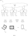
- FIG. 2 illustrates an embodiment 200 of STAs wirelessly connecting to the Internet 202 through APs.
- K 1 , K 2 , ..., K L are data streams to be scheduled. It is understood that in other embodiments, the Internet 202 may be replaced by any other computer network that the STAs are configured to connect to.
- APs 204, 206, 208 are illustrative of a plurality of APs providing wireless network access in an area. In general, there may be L APs, where L is a positive integer.
- Each of the L APs has a MIMO architecture and in particular supports a number; N 1 , N 2 , ..., N L transmit antennas that may support MIMO technology including beamforming.
- Each of the L APs 204, 206, 208 is connected directly or indirectly to the Internet 202.
- Three STAs are illustrated; a laptop computer 210, a tablet 212, and a cell phone 214. Any arbitrary number of STAs may be supported in embodiments 200, only limited by the area of coverage of the APs and the number of STAs that may affect the responsiveness and throughput capacity of the APs that may cause the service to a STA to degrade below acceptable limits.
- STAs connect to one or more APs in order to access the Internet.
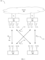
- FIG. 3 illustrates a similar embodiment to FIG. 2 , showing two APs and two STAs for illustrative purposes.
- STA1 304 and STA2 306 access AP1 204 and AP2 206 to gain access to the Internet 202.
- AP1 204 and AP2 206 implement multi-AP coordination that enables the two STAs to connect to one or both APs.
- Multi-AP techniques include techniques known as "coordinated beam forming” (CBF) and "joint transmission” (JT).
- CBF Coordinatd beam forming
- JT joint transmission
- STA1 304 may be scheduled to communicate with AP1 204
- STA2 306 may be scheduled to communicate with AP2 206.
- K 1 and K 2 streams of data are shared between AP1 204 and AP2 206 to communicate jointly with STA1 304 and STA2 306.
- a calibration procedure known as 'sounding' is used to estimate wireless communications Channel State Information (CSI) between antennas on an AP and antennas on a STA.
- the CSI measurements are used to configure beamforming transmissions between the AP and the STA.
- an AP transmits null data packets (NDPs) to STAs.
- NDPs null data packets
- Each STA that receives one or more NDP packets analyzes them to calculate or estimate the channel or channel responses to produce a feedback matrix for combinations of communications between the APs and STAs.
- estimating the channel includes measuring the phase and gain of the received NDP or NDPs.
- each STA When using multi-AP coordination, the calculation of the CSI is performed by each STA. The CSI information from the STAs is then fed back to each AP. Each AP is responsible to aggregate information received from STAs to compute a precoder that may be used when a plurality of APs coordinate to perform a joint transmission (JT) to a STA or to communicate using CBF to scheduled STAs. The precoder is used by MIMO transmitters to determine the transmission parameters to use for each of their transmitting antennas.
- JT joint transmission
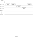
- FIG. 5 illustrates a serial sounding procedure 500 according to an embodiment.
- a master AP sends an NDP Announcement (NDPA) frame towards the STAs to start the procedure.
- the master AP is an AP designated to initiate the sounding procedure.
- the master AP then sends a first NDP frame (shown as NDP1).
- NDP1 NDP 1
- Slave AP 1 sends a second NDP frame NDP2
- another Slave AP 2 sends a third NDP frame NDP3.
- the master AP sends a trigger frame that signals to the STAs to feed back their CSI beamforming report(s).
- serial sounding allows each STA to estimate the channel to each individual AP without influences from other APs.
- FIG. 6 illustrates a first concurrent sounding procedure 600 according to an embodiment.
- a master AP sends an NDPA frame towards the STAs to start the procedure. Then both master and slave APs simultaneously send NDP frames towards the STAs. Next, the master AP sends the trigger frame that signals to the STAs to feed back their CSI beamforming report(s). Additional slave APs may also participate in this sounding procedure, by sending their respective NDP frames concurrently with NDP1 and NDP2.
- FIG. 7 illustrates a second concurrent sounding procedure 700 according to an embodiment.
- a master AP sends a Sounding Trigger frame towards the STAs to start the procedure. Then both master and slave APs simultaneously send NDPA frames towards the STAs. Following this, both master and slave APs simultaneously send NDP frames towards the STAs. Next, the master AP sends the trigger frame that signals to the STAs to feedback their CSI beamforming report(s). Additional slave APs may also participate in this sounding procedure, by sending their respective NDP frames concurrently with NDPA, NDP1 and NDP2.
- the figure illustrates two APs performing multi-AP collaboration with each of two STAs.
- AP1 204 has N 1 Tx antennas.
- AP2 206 has N 2 Tx antennas.
- STA1 304 has M 1 Rx antennas.
- STA2 306 has M 2 Rx antennas.
- STA1 304 needs to estimate the H M 1 XN 1 11 and H M 1 XN 2 12 CSI based on NDP frames received from transmitters in AP1 204 and AP2 206 for channels 308 and 310.
- H M 2 XN 1 21 and H M 2 XN 2 22 CSI based on NDP frames received from transmitters in AP1 204 and AP2 206 for channels 312 and 314.
- the letter for matrix H is used to refer to the raw channel data as estimated by STA1 304 and STA2 306 as part of the sounding procedure which may include a gain and phase of the received signals.
- the sounding procedure may be, but is not limited to, one of the procedures illustrated in figures 5 , 6 , or 7 .
- H AxB xy is a matrix of size A ⁇ B representing raw channel data between STA x and AP y .
- AP1 204 may transmit K 1 streams
- AP2 206 may transmit K 2 streams, where K 1 is less than or equal to M 1
- K 2 is less than or equal to M 2
- M 1 and M 2 are typically less than or equal to N 1 or N 2 .
- channel information related to the matrix H may be fed back to the APs based on eigenvalues and a right eigen matrix by decomposing H into the form U ⁇ V H using singular value decomposition (SVD) techniques where U is the left eigen matrix, ⁇ is the eigenvalue matrix, and V H is the right eigen matrix.
- SVD singular value decomposition
- U will have dimension K ⁇ N
- ⁇ will have dimension K ⁇ N
- V H will have dimension N ⁇ N.
- H When written in SVD format, it is sufficient, for practical purposes, for only the ⁇ V H information to be fed back without the unitary matrix, U. Given the ⁇ and V H data, H can then be reconstructed by APs.
- Superscript H refers to the Hermitian transpose (i.e. conjugate transpose) matrix operation.
- the precoder for the APs may be computed either by a master AP, which may be AP1 204 or AP2 206, or by both AP1 204 and AP2 206.
- a master AP which may be AP1 204 or AP2 206, or by both AP1 204 and AP2 206.
- CBF Coordinated Beamforming
- JT joint transmission
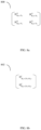
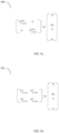
- FIG. 8a illustrates an aggregated matrix 800 to be reconstructed at the master AP or individual APs so that the precoder may be computed for the CBF case.
- FIG. 8b illustrates an aggregated matrix 802 to be reconstructed at the master AP or individual APs so that the precoder may be computed for the JT case.
- APs master AP or individual APs
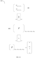
- P CBF1 can be computed with pseudo-inverse of H 11 and H 21 and taking the first K 1 columns.
- P CBE2 can be computed with pseudo-inverse of H 11 and H 21 and taking the last K 2 columns.
- the channel matrix in each AP is reconstructed based on the fed-back eigenvalues, ⁇ , and the Right eigen matrix, V H , without the Left eigen matrix, U.
- these CSI values are aggregated (e.g., concatenated into a single H matrix)
- the U, ⁇ and V H can be thought of as being separately aggregated from the U, ⁇ and V H of each channel individually.
- U is a unitary matrix containing phase information, this can be regarded as a type of carrier frequency offset (CFO) and can be neglected without impacting the overall Multi user-MIMO (MU-MIMO) performance of the CB.
- CFO carrier frequency offset
- MU-MIMO Multi user-MIMO
- the same principle can be applied to a single AP based downlink MU-MIMO.
- the channels to be aggregated are not limited to the columns in the matrix 800, but are also aggregated by the rows of the matrix 800.
- the U matrix is not ignored when the channels are aggregated in rows of the matrix 800. That is, in case the channels H K 1 XN 1 11 308 and H K 1 XN 2 12 310 are aggregated, U, ⁇ and V H cannot be aggregated separately to compute the precoder for JT, and thus we cannot let the feedback to be transmitted for each H K 1 XN 1 11 308 , H K 1 XN 2 12 310 , H K 2 XN 1 21 312 , H K 2 XN 2 22 314 individually.
- FIG. 9b illustrates the precoder matrix for embodiments using JT.
- the CSI information for individual channels may be transmitted between an individual STA and an individual AP separately when using multi-AP collaboration based on CBF or a single AP based DL MU-MIMO.
- the channels between each STA and collaborating APs must be aggregated in each STA first before computing the SVD and calculating CSI information.
- each STA needs to aggregate the estimated channels between the STA and all the APs in the multi-AP collaboration. The STA may then calculate the SVD for the aggregated channels to compute the CSI information to feedback to the APs.
- STA1 304 and STA2 306 should aggregate the estimated channels as in the matrix 802 of FIG. 8b , where H K 1 X N 1 + N 2 1 is aggregated in STA1 304 and H K 2 X N 1 + N 2 2 is aggregated in STA2 306 before each STA computes the CSI information for feedback.
- the matrix 802 may be reconstructed in the master AP based on the fed back CSI information for the H K 1 X N 1 + N 2 1 and H K 2 X N 1 + N 2 2 channels from both STA1 304 and STA2 306.
- the superscript x represents the STA index, that is, the H x is the estimated channel estimated and aggregated in STAx.
- the subscript is the size of the channel.
- the pseudo-inverse of the matrix 802 is used to compute the zero-forcing beamforming (ZFBF) based precoder matrix 1002 in the master AP.
- the channel H K 1 X N 1 + N 2 1 and H K 2 X N 1 + N 2 2 can be estimated using a P-matrix based Concurrent NDP Sounding without the aggregation of the estimated channels.
- concurrent NDP Sounding based on Interleaved Tone based long training field (LTF) may require channel aggregation similar to the serial sounding cases described herein.
- a STA performs channel aggregation prior to computation of the singular value decomposition matrices ⁇ and V.
- the singular value decomposition matrices ⁇ and V are then fed back by the STA to one or more APs.
- This approach is performed in particular when joint transmission (rather than coordinated beamforming) is being implemented by APs for communication.
- the STA is configured to determine whether joint transmission is being implemented for communication. When joint transmission is being implemented by multiple APs together, the STA is further configured to perform channel aggregation prior to computation and feedback of the singular value decomposition matrices ⁇ and V.
- the estimated channel between a STA and all the APs operating together in collaboration mode can be aggregated in each STA before the CSI is fed back for the joint transmission (JT) schedule.
- the STA thus estimates the channel between itself and all the collaborating APs in combination. Then SVD is performed on this aggregated channel.
- the STA is configured to perform a different procedure.
- the STA may be configured to compute and feedback singular value decomposition matrices without channel aggregation. That is, the estimated channel between each STA and each AP can be fed back without aggregation in each STA for the coordinated beamforming schedule.
- the channels between one AP in collaboration mode and all the scheduled STAs in AP collaboration may be reconstructed together in the AP to compute a ZFBF based precoder computation for the coordinated beamforming (CB) schedule.
- CB coordinated beamforming
- all the channels between all the APs and all the scheduled STAs in collaboration mode may be reconstructed together in an AP to compute the joint transmission (JT) schedule.
- JT joint transmission
- a method for determining channel state information (CSI) of a wireless channel by a STA includes receiving a plurality of sounding data transmissions from a plurality of APs over a plurality of communication channels. Estimating, for each of the communication channels, a channel state information (CSI) of the channel based on plurality of sounding data transmissions received over each of the communication channels. Aggregating the channel information of each of the communication channels to produce an aggregated CSI, and transmitting the aggregated CSI to the plurality of APs.
- CSI channel state information
- the term "about” should be read as including variation from the nominal value, for example, a +/-10% variation from the nominal value. It is to be understood that such a variation is always included in a given value provided herein, whether or not it is specifically referred to.
- the present invention may be implemented by using hardware only or by using software and a necessary universal hardware platform. Based on such understandings, the technical solution of the present invention may be embodied in the form of a software product.
- the software product may be stored in a non-volatile or non-transitory storage medium, which can be a compact disk read-only memory (CD-ROM), USB flash disk, or a removable hard disk.
- the software product includes a number of instructions that enable a computer device (personal computer, server, or network device) to execute the methods provided in the embodiments of the present invention. For example, such an execution may correspond to a simulation of the logical operations as described herein.
- the software product may additionally or alternatively include number of instructions that enable a computer device to execute operations for configuring or programming a digital logic apparatus in accordance with embodiments of the present invention.
Landscapes
- Engineering & Computer Science (AREA)
- Computer Networks & Wireless Communication (AREA)
- Signal Processing (AREA)
- Power Engineering (AREA)
- Physics & Mathematics (AREA)
- Mathematical Physics (AREA)
- Mobile Radio Communication Systems (AREA)
Claims (14)
- Procédé de détermination d'informations d'état de canal (CSI) d'un canal sans fil par une station (STA) (304), le procédé comprenant :la réception d'une pluralité de transmissions de données de sondage à partir d'une pluralité de points d'accès (AP) (204, 206) sur une pluralité de canaux de communication (308, 310) ;l'estimation, pour chacun de la pluralité de canaux de communication, de CSI du canal sur la base de la pluralité de transmissions de données de sondage ;le fait d'agréger les CSI de chacun des canaux de communication pour produire des CSI agrégées, et transmettre les CSI agrégées à la pluralité d'AP, en :agrégeant la pluralité de canaux de communication pour produire un canal agrégé ayant une matrice de canaux agrégés (802) ;réalisant une décomposition de valeur singulière sur la matrice de canaux agrégés, en décomposant la matrice de canaux agrégés en UΣVH, où l'exposant H fait référence à l'opération de matrice de transposition hermitienne, pour produire une matrice Σ et une matrice V du canal agrégé ;et caractérisé parla transmission de la matrice Σ et de la matrice V à la pluralité d'AP.
- Procédé selon la revendication 1, dans lequel la pluralité de transmissions de données de sondage sont reçues en série.
- Procédé selon la revendication 1, dans lequel la pluralité de transmissions de données de sondage sont reçues simultanément.
- Procédé selon l'une quelconque des revendications 1 à 3, dans lequel la matrice de canaux agrégés comporte un gain mesuré et une phase mesurée de la pluralité de transmissions de données de sondage.
- Procédé selon l'une quelconque des revendications 1 à 4, dans lequel la pluralité de canaux de communication utilise un protocole WiFi 802.11.
- Procédé selon la revendication 5, dans lequel le protocole 802.11 comporte des protocoles à entrées multiples et sorties multiples (MIMO).
- Procédé selon l'une quelconque des revendications 1 à 6, comprenant également le fait de déterminer qu'une transmission conjointe est utilisée par la pluralité d'AP sur la pluralité de canaux de communication.
- Station (STA) (304) pour communiquer sur un canal de communication, la STA comprenant :
un processeur (110) et une mémoire non transitoire (130) pour stocker des instructions qui, lorsqu'elles sont exécutées par le processeur, amènent la STA à :recevoir une pluralité de transmissions de données de sondage à partir d'une pluralité de points d'accès (AP) (204, 206) sur une pluralité de canaux de communication (308, 310) ;estimer, pour chacun de la pluralité de canaux de communication, des CSI du canal sur la base de la pluralité de transmissions de données de sondage ;agréger les CSI de chacun des canaux de communication pour produire des CSI agrégées, et transmettre les CSI agrégées à la pluralité d'AP, en :agrégeant la pluralité de canaux de communication pour produire un canal agrégé ayant une matrice de canaux agrégés (802) ;réalisant une décomposition de valeur singulière sur la matrice de canaux agrégés, en décomposant la matrice de canaux agrégés en UΣVH, où l'exposant H fait référence à l'opération de matrice de transposition hermitienne, pour produire une matrice Σ et une matrice V du canal agrégé ;et caractérisé parla transmission de la matrice Σ et de la matrice V du canal agrégé à la pluralité d'AP. - Station selon la revendication 8, dans laquelle la pluralité de transmissions de données de sondage sont reçues en série.
- Station selon la revendication 8, dans laquelle la pluralité de transmissions de données de sondage sont reçues simultanément.
- Station selon l'une quelconque des revendications 8 à 10, dans laquelle la matrice de canaux agrégés comporte un gain mesuré et une phase mesurée de la pluralité de transmissions de données de sondage.
- Station selon l'une quelconque des revendications 8 à 11, dans laquelle la pluralité de canaux de communication utilise un protocole WiFi 802.11.
- Station selon la revendication 12, dans laquelle le protocole 802.11 comporte des protocoles à entrées multiples et sorties multiples (MIMO).
- Station selon l'une quelconque des revendications 8 à 13, dans laquelle les instructions, lorsqu'elles sont exécutées par le processeur, amènent la STA à déterminer également que la transmission conjointe est utilisée par la pluralité d'AP sur la pluralité de canaux de communication.
Applications Claiming Priority (3)
| Application Number | Priority Date | Filing Date | Title |
|---|---|---|---|
| US201962932845P | 2019-11-08 | 2019-11-08 | |
| US17/089,112 US20210143878A1 (en) | 2019-11-08 | 2020-11-04 | Method and apparatus for channel state information feedback for joint transmission |
| PCT/CN2020/127532 WO2021089046A1 (fr) | 2019-11-08 | 2020-11-09 | Procédé et appareil pour la rétroaction d'information d'état de canal pour la transmission conjointe |
Publications (3)
| Publication Number | Publication Date |
|---|---|
| EP4029151A1 EP4029151A1 (fr) | 2022-07-20 |
| EP4029151A4 EP4029151A4 (fr) | 2022-11-02 |
| EP4029151B1 true EP4029151B1 (fr) | 2025-05-21 |
Family
ID=75847168
Family Applications (1)
| Application Number | Title | Priority Date | Filing Date |
|---|---|---|---|
| EP20885220.2A Active EP4029151B1 (fr) | 2019-11-08 | 2020-11-09 | Procédé et appareil pour la rétroaction d'information d'état de canal pour la transmission conjointe |
Country Status (7)
| Country | Link |
|---|---|
| US (1) | US20210143878A1 (fr) |
| EP (1) | EP4029151B1 (fr) |
| JP (1) | JP7631636B2 (fr) |
| KR (2) | KR20220082044A (fr) |
| CN (1) | CN114667688B (fr) |
| BR (1) | BR112022007480A2 (fr) |
| WO (1) | WO2021089046A1 (fr) |
Families Citing this family (7)
| Publication number | Priority date | Publication date | Assignee | Title |
|---|---|---|---|---|
| JP7421343B2 (ja) * | 2020-01-09 | 2024-01-24 | キヤノン株式会社 | 通信装置、通信装置の制御方法、およびプログラム |
| WO2021146829A1 (fr) * | 2020-01-20 | 2021-07-29 | Qualcomm Incorporated | Rétroaction d'informations d'état de canal pour de multiples points de transmission-réception |
| SG10202003138UA (en) * | 2020-04-03 | 2021-11-29 | Panasonic Ip Corp America | Communication apparatus and communication method for channel sounding |
| US20240292254A1 (en) * | 2021-06-09 | 2024-08-29 | Lg Electronics Inc. | Method and device for transmitting and receiving channel state information in wireless lan system |
| US12074820B2 (en) | 2021-09-24 | 2024-08-27 | Huawei Technologies Co., Ltd. | Protocol and frame format for coordinated beamforming |
| CN119277394A (zh) * | 2023-07-07 | 2025-01-07 | 锐捷网络股份有限公司 | 信道状态信息获取方法、装置及可读存储介质 |
| WO2025137388A1 (fr) * | 2023-12-19 | 2025-06-26 | Maxlinear, Inc. | Transmission à entrées multiples et sorties multiples (mimo) coordonnée pour stations (sta) |
Family Cites Families (16)
| Publication number | Priority date | Publication date | Assignee | Title |
|---|---|---|---|---|
| US8379705B2 (en) * | 2009-08-04 | 2013-02-19 | Qualcomm Incorporated | Hierarchical feedback of channel state information for wireless communication |
| CN102006108B (zh) * | 2009-08-28 | 2012-10-03 | 华为技术有限公司 | 信道状态信息的传输方法、装置和系统 |
| CN103503332B (zh) * | 2011-05-04 | 2016-05-18 | Lg电子株式会社 | 在无线通信系统中发射/接收信道状态信息的方法和装置 |
| CN102546110A (zh) * | 2011-12-31 | 2012-07-04 | 电信科学技术研究院 | 一种传输信道状态信息的方法及装置 |
| US9226302B2 (en) * | 2012-08-24 | 2015-12-29 | Huawei Technologies Co., Ltd. | Systems and methods for interference alignment in Wi-Fi |
| US9258099B2 (en) * | 2012-10-29 | 2016-02-09 | Huawei Technologies Co., Ltd. | System and method for user cooperation protocol for interference alignment in wireless networks |
| US9455808B2 (en) * | 2013-07-03 | 2016-09-27 | Broadcom Corporation | Wireless communication system with coordinated multipoint operation and methods for use therewith |
| US9456452B2 (en) * | 2014-02-25 | 2016-09-27 | Snu R&Db Foundation | Scheduling method of multi-user multi-input multi-output communication system |
| US9912393B2 (en) * | 2014-03-26 | 2018-03-06 | Nokia Solutions And Networks Oy | Radio frequency beamforming basis function feedback |
| US20160149628A1 (en) * | 2014-11-25 | 2016-05-26 | Intel Corporation | Channel state information (csi) reporting for carrier aggregation |
| US9793965B1 (en) * | 2016-04-01 | 2017-10-17 | Quantenna Communications, Inc. | Frequency orthogonalized MIMO channel sounding and feedback in a wireless home network |
| EP3306829B1 (fr) * | 2016-10-07 | 2019-08-28 | Mitsubishi Electric R&D Centre Europe B.V. | Procédé de transmission de données par un système de communication sans fil basé sur un canal mimo |
| US10911120B2 (en) * | 2017-07-24 | 2021-02-02 | Qualcomm Incorporated | Downlink (DL) coordinated beamforming protocols for WiFi |
| US10574321B2 (en) * | 2017-11-14 | 2020-02-25 | Telefonaktiebolaget Lm Ericsson (Publ) | UE reporting aggregated channel state information based on multiple P3 sweeps |
| US10879979B2 (en) * | 2018-04-12 | 2020-12-29 | Lg Electronics Inc. | Signal transmission/reception method in wireless LAN system, and device therefor |
| US11451285B2 (en) * | 2019-10-29 | 2022-09-20 | Mediatek Singapore Pte. Ltd. | Efficient extreme high-throughput sounding feedback supporting JMAP and CMAP transmissions |
-
2020
- 2020-11-04 US US17/089,112 patent/US20210143878A1/en active Pending
- 2020-11-09 KR KR1020227016068A patent/KR20220082044A/ko not_active Ceased
- 2020-11-09 EP EP20885220.2A patent/EP4029151B1/fr active Active
- 2020-11-09 KR KR1020257036561A patent/KR20250161047A/ko active Pending
- 2020-11-09 CN CN202080078220.XA patent/CN114667688B/zh active Active
- 2020-11-09 BR BR112022007480A patent/BR112022007480A2/pt unknown
- 2020-11-09 JP JP2022522707A patent/JP7631636B2/ja active Active
- 2020-11-09 WO PCT/CN2020/127532 patent/WO2021089046A1/fr not_active Ceased
Also Published As
| Publication number | Publication date |
|---|---|
| JP7631636B2 (ja) | 2025-02-19 |
| JP2022554078A (ja) | 2022-12-28 |
| US20210143878A1 (en) | 2021-05-13 |
| EP4029151A4 (fr) | 2022-11-02 |
| KR20250161047A (ko) | 2025-11-14 |
| KR20220082044A (ko) | 2022-06-16 |
| CN114667688A (zh) | 2022-06-24 |
| CN114667688B (zh) | 2023-09-08 |
| BR112022007480A2 (pt) | 2022-07-12 |
| WO2021089046A1 (fr) | 2021-05-14 |
| EP4029151A1 (fr) | 2022-07-20 |
Similar Documents
| Publication | Publication Date | Title |
|---|---|---|
| EP4029151B1 (fr) | Procédé et appareil pour la rétroaction d'information d'état de canal pour la transmission conjointe | |
| CN115088224B (zh) | 一种信道状态信息反馈方法及通信装置 | |
| US8891653B2 (en) | MU-MIMO transmission method in wireless LAN system | |
| CN104704870B (zh) | 用于Wi-Fi中干扰对齐的系统和方法 | |
| US20230164004A1 (en) | Channel parameter obtaining method and apparatus | |
| US20120294255A1 (en) | Link adaptation method and apparatus in wireless lan system | |
| WO2019042258A1 (fr) | Procédé et dispositif de rétroaction de mesurage de csi-rs | |
| WO2023011570A1 (fr) | Procédé de rétroaction d'informations de canal et appareil de communication | |
| US20250227514A1 (en) | Communication method and related device | |
| JP2024537705A (ja) | 協調ビームフォーミングのためのプロトコルおよびフレームフォーマット | |
| WO2025223118A1 (fr) | Procédé et appareil de communication | |
| WO2011136473A2 (fr) | Procédé d'évitement de brouillage dans un système de communication sans fil et appareil correspondant | |
| WO2023185434A1 (fr) | Procédé et appareil de transmission de données | |
| WO2026021144A1 (fr) | Procédé et appareil de communication pour renvoyer une matrice de précodage | |
| CN120050695A (zh) | 通信方法及相关设备 | |
| WO2025113117A1 (fr) | Procédé de communication et dispositif associé | |
| WO2026092859A1 (fr) | Dispositifs et procédés pour un sondage de canal amélioré dans un réseau local sans fil | |
| WO2025168080A1 (fr) | Procédé et appareil de communication | |
| WO2025060883A1 (fr) | Procédé et dispositif de communication | |
| WO2025148745A1 (fr) | Procédé de communication et appareil de communication | |
| CN119544162A (zh) | 一种通信方法及相关设备 | |
| KR20210048988A (ko) | 클라우드 무선 액세스 네트워크 시스템에서 통신 방법 및 장치 |
Legal Events
| Date | Code | Title | Description |
|---|---|---|---|
| STAA | Information on the status of an ep patent application or granted ep patent |
Free format text: STATUS: THE INTERNATIONAL PUBLICATION HAS BEEN MADE |
|
| PUAI | Public reference made under article 153(3) epc to a published international application that has entered the european phase |
Free format text: ORIGINAL CODE: 0009012 |
|
| STAA | Information on the status of an ep patent application or granted ep patent |
Free format text: STATUS: REQUEST FOR EXAMINATION WAS MADE |
|
| 17P | Request for examination filed |
Effective date: 20220412 |
|
| AK | Designated contracting states |
Kind code of ref document: A1 Designated state(s): AL AT BE BG CH CY CZ DE DK EE ES FI FR GB GR HR HU IE IS IT LI LT LU LV MC MK MT NL NO PL PT RO RS SE SI SK SM TR |
|
| REG | Reference to a national code |
Ref country code: DE Ref legal event code: R079 Free format text: PREVIOUS MAIN CLASS: H04B0007040000 Ipc: H04B0007024000 Ref document number: 602020051837 Country of ref document: DE |
|
| A4 | Supplementary search report drawn up and despatched |
Effective date: 20221005 |
|
| RIC1 | Information provided on ipc code assigned before grant |
Ipc: H04W 84/12 20090101ALN20220928BHEP Ipc: H04W 24/10 20090101ALN20220928BHEP Ipc: H04B 7/06 20060101ALI20220928BHEP Ipc: H04B 7/024 20170101AFI20220928BHEP |
|
| DAV | Request for validation of the european patent (deleted) | ||
| DAX | Request for extension of the european patent (deleted) | ||
| RIC1 | Information provided on ipc code assigned before grant |
Ipc: H04W 84/12 20090101ALN20240620BHEP Ipc: H04W 24/10 20090101ALN20240620BHEP Ipc: H04B 7/06 20060101ALI20240620BHEP Ipc: H04B 7/024 20170101AFI20240620BHEP |
|
| GRAP | Despatch of communication of intention to grant a patent |
Free format text: ORIGINAL CODE: EPIDOSNIGR1 |
|
| RIC1 | Information provided on ipc code assigned before grant |
Ipc: H04W 84/12 20090101ALN20240625BHEP Ipc: H04W 24/10 20090101ALN20240625BHEP Ipc: H04B 7/06 20060101ALI20240625BHEP Ipc: H04B 7/024 20170101AFI20240625BHEP |
|
| STAA | Information on the status of an ep patent application or granted ep patent |
Free format text: STATUS: GRANT OF PATENT IS INTENDED |
|
| RIC1 | Information provided on ipc code assigned before grant |
Ipc: H04W 84/12 20090101ALN20240711BHEP Ipc: H04W 24/10 20090101ALN20240711BHEP Ipc: H04B 7/06 20060101ALI20240711BHEP Ipc: H04B 7/024 20170101AFI20240711BHEP |
|
| INTG | Intention to grant announced |
Effective date: 20240801 |
|
| GRAJ | Information related to disapproval of communication of intention to grant by the applicant or resumption of examination proceedings by the epo deleted |
Free format text: ORIGINAL CODE: EPIDOSDIGR1 |
|
| STAA | Information on the status of an ep patent application or granted ep patent |
Free format text: STATUS: REQUEST FOR EXAMINATION WAS MADE |
|
| GRAP | Despatch of communication of intention to grant a patent |
Free format text: ORIGINAL CODE: EPIDOSNIGR1 |
|
| STAA | Information on the status of an ep patent application or granted ep patent |
Free format text: STATUS: GRANT OF PATENT IS INTENDED |
|
| INTC | Intention to grant announced (deleted) | ||
| RIC1 | Information provided on ipc code assigned before grant |
Ipc: H04W 84/12 20090101ALN20241122BHEP Ipc: H04W 24/10 20090101ALN20241122BHEP Ipc: H04B 7/06 20060101ALI20241122BHEP Ipc: H04B 7/024 20170101AFI20241122BHEP |
|
| INTG | Intention to grant announced |
Effective date: 20241216 |
|
| GRAS | Grant fee paid |
Free format text: ORIGINAL CODE: EPIDOSNIGR3 |
|
| GRAA | (expected) grant |
Free format text: ORIGINAL CODE: 0009210 |
|
| STAA | Information on the status of an ep patent application or granted ep patent |
Free format text: STATUS: THE PATENT HAS BEEN GRANTED |
|
| AK | Designated contracting states |
Kind code of ref document: B1 Designated state(s): AL AT BE BG CH CY CZ DE DK EE ES FI FR GB GR HR HU IE IS IT LI LT LU LV MC MK MT NL NO PL PT RO RS SE SI SK SM TR |
|
| REG | Reference to a national code |
Ref country code: GB Ref legal event code: FG4D |
|
| REG | Reference to a national code |
Ref country code: CH Ref legal event code: EP |
|
| REG | Reference to a national code |
Ref country code: DE Ref legal event code: R096 Ref document number: 602020051837 Country of ref document: DE |
|
| REG | Reference to a national code |
Ref country code: IE Ref legal event code: FG4D |
|
| REG | Reference to a national code |
Ref country code: NL Ref legal event code: MP Effective date: 20250521 |
|
| PG25 | Lapsed in a contracting state [announced via postgrant information from national office to epo] |
Ref country code: FI Free format text: LAPSE BECAUSE OF FAILURE TO SUBMIT A TRANSLATION OF THE DESCRIPTION OR TO PAY THE FEE WITHIN THE PRESCRIBED TIME-LIMIT Effective date: 20250521 Ref country code: ES Free format text: LAPSE BECAUSE OF FAILURE TO SUBMIT A TRANSLATION OF THE DESCRIPTION OR TO PAY THE FEE WITHIN THE PRESCRIBED TIME-LIMIT Effective date: 20250521 Ref country code: PT Free format text: LAPSE BECAUSE OF FAILURE TO SUBMIT A TRANSLATION OF THE DESCRIPTION OR TO PAY THE FEE WITHIN THE PRESCRIBED TIME-LIMIT Effective date: 20250922 |
|
| REG | Reference to a national code |
Ref country code: LT Ref legal event code: MG9D |
|
| PG25 | Lapsed in a contracting state [announced via postgrant information from national office to epo] |
Ref country code: NO Free format text: LAPSE BECAUSE OF FAILURE TO SUBMIT A TRANSLATION OF THE DESCRIPTION OR TO PAY THE FEE WITHIN THE PRESCRIBED TIME-LIMIT Effective date: 20250821 Ref country code: GR Free format text: LAPSE BECAUSE OF FAILURE TO SUBMIT A TRANSLATION OF THE DESCRIPTION OR TO PAY THE FEE WITHIN THE PRESCRIBED TIME-LIMIT Effective date: 20250822 |
|
| PG25 | Lapsed in a contracting state [announced via postgrant information from national office to epo] |
Ref country code: NL Free format text: LAPSE BECAUSE OF FAILURE TO SUBMIT A TRANSLATION OF THE DESCRIPTION OR TO PAY THE FEE WITHIN THE PRESCRIBED TIME-LIMIT Effective date: 20250521 Ref country code: PL Free format text: LAPSE BECAUSE OF FAILURE TO SUBMIT A TRANSLATION OF THE DESCRIPTION OR TO PAY THE FEE WITHIN THE PRESCRIBED TIME-LIMIT Effective date: 20250521 |
|
| PG25 | Lapsed in a contracting state [announced via postgrant information from national office to epo] |
Ref country code: BG Free format text: LAPSE BECAUSE OF FAILURE TO SUBMIT A TRANSLATION OF THE DESCRIPTION OR TO PAY THE FEE WITHIN THE PRESCRIBED TIME-LIMIT Effective date: 20250521 |
|
| PGFP | Annual fee paid to national office [announced via postgrant information from national office to epo] |
Ref country code: GB Payment date: 20250930 Year of fee payment: 6 |
|
| PG25 | Lapsed in a contracting state [announced via postgrant information from national office to epo] |
Ref country code: HR Free format text: LAPSE BECAUSE OF FAILURE TO SUBMIT A TRANSLATION OF THE DESCRIPTION OR TO PAY THE FEE WITHIN THE PRESCRIBED TIME-LIMIT Effective date: 20250521 |
|
| PGFP | Annual fee paid to national office [announced via postgrant information from national office to epo] |
Ref country code: FR Payment date: 20250930 Year of fee payment: 6 |
|
| PG25 | Lapsed in a contracting state [announced via postgrant information from national office to epo] |
Ref country code: RS Free format text: LAPSE BECAUSE OF FAILURE TO SUBMIT A TRANSLATION OF THE DESCRIPTION OR TO PAY THE FEE WITHIN THE PRESCRIBED TIME-LIMIT Effective date: 20250821 |
|
| PG25 | Lapsed in a contracting state [announced via postgrant information from national office to epo] |
Ref country code: IS Free format text: LAPSE BECAUSE OF FAILURE TO SUBMIT A TRANSLATION OF THE DESCRIPTION OR TO PAY THE FEE WITHIN THE PRESCRIBED TIME-LIMIT Effective date: 20250921 |
|
| PG25 | Lapsed in a contracting state [announced via postgrant information from national office to epo] |
Ref country code: LV Free format text: LAPSE BECAUSE OF FAILURE TO SUBMIT A TRANSLATION OF THE DESCRIPTION OR TO PAY THE FEE WITHIN THE PRESCRIBED TIME-LIMIT Effective date: 20250521 |
|
| REG | Reference to a national code |
Ref country code: AT Ref legal event code: MK05 Ref document number: 1797714 Country of ref document: AT Kind code of ref document: T Effective date: 20250521 |
|
| PGFP | Annual fee paid to national office [announced via postgrant information from national office to epo] |
Ref country code: DE Payment date: 20250930 Year of fee payment: 6 |
|
| PG25 | Lapsed in a contracting state [announced via postgrant information from national office to epo] |
Ref country code: DK Free format text: LAPSE BECAUSE OF FAILURE TO SUBMIT A TRANSLATION OF THE DESCRIPTION OR TO PAY THE FEE WITHIN THE PRESCRIBED TIME-LIMIT Effective date: 20250521 Ref country code: SM Free format text: LAPSE BECAUSE OF FAILURE TO SUBMIT A TRANSLATION OF THE DESCRIPTION OR TO PAY THE FEE WITHIN THE PRESCRIBED TIME-LIMIT Effective date: 20250521 Ref country code: AT Free format text: LAPSE BECAUSE OF FAILURE TO SUBMIT A TRANSLATION OF THE DESCRIPTION OR TO PAY THE FEE WITHIN THE PRESCRIBED TIME-LIMIT Effective date: 20250521 |
|
| PG25 | Lapsed in a contracting state [announced via postgrant information from national office to epo] |
Ref country code: CZ Free format text: LAPSE BECAUSE OF FAILURE TO SUBMIT A TRANSLATION OF THE DESCRIPTION OR TO PAY THE FEE WITHIN THE PRESCRIBED TIME-LIMIT Effective date: 20250521 |
|
| PG25 | Lapsed in a contracting state [announced via postgrant information from national office to epo] |
Ref country code: EE Free format text: LAPSE BECAUSE OF FAILURE TO SUBMIT A TRANSLATION OF THE DESCRIPTION OR TO PAY THE FEE WITHIN THE PRESCRIBED TIME-LIMIT Effective date: 20250521 |
|
| PG25 | Lapsed in a contracting state [announced via postgrant information from national office to epo] |
Ref country code: RO Free format text: LAPSE BECAUSE OF FAILURE TO SUBMIT A TRANSLATION OF THE DESCRIPTION OR TO PAY THE FEE WITHIN THE PRESCRIBED TIME-LIMIT Effective date: 20250521 Ref country code: SK Free format text: LAPSE BECAUSE OF FAILURE TO SUBMIT A TRANSLATION OF THE DESCRIPTION OR TO PAY THE FEE WITHIN THE PRESCRIBED TIME-LIMIT Effective date: 20250521 |
|
| PG25 | Lapsed in a contracting state [announced via postgrant information from national office to epo] |
Ref country code: IT Free format text: LAPSE BECAUSE OF FAILURE TO SUBMIT A TRANSLATION OF THE DESCRIPTION OR TO PAY THE FEE WITHIN THE PRESCRIBED TIME-LIMIT Effective date: 20250521 |
|
| REG | Reference to a national code |
Ref country code: DE Ref legal event code: R097 Ref document number: 602020051837 Country of ref document: DE |
|
| PLBE | No opposition filed within time limit |
Free format text: ORIGINAL CODE: 0009261 |
|
| STAA | Information on the status of an ep patent application or granted ep patent |
Free format text: STATUS: NO OPPOSITION FILED WITHIN TIME LIMIT |
|
| REG | Reference to a national code |
Ref country code: CH Ref legal event code: L10 Free format text: ST27 STATUS EVENT CODE: U-0-0-L10-L00 (AS PROVIDED BY THE NATIONAL OFFICE) Effective date: 20260402 |
|
| 26N | No opposition filed |
Effective date: 20260224 |