EP4029224B1 - Zuweisung virtueller adressen zum vermeiden von konflikten in umgebungen mit mehreren netzwerken - Google Patents
Zuweisung virtueller adressen zum vermeiden von konflikten in umgebungen mit mehreren netzwerken Download PDFInfo
- Publication number
- EP4029224B1 EP4029224B1 EP20704254.0A EP20704254A EP4029224B1 EP 4029224 B1 EP4029224 B1 EP 4029224B1 EP 20704254 A EP20704254 A EP 20704254A EP 4029224 B1 EP4029224 B1 EP 4029224B1
- Authority
- EP
- European Patent Office
- Prior art keywords
- network
- address
- network node
- node
- virtual
- Prior art date
- Legal status (The legal status is an assumption and is not a legal conclusion. Google has not performed a legal analysis and makes no representation as to the accuracy of the status listed.)
- Active
Links
Images



Classifications
-
- H—ELECTRICITY
- H04—ELECTRIC COMMUNICATION TECHNIQUE
- H04L—TRANSMISSION OF DIGITAL INFORMATION, e.g. TELEGRAPHIC COMMUNICATION
- H04L61/00—Network arrangements, protocols or services for addressing or naming
- H04L61/09—Mapping addresses
- H04L61/25—Mapping addresses of the same type
- H04L61/2503—Translation of Internet protocol [IP] addresses
- H04L61/2521—Translation architectures other than single NAT servers
- H04L61/2535—Multiple local networks, e.g. resolving potential IP address conflicts
-
- H—ELECTRICITY
- H04—ELECTRIC COMMUNICATION TECHNIQUE
- H04L—TRANSMISSION OF DIGITAL INFORMATION, e.g. TELEGRAPHIC COMMUNICATION
- H04L2101/00—Indexing scheme associated with group H04L61/00
- H04L2101/60—Types of network addresses
- H04L2101/618—Details of network addresses
- H04L2101/659—Internet protocol version 6 [IPv6] addresses
-
- H—ELECTRICITY
- H04—ELECTRIC COMMUNICATION TECHNIQUE
- H04L—TRANSMISSION OF DIGITAL INFORMATION, e.g. TELEGRAPHIC COMMUNICATION
- H04L2101/00—Indexing scheme associated with group H04L61/00
- H04L2101/60—Types of network addresses
- H04L2101/668—Internet protocol [IP] address subnets
-
- H—ELECTRICITY
- H04—ELECTRIC COMMUNICATION TECHNIQUE
- H04L—TRANSMISSION OF DIGITAL INFORMATION, e.g. TELEGRAPHIC COMMUNICATION
- H04L2101/00—Indexing scheme associated with group H04L61/00
- H04L2101/60—Types of network addresses
- H04L2101/677—Multiple interfaces, e.g. multihomed nodes
-
- H—ELECTRICITY
- H04—ELECTRIC COMMUNICATION TECHNIQUE
- H04L—TRANSMISSION OF DIGITAL INFORMATION, e.g. TELEGRAPHIC COMMUNICATION
- H04L61/00—Network arrangements, protocols or services for addressing or naming
- H04L61/50—Address allocation
- H04L61/5007—Internet protocol [IP] addresses
- H04L61/5014—Internet protocol [IP] addresses using dynamic host configuration protocol [DHCP] or bootstrap protocol [BOOTP]
Definitions
- the networks may be highly dynamic with network nodes continuously connecting and disconnecting from the network requiring automated methods and systems as known in the art to map the network nodes in the network, for example, Dynamic Host Configuration Protocol (DHCP) systems, Internet Key Exchange (IKE), Wi-Fi Protected Access (WPA) and/or the like.
- DHCP Dynamic Host Configuration Protocol
- IKE Internet Key Exchange
- WPA Wi-Fi Protected Access
- the challenge to effectively and uniquely assign network addresses to the network nodes may significantly increase for network nodes connected simultaneously to a plurality of networks (multi-network nodes) which may be separated from each other and independently controlled such that conflicts may arise when mapping the multi-network nodes in the different networks.
- An objective of the embodiments of the present disclosure is to provide a solution which mitigates or solves the drawbacks and problems of conventional solutions.
- the present disclosure aims at providing a solution for automatically supporting network connection for one or more network nodes connected to one or more other networks by creating a virtual sub-network for each multi-network node and assigning it a virtual network address in the virtual sub-network such that the virtual network address does not conflict (collide) with network addresses assigned to the multi-network node in the other network(s).
- Implementation of the method and/or system of embodiments of the present disclosure can involve performing or completing selected tasks manually, automatically, or a combination thereof. Moreover, according to actual instrumentation and equipment of embodiments of the method and/or system of the present disclosure, several selected tasks could be implemented by hardware, by software or by firmware or by a combination thereof using an operating system.
- a data processor such as a computing platform for executing a plurality of instructions.
- the data processor includes a volatile memory for storing instructions and/or data and/or a non-volatile storage, for example, a magnetic hard-disk and/or removable media, for storing instructions and/or data.
- a network connection is provided as well.
- a display and/or a user input device such as a keyboard or mouse are optionally provided as well.
- the present disclosure in some embodiments thereof, relates to allocating network addresses to network nodes connected to a network and, more specifically, but not exclusively, to allocating virtual network addresses to network nodes connected to a plurality of networks in a virtual sub-network established over the network for the multi-network nodes to avoid network address conflicts.
- the present disclosure presents devices, systems and methods for creating virtual sub-networks over a first network for (multi-)network nodes requesting to connect to the first network while connected to one or more other (second) networks which are separated from the first network and independently managed.
- the virtual sub-networks are created based on routing information received from the multi-network nodes in order to assign network addresses to the multi-network nodes such that the network addresses assigned on the first network do not conflict with the network addresses assigned to these multi-network nodes on the second networks.
- Each multi-network node which may include physical devices, for example, a server, a computer, a mobile device and/or the like as well as virtual nodes, for example, a Virtual Machine (VM) and/or the like instantiated over one or more physical devices may connect to the first network and the second network(s) via different network interfaces available to the multi-network node.
- VM Virtual Machine
- Modem networks whether physical and/or virtual are typically based on one or more addressing schemes as known in the art in which each network node connected to the network is assigned a unique network address which is used to uniquely and distinctively identify each of the connected network nodes in order to enable the network nodes to exchange packets over the network.
- Each network is typically allocated a network address range (e.g. IP address range) and each network node connected to the network is assigned a network address (e.g. IP address) within the network address range allocated for the network.
- the address allocation and assignment is mostly automatically conducted by one or more network apparatuses configured to automatically assign a network address to each network node which connects to the network.
- the network apparatus may be a physical or a virtual entity utilized by one or more devices, software implemented modules, dedicated circuits and/or combination thereof, for example, a server, a Dynamic Host Configuration Protocol (DHCP) server, a gateway, a router a switch, a virtual switch and/or the like.
- DHCP Dynamic Host Configuration Protocol
- the first network and the second network(s) to which a multi-network node is connected or attempts (requests) to connect are separated from each other and independently managed, for example, controlled by independent network apparatuses which are unaware of each other and/or un-synchronized with each other with respect to network address allocation.
- the first network and the second network(s) may therefore be allocated with conflicting (colliding, overlapping) address ranges.
- the network address assigned to the multi-network node specifically to one network interface of the multi-network node in the first network may conflict (collide) with the network address assigned to the multi-network node, specifically to other network interface of the multi-network nodes in one of the second network(s).
- the address conflict may obviously lead to conflict in the internal network data routing of the multi-network node which be unable to distinguish between packets transmitted/received on the first network and the respective second network. This may lead to degrade network connectivity and potentially complete inability of the multi-network node to communicate over one or more of the first and/or second network.
- Creating the virtual sub-network may resolve all such potential address conflicts as each multi-network node is assigned virtual network address which is determined not to conflict with other network address(s) assigned to the respective multi-network node in the other networks(s) it is connected to.
- some of the existing systems and methods may be based on manual configuration of the network addresses allocated for the plurality of different networks in order to prevent address conflicts. Such manual configuration may involve major effort and may be extremely time consuming. Moreover, since modem networks are highly dynamic with network nodes continuously connecting and disconnecting, manual configuring these network nodes may be inefficient, impractical and typically unfeasible. In contrast, automatically establishing virtual sub-networks over the network for the multi-network nodes and assigning them virtual network addresses may enable automatic adaptation to any network configuration change and is thus highly suitable for the dynamically changing modem networks.
- the other network node(s) connected to the network are unaware and oblivious to the virtual sub-network(s) established over the network for the multi-network node(s) and may communicate with the multi-network node(s) using the real network addresses which are normally used in the network, the other network node(s) may require no modifications, alterations and/or adjustments to enable them to communicate with the multi-network node(s).
- the virtual mapping over the virtual sub-networks may be therefore easily deployed in existing networks requiring only the network apparatus to support the virtual mapping of the virtual sub-networks created for the multi-network nodes. This may significantly reduce, complexity, cost, resources and/or cost for automatically supporting connection of multi-network nodes to the network while avoiding address conflicts to ensure full functionality of the network.
- aspects of the present disclosure may be embodied as a system, method or computer program product. Accordingly, aspects of the present disclosure may take the form of an entirely hardware embodiment, an entirely software embodiment (including firmware, resident software, micro-code, etc.) or an embodiment combining software and hardware aspects that may all generally be referred to herein as a "circuit,” “module” or “system.” Furthermore, aspects of the present disclosure may take the form of a computer program product embodied in one or more computer readable medium(s) having computer readable program code embodied thereon.
- the computer readable storage medium can be a tangible device that can retain and store instructions for use by an instruction execution device.
- the computer readable storage medium may be, for example, but is not limited to, an electronic storage device, a magnetic storage device, an optical storage device, an electromagnetic storage device, a semiconductor storage device, or any suitable combination of the foregoing.
- a non-exhaustive list of more specific examples of the computer readable storage medium includes the following: a portable computer diskette, a hard disk, a random access memory (RAM), a read-only memory (ROM), an erasable programmable read-only memory (EPROM or Flash memory), a static random access memory (SRAM), a portable compact disc read-only memory (CD-ROM), a digital versatile disk (DVD), a memory stick, a floppy disk, a mechanically encoded device such as punch-cards or raised structures in a groove having instructions recorded thereon, and any suitable combination of the foregoing.
- RAM random access memory
- ROM read-only memory
- EPROM or Flash memory erasable programmable read-only memory
- SRAM static random access memory
- CD-ROM compact disc read-only memory
- DVD digital versatile disk
- memory stick a floppy disk
- a mechanically encoded device such as punch-cards or raised structures in a groove having instructions recorded thereon
- a computer readable storage medium is not to be construed as being transitory signals per se, such as radio waves or other freely propagating electromagnetic waves, electromagnetic waves propagating through a waveguide or other transmission media (e.g., light pulses passing through a fiber-optic cable), or electrical signals transmitted through a wire.
- Computer program code comprising computer readable program instructions embodied on a computer readable medium may be transmitted using any appropriate medium, including but not limited to wireless, wire line, optical fiber cable, RF, etc., or any suitable combination of the foregoing.
- the computer readable program instructions described herein can be downloaded to respective computing/processing devices from a computer readable storage medium or to an external computer or external storage device via a network, for example, the Internet, a local area network, a wide area network and/or a wireless network.
- the network may comprise copper transmission cables, optical transmission fibers, wireless transmission, routers, firewalls, switches, gateway computers and/or edge servers.
- a network adapter card or network interface in each computing/processing device receives computer readable program instructions from the network and forwards the computer readable program instructions for storage in a computer readable storage medium within the respective computing/processing device.
- the computer readable program instructions for carrying out operations of the present disclosure may be may be written in any combination of one or more programming languages, such as, for example, assembler instructions, instruction-set-architecture (ISA) instructions, machine instructions, machine dependent instructions, microcode, firmware instructions, state-setting data, or either source code or object code written in any combination of one or more programming languages, including an object oriented programming language such as Smalltalk, C++ or the like, and conventional procedural programming languages, such as the "C" programming language or similar programming languages.
- ISA instruction-set-architecture
- machine instructions machine dependent instructions
- microcode firmware instructions
- state-setting data or either source code or object code written in any combination of one or more programming languages, including an object oriented programming language such as Smalltalk, C++ or the like, and conventional procedural programming languages, such as the "C" programming language or similar programming languages.
- the computer readable program instructions may execute entirely on the user's computer, partly on the user's computer, as a stand-alone software package, partly on the user's computer and partly on a remote computer or entirely on the remote computer or server.
- the remote computer may be connected to the user's computer through any type of network, including a local area network (LAN) or a wide area network (WAN), or the connection may be made to an external computer (for example, through the Internet using an Internet Service Provider).
- LAN local area network
- WAN wide area network
- Internet Service Provider for example, AT&T, MCI, Sprint, EarthLink, MSN, GTE, etc.
- electronic circuitry including, for example, programmable logic circuitry, field-programmable gate arrays (FPGA), or programmable logic arrays (PLA) may execute the computer readable program instructions by utilizing state information of the computer readable program instructions to personalize the electronic circuitry, in order to perform aspects of the present disclosure.
- FPGA field-programmable gate arrays
- PLA programmable logic arrays
- each block in the flowchart or block diagrams may represent a module, segment, or portion of instructions, which comprises one or more executable instructions for implementing the specified logical function(s).
- the functions noted in the block may occur out of the order noted in the figures.
- two blocks shown in succession may, in fact, be executed substantially concurrently, or the blocks may sometimes be executed in the reverse order, depending upon the functionality involved.
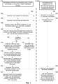
- FIG. 1 presents flow charts of exemplary processes of creating a virtual sub-network to assign a non-conflicting network address to a network node connected to a plurality of networks based on routing information received from the network node, according to some embodiments of the present disclosure.
- network address conflict is also known as network address collision and the two terms may be used interchangeably throughout this document.
- An exemplary process 150 may be executed by a network node 210, for example, a server, a computer, a mobile device and/or the like, specifically a multi-network node 210BA requesting to connect to a first network while connected to a one or more other (second) networks which are separated and independently controlled (managed) from the first network.
- a network node 210 for example, a server, a computer, a mobile device and/or the like, specifically a multi-network node 210BA requesting to connect to a first network while connected to a one or more other (second) networks which are separated and independently controlled (managed) from the first network.
- An exemplary process 100 may be executed by a network apparatus 212, for example, a gateway, a switch, a network node, a server and/or the like controlling a (first) network to assign a network address (e.g. IP address) to the multi-network node 210BA requesting to connect to the first network while connected to the second network(s) such that the assigned network address does not conflict with the network address(s) assigned to the multi-network node 210BA on the second network(s).
- a network apparatus 212 for example, a gateway, a switch, a network node, a server and/or the like controlling a (first) network to assign a network address (e.g. IP address) to the multi-network node 210BA requesting to connect to the first network while connected to the second network(s) such that the assigned network address does not conflict with the network address(s) assigned to the multi-network node 210BA on the second network(s).
- a network apparatus 212 for example,
- the network apparatus 212 first analyses routing information received from the network node 210 which may comprise network mapping (networking addressing) of the multi-network node 210BA such as, for example, the network address(s) assigned to the multi-network node 210BA on the second network(s).
- network mapping networking addressing
- the network apparatus 212 may simply assign the multi-network node 210BA a real network address (e.g. IP address) in the network address range allocated to the first network.
- a real network address e.g. IP address
- the term real network address refers to a network address which is not manipulated and is assigned in the address range originally applied for mapping network nodes in the first network.
- the multi-network node 210BA may use the received real (basic) network address to communicate with one or more other network nodes 210 connected to the first network.
- the network apparatus 212 creates a virtual sub-network for the multi-network node 210BA over the first network.
- the network apparatus 212 allocates to the virtual sub-network a network address range which, based on analysis of the routing information, does not conflict with the network addresses allocated to the multi-network node 210BA on the second network(s).
- the network apparatus 212 then assigns a virtual address (e.g. IP address) to the multi-network node 210BA in the address space of the virtual sub-network and further assigns a virtual address in the virtual sub-network to one or more of the other network nodes 210 connected to the first network.
- a virtual address e.g. IP address
- the network apparatus 212 assigns the multi-network node 210BA the real network address in the network address space of the first network which may be used by one or more of the other network nodes 210 connected to the first network to access the network node 210.
- the multi-network node 210BA uses the virtual addresses assigned in the virtual sub-network for communicating with the other network node(s) 210 connected to the first network.
- the other network node(s) 210 are completely unaware of the virtual sub-network and use the real network address assigned to the multi-network node 210BA to communicate with it such no change and/or adjustment is required for the other network node(s) 210 to enable connection of the multi-network node 210BA to the first network.
- the communication i.e., the network traffic packets exchanged between the multi-network node 210BA and the other network node(s) 210 connected to the first network via the virtual sub-network established over the first network are controlled (managed) by the network apparatus 212A which translates the virtual addresses to the respective real network addresses and vice versa.
- the network apparatus 212A may further provide one or more services to the network nodes 210 connected to the first network including the multi-network node 210BA, for example, network discovery services, DNS services, HTTP response services, Ad-hoc connectivity services and/or the like to support communication between the network nodes 210 connected to the first network and to the virtual sub-network established over the first network.
- communication i.e., the network traffic packets exchanged between the multi-network node 210BA and the other network node(s) 210 connected to the first network via the virtual sub-network established over the first network may be controlled (managed) by the network apparatus 212 which may translate the virtual addresses to the respective real network addresses and vice versa.
- FIG. 2 is a schematic illustration of an exemplary networked system for creating a virtual sub-network to assign a non-conflicting network address to a network node connected to a plurality of networks based on routing information received from the network node, according to some embodiments of the present disclosure.
- An exemplary networked system 200 comprises a first network 202A and a second network 202B which may each include a wired and/or wireless network, for example, a Local Area Network (LAN), a Wide Area Network (WAN), a Municipal Area Network (MAN), a Wireless LAN (WLAN, e.g., Wi-Fi), a cellular network and/or the like which may be utilized by one or more physical networks and/or virtual networks such as, for example, a Software Defined Network (SDN) and/or the like.
- LAN Local Area Network
- WAN Wide Area Network
- MAN Municipal Area Network
- WLAN Wireless LAN
- cellular network e.g., cellular network and/or the like
- SDN Software Defined Network
- Each of the networks 202 may be managed by a respective network apparatus 212, for example, a gateway, a switch, a network node, a server, a Dynamic Host Configuration Protocol (DHCP) server and/or the like, specifically the first network 202A may be managed by a network apparatus 212A and the second network 202B may be managed by a network apparatus 212B.
- a gateway for example, a gateway, a switch, a network node, a server, a Dynamic Host Configuration Protocol (DHCP) server and/or the like
- DHCP Dynamic Host Configuration Protocol
- the first network 202A and the second network 202B are separated of each other and independently managed by their respective network apparatuses 212A and 212B such that they are oblivious to each other.
- the network apparatuses 212A and 212B may be unaware and therefore unsynchronized with respect to the network mapping applied in each of the first network 202A and the second network 202B, for example, the network addresses assigned to one or more network nodes 210 which are connected to the first network 202A and/or to the second network 202B.
- the network nodes 210 may include, for example, a server, a computer, a mobile device (e.g. laptop, Smartphone, tablet, etc.) and/or the like.
- the network nodes 210 may further include one or more virtual network nodes such as, for example, a Virtual Machine (VM) and/or the like instantiated on one or more of physical network nodes 210 and optionally managed by one or more virtual switches, for example, an Open vSwitch (OVS) and/or the like.
- VM Virtual Machine
- OVS Open vSwitch
- one or more network nodes 210A_n may be connected to the first network 202A, for example, a network node 210A_1, a network node 210A_2 through a network node 210A_N and one or more network nodes 210B_mmay be connected to the second network 202B, for example, a network node 210B_1, a network node 210B_2 through a network node 210B_M.
- one or more network nodes 210 having multiple network interfaces may connect and/or attempt to connect to a plurality of networks 202 each via a respective one of the multiple network interfaces.
- a multi-network node 210BA which is connected to the second network 202B via one network interface may connect or request to connect to the first network 202A via another network interface.
- the multi-network node 210BA may connect to the first network 202A and/or to the second network 202B via the respective network apparatus 212, i.e., via the network apparatus 212A for the first network 202A and the network apparatus 212B for the second network 202B serving as a gateway and/or a switch for the multi-network node 210BA.
- the multi-network node 210BA may connect to the first network 202A via the network apparatus 212A which may include multiple network interfaces to connect the network nodes 210A_n and to the multi-network node 210BA.
- the multi-network node 210BA may connect to the first network 202A and/or to the second network 202B via another network apparatus 212 serving as a gateway and/or a switch for the multi-network node 210BA.
- the multi-network node 210BA may connect to the first network 202A via another network apparatus 212 while the network apparatus 212A is also connected to the first network 202A in parallel to the multi-network node 210BA.
- the network apparatus 212 may optionally comprise one or more processors (homogenous or heterogeneous) arranged for parallel processing, as clusters and/or as one or more distributed core processing units and a storage for storing code (program store) and/or data.
- the processor(s) may execute one or more software modules, for example, a process, a script, an application, an agent, a utility, a tool, an Operating System (OS), a service, a plug-in, an add-on and/or the like, each comprising a plurality of program instructions which may be executed from the program store.
- OS Operating System
- the network apparatus 212 may further include one or more hardware elements, for example, a circuit, a component, an Integrated Circuit (IC), an Application Specific Integrated Circuit (ASIC), a Field Programmable Gate Array (FPGA), a Digital Signals Processor (DSP), a network processor and/or the like.
- IC Integrated Circuit
- ASIC Application Specific Integrated Circuit
- FPGA Field Programmable Gate Array
- DSP Digital Signals Processor
- the network apparatus 212 may thus include a circuitry utilizing one or more software modules, one or more of the hardware elements and/or a combination thereof configured to execute the process 100 and control and manage at least partially the first network 202A, for example, assign network addresses, control network traffic and/or the like.
- one or more of the network nodes 210 may optionally comprise one or more processors (homogenous or heterogeneous) arranged for parallel processing, as clusters and/or as one or more distributed core processing units and a storage for storing code (program store) and/or data.
- the processor(s) may execute one or more software modules each comprising a plurality of program instructions which may be executed from the program store.
- the multi-network node 210BA may further include one or more of the hardware elements.
- One or more of the network nodes 210, specifically, the multi-network node 210BA may thus include a circuitry utilizing one or more software modules, one or more of the hardware elements and/or a combination thereof configured to execute the process 150.
- the exemplary process 100 and the exemplary networked system 200 are described for connecting a single multi-network node 210BA to the two separate and independently managed networks 202A and 202B. This, however should not be construed as limiting since the network apparatus 212A may apply the process 100 for creating a plurality of virtual sub-networks each for a respective network node 210 connected to both the first network 202A and the second network 202B.
- the first network 202A may be expanded to include a plurality of network apparatuses such as the network apparatus 212 each capable of conducting the process 100 for one or more network nodes 210 connected to multiple separate and independently managed networks 202.
- the processes 100 and 150 which are executed by the network apparatus 212A and the multi-network node 210BA respectively are interlinked to and interact with each other.
- the processes 100 and 150 are therefore described in conjunction with each other according to the operational and functional sequence of the overall network address allocation and network traffic exchange combining the two processes 100 and 150.
- Each network 202 is typically based on one or more addressing schemes as known in the art in which each network node 210 connected to the respective network 202 is assigned a unique network address.
- Each packet transmitted over the network 202 includes a source address field which includes the unique network address of the originating (transmitting) network node 210 and a destination address field which includes the unique network address of the destination network node 210 to which the packet is directed (destined).
- the destination address field may include a group of network addresses of multiple destination network nodes 210.
- the destination address field may indicate the message is directed to include all the network nodes 210 connected to the respective network 202.
- the process 150 starts with the multi-network node 210BA transmits one or more messages to the network apparatus 212A requesting to connect to the first network 202A while connected to one or more other (second) networks, for example the network 202B.
- the connection request may typically include a request for a network address which may map the multi-network node 210BA in the first network 202A to enable the multi-network node 210BA to communicate with one or more of the network nodes 210A n connected to the first network 202A.
- the network apparatus 212A controlling and/or managing the first network 202A receives the connection request from the multi-network node 210BA.
- the multi-network node 210BA includes a plurality of network interfaces such that it may be connected to the second network 202B via one of its network interfaces and attempt to connect to the first network 202A via another (a different) one of its network interfaces.
- the multi-network node 210BA further transmits routing information comprising and/or describing network mapping (network addressing) of the multi-network node 210BA on the second network 202B.
- the multi-network node 210BA may apply one or more methods, techniques and/or protocols to transmit the routing information to the network apparatus 212A.
- the multi-network node 210BA may transmit one or more broadcast messages comprising the routing information which may be intercepted by the network apparatus 212.
- the multi-network node 210BA may transmit one or more multicast messages comprising the routing information which may be intercepted by the network apparatus 212.
- the multi-network node 210BA may transmit one or more messages according to one or more negotiation protocols used between the multi-network node 210BA and the network apparatus 212A to establish a connection and/or to map the multi-network node 210BA in the first network 202A.
- Such negotiation protocols may include, for example, IKE, WPA and/or the like.
- the multi-network node 210BA may transmit one or more messages according to one or more extensions to the DHCP protocol applied by the network apparatus 212 to dynamically assign a network address to the multi-network node 210BA.As shown at 104, the network apparatus 212A receives the routing information from the multi-network node 210BA.
- the network apparatus 212A may assign a real IP address to the multi-network node 210BA in a (first) IP address range allocated for the first network 202A.
- the network apparatus 212A further analyses the routing information received from the multi-network node 210BA to determine whether there is a mapping (addressing) conflict between the network mapping (addressing) scheme employed in the first network 202A and the network mapping scheme employed in the second network 202B. Specifically, the network apparatus 212A may analyze the routing information to identify a conflict between the first network address range allocated for the first network 202A and the second network address range applied in the second network 202B.
- the network apparatus 212A may analyze the routing information to identify the second IP address range used in the second network 202B, the IP address assigned to the multi-network node 210BA in the second IP address range and/or the like.
- the process 100 branches to 112. However, in case the network apparatus 212A determines that the first network address range may conflict with the second network address range, the process 100 branches to 114.
- a second IP address range applied in the second network 202B is 10.0.0.0/24 (subnet mask 24) and an IP address 10.0.0.3/24 is assigned to the multi-network node 210BA in the second network 202B.
- the first IP address range applied in the first network 202A is 192.168.0.0/24 and an IP address 192.168.0.20/24 is assigned to the multi-network node 210BA in the first network 202A.
- the multi-network node 210BA may use the IP address 10.0.0.0.3/24 for one of its network interfaces connected to the second network and the IP address 192.168.0.20 for another of its network interfaces connected to the first network 202A.
- the second IP address range applied in the second network 202B is again 10.0.0.0/24 and the IP address 10.0.0.3/24 is assigned to the multi-network node 210BA in the second network 202B.
- the first IP address range applied in the first network 202A is also 10.0.0.0/24 and the IP address 10.0.0.4/24 is assigned to the multi-network node 210BA in the first network 202A.
- the network apparatus 212A may transmit to the multi-network node 210BA the (real) network address assigned (in step 106) to the multi-network node 210BA in the first network address range of the first network 202A.
- the network apparatus 212A creates for the multi-network node 210BA a virtual sub-network established over the first network 202A.
- the network apparatus 212A allocates a third network address range for the created virtual sub-network which is a virtual network address space that is not conflicting (not colliding) with the second address range applied in the second network 202B.
- the third network address range allocated by the network apparatus 212A for the virtual sub-network may be an IPv6 address range which significantly extends the range of available IP addresses which support significantly increased flexibility to prevent conflicts between the third network address range and the second network address range.
- the network apparatus 212A assigns a virtual address to the multi-network node 210BA in the third address space to map the multi-network node 210BA in the virtual sub-network established over the first network 202A.
- the network apparatus 212A further assigns a respective virtual address to one or more of the network nodes 210A_n connected to the first network 202A to map this network node(s) 202A_n in the virtual sub-network created for the multi-network node 210BA to support communication between the multi-network node 210BA and the network node(s) 202A_n mapped in the virtual sub-network.
- the network apparatus 212A transmits to the multi-network node 210BA the virtual address mapping the multi-network node 210BA in the virtual sub-network.
- the multi-network node 210BA receives the network address assigned to it by the network apparatus 212.
- the received address is the (real) network address assigned to the multi-network node 210BA in the first address range to map it in the first network 202A.
- the received address is the virtual network address transmitted by the network apparatus 212A as described in step 120 which is assigned to the multi-network node 210BA in the third network address range to map it in the virtual sub-network established over the first network 202A.
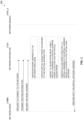
- FIG. 3 is a schematic illustration of an exemplary networked system for creating a virtual sub-network to assign a non-conflicting IP address to a network node connected to a plurality of networks based on routing information received from the network node, according to some embodiments of the present disclosure.
- An exemplary sequence 300 may be initiated by a network node such as the multi-network node 210BA connected to one or more networks such as the second network 202B which requests to connect to another network such as the first network 202A controlled by a network apparatus such as the network apparatus 212A.
- the sequence 300 may start with the multi-network node 210BA transmitting a connection request to the network apparatus 212A requesting to connect to the first network 202A as described in step 152 of the process 150.
- the multi-network node 210BA may further transmit its routing information to the network apparatus 212A as described in step 154 of the process 150.
- the multi-network node 210BA may then request a network address mapping it in the first network 202A to support packets transfer between the multi-network node 210BA and one or more network nodes such as the network nodes 210A_n connected to the first network 202A as described in step 152 of the process 150.
- the network apparatus 212A may assign a real network address to the multi-network node 210BA mapping the multi-network node 210BA in the first network address range utilized in the first network 202A.
- the network apparatus 212A may create for the multi-network node 210BA a virtual sub-network allocated with a third network address range which is non-conflicting (non-colliding) with the second network address range as described in step 114 of the process 100.
- the network apparatus 212A may then assign a unique virtual network address to the multi-network node 210BA thus mapping it in the virtual sub-network as described in step 116 of the process 100.
- the network apparatus 212A may further assign a unique virtual network address to one or more of the network nodes 210A _n connected to the first network 202A to map them in the virtual sub-network created for the multi-network node 210BA as described in step 118 of the process 100.
- the network apparatus 212A may transmit the virtual network address to the multi-network node 210BA as described in step 118 of the process 100.
- the network mapping included in the routing information received from the multi-network node 210BA includes a preferred virtual network address which the multi-network node 210BA requests to be assigned in the first network 202A.
- the preferred virtual network address is determined by the multi-network node 210BA as not conflicting with the network mapping (addressing) applied in the second network 202B.
- the preferred virtual network address is not within the second network address range used in the second network 202B. This means that the analysis of the routing information is done by the multi-network node 210BA which, based on the analysis, selects the preferred virtual network address to be assigned to it to map it in the first network 202A.
- the multi-network node 210BA may apply one or more methods, techniques and/or protocols to transmit the routing information in general and the preferred virtual network address in particular.
- the multi-network node 210BA may transmit the preferred virtual network address in one or more messages according to one or more extensions of the DHCP protocol.
- the network apparatus 212A is relieved of analyzing the routing information which may optionally not be transmitted by the multi-network node 210BA and may create the virtual sub-network for the multi-network node 210BA according to the preferred virtual network address selected by the multi-network node 210BA.
- the network apparatus 212A may define the third network address range according to the preferred virtual network address requested by the multi-network node 210BA.
- the network apparatus 212A may then assign the preferred virtual network address to the multi-network node 210BA and may further assign a unique virtual networks address selected in the third network address range for one or more of the network nodes 210A_n.
- FIG. 4 is a schematic illustration of an exemplary sequence for creating a virtual sub-network to assign a non-conflicting network address to a network node connected to a plurality of networks based on routing information received from the network node, according to some embodiments of the present disclosure.
- An exemplary sequence 400 may be initiated by a network node such as the multi-network node 210BA connected to one or more networks such as the second network 202B which requests to connect to another network such as the first network 202A controlled by a network apparatus such as the network apparatus 212A.
- the sequence 400 starts with the multi-network node 210BA transmitting a connection request to the network apparatus 212A requesting to connect to the first network 202A as described in step 152 of the process 150.
- the multi-network node 210BA may further transmit one or more messages indicating a preferred virtual network address which the multi-network node 210BA requests to use for mapping the multi-network node 210BA in the first network 202A. As described herein before, the multi-network node 210BA selects the preferred virtual network address such that it is not conflicting with the second network address range used in the second network 202B.
- the network apparatus 212A assigns a real network address to the multi-network node 210BA mapping the multi-network node 210BA in the first network address range utilized in the first network 202A.
- the network apparatus 212A further creates for the multi-network node 210BA a virtual sub-network allocated with a third network address range defined according to the preferred virtual network address requested by the multi-network node 210BA.
- the network apparatus 212A may then assign the preferred virtual network address to the multi-network node 210BA thus mapping it in the virtual sub-network as described in step 116 of the process 100.
- the network apparatus 212A further assigns a unique virtual network address in the third network address range to one or more of the network nodes 210A_n connected to the first network 202A to map them in the virtual sub-network created for the multi-network node 210BA as described in step 118 of the process 100.
- the network apparatus 212A may transmit the preferred virtual network address back to the multi-network node 210BA as described in step 118 of the process 100 thus confirming the allocation of the preferred virtual network address.
- the multi-network node 210BA uses the network address received from the network apparatus 212 to communicate with one or more of the network nodes 210A _n connected to the first network 202A.
- the network address assigned to the multi-network node 210BA may be in the first address range of the first network 202A in case of no address conflict between the first address range and the second address range.
- the network address assigned to the multi-network node 210BA is in the third network address range to map the multi-network node 210BA in the virtual sub-network established over the first network 202A.
- the network apparatus 212A manages and controls packets exchanged between the multi-network node 210BA and one or more of the other network nodes 210A_n connected to the first network 202A and mapped in the virtual sub-network.
- the network node(s) 210A_n Since the network node(s) 210A_n is unaware of the virtual sub-network created for the multi-network node 210BA, the network node(s) 210A_n uses the real network address assigned to the multi-network node 210BA in the first address space allocated for the first network 202A to exchange packets with the multi-network node 210BA.
- the multi-network node 210BA on the other hand is connected to the virtual sub-network and mapped in the third network address range and is thus unaware of the network addressing applied in the first network to map the network node(s) 210A_n in the first network address range.
- the network apparatus 212A therefore intercepts message transmitted to and/or from the multi-network node 210BA and translates the packets addresses from the virtual network addresses (in the third address space) to the real network addresses (in the first address space) and vice versa as required.
- the network apparatus 212A manages (controls) network traffic originating from the multi-network node 210BA by adjusting and forwarding each packet transmitted by the multi-network node 210BA to one or more of the network nodes 210A_n as follows:
- the network apparatus 212A may manage a plurality of packet types transmitted by the multi-network node 210BA to one or more of the network nodes 210A_n, for example, unicast packets, multicast packets, broadcast packets and/or the like. For example, in case the multi-network node 210BA transmits a unicast packet to a certain network node 212A_n, for example, the network node 212A_1. In such case the network apparatus 212A may adjust the destination address of the unicast packet to include the real network address of the network node 212A_1.
- the multi-network node 210BA transmits a multicast packet to a certain multicast group of network nodes 210A_n created as known in the art in the first network 202A. In such case the network apparatus 212A may adjust the destination address of a multicast packet to include the real network address assigned to the multicast group.
- the multi-network node 210BA transmits a broadcast packet to all network nodes 210A_n connected to the first network 202A. In such case the network apparatus 212A may adjust the destination address of a broadcast packet to include a real network address defined to reach all of the network nodes 210A_n.
- the network apparatus 212A manages (controls) network traffic originating from the network node(s) 210A_n and destined to the multi-network node 210BA by adjusting and forwarding each packet transmitted each network node 210A_n to the multi-network node 210BA as follows:
- the network apparatus 212A may manage a plurality of packet types transmitted to the multi-network node 210BA from one or more of the network nodes 210A_n, for example, unicast packets, multicast packets, broadcast packets and/or the like. For example, in case a certain network node 212A_n, for example, the network node 212A_2 transmits a unicast packet to the multi-network node 210BA. In such case the network apparatus 212A may adjust the destination address of the unicast packet to include the virtual network address of the multi-network node 210BA.
- the network node 212A_1 transmits a multicast packet to a certain multicast group in which the multi-network node 210BA is a member. In such case the network apparatus 212A may intercept the multicast packet and retransmit it with the virtual network address of the multi-network node 210BA.
- the network node 212A_N transmits a broadcast packet to all network nodes 210A_n connected to the first network 202 which include the multi-network node 210BA. In such case the network apparatus 212A may intercept the broadcast packet and retransmit it with the virtual network address of the multi-network node 210BA.
- the network apparatus 212A may further provide one or more services to support detection, discovery, connection and/or communication between the multi-network node 210BA connected to the virtual sub-network established over the first network 202A and one or more of the network nodes 210A_n connected to the first network 202A.
- the network apparatus 212A may provide network discovery services.
- the network apparatus 212A may provide DNS services.
- the network apparatus 212A may provide HTTP response services.
- the network apparatus 212A may provide one or more services to support one or more of the network nodes 202A_n to establish one or more Ad-hoc networks with one or more of the other network nodes 210, specifically with the multi-network node 210BA.
- the network apparatus 212A may establish a plurality of virtual sub-networks over the first network 202A each created for a respective one of a plurality of network nodes such as the multi-network node 210BA connected to multiple other networks such as the second network 202B which are separated from the first network 202A and are independently managed and may thus present addressing conflicts with the first network address range.
- FIG. 5 is a schematic illustration of an exemplary sequence for managing network traffic packets exchanged between network nodes via a virtual sub-network created to assign a non-conflicting network address to a network node connected to a plurality of networks, according to some embodiments of the present disclosure.
- An exemplary sequence 500 describes network traffic packets exchanged between a network node such as the multi-network node 210BA connected to a first network such as the first network 202A and mapped in a virtual sub-network established for the multi-network node 210BA over the first network 202A by a network apparatus such as the network apparatus 212A controlling the first network 202A.
- the multi-network node 210BA is mapped in the virtual sub-network using a virtual network address assigned in a third network address range which is not conflicting with w second network address range used by a second network such as the second network 202B to which the multi-network node 210BA is also connected via a different network interface.
- the multi-network node 210BA may transmit one or more packets to another network node 210 connected to the first network 202A, for example, the network node 210A_1.
- Each packet transmitted by the multi-network node 210BA includes in its source and destination address fields the virtual addresses assigned to the multi-network node 210BA and the network node 210A_1 in the third network address range allocated to the virtual sub-network.
- the network apparatus 212A translates the virtual network addresses assigned to the multi-network node 210BA and the network node 210A_1 in the third network address range allocated for the virtual sub-network to the real network addresses assigned for the multi-network node 210BA and the network node 210A_1 in the first network address range used by the first network 202A.
- the network apparatus 212A adjusts the source address to translate the virtual network address of the multi-network node 210BA to the real network address of the multi-network node 210BA and further adjusts the destination address to translate the virtual network address of the network node A10A_1 to the real network address of the network node 210A_1.
- the network apparatus 212A then forwards the adjusted packet to the network node 210A_1.
- the network node 210A_1 may respond with one or more packets transmitted to the multi-network node 210BA.
- the network apparatus 212A translates the real network addresses assigned for the multi-network node 210BA and the network node 210A_1 in the first network address range to the virtual network addresses assigned to the multi-network node 210BA and the network node 210A_1 in the third network address range.
- the network apparatus 212A adjusts the source address to translate the real network address of the network node 210A_1 to the virtual network address of the network node 210A_1 and further adjusts the destination address to translate the real network address of the multi-network node 210BA to the virtual network address of the multi-network node 210BA.
- the network apparatus 212A then forwards the adjusted packet to the multi-network node 210BA.
- FIG. 6 is a schematic illustration of an exemplary networked system applying IP addresses for creating a virtual sub-network to assign a non-conflicting network address to a network node connected to another network, according to some embodiments of the present disclosure.
- An exemplary networked system 200A such as the networked system 200 may include a first network such as the first network 202A and a second network such as the second network 202B which are separated of each other and independently managed by their respective network apparatuses such as the network apparatuses 212A and 212B respectively such that they are oblivious to each other.
- the first network 202A hosts a single network node such as the network node 210A_1 while the second network 202B hosts a network node such as the network node 210B_1 and a network node such as the network node 210B_2.
- the exemplary networked system 200A is based on IP address mapping. Since the two networks 202A and 202B are separated and independently managed it is possible that the IP address ranges applied in the two networks 202A and 202B may conflict (overlap) with each other. For example, the same IP address range 10.0.0.0/24 is used in both the first IP (network) address range of the first network 202A and in the second IP (network) address range of the second network 202B.
- This addressing conflict may not present a problem for network nodes 210 connected to only one of the first network 202A or the second network 202B.
- the network node 210A_1 assigned IP address 10.0.0.3/24 in the first network 202A may not experience addressing conflicts since it is not connected to the second network 202B employing the same IP address range.
- the network nodes 210B_1 and the network node210B_2 assigned IP addresses 10.0.0.2/24 and 10.0.0.3/24 respectively in the second network 202B may not experience addressing conflicts since they are not connected to the first network 202A employing the same IP address range.
- a network node such as the multi-network node 210BA which is connected to the second network 202B and assigned IP address 10.0.0.3/24 may request to connect to the first network 202A.
- the multi-network node 210BA is assigned a real IP address in the first IP address range which is also 10.0.0.0/24, there may be a conflict which may degrade and potentially prevent communication of the multi-network node 210BA over the first network 202A and/or the second network 202B.
- the network apparatus 212A receiving the connection request of the multi-network node 210BA may first assign a real IP address to the multi-network node 210BA, for example, 10.0.0.4/24 to map the multi-network node 210BA in the first IP address range for the network node 210A_1 as described in step 106 of the process 100.
- the network apparatus 212A may further receives the routing information of the multi-network node 210BA and may identify the potential conflict based on analysis of the routing information as described in step 108 of the process 100.
- the network apparatus 212A may therefore create a virtual sub-network for the multi-network node 210BA over the first network 202A.
- the network apparatus 212A may allocate a third IP (network) address range for the virtual sub-network which is not conflicting with the second IP address range thus avoiding addressing conflicts for the multi-network node 210BA.
- the network apparatus 212A may select the IP address range 10.0.1.0/24 for the third IP address range.
- the network apparatus 212A may then assign a virtual IP address to the multi-network node 210BA in the third IP address range, for example, 10.0.1.4/24 to map the multi-network node 210BA in the virtual sub-network as described in step 116 of the process 100.
- the network apparatus 212A may further assign a virtual IP address to the network node 210A_1 in the third IP address range, for example, 10.0.1.3/24 to map the network node 210A_1 in the virtual sub-network as described in step 118 of the process 100.
- the network apparatus 212A may also assign a virtual IP address in the third IP address range, for example, 10.0.1.1/24 to map to itself in the virtual sub-network for the multi-network node 210BA.
- the network apparatus 212A may intercept packets exchanged between the multi-network node 210BA and the network node 210A_1 and may adjust them by translating the virtual IP addresses to the real IP addresses and vice versa to support the packets transfer.
- a packet transmitted by the multi-network node 210BA to the network node 210A_1 may include the virtual IP address 10.0.1.4/24 of the multi-network node 210BA in the source address field and the virtual IP address 10.0.1.3/24 of the network node 210A_1 in the destination address field.
- the network apparatus 212A may intercept and adjust the message's source and destination address fields to include the real IP addresses, specifically, adjust (translate) the source address to the real IP address 10.0.0.4/24 of the multi-network node 210BA and the destination address to the real IP address 10.0.0.3/24 of the network node 210A_1.
- a packet transmitted by the multi-network node 210BA_1 to the multi-network node 210BA may include the real IP address 10.0.0.3/24 of the network node 210A_1 in the source address field and the real IP address 10.0.0.4/24 of the multi-network node 210BA in the destination address field.
- the network apparatus 212A may intercept and adjust the message's source and destination address fields to include the virtual IP addresses, specifically, adjust (translate) the source address to the virtual IP address 10.0.1.3/24 of the network node 210A_1 and the destination address to the virtual IP address 10.0.1.4/24 of the multi-network node 210BA.
- composition or method may include additional ingredients and/or steps, but only if the additional ingredients and/or steps do not materially alter the basic and novel characteristics of the claimed composition or method.
- a compound or “at least one compound” may include a plurality of compounds, including mixtures thereof.
- range format is merely for convenience and brevity and should not be construed as an inflexible limitation on the scope of the disclosure. Accordingly, the description of a range should be considered to have specifically disclosed all the possible subranges as well as individual numerical values within that range. For example, description of a range such as from 1 to 6 should be considered to have specifically disclosed subranges such as from 1 to 3, from 1 to 4, from 1 to 5, from 2 to 4, from 2 to 6, from 3 to 6 etc., as well as individual numbers within that range, for example, 1, 2, 3, 4, 5, and 6. This applies regardless of the breadth of the range.
Landscapes
- Engineering & Computer Science (AREA)
- Computer Networks & Wireless Communication (AREA)
- Signal Processing (AREA)
- Data Exchanges In Wide-Area Networks (AREA)
- Mobile Radio Communication Systems (AREA)
Claims (10)
- Netzwerkvorrichtung, umfassend:
eine Schaltung, die ein erstes Netzwerk steuert, wobei die Schaltung zu Folgendem konfiguriert ist:Empfangen (102) von Routing-Informationen von einem Mehrfachnetzwerkknoten, der eine Verbindung mit dem ersten Netzwerk anfordert, wobei der Mehrfachnetzwerkknoten bereits mit mindestens einem zweiten Netzwerk verbunden ist, das von dem ersten Netzwerk getrennt ist; wobei die Routing-Informationen mindestens eines der Folgenden umfassen: den zweiten Netzwerkadressbereich und eine Netzwerkadresse, die dem Netzwerkknoten in dem mindestens einen zweiten Netzwerk zugewiesen ist;Identifizieren (108) eines Adresskonflikts zwischen einem ersten Netzwerkadressbereich des ersten Netzwerks und einem zweiten Netzwerkadressbereich des mindestens einen zweiten Netzwerks basierend auf einer Analyse der Routing-Informationen;Zuweisen einer Adresse aus einem ersten Netzwerkadressbereich des ersten Netzwerks an den Mehrfachnetzwerkknoten, ohne die Adresse an den Mehrfachnetzwerkknoten zu übertragen;Zuweisen (116) einer virtuellen Netzwerkadresse an den Mehrfachnetzwerkknoten in einem dritten Netzwerkadressbereich, der einem über das erste Netzwerk eingerichteten virtuellen Subnetzwerk zugeordnet ist, das nicht mit dem zweiten Netzwerkadressbereich in Konflikt steht; undÜbertragen (120) der virtuellen Netzwerkadresse an den Mehrfachnetzwerkknoten;wobei die Schaltung dazu konfiguriert ist, mindestens einem anderen mit dem ersten Netzwerk verbundenen Netzwerkknoten eine andere virtuelle Netzwerkadresse in dem dritten Netzwerkadressbereich zuzuweisen (118);wobei die zugewiesene virtuelle Netzwerkadresse nicht an den mindestens einen anderen Knoten übertragen wird;wobei die Schaltung dazu konfiguriert ist, den Netzwerkverkehr zu steuern, der von dem Mehrfachnetzwerkknoten an den mindestens einen anderen Netzwerkknoten übertragen wird, indem für jede übertragene Nachricht Folgendes durchgeführt wird:- Abfangen der von dem Mehrfachnetzwerkknoten gesendeten Nachricht;- Anpassen einer Quelladresse der Nachricht, die die virtuelle Adresse des Mehrfachnetzknotens umfasst, an die Netzwerkadresse, die dem Mehrfachnetzknoten in dem ersten Adressbereich zugewiesen ist,- Anpassen einer Zieladresse der Nachricht, die die virtuelle Adresse des mindestens einen anderen Netzwerkknotens umfasst, an eine Netzwerkadresse des mindestens einen anderen Netzwerkknotens in dem ersten Adressbereich, und- Weiterleiten der Nachricht an den mindestens einen anderen Netzwerkknoten;wobei die Schaltung dazu konfiguriert ist, den Netzwerkverkehr zu steuern, der an den Mehrfachnetzwerkknoten durch den mindestens einen anderen Netzwerkknoten übertragen wird, indem für jede übertragene Nachricht Folgendes durchgeführt wird:- Abfangen der von dem mindestens einem anderen Netzwerkknoten gesendeten Nachricht;- Anpassen einer Quelladresse der Nachricht, die eine Netzwerkadresse des mindestens einen anderen Netzwerkknotens in dem ersten Adressbereich umfasst, an die virtuelle Adresse, die dem mindestens einen anderen Netzwerkknoten im dritten Adressbereich zugewiesen ist,- Anpassen einer Zieladresse der Nachricht, die eine Netzwerkadresse umfasst, die dem Mehrfachnetzknoten in dem ersten Adressbereich zugewiesen ist, an die virtuelle Adresse des Mehrfachnetzknotens, und- Weiterleiten der Nachricht an den Netzwerkknoten, was es dem Mehrfachnetzwerkknoten ermöglicht, Pakete effektiv an die richtige Netzwerkschnittstelle zu leiten und/oder den Ursprung der empfangenen Pakete zu identifizieren. - Vorrichtung nach einem der vorhergehenden Ansprüche, ferner umfassend dass die Netzwerkabbildung eine durch den Mehrfachnetzwerkknoten bestimmte bevorzugte virtuelle Netzwerkadresse umfasst, die nicht mit der Netzwerkadresse in Konflikt steht, die dem Mehrfachnetzwerkknoten in dem mindestens einen zweiten Netzwerk zugewiesen ist.
- Vorrichtung nach einem der vorhergehenden Ansprüche, wobei die Schaltung die Routing-Informationen von dem Mehrfachnetzwerkknoten in mindestens einem der Folgenden empfängt:- mindestens eine Broadcast-Nachricht, die durch den Mehrfachnetzwerkknoten in dem ersten Netzwerk übertragen wird,- mindestens eine Multicast-Nachricht, die durch den Mehrfachnetzwerkknoten in dem ersten Netzwerk übertragen wird,- mindestens eine Nachricht, die durch den Mehrfachnetzwerkknoten gemäß mindestens einer Erweiterung des Dynamic Host Configuration Protocol (DHCP) übertragen wird,- mindestens eine Nachricht, die durch den Mehrfachnetzwerkknoten gemäß mindestens einem zwischen dem Mehrfachnetzwerkknoten und der Schaltung verwendeten Verhandlungsprotokoll übertragen wird.
- Vorrichtung nach einem der vorhergehenden Ansprüche, wobei die Netzwerkadresse und die virtuelle Adresse Internetprotokoll-Adressen (IP-Adressen) sind.
- Vorrichtung nach einem der vorhergehenden Ansprüche, wobei die Schaltung ferner dazu konfiguriert ist, den dritten Netzwerkadressbereich unter Verwendung eines IPv6-Adressbereichs zu konfigurieren.
- Vorrichtung nach einem der vorhergehenden Ansprüche, wobei die Schaltung ferner dazu konfiguriert ist, eine Vielzahl virtueller Subnetzwerke für eine Vielzahl von Netzwerkknoten zu erstellen (114), die eine Verbindung mit dem ersten Netzwerk anfordern, wobei jedes virtuelle Subnetzwerk für einen jeweiligen einen der Vielzahl von Netzwerkknoten erstellt wird, der mit mindestens einem anderen Netzwerk verbunden ist, das einen Netzwerkadressbereich aufweist, der mit dem ersten Adressbereich in Konflikt steht.
- Vorrichtung nach einem der vorhergehenden Ansprüche, wobei das erste Netzwerk und das zweite Netzwerk aus mindestens einem physischen Netzwerk und/oder mindestens einem virtuellen Netzwerk aufgebaut sind und jeder der Vielzahl von Netzwerkknoten ein physischer Netzwerkknoten oder ein virtueller Netzwerkknoten ist.
- Vorrichtung nach Anspruch 7, wobei die Schaltung mindestens einen virtuellen Switch ausführt, um das mindestens eine virtuelle Netzwerk zu steuern.
- Vorrichtung nach einem der vorhergehenden Ansprüche, wobei die Schaltung ferner dazu konfiguriert ist, dem Mehrfachnetzwerkknoten mindestens einen Netzwerkadressenerkennungsdienst bereitzustellen.
- Computerimplementiertes Verfahren zum Erstellen eines virtuellen Subnetzwerks für einen Mehrfachnetzwerkknoten, der mit einer Vielzahl von Netzwerken verbunden ist, umfassend:Empfangen (104) von Routing-Informationen von einem Mehrfachnetzwerkknoten, der eine Verbindung mit dem ersten Netzwerk anfordert, wobei der Mehrfachnetzwerkknoten bereits mit mindestens einem zweiten Netzwerk verbunden ist, das von dem ersten Netzwerk getrennt ist; wobei die Routing-Informationen mindestens eines der Folgenden umfassen: den zweiten Netzwerkadressbereich und eine Netzwerkadresse, die dem Netzwerkknoten in dem mindestens einen zweiten Netzwerk zugewiesen ist;Identifizieren (108) eines Adresskonflikts zwischen einem ersten Netzwerkadressbereich des ersten Netzwerks und einem zweiten Netzwerkadressbereich des mindestens einen zweiten Netzwerks basierend auf einer Analyse der Routing-Informationen;Zuweisen einer Adresse aus einem ersten Netzwerkadressbereich des ersten Netzwerks an den Mehrfachnetzwerkknoten, ohne die Adresse an den Mehrfachnetzwerkknoten zu übertragen;Zuweisen (116) einer virtuellen Netzwerkadresse an den Mehrfachnetzwerkknoten in einem dritten Netzwerkadressbereich, der einem über das erste Netzwerk eingerichteten virtuellen Subnetzwerk zugeordnet ist, das nicht mit dem zweiten Netzwerkadressbereich in Konflikt steht; undÜbertragen (120) der virtuellen Netzwerkadresse an den Mehrfachnetzwerkknoten;wobei mindestens einem anderen mit dem ersten Netzwerk verbundenen Netzwerkknoten eine andere virtuelle Netzwerkadresse in dem dritten Netzwerkadressbereich zugewiesen (118) wird;wobei die zugewiesene virtuelle Netzwerkadresse nicht an den mindestens einen anderen Knoten übertragen wird;wobei das Verfahren ferner Steuern des Netzwerkverkehrs umfasst, der von dem Mehrfachnetzwerkknoten an den mindestens einen anderen Netzwerkknoten für jede übertragene Nachricht übertragen wird, durch:- Abfangen der von dem Mehrfachnetzwerkknoten gesendeten Nachricht;- Anpassen einer Quelladresse der Nachricht, die die virtuelle Adresse des Mehrfachnetzknotens umfasst, an die Netzwerkadresse, die dem Mehrfachnetzknoten in dem ersten Adressbereich zugewiesen ist,- Anpassen einer Zieladresse der Nachricht, die die virtuelle Adresse des mindestens einen anderen Netzwerkknotens umfasst, an eine Netzwerkadresse des mindestens einen anderen Netzwerkknotens in dem ersten Adressbereich, und- Weiterleiten der Nachricht an den mindestens einen anderen Netzwerkknoten;wobei das Verfahren ferner Steuern des Netzwerkverkehrs umfasst, der an den Mehrfachnetzwerkknoten durch den mindestens einen anderen Netzwerkknoten für jede übertragene Nachricht übertragen wird, durch:- Abfangen der von dem mindestens einem anderen Netzwerkknoten gesendeten Nachricht;- Anpassen einer Quelladresse der Nachricht, die eine Netzwerkadresse des mindestens einen anderen Netzwerkknotens in dem ersten Adressbereich umfasst, an die virtuelle Adresse, die dem mindestens einen anderen Netzwerkknoten im dritten Adressbereich zugewiesen ist,- Anpassen einer Zieladresse der Nachricht, die eine Netzwerkadresse umfasst, die dem Mehrfachnetzknoten in dem ersten Adressbereich zugewiesen ist, an die virtuelle Adresse des Mehrfachnetzknotens, und- Weiterleiten der Nachricht an den Netzwerkknoten, was es dem Mehrfachnetzwerkknoten ermöglicht, Pakete effektiv an die richtige Netzwerkschnittstelle zu leiten und/oder den Ursprung der empfangenen Pakete zu identifizieren.
Applications Claiming Priority (1)
| Application Number | Priority Date | Filing Date | Title |
|---|---|---|---|
| PCT/EP2020/052958 WO2021155928A1 (en) | 2020-02-06 | 2020-02-06 | Virtual address allocation to prevent conflicts in multi-network environments |
Publications (2)
| Publication Number | Publication Date |
|---|---|
| EP4029224A1 EP4029224A1 (de) | 2022-07-20 |
| EP4029224B1 true EP4029224B1 (de) | 2024-10-30 |
Family
ID=69526245
Family Applications (1)
| Application Number | Title | Priority Date | Filing Date |
|---|---|---|---|
| EP20704254.0A Active EP4029224B1 (de) | 2020-02-06 | 2020-02-06 | Zuweisung virtueller adressen zum vermeiden von konflikten in umgebungen mit mehreren netzwerken |
Country Status (3)
| Country | Link |
|---|---|
| EP (1) | EP4029224B1 (de) |
| CN (1) | CN114128234B (de) |
| WO (1) | WO2021155928A1 (de) |
Families Citing this family (1)
| Publication number | Priority date | Publication date | Assignee | Title |
|---|---|---|---|---|
| US12556452B2 (en) * | 2023-03-30 | 2026-02-17 | Dell Products L.P. | Integrating clustered network orchestrator with host configuration protocols |
Family Cites Families (12)
| Publication number | Priority date | Publication date | Assignee | Title |
|---|---|---|---|---|
| US6381646B2 (en) * | 1998-11-03 | 2002-04-30 | Cisco Technology, Inc. | Multiple network connections from a single PPP link with partial network address translation |
| US7395354B2 (en) * | 2002-02-21 | 2008-07-01 | Corente, Inc. | Methods and systems for resolving addressing conflicts based on tunnel information |
| US20050066035A1 (en) * | 2003-09-19 | 2005-03-24 | Williams Aidan Michael | Method and apparatus for connecting privately addressed networks |
| US20060085851A1 (en) * | 2004-10-14 | 2006-04-20 | International Business Machines Corporation | Systems, Methods, and Computer Readable Medium for Avoiding a Network Address Collision |
| US20070162478A1 (en) * | 2006-01-06 | 2007-07-12 | Samsung Electronics Co., Ltd. | Method of achieving service configurability within telecommunication devices |
| WO2009062504A1 (en) * | 2007-11-13 | 2009-05-22 | Tnm Farmguard Aps | Secure communication between a client and devices on different private local networks using the same subnet addresses |
| US8688994B2 (en) * | 2010-06-25 | 2014-04-01 | Microsoft Corporation | Federation among services for supporting virtual-network overlays |
| US8805977B2 (en) * | 2011-06-09 | 2014-08-12 | Freescale Semiconductor, Inc. | Method and system for address conflict resolution |
| WO2013173973A1 (zh) * | 2012-05-22 | 2013-11-28 | 华为技术有限公司 | 网络通信方法和装置 |
| US10541966B1 (en) * | 2015-07-02 | 2020-01-21 | Aviatrix Systems, Inc. | System and method for enabling communication between networks with overlapping IP address ranges |
| EP3643052B1 (de) * | 2017-06-30 | 2022-07-27 | Nicira, Inc. | Zuweisung von eindeutigen netzwerkadressen zu logischen netzwerkadressen |
| CN109451084B (zh) * | 2018-09-14 | 2020-12-22 | 华为技术有限公司 | 一种服务访问方法及装置 |
-
2020
- 2020-02-06 EP EP20704254.0A patent/EP4029224B1/de active Active
- 2020-02-06 CN CN202080007906.XA patent/CN114128234B/zh active Active
- 2020-02-06 WO PCT/EP2020/052958 patent/WO2021155928A1/en not_active Ceased
Also Published As
| Publication number | Publication date |
|---|---|
| CN114128234A (zh) | 2022-03-01 |
| EP4029224A1 (de) | 2022-07-20 |
| CN114128234B (zh) | 2023-12-15 |
| WO2021155928A1 (en) | 2021-08-12 |
Similar Documents
| Publication | Publication Date | Title |
|---|---|---|
| US11038834B2 (en) | Selecting an external link of a plurality of external links | |
| US11757793B2 (en) | Multisite interconnect and policy with switching fabrics | |
| US8539055B2 (en) | Device abstraction in autonomous wireless local area networks | |
| US10785158B1 (en) | System and method for provisioning both IPV4 and IPV6 internet service and load balancer service | |
| US20130117446A1 (en) | Address management in a connectivity platform | |
| US10541966B1 (en) | System and method for enabling communication between networks with overlapping IP address ranges | |
| US12294532B2 (en) | Stretched EPG and micro-segmentation in multisite fabrics | |
| CN114556868B (zh) | 虚拟专用网络vpn客户端的专用子网络 | |
| CN116348852B (zh) | 管理向计算环境中的租户的互联网协议(ip)地址分配 | |
| US11316739B2 (en) | Methods, controller manager and controller agent for enabling a connection between a switch of a communication network and a switch controller | |
| US12425327B2 (en) | Configuring application availability using anycast addressing | |
| US11178100B1 (en) | Systems and methods for communicating between private networks with conflicting internet protocol (IP) addresses | |
| CN105635335A (zh) | 社会资源接入方法、装置及系统 | |
| WO2021155928A1 (en) | Virtual address allocation to prevent conflicts in multi-network environments | |
| CN115208857A (zh) | 一种地址分配方法、装置及设备 | |
| US20240154936A1 (en) | Proxy address resolution protocol for distributed local area network communications | |
| KR102763960B1 (ko) | 사용자 정의 기반의 가상 네트워크 설정 방법 | |
| JP6360012B2 (ja) | ネットワーク統合システムおよびネットワーク統合方法 | |
| CN114024939A (zh) | 网络地址分配方法、装置及路由器 | |
| KR101331561B1 (ko) | 사설 아이피의 할당 및 갱신 방법, 이를 이용한 아이피 공유기 |
Legal Events
| Date | Code | Title | Description |
|---|---|---|---|
| STAA | Information on the status of an ep patent application or granted ep patent |
Free format text: STATUS: UNKNOWN |
|
| STAA | Information on the status of an ep patent application or granted ep patent |
Free format text: STATUS: THE INTERNATIONAL PUBLICATION HAS BEEN MADE |
|
| PUAI | Public reference made under article 153(3) epc to a published international application that has entered the european phase |
Free format text: ORIGINAL CODE: 0009012 |
|
| STAA | Information on the status of an ep patent application or granted ep patent |
Free format text: STATUS: REQUEST FOR EXAMINATION WAS MADE |
|
| 17P | Request for examination filed |
Effective date: 20220413 |
|
| AK | Designated contracting states |
Kind code of ref document: A1 Designated state(s): AL AT BE BG CH CY CZ DE DK EE ES FI FR GB GR HR HU IE IS IT LI LT LU LV MC MK MT NL NO PL PT RO RS SE SI SK SM TR |
|
| DAV | Request for validation of the european patent (deleted) | ||
| DAX | Request for extension of the european patent (deleted) | ||
| STAA | Information on the status of an ep patent application or granted ep patent |
Free format text: STATUS: EXAMINATION IS IN PROGRESS |
|
| 17Q | First examination report despatched |
Effective date: 20240411 |
|
| REG | Reference to a national code |
Ref country code: DE Free format text: PREVIOUS MAIN CLASS: H04L0029120000 Ipc: H04L0061252100 Ref country code: DE Ref legal event code: R079 Ref document number: 602020040259 Country of ref document: DE Free format text: PREVIOUS MAIN CLASS: H04L0029120000 Ipc: H04L0061252100 |
|
| GRAP | Despatch of communication of intention to grant a patent |
Free format text: ORIGINAL CODE: EPIDOSNIGR1 |
|
| STAA | Information on the status of an ep patent application or granted ep patent |
Free format text: STATUS: GRANT OF PATENT IS INTENDED |
|
| INTG | Intention to grant announced |
Effective date: 20240618 |
|
| RIC1 | Information provided on ipc code assigned before grant |
Ipc: H04L 101/677 20220101ALN20240610BHEP Ipc: H04L 101/668 20220101ALN20240610BHEP Ipc: H04L 101/659 20220101ALN20240610BHEP Ipc: H04L 61/5014 20220101ALN20240610BHEP Ipc: H04L 61/2521 20220101AFI20240610BHEP |
|
| GRAS | Grant fee paid |
Free format text: ORIGINAL CODE: EPIDOSNIGR3 |
|
| GRAA | (expected) grant |
Free format text: ORIGINAL CODE: 0009210 |
|
| STAA | Information on the status of an ep patent application or granted ep patent |
Free format text: STATUS: THE PATENT HAS BEEN GRANTED |
|
| AK | Designated contracting states |
Kind code of ref document: B1 Designated state(s): AL AT BE BG CH CY CZ DE DK EE ES FI FR GB GR HR HU IE IS IT LI LT LU LV MC MK MT NL NO PL PT RO RS SE SI SK SM TR |
|
| REG | Reference to a national code |
Ref country code: GB Ref legal event code: FG4D |
|
| REG | Reference to a national code |
Ref country code: CH Ref legal event code: EP |
|
| REG | Reference to a national code |
Ref country code: DE Ref legal event code: R096 Ref document number: 602020040259 Country of ref document: DE |
|
| REG | Reference to a national code |
Ref country code: IE Ref legal event code: FG4D |
|
| REG | Reference to a national code |
Ref country code: LT Ref legal event code: MG9D |
|
| REG | Reference to a national code |
Ref country code: NL Ref legal event code: MP Effective date: 20241030 |
|
| PG25 | Lapsed in a contracting state [announced via postgrant information from national office to epo] |
Ref country code: IS Free format text: LAPSE BECAUSE OF FAILURE TO SUBMIT A TRANSLATION OF THE DESCRIPTION OR TO PAY THE FEE WITHIN THE PRESCRIBED TIME-LIMIT Effective date: 20250228 Ref country code: HR Free format text: LAPSE BECAUSE OF FAILURE TO SUBMIT A TRANSLATION OF THE DESCRIPTION OR TO PAY THE FEE WITHIN THE PRESCRIBED TIME-LIMIT Effective date: 20241030 Ref country code: PT Free format text: LAPSE BECAUSE OF FAILURE TO SUBMIT A TRANSLATION OF THE DESCRIPTION OR TO PAY THE FEE WITHIN THE PRESCRIBED TIME-LIMIT Effective date: 20250228 |
|
| PG25 | Lapsed in a contracting state [announced via postgrant information from national office to epo] |
Ref country code: FI Free format text: LAPSE BECAUSE OF FAILURE TO SUBMIT A TRANSLATION OF THE DESCRIPTION OR TO PAY THE FEE WITHIN THE PRESCRIBED TIME-LIMIT Effective date: 20241030 Ref country code: NL Free format text: LAPSE BECAUSE OF FAILURE TO SUBMIT A TRANSLATION OF THE DESCRIPTION OR TO PAY THE FEE WITHIN THE PRESCRIBED TIME-LIMIT Effective date: 20241030 |
|
| REG | Reference to a national code |
Ref country code: AT Ref legal event code: MK05 Ref document number: 1738048 Country of ref document: AT Kind code of ref document: T Effective date: 20241030 |
|
| PG25 | Lapsed in a contracting state [announced via postgrant information from national office to epo] |
Ref country code: BG Free format text: LAPSE BECAUSE OF FAILURE TO SUBMIT A TRANSLATION OF THE DESCRIPTION OR TO PAY THE FEE WITHIN THE PRESCRIBED TIME-LIMIT Effective date: 20241030 |
|
| PG25 | Lapsed in a contracting state [announced via postgrant information from national office to epo] |
Ref country code: ES Free format text: LAPSE BECAUSE OF FAILURE TO SUBMIT A TRANSLATION OF THE DESCRIPTION OR TO PAY THE FEE WITHIN THE PRESCRIBED TIME-LIMIT Effective date: 20241030 |
|
| PG25 | Lapsed in a contracting state [announced via postgrant information from national office to epo] |
Ref country code: NO Free format text: LAPSE BECAUSE OF FAILURE TO SUBMIT A TRANSLATION OF THE DESCRIPTION OR TO PAY THE FEE WITHIN THE PRESCRIBED TIME-LIMIT Effective date: 20250130 |
|
| PG25 | Lapsed in a contracting state [announced via postgrant information from national office to epo] |
Ref country code: LV Free format text: LAPSE BECAUSE OF FAILURE TO SUBMIT A TRANSLATION OF THE DESCRIPTION OR TO PAY THE FEE WITHIN THE PRESCRIBED TIME-LIMIT Effective date: 20241030 Ref country code: GR Free format text: LAPSE BECAUSE OF FAILURE TO SUBMIT A TRANSLATION OF THE DESCRIPTION OR TO PAY THE FEE WITHIN THE PRESCRIBED TIME-LIMIT Effective date: 20250131 Ref country code: AT Free format text: LAPSE BECAUSE OF FAILURE TO SUBMIT A TRANSLATION OF THE DESCRIPTION OR TO PAY THE FEE WITHIN THE PRESCRIBED TIME-LIMIT Effective date: 20241030 |
|
| PG25 | Lapsed in a contracting state [announced via postgrant information from national office to epo] |
Ref country code: PL Free format text: LAPSE BECAUSE OF FAILURE TO SUBMIT A TRANSLATION OF THE DESCRIPTION OR TO PAY THE FEE WITHIN THE PRESCRIBED TIME-LIMIT Effective date: 20241030 |
|
| PG25 | Lapsed in a contracting state [announced via postgrant information from national office to epo] |
Ref country code: RS Free format text: LAPSE BECAUSE OF FAILURE TO SUBMIT A TRANSLATION OF THE DESCRIPTION OR TO PAY THE FEE WITHIN THE PRESCRIBED TIME-LIMIT Effective date: 20250130 |
|
| PG25 | Lapsed in a contracting state [announced via postgrant information from national office to epo] |
Ref country code: SM Free format text: LAPSE BECAUSE OF FAILURE TO SUBMIT A TRANSLATION OF THE DESCRIPTION OR TO PAY THE FEE WITHIN THE PRESCRIBED TIME-LIMIT Effective date: 20241030 |
|
| PG25 | Lapsed in a contracting state [announced via postgrant information from national office to epo] |
Ref country code: DK Free format text: LAPSE BECAUSE OF FAILURE TO SUBMIT A TRANSLATION OF THE DESCRIPTION OR TO PAY THE FEE WITHIN THE PRESCRIBED TIME-LIMIT Effective date: 20241030 |
|
| PG25 | Lapsed in a contracting state [announced via postgrant information from national office to epo] |
Ref country code: EE Free format text: LAPSE BECAUSE OF FAILURE TO SUBMIT A TRANSLATION OF THE DESCRIPTION OR TO PAY THE FEE WITHIN THE PRESCRIBED TIME-LIMIT Effective date: 20241030 |
|
| PG25 | Lapsed in a contracting state [announced via postgrant information from national office to epo] |
Ref country code: RO Free format text: LAPSE BECAUSE OF FAILURE TO SUBMIT A TRANSLATION OF THE DESCRIPTION OR TO PAY THE FEE WITHIN THE PRESCRIBED TIME-LIMIT Effective date: 20241030 |
|
| PG25 | Lapsed in a contracting state [announced via postgrant information from national office to epo] |
Ref country code: SK Free format text: LAPSE BECAUSE OF FAILURE TO SUBMIT A TRANSLATION OF THE DESCRIPTION OR TO PAY THE FEE WITHIN THE PRESCRIBED TIME-LIMIT Effective date: 20241030 |
|
| PG25 | Lapsed in a contracting state [announced via postgrant information from national office to epo] |
Ref country code: CZ Free format text: LAPSE BECAUSE OF FAILURE TO SUBMIT A TRANSLATION OF THE DESCRIPTION OR TO PAY THE FEE WITHIN THE PRESCRIBED TIME-LIMIT Effective date: 20241030 |
|
| PG25 | Lapsed in a contracting state [announced via postgrant information from national office to epo] |
Ref country code: IT Free format text: LAPSE BECAUSE OF FAILURE TO SUBMIT A TRANSLATION OF THE DESCRIPTION OR TO PAY THE FEE WITHIN THE PRESCRIBED TIME-LIMIT Effective date: 20241030 |
|
| REG | Reference to a national code |
Ref country code: DE Ref legal event code: R097 Ref document number: 602020040259 Country of ref document: DE |
|
| PLBE | No opposition filed within time limit |
Free format text: ORIGINAL CODE: 0009261 |
|
| STAA | Information on the status of an ep patent application or granted ep patent |
Free format text: STATUS: NO OPPOSITION FILED WITHIN TIME LIMIT |
|
| PG25 | Lapsed in a contracting state [announced via postgrant information from national office to epo] |
Ref country code: SE Free format text: LAPSE BECAUSE OF FAILURE TO SUBMIT A TRANSLATION OF THE DESCRIPTION OR TO PAY THE FEE WITHIN THE PRESCRIBED TIME-LIMIT Effective date: 20241030 |
|
| PG25 | Lapsed in a contracting state [announced via postgrant information from national office to epo] |
Ref country code: MC Free format text: LAPSE BECAUSE OF FAILURE TO SUBMIT A TRANSLATION OF THE DESCRIPTION OR TO PAY THE FEE WITHIN THE PRESCRIBED TIME-LIMIT Effective date: 20241030 |
|
| REG | Reference to a national code |
Ref country code: CH Ref legal event code: PL |
|
| 26N | No opposition filed |
Effective date: 20250731 |
|
| PG25 | Lapsed in a contracting state [announced via postgrant information from national office to epo] |
Ref country code: LU Free format text: LAPSE BECAUSE OF NON-PAYMENT OF DUE FEES Effective date: 20250206 |
|
| PG25 | Lapsed in a contracting state [announced via postgrant information from national office to epo] |
Ref country code: CH Free format text: LAPSE BECAUSE OF NON-PAYMENT OF DUE FEES Effective date: 20250228 |
|
| GBPC | Gb: european patent ceased through non-payment of renewal fee |
Effective date: 20250206 |
|
| REG | Reference to a national code |
Ref country code: BE Ref legal event code: MM Effective date: 20250228 |
|
| PG25 | Lapsed in a contracting state [announced via postgrant information from national office to epo] |
Ref country code: GB Free format text: LAPSE BECAUSE OF NON-PAYMENT OF DUE FEES Effective date: 20250206 |
|
| PGFP | Annual fee paid to national office [announced via postgrant information from national office to epo] |
Ref country code: FR Payment date: 20251231 Year of fee payment: 7 |
|
| PG25 | Lapsed in a contracting state [announced via postgrant information from national office to epo] |
Ref country code: BE Free format text: LAPSE BECAUSE OF NON-PAYMENT OF DUE FEES Effective date: 20250228 |
|
| PGFP | Annual fee paid to national office [announced via postgrant information from national office to epo] |
Ref country code: DE Payment date: 20251230 Year of fee payment: 7 Ref country code: IE Payment date: 20260102 Year of fee payment: 7 |
|
| PG25 | Lapsed in a contracting state [announced via postgrant information from national office to epo] |
Ref country code: TR Free format text: LAPSE BECAUSE OF FAILURE TO SUBMIT A TRANSLATION OF THE DESCRIPTION OR TO PAY THE FEE WITHIN THE PRESCRIBED TIME-LIMIT Effective date: 20241030 |
|
| PG25 | Lapsed in a contracting state [announced via postgrant information from national office to epo] |
Ref country code: LT Free format text: LAPSE BECAUSE OF FAILURE TO SUBMIT A TRANSLATION OF THE DESCRIPTION OR TO PAY THE FEE WITHIN THE PRESCRIBED TIME-LIMIT Effective date: 20241030 |