EP4029552A1 - Boîte de réduction de bruit et dispositif thérapeutique de ventilation - Google Patents
Boîte de réduction de bruit et dispositif thérapeutique de ventilation Download PDFInfo
- Publication number
- EP4029552A1 EP4029552A1 EP20862748.9A EP20862748A EP4029552A1 EP 4029552 A1 EP4029552 A1 EP 4029552A1 EP 20862748 A EP20862748 A EP 20862748A EP 4029552 A1 EP4029552 A1 EP 4029552A1
- Authority
- EP
- European Patent Office
- Prior art keywords
- cavity
- mounting
- air
- noise reduction
- reduction box
- Prior art date
- Legal status (The legal status is an assumption and is not a legal conclusion. Google has not performed a legal analysis and makes no representation as to the accuracy of the status listed.)
- Granted
Links
Images






Classifications
-
- A—HUMAN NECESSITIES
- A61—MEDICAL OR VETERINARY SCIENCE; HYGIENE
- A61M—DEVICES FOR INTRODUCING MEDIA INTO, OR ONTO, THE BODY; DEVICES FOR TRANSDUCING BODY MEDIA OR FOR TAKING MEDIA FROM THE BODY; DEVICES FOR PRODUCING OR ENDING SLEEP OR STUPOR
- A61M16/00—Devices for influencing the respiratory system of patients by gas treatment, e.g. ventilators; Tracheal tubes
- A61M16/0003—Accessories therefor, e.g. sensors, vibrators, negative pressure
-
- A—HUMAN NECESSITIES
- A61—MEDICAL OR VETERINARY SCIENCE; HYGIENE
- A61M—DEVICES FOR INTRODUCING MEDIA INTO, OR ONTO, THE BODY; DEVICES FOR TRANSDUCING BODY MEDIA OR FOR TAKING MEDIA FROM THE BODY; DEVICES FOR PRODUCING OR ENDING SLEEP OR STUPOR
- A61M16/00—Devices for influencing the respiratory system of patients by gas treatment, e.g. ventilators; Tracheal tubes
-
- G—PHYSICS
- G01—MEASURING; TESTING
- G01N—INVESTIGATING OR ANALYSING MATERIALS BY DETERMINING THEIR CHEMICAL OR PHYSICAL PROPERTIES
- G01N21/00—Investigating or analysing materials by the use of optical means, i.e. using sub-millimetre waves, infrared, visible or ultraviolet light
- G01N21/84—Systems specially adapted for particular applications
- G01N21/88—Investigating the presence of flaws or contamination
- G01N21/90—Investigating the presence of flaws or contamination in a container or its contents
- G01N21/9018—Dirt detection in containers
-
- G—PHYSICS
- G01—MEASURING; TESTING
- G01N—INVESTIGATING OR ANALYSING MATERIALS BY DETERMINING THEIR CHEMICAL OR PHYSICAL PROPERTIES
- G01N21/00—Investigating or analysing materials by the use of optical means, i.e. using sub-millimetre waves, infrared, visible or ultraviolet light
- G01N21/84—Systems specially adapted for particular applications
- G01N21/88—Investigating the presence of flaws or contamination
- G01N21/94—Investigating contamination, e.g. dust
-
- A—HUMAN NECESSITIES
- A61—MEDICAL OR VETERINARY SCIENCE; HYGIENE
- A61M—DEVICES FOR INTRODUCING MEDIA INTO, OR ONTO, THE BODY; DEVICES FOR TRANSDUCING BODY MEDIA OR FOR TAKING MEDIA FROM THE BODY; DEVICES FOR PRODUCING OR ENDING SLEEP OR STUPOR
- A61M16/00—Devices for influencing the respiratory system of patients by gas treatment, e.g. ventilators; Tracheal tubes
- A61M16/0057—Pumps therefor
- A61M16/0066—Blowers or centrifugal pumps
-
- A—HUMAN NECESSITIES
- A61—MEDICAL OR VETERINARY SCIENCE; HYGIENE
- A61M—DEVICES FOR INTRODUCING MEDIA INTO, OR ONTO, THE BODY; DEVICES FOR TRANSDUCING BODY MEDIA OR FOR TAKING MEDIA FROM THE BODY; DEVICES FOR PRODUCING OR ENDING SLEEP OR STUPOR
- A61M2205/00—General characteristics of the apparatus
- A61M2205/02—General characteristics of the apparatus characterised by a particular materials
- A61M2205/0227—Materials having sensing or indicating function, e.g. indicating a pressure increase
-
- A—HUMAN NECESSITIES
- A61—MEDICAL OR VETERINARY SCIENCE; HYGIENE
- A61M—DEVICES FOR INTRODUCING MEDIA INTO, OR ONTO, THE BODY; DEVICES FOR TRANSDUCING BODY MEDIA OR FOR TAKING MEDIA FROM THE BODY; DEVICES FOR PRODUCING OR ENDING SLEEP OR STUPOR
- A61M2205/00—General characteristics of the apparatus
- A61M2205/33—Controlling, regulating or measuring
- A61M2205/3327—Measuring
-
- A—HUMAN NECESSITIES
- A61—MEDICAL OR VETERINARY SCIENCE; HYGIENE
- A61M—DEVICES FOR INTRODUCING MEDIA INTO, OR ONTO, THE BODY; DEVICES FOR TRANSDUCING BODY MEDIA OR FOR TAKING MEDIA FROM THE BODY; DEVICES FOR PRODUCING OR ENDING SLEEP OR STUPOR
- A61M2205/00—General characteristics of the apparatus
- A61M2205/42—Reducing noise
-
- A—HUMAN NECESSITIES
- A61—MEDICAL OR VETERINARY SCIENCE; HYGIENE
- A61M—DEVICES FOR INTRODUCING MEDIA INTO, OR ONTO, THE BODY; DEVICES FOR TRANSDUCING BODY MEDIA OR FOR TAKING MEDIA FROM THE BODY; DEVICES FOR PRODUCING OR ENDING SLEEP OR STUPOR
- A61M2205/00—General characteristics of the apparatus
- A61M2205/58—Means for facilitating use, e.g. by people with impaired vision
- A61M2205/583—Means for facilitating use, e.g. by people with impaired vision by visual feedback
- A61M2205/584—Means for facilitating use, e.g. by people with impaired vision by visual feedback having a color code
-
- A—HUMAN NECESSITIES
- A61—MEDICAL OR VETERINARY SCIENCE; HYGIENE
- A61M—DEVICES FOR INTRODUCING MEDIA INTO, OR ONTO, THE BODY; DEVICES FOR TRANSDUCING BODY MEDIA OR FOR TAKING MEDIA FROM THE BODY; DEVICES FOR PRODUCING OR ENDING SLEEP OR STUPOR
- A61M2205/00—General characteristics of the apparatus
- A61M2205/58—Means for facilitating use, e.g. by people with impaired vision
- A61M2205/587—Lighting arrangements
-
- A—HUMAN NECESSITIES
- A61—MEDICAL OR VETERINARY SCIENCE; HYGIENE
- A61M—DEVICES FOR INTRODUCING MEDIA INTO, OR ONTO, THE BODY; DEVICES FOR TRANSDUCING BODY MEDIA OR FOR TAKING MEDIA FROM THE BODY; DEVICES FOR PRODUCING OR ENDING SLEEP OR STUPOR
- A61M2209/00—Ancillary equipment
- A61M2209/08—Supports for equipment
- A61M2209/084—Supporting bases, stands for equipment
Definitions
- the present disclosure relates to the field of ventilation therapeutic devices, in particular to a noise reduction box and a ventilation therapeutic device including the same.
- the noise reduction box is a very important component for mounting a fan and reducing the noise of the fan, so that the fan can draw external breathable gas (e.g., air) and then transfer the external breathable gas to a humidifier of the ventilator or directly deliver the external breathable gas to the service side, such as a breathing mask.
- external breathable gas e.g., air
- the inside of the noise reduction box will become dirty to a degree as the ventilator is used, resulting in a hygienic problem.
- the human body health may be endangered if the inside of the noise reduction box is dirty to a high degree. Therefore, it is necessary to detect the degree to which the inside of the noise reduction box is dirty, so that the noise reduction box can be cleaned and serviced timely.
- the object of the present disclosure is to provide a noise reduction box having an internal dirtiness detection function and a ventilation therapeutic device including the noise reduction box.
- the present disclosure provides a noise reduction box, which comprises a shell and a detection assembly, wherein the inside of the shell defines a cavity, the shell is provided with an air inlet and an air outlet that are in communication with the cavity; and the detection assembly is mounted on the shell to detect the degree to which the inside of the cavity is dirty.
- the detection assembly comprises a dirt adsorption component.
- the dirt adsorption component is a transparent wall, which is formed as a part of the shell.
- the detection assembly comprises a light source, which is arranged in the cavity to illuminate the transparent wall.
- the cavity is provided with a partition assembly therein, which divides the cavity into an air intake cavity, a fan mounting cavity and an air discharge cavity, wherein the air inlet is in communication with the air intake cavity, the air outlet is in communication with the air discharge cavity, the air intake cavity is in communication with the fan mounting cavity through a first through hole formed in the partition assembly, the fan mounting cavity is in communication with the air discharge cavity through a second through hole formed in the partition assembly, the light source is arranged in the air intake cavity, and the transparent wall is formed as a part of the shell for defining the air intake cavity.
- the dirt adsorption component is air-permeable cotton, which is at least partially arranged in the cavity and can be taken out from the cavity.
- the detection assembly comprises a mounting component for mounting the air-permeable cotton
- the shell is provided with a mounting port in communication with the cavity
- the mounting component is removably mounted in the mounting port so that the air-permeable cotton is positioned in the cavity.
- the mounting component is a plate-shaped component partially inserted into the cavity through the mounting port, an annular groove is arranged on the mounting component around the periphery of the mounting component and divides the mounting component into an insertion portion and a mounting portion in an insertion direction, the air-permeable cotton is mounted on the mounting portion, and the detection assembly comprises a seal ring embedded in the annular groove and configured to be in seal-fit with the periphery of the mounting port when the mounting portion is inserted into the cavity.
- the cavity is provided with a partition assembly therein, which divides the cavity into an air intake cavity, a fan mounting cavity and an air discharge cavity, wherein the air inlet is in communication with the air intake cavity, the air outlet is in communication with the air discharge cavity, the air intake cavity is in communication with the fan mounting cavity through a first through hole formed in the partition assembly, the fan mounting cavity is in communication with the air discharge cavity through a second through hole formed in the partition assembly, and the mounting port is configured to be in communication with the air intake cavity.
- a partition assembly which divides the cavity into an air intake cavity, a fan mounting cavity and an air discharge cavity, wherein the air inlet is in communication with the air intake cavity, the air outlet is in communication with the air discharge cavity, the air intake cavity is in communication with the fan mounting cavity through a first through hole formed in the partition assembly, the fan mounting cavity is in communication with the air discharge cavity through a second through hole formed in the partition assembly, and the mounting port is configured to be in communication with the air intake cavity.
- the air-permeable cotton is plate-shaped, wherein
- the cavity is provided with a guide structure for guiding the insertion of the mounting portion and supporting the mounting portion therein.
- the shell comprises an upper shell and a lower shell
- the noise reduction box comprises a sealing element sandwiched between the upper shell and the lower shell
- the detection assembly is mounted on the upper shell or the lower shell.
- the present disclosure provides a ventilation therapeutic device, which comprises the noise reduction box described above.
- a special detection assembly for detecting the degree to which the inside of the noise reduction box is dirty is mounted on the noise reduction box in the present disclosure, so that the degree to which the inside of the noise reduction box is dirty can be clearly observed by means of the detection assembly, without it being necessary to disassemble the noise reduction box, and same is simple to operate and convenient for checking.
- orientations are used as follows, for example: “top” and “bottom” usually refer to orientations in the state of mounting and use; “inside” and “outside” refer to inside and outside in relation to the profiles of the components.
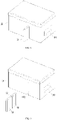
- the present disclosure provides a noise reduction box, which comprises a shell 10 and a detection assembly, wherein the inside of the shell 10 defines a cavity, the shell 10 is provided with an air inlet 101 and an air outlet 102 that are in communication with the cavity; and the detection assembly is mounted on the shell 10 to detect the degree to which the inside of the cavity is dirty.
- a detection assembly is mounted, specifically for detecting the degree to which the inside of the noise reduction box is dirty, on the noise reduction box in the present disclosure, so that the degree to which the inside of the noise reduction box is dirty can be clearly observed by means of the detection assembly, without it being necessary to disassemble the noise reduction box, and same is simple to operate and convenient for checking.
- the above-mentioned detection assembly may be implemented in various ways, as long as it can detect the degree to which the inside of the cavity is dirty and is convenient for the user to observe or learn about the degree to which the inside of the cavity is dirty.
- the detection assembly comprises a dirt adsorption component.
- the above-mentioned dirt adsorption component may be understood as a component that can absorb the pollutants in the air in the cavity and develop the color to different degrees according to the amount of the absorbed pollutants.
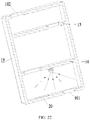
- the dirt adsorption component may be a transparent wall 20, which is formed as a part of the shell 10. By providing the transparent wall 20, dirt will adhere to and accumulate on the transparent wall 20 as the noise reduction box is used, and the transparency of the transparent wall 20 will change accordingly. The higher the degree of the dirtiness is inside the cavity, the lower the transparency of the transparent wall 20 is.
- the degree of dirtiness inside the noise reduction box may be judged according to the level of transparency of the transparent wall 20, thus the degree of the dirtiness inside the noise reduction box can be identified easily without disassembling the noise reduction box, and it is convenient for the user to decide whether to clean and service the noise reduction box.
- the detection assembly may further comprise a light source 21, which may be arranged in the cavity to illuminate the transparent wall 20. By providing the light source 21, the level of transparency of the transparent wall 20 can be clearly observed in all cases, so that the degree of dirtiness inside the cavity can be ascertained more accurately.
- a partition assembly may be arranged inside the cavity to divide the cavity into an air intake cavity 11, a fan mounting cavity 12 and an air discharge cavity 13, wherein the air inlet 101 is in communication with the air intake cavity 11, the air outlet 102 is in communication with the air discharge cavity 13, the air intake cavity 11 is in communication with the fan mounting cavity 12 through a first through hole 141 formed in the partition assembly, and the fan mounting cavity 12 is in communication with the air discharge cavity 13 through a second through hole 151 formed in the partition assembly.
- the air intake cavity 11 may be the cavity that can best represent the degree of dirtiness in the cavity. Therefore, in order to ensure the accuracy of the detection of the degree of dirtiness, a light source 21 may be arranged in the air intake cavity 11, and the transparent wall 20 is formed as a part of the shell 10 for defining the air intake cavity 11.
- the air intake cavity 11 may be defined by the transparent wall 20 in entirety or in part.
- the transparent wall 20 may be arranged on the shell 10 in any way, but it is advantageous to ensure that there is no clearance between the transparent wall 20 and the shell 10, so as to avoid the loss of the gas in the cavity through the clearance.
- the above-mentioned air intake cavity 11, fan mounting cavity 12 and air discharge cavity 13 may be arranged appropriately in any way.
- the air inlet 101 and the air outlet 102 are respectively located in the opposite side walls of the shell 10, and the partition assembly divides the cavity into an air intake cavity 11, a fan mounting cavity 12 and an air discharge cavity 13 sequentially in a direction from the air inlet 101 to the air outlet 102.
- the partition assembly may have any suitable composition and structure.
- the partition assembly may comprise a first partition 14 and a second partition 15 that are spaced apart from each other, wherein the first partition 14 is located between the air intake cavity 11 and the fan mounting cavity 12; the first through hole 141 is arranged in the first partition 14; the second partition 15 is located between the fan mounting cavity 12 and the air discharge cavity 13; and the second through hole 151 is arranged in the second partition 15. It can be understood that the air intake cavity 11 and the fan mounting cavity 12 are separated by the first partition 14, and the fan mounting cavity 12 and the air discharge cavity 13 are separated by the second partition 15.
- the shape and arrangement of the first partition 14 and the second partition 15 may be designed according to the actual requirements of the cavities (i.e., the air intake cavity 11, the fan mounting cavity 12 and the air discharge cavity 13).
- the design of the internal space of the cavity is not limited to the above-mentioned design; instead, the internal space of the cavity may be designed differently according to the actual requirements.
- the transparent wall 20 may be located on a side wall of the shell 10 opposite to the first partition 14, and the light source 21 may be mounted on the first partition 14.
- the light source 21 may be mounted on the first partition 14 in any appropriate way.
- a mounting base 142 for mounting the light source 21 may be provided on the first partition 14.
- the light source 21 may be a columnar lamp bead
- the mounting base 142 may be an annular structure extending from the first partition 14 toward the side where the transparent wall 20 is located, and the light source 21 is embedded in the annular structure.
- the light source 21 may be further connected to the mounting base 142 by bonding, etc., so as to improve the firmness and reliability of the mounting of the light source 21.
- the dirt adsorption component may be air-permeable cotton 30, which is at least partially arranged in the cavity and can be taken out from the cavity.
- the air-permeable cotton 30 is preferably in a light color, such as white, cream, light pink, etc.
- a gradient color bar chart may be worked out according to the degree of dirtiness.
- the mounting component 31 may be taken out from the mounting port 103 at any time to observe the color of the light-colored air-permeable cotton 30 and compare it with the gradient color bar chart to identify the degree of dirtiness, thereby the degree of dirtiness inside the noise reduction box can be judged, so that the user can decide conveniently whether to clean and service the noise reduction box.
- the detection assembly may further comprise a mounting component 31 for mounting the air-permeable cotton 30. That is to say, the air-permeable cotton 30 may be mounted on the mounting component 31 and then mounted on the shell 10 via the mounting component 31.
- the shell 10 may be provided with a mounting port 103 in communication with the cavity, and the mounting component 31 may be removably mounted in the mounting port 103.
- the mounting component 31 When the mounting component 31 is mounted in the mounting port 103, the air-permeable cotton 30 may be positioned in the cavity to detect the degree of dirtiness. To check the degree of dirtiness inside the cavity, the mounting component 31 may be removed from the mounting port 103 and the developed color of the air-permeable cotton 30 may be observed.
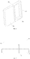
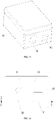
- the mounting component 31 may be a plate-shaped component partially inserted into the cavity through the mounting port 103 (see Figs. 1 and 10 ), and an annular groove 311 is arranged on the mounting component 31 around the periphery of the mounting component 31 and divides the mounting component 31 into an insertion portion 312 and a mounting portion 313 in an insertion direction (i.e., the direction in which the mounting port 103 is arranged) (see Figs. 6 and 12 ), the air-permeable cotton 30 is mounted on the mounting portion 313 (see Figs.
- the detection assembly may further comprise a seal ring 32 embedded in the annular groove 311 and configured to be in seal-fit with the periphery of the mounting port 103 when the mounting portion 313 is inserted into the cavity (see Fig. 2 , 9 , 11 and 16 ).
- the seal ring 32 may be connected to the annular groove 311 by secondary encapsulation or bonding.
- the mounting component 31 and the air-permeable cotton 30 mounted thereon may be inserted into the mounting port 103 and taken out from the mounting port 103 as an integral piece, wherein the insertion portion 312 of the mounting component 31 provides a force applying part for the user to insert the mounting component 31 into the mounting port 103 or extract the mounting component 31 from the mounting port 103 by holding the insertion portion 312 of the mounting component 31; when the mounting component 31 is inserted into the mounting port 103, the mounting portion 313 with the air-permeable cotton 30 enters into the cavity, while the insertion portion 312 is located outside the mounting port 103, and the seal ring 32 between the mounting portion 313 and the insertion portion 312 is in seal-fit with the periphery of the mounting port 103, so as to prevent the loss of the air in the cavity.
- the mounting component 31 may be formed as a square plate-shaped component, and the annular groove 311 divides the mounting component 31 into an insertion portion 312 and a mounting portion 313 in a lengthwise direction.
- the air-permeable cotton 30 may be plate-shaped.
- the mounting portion 313 may be arranged to be inserted into the cavity through the mounting port 103 in a direction perpendicular to the direction of the air flow through the cavity (i.e., the vertical direction shown in Fig. 1 , wherein the air flow direction is horizontal, i.e., a direction from the air inlet 101 to the air outlet 102), and the mounting portion 313 is formed as an annular mounting frame, the air-permeable cotton 30 is embedded in the annular mounting frame, and the gas in the cavity can flow through the air-permeable cotton 30. As shown in Figs.
- annular boss 314 may be provided on an inner peripheral surface of the mounting frame, and the edges of the air-permeable cotton 30 may be bonded to the annular boss 314.
- the air-permeable cotton 30 may be formed integrally with the mounting portion 313 by insert molding.
- the mounting portion 313 may be arranged to be inserted into the cavity through the mounting port 103 in a direction parallel to the direction of the air flow through the cavity (i.e., the horizontal direction shown in Fig. 14 ), and the top surface of the mounting portion 313 is provided with a mounting groove 315 for embedding the air-permeable cotton 30.
- the air-permeable cotton 30 may be bonded to a bottom surface of the mounting groove 315.
- the air-permeable cotton 30 and the mounting portion 313 may be mounted and connected in different ways, not limited to the way described above.
- the air-permeable cotton 30 may be detachably connected with the mounting portion 313, for example, by means of a snap-in structure, so that the air-permeable cotton 30 may be replaced conveniently.
- a guide structure 111 for guiding the insertion of the mounting portion 313 and supporting the mounting portion 313 may be arranged in the cavity.
- the guide structure 111 may be formed as a frame, and the inner peripheral surface of the frame may be provided with guide grooves that match the mounting portion 313 of the mounting component 31. After the mounting portion 313 enters into the mounting port 103, a top edge and a bottom edge of the mounting portion 313 enter into top guide groove and bottom guide groove of the frame and move further along the top guide groove and bottom guide groove.
- a right edge of the mounting portion 313 enters into a right guide groove of the frame and stops the movement; at that point, the seal ring 32 on the mounting portion 31 is right in seal-fit with the periphery of the mounting port 103, and the mounting portion 313 entering into the cavity will not sway under a limiting effect of the guide grooves.
- the guide structure 111 may be formed as two guide rails that are parallel to each other, spaced apart from each other, and extend in the insertion direction of the mounting component 31.
- the mounting portion 313 of the mounting component 31 can move along the guide rails, and the spacing between the guide rails and the bottom wall of the shell 10 may match the thickness of the mounting portion 313, so that the mounting portion 313 can be positioned between the guide rails and the shell 10 and thereby a limiting effect is achieved; in addition, a limiting structure for limiting the further movement of the mounting portion 313 may be arranged on the guide rails or on the bottom wall of the shell 10, so as to limit the insertion position of the mounting portion 313 and ensure the seal-fit between the seal ring 32 and the mounting port 103.
- the structures of the air-permeable cotton 30 and the mounting portion 31, the mounting method for the air-permeable cotton 30 and the mounting portion 31, and the mounting method for the mounting portion 31 and the shell 10 in the present disclosure are not limited to those in the embodiments described above. Any structure and mounting method may be used as long as they can achieve the desired function. However, any such structure and mounting method shall be deemed as falling in the scope of protection of the present disclosure.
- the mounting port 103 may be configured to be in communication with the air intake cavity 11.
- the cavity may be divided by the partition assembly in any appropriate way.
- the inside of the cavity may be designed in other ways to realize the detection of the degree of dirtiness in the cavity and the communication between the cavities more reasonably and advantageously.
- the partition assembly comprises a first partition 14, a second partition 15, a third partition 16 and fourth partitions 17, wherein the first partition 14 and the second partition 15 are spaced apart from each other and divide the cavity into an air intake cavity 11, a fan mounting cavity 12 and an air discharge cavity 13 sequentially in the air flow direction;
- the first partition 14 is provided with a first through hole 141 for communication between the air intake cavity 11 and the fan mounting cavity 12;
- the second partition 15 is provided with a second through hole 151 for communication between the fan mounting cavity 12 and the air discharge cavity 13;
- the third partition 16 and the fourth partitions 17 are arranged in the air intake cavity 11;
- the third partition 16 and the first partition 14 are spaced apart from each other;
- two fourth partitions 17 are connected in a spaced apart manner between the third partition 16 and the first partition 14 so as to divide the air intake cavity 11 into two small cavities that are spaced apart from each other in a left-right direction;
- the first partition 14 is provided with two first through holes 141 that are in communication
- the mounting portion 313 of the mounting component 31 may be located at one of the first through holes 141.
- the gas entering into the air intake cavity 11 through the air inlet 101 may flow into the upper small cavity and the lower small cavity respectively, the gas flowing into the upper small cavity may directly enter into the fan mounting cavity 12 through the upper first through hole 141, while the gas flowing into the lower small cavity may pass through the air-permeable cotton 30 and enter into the fan mounting cavity 12 through the lower first through hole 141.
- a part of the gas may be introduced specially for the detection of the degree of dirtiness on a premise of ensuring gas circulation, so that the detection of the degree of dirtiness is more accurate and reliable.
- the shell 10 may have any appropriate structure, and there is no restriction on the specific structure of the shell 10 in the present disclosure.
- the shell 10 may comprise an upper shell 18 and a lower shell 19, which may be fixedly connected, detachably connected or rotatably connected with each other.
- the noise reduction box may further comprise a sealing element 40 sandwiched between the upper shell 18 and the lower shell 19 to ensure the sealing between the upper shell 18 and the lower shell 19.
- the detection assembly may be mounted on the upper shell 18 or the low shell 19.
- the cavity is mainly defined by the lower shell 19; thus, the detection assembly may be mounted on the lower shell 19.
- the present disclosure provides a ventilation therapeutic device, which comprises the noise reduction box described above.
- the ventilation therapeutic device may be a ventilator, and a fan may be arranged in the noise reduction box.
Landscapes
- Health & Medical Sciences (AREA)
- General Health & Medical Sciences (AREA)
- Life Sciences & Earth Sciences (AREA)
- Heart & Thoracic Surgery (AREA)
- Hematology (AREA)
- Veterinary Medicine (AREA)
- Public Health (AREA)
- Animal Behavior & Ethology (AREA)
- Biomedical Technology (AREA)
- Anesthesiology (AREA)
- Emergency Medicine (AREA)
- Pulmonology (AREA)
- Engineering & Computer Science (AREA)
- Pathology (AREA)
- Immunology (AREA)
- Physics & Mathematics (AREA)
- Analytical Chemistry (AREA)
- General Physics & Mathematics (AREA)
- Chemical & Material Sciences (AREA)
- Biochemistry (AREA)
- Filtering Of Dispersed Particles In Gases (AREA)
- Disinfection, Sterilisation Or Deodorisation Of Air (AREA)
- Measurement Of The Respiration, Hearing Ability, Form, And Blood Characteristics Of Living Organisms (AREA)
Applications Claiming Priority (2)
| Application Number | Priority Date | Filing Date | Title |
|---|---|---|---|
| CN201910849358.4A CN110711300B (zh) | 2019-09-09 | 2019-09-09 | 减噪盒和通气治疗设备 |
| PCT/CN2020/113861 WO2021047486A1 (fr) | 2019-09-09 | 2020-09-08 | Boîte de réduction de bruit et dispositif thérapeutique de ventilation |
Publications (3)
| Publication Number | Publication Date |
|---|---|
| EP4029552A1 true EP4029552A1 (fr) | 2022-07-20 |
| EP4029552A4 EP4029552A4 (fr) | 2022-11-09 |
| EP4029552B1 EP4029552B1 (fr) | 2025-04-16 |
Family
ID=69209742
Family Applications (1)
| Application Number | Title | Priority Date | Filing Date |
|---|---|---|---|
| EP20862748.9A Active EP4029552B1 (fr) | 2019-09-09 | 2020-09-08 | Boîte de réduction de bruit et dispositif thérapeutique de ventilation |
Country Status (4)
| Country | Link |
|---|---|
| US (1) | US20220370741A1 (fr) |
| EP (1) | EP4029552B1 (fr) |
| CN (1) | CN110711300B (fr) |
| WO (1) | WO2021047486A1 (fr) |
Families Citing this family (4)
| Publication number | Priority date | Publication date | Assignee | Title |
|---|---|---|---|---|
| CN110711300B (zh) * | 2019-09-09 | 2023-07-18 | 天津怡和嘉业医疗科技有限公司 | 减噪盒和通气治疗设备 |
| CN114306865A (zh) * | 2021-12-02 | 2022-04-12 | 天津怡和嘉业医疗科技有限公司 | 进气结构、进气部件、减噪盒以及通气治疗设备 |
| CN115252986A (zh) * | 2022-05-20 | 2022-11-01 | 天津怡和嘉业医疗科技有限公司 | 通气组件和通气设备 |
| CN118914479B (zh) * | 2024-10-11 | 2025-01-24 | 南京伊邦电子科技有限公司 | 气体测量装置及方法 |
Family Cites Families (36)
| Publication number | Priority date | Publication date | Assignee | Title |
|---|---|---|---|---|
| JPH0596419U (ja) * | 1991-11-13 | 1993-12-27 | 美八子 坪井 | 車排気清浄器 |
| AU3295897A (en) * | 1996-06-11 | 1998-01-07 | Amway Corporation | Air treatment system |
| EP1878460A4 (fr) * | 2005-05-06 | 2010-06-23 | Teijin Pharma Ltd | Silencieux et dispositif de concentration en oxygene utilisant le silencieux |
| CN101468304B (zh) * | 2007-12-29 | 2012-01-18 | 中国船舶重工集团公司第七一八研究所 | 一种显色甲醛吸附材料的制备方法 |
| CN101850146A (zh) * | 2009-04-01 | 2010-10-06 | 耀信医疗设备顾问股份有限公司 | 呼吸器 |
| US9855397B2 (en) * | 2009-08-11 | 2018-01-02 | Resmed Limited | Sound dampening in positive airway pressure devices |
| SE534962C2 (sv) * | 2010-06-29 | 2012-02-28 | Electrolux Ab | Dammdetekteringssystem för en dammsugare |
| TW201204454A (en) * | 2010-07-20 | 2012-02-01 | Zheng-Xiong Chen | Filter cartridge structure |
| DE202011101554U1 (de) * | 2010-08-11 | 2011-11-16 | Sls Medical Technology Corp., Ltd. | Beatmungsgerät zum Identifizieren der Reinheit/Trübung eines Filters |
| CN102527338A (zh) * | 2011-12-09 | 2012-07-04 | 邯郸派瑞电器有限公司 | 一种显色甲醛吸附材料及其制备方法 |
| JP5987425B2 (ja) * | 2012-04-05 | 2016-09-07 | スズキ株式会社 | 内燃機関の吸気装置 |
| CN104822999A (zh) * | 2012-11-27 | 2015-08-05 | 皇家飞利浦有限公司 | 空气净化装置 |
| EP2968805B1 (fr) * | 2013-03-15 | 2017-12-20 | Human Design Medical, LLC | Appareil de pression positive portatif pour les voies respiratoires et procédé permettant d'atténuer le bruit émis par cet appareil |
| CN203584917U (zh) * | 2013-12-12 | 2014-05-07 | 张晓婷 | 可拆卸式消声器 |
| CN104132003B (zh) * | 2014-07-30 | 2016-08-17 | 邵阳万脉科技有限公司 | 一种正压通气设备的消音装置 |
| WO2016018797A1 (fr) * | 2014-07-31 | 2016-02-04 | Munster Jason | Dispositif personnel de filtration d'air |
| CN104180444A (zh) * | 2014-09-10 | 2014-12-03 | 牛京伟 | 新风一体式空气净化器 |
| CN204132469U (zh) * | 2014-09-16 | 2015-02-04 | 杭州韦尔茂通环境技术有限公司 | 一种含花青素滤材的新型口罩 |
| CN204202038U (zh) * | 2014-10-13 | 2015-03-11 | 小田(中山)实业有限公司 | 一种空气净化器 |
| CN204888796U (zh) * | 2015-06-01 | 2015-12-23 | 天津市四维康环保科技发展有限公司 | 一种带有指示剂的防霾口罩 |
| CN205689989U (zh) * | 2016-06-24 | 2016-11-16 | 北京市泰坦不锈钢厨具有限责任公司 | 消音设备 |
| CN206176561U (zh) * | 2016-06-29 | 2017-05-17 | 王倩 | 一种空气净化机 |
| NL2017108B1 (en) * | 2016-07-05 | 2018-01-12 | Kipp & Zonen B V | Method and device determining soiling of a shield |
| CN206310664U (zh) * | 2016-07-07 | 2017-07-07 | 格林韦尔(北京)科技发展有限公司 | 新风空气净化系统 |
| JP2018122389A (ja) * | 2017-01-31 | 2018-08-09 | 工機ホールディングス株式会社 | 空気圧工具 |
| CN206637817U (zh) * | 2017-04-13 | 2017-11-14 | 黄少纲 | 滤网结构 |
| CN207350551U (zh) * | 2017-10-16 | 2018-05-11 | 深圳金喜来电子股份有限公司 | 一种高效静音空气净化器 |
| CN107860778B (zh) * | 2017-11-20 | 2022-12-13 | 深圳市资福医疗技术有限公司 | 一种胶囊内窥镜脏污检测装置及检测方法 |
| CN207485719U (zh) * | 2017-11-29 | 2018-06-12 | 江西佳通通风设备有限公司 | 可自动清洁柜式离心风机 |
| CN208435355U (zh) * | 2018-02-05 | 2019-01-29 | 佛山市顺德区美的电热电器制造有限公司 | 排气阀结构、锅盖组件及烹饪器具 |
| CN109340944A (zh) * | 2018-10-12 | 2019-02-15 | 东华大学 | 一种空气净化器 |
| CN209265670U (zh) * | 2018-12-17 | 2019-08-16 | 三江侗族自治县古宜镇中心校 | 一种具有灰尘检测功能的智能家居装饰装置 |
| CN109541149B (zh) * | 2018-12-29 | 2023-06-06 | 广东工业大学 | 一种生物型大气重金属污染检测判别装置和应用 |
| CN110711300B (zh) * | 2019-09-09 | 2023-07-18 | 天津怡和嘉业医疗科技有限公司 | 减噪盒和通气治疗设备 |
| CN211132546U (zh) * | 2019-09-09 | 2020-07-31 | 天津怡和嘉业医疗科技有限公司 | 减噪盒和通气治疗设备 |
| CN211884847U (zh) * | 2019-09-09 | 2020-11-10 | 天津怡和嘉业医疗科技有限公司 | 减噪盒和通气治疗设备 |
-
2019
- 2019-09-09 CN CN201910849358.4A patent/CN110711300B/zh active Active
-
2020
- 2020-09-08 EP EP20862748.9A patent/EP4029552B1/fr active Active
- 2020-09-08 US US17/753,634 patent/US20220370741A1/en not_active Abandoned
- 2020-09-08 WO PCT/CN2020/113861 patent/WO2021047486A1/fr not_active Ceased
Also Published As
| Publication number | Publication date |
|---|---|
| EP4029552B1 (fr) | 2025-04-16 |
| CN110711300B (zh) | 2023-07-18 |
| EP4029552A4 (fr) | 2022-11-09 |
| US20220370741A1 (en) | 2022-11-24 |
| CN110711300A (zh) | 2020-01-21 |
| WO2021047486A1 (fr) | 2021-03-18 |
Similar Documents
| Publication | Publication Date | Title |
|---|---|---|
| EP4029552A1 (fr) | Boîte de réduction de bruit et dispositif thérapeutique de ventilation | |
| US11666787B2 (en) | Mask apparatus | |
| CN203550108U (zh) | 气流交换装置 | |
| CN110582317B (zh) | 具有差压传感器的用于呼吸的设备 | |
| US20120037160A1 (en) | Respirator and method of identifying cleanliness/turbidity of filter thereof | |
| DE502007002149D1 (de) | Luftdurchtrittsvorrichtung | |
| CN107995876A (zh) | 空气净化器 | |
| JPWO2010095237A1 (ja) | 熱交換換気装置 | |
| CN104515241A (zh) | 气流交换装置 | |
| EP4434566A2 (fr) | Structure de montage de réservoir d'eau pour appareil de traitement de ventilation et appareil de traitement de ventilation | |
| KR101962940B1 (ko) | 환기장치 | |
| KR101538367B1 (ko) | 환기형 밀폐 시약대를 가지는 실험 테이블 | |
| JP6854397B2 (ja) | 送風機及び送風機に用いられる防塵フィルター | |
| CN104075389A (zh) | 带加湿功能的空气净化装置 | |
| CN211884847U (zh) | 减噪盒和通气治疗设备 | |
| KR102206326B1 (ko) | 가습형 공기 청정기 | |
| CN104740946B (zh) | 一种空气过滤器 | |
| TWM473257U (zh) | 具負壓氣室之生物安全櫃 | |
| CN101346615A (zh) | 风扇吸气传感器 | |
| CN211132546U (zh) | 减噪盒和通气治疗设备 | |
| RU125471U1 (ru) | Рециркулятор воздуха | |
| CN209347874U (zh) | 加湿组件及通气治疗设备 | |
| JP2019060552A (ja) | 熱交換形換気装置 | |
| CN218853345U (zh) | 具有高压电场灭菌模块的穿戴式空气净化装置 | |
| KR102858444B1 (ko) | 비말 전파 방지 장치 |
Legal Events
| Date | Code | Title | Description |
|---|---|---|---|
| STAA | Information on the status of an ep patent application or granted ep patent |
Free format text: STATUS: THE INTERNATIONAL PUBLICATION HAS BEEN MADE |
|
| PUAI | Public reference made under article 153(3) epc to a published international application that has entered the european phase |
Free format text: ORIGINAL CODE: 0009012 |
|
| STAA | Information on the status of an ep patent application or granted ep patent |
Free format text: STATUS: REQUEST FOR EXAMINATION WAS MADE |
|
| 17P | Request for examination filed |
Effective date: 20220404 |
|
| AK | Designated contracting states |
Kind code of ref document: A1 Designated state(s): AL AT BE BG CH CY CZ DE DK EE ES FI FR GB GR HR HU IE IS IT LI LT LU LV MC MK MT NL NO PL PT RO RS SE SI SK SM TR |
|
| A4 | Supplementary search report drawn up and despatched |
Effective date: 20221011 |
|
| RIC1 | Information provided on ipc code assigned before grant |
Ipc: F16L 55/02 20060101ALI20221005BHEP Ipc: G10K 11/16 20060101ALI20221005BHEP Ipc: A61M 16/00 20060101AFI20221005BHEP |
|
| DAV | Request for validation of the european patent (deleted) | ||
| DAX | Request for extension of the european patent (deleted) | ||
| STAA | Information on the status of an ep patent application or granted ep patent |
Free format text: STATUS: EXAMINATION IS IN PROGRESS |
|
| 17Q | First examination report despatched |
Effective date: 20230901 |
|
| GRAP | Despatch of communication of intention to grant a patent |
Free format text: ORIGINAL CODE: EPIDOSNIGR1 |
|
| STAA | Information on the status of an ep patent application or granted ep patent |
Free format text: STATUS: GRANT OF PATENT IS INTENDED |
|
| INTG | Intention to grant announced |
Effective date: 20241202 |
|
| GRAS | Grant fee paid |
Free format text: ORIGINAL CODE: EPIDOSNIGR3 |
|
| GRAA | (expected) grant |
Free format text: ORIGINAL CODE: 0009210 |
|
| STAA | Information on the status of an ep patent application or granted ep patent |
Free format text: STATUS: THE PATENT HAS BEEN GRANTED |
|
| AK | Designated contracting states |
Kind code of ref document: B1 Designated state(s): AL AT BE BG CH CY CZ DE DK EE ES FI FR GB GR HR HU IE IS IT LI LT LU LV MC MK MT NL NO PL PT RO RS SE SI SK SM TR |
|
| REG | Reference to a national code |
Ref country code: GB Ref legal event code: FG4D |
|
| REG | Reference to a national code |
Ref country code: CH Ref legal event code: EP Ref country code: DE Ref legal event code: R096 Ref document number: 602020049694 Country of ref document: DE |
|
| REG | Reference to a national code |
Ref country code: IE Ref legal event code: FG4D |
|
| REG | Reference to a national code |
Ref country code: NL Ref legal event code: MP Effective date: 20250416 |
|
| PG25 | Lapsed in a contracting state [announced via postgrant information from national office to epo] |
Ref country code: NL Free format text: LAPSE BECAUSE OF FAILURE TO SUBMIT A TRANSLATION OF THE DESCRIPTION OR TO PAY THE FEE WITHIN THE PRESCRIBED TIME-LIMIT Effective date: 20250416 |
|
| REG | Reference to a national code |
Ref country code: AT Ref legal event code: MK05 Ref document number: 1785132 Country of ref document: AT Kind code of ref document: T Effective date: 20250416 |
|
| PG25 | Lapsed in a contracting state [announced via postgrant information from national office to epo] |
Ref country code: FI Free format text: LAPSE BECAUSE OF FAILURE TO SUBMIT A TRANSLATION OF THE DESCRIPTION OR TO PAY THE FEE WITHIN THE PRESCRIBED TIME-LIMIT Effective date: 20250416 Ref country code: ES Free format text: LAPSE BECAUSE OF FAILURE TO SUBMIT A TRANSLATION OF THE DESCRIPTION OR TO PAY THE FEE WITHIN THE PRESCRIBED TIME-LIMIT Effective date: 20250416 Ref country code: PT Free format text: LAPSE BECAUSE OF FAILURE TO SUBMIT A TRANSLATION OF THE DESCRIPTION OR TO PAY THE FEE WITHIN THE PRESCRIBED TIME-LIMIT Effective date: 20250818 |
|
| REG | Reference to a national code |
Ref country code: LT Ref legal event code: MG9D |
|
| PG25 | Lapsed in a contracting state [announced via postgrant information from national office to epo] |
Ref country code: NO Free format text: LAPSE BECAUSE OF FAILURE TO SUBMIT A TRANSLATION OF THE DESCRIPTION OR TO PAY THE FEE WITHIN THE PRESCRIBED TIME-LIMIT Effective date: 20250716 Ref country code: GR Free format text: LAPSE BECAUSE OF FAILURE TO SUBMIT A TRANSLATION OF THE DESCRIPTION OR TO PAY THE FEE WITHIN THE PRESCRIBED TIME-LIMIT Effective date: 20250717 |
|
| PG25 | Lapsed in a contracting state [announced via postgrant information from national office to epo] |
Ref country code: PL Free format text: LAPSE BECAUSE OF FAILURE TO SUBMIT A TRANSLATION OF THE DESCRIPTION OR TO PAY THE FEE WITHIN THE PRESCRIBED TIME-LIMIT Effective date: 20250416 |
|
| PG25 | Lapsed in a contracting state [announced via postgrant information from national office to epo] |
Ref country code: BG Free format text: LAPSE BECAUSE OF FAILURE TO SUBMIT A TRANSLATION OF THE DESCRIPTION OR TO PAY THE FEE WITHIN THE PRESCRIBED TIME-LIMIT Effective date: 20250416 |
|
| PG25 | Lapsed in a contracting state [announced via postgrant information from national office to epo] |
Ref country code: HR Free format text: LAPSE BECAUSE OF FAILURE TO SUBMIT A TRANSLATION OF THE DESCRIPTION OR TO PAY THE FEE WITHIN THE PRESCRIBED TIME-LIMIT Effective date: 20250416 |
|
| PG25 | Lapsed in a contracting state [announced via postgrant information from national office to epo] |
Ref country code: AT Free format text: LAPSE BECAUSE OF FAILURE TO SUBMIT A TRANSLATION OF THE DESCRIPTION OR TO PAY THE FEE WITHIN THE PRESCRIBED TIME-LIMIT Effective date: 20250416 |
|
| PG25 | Lapsed in a contracting state [announced via postgrant information from national office to epo] |
Ref country code: RS Free format text: LAPSE BECAUSE OF FAILURE TO SUBMIT A TRANSLATION OF THE DESCRIPTION OR TO PAY THE FEE WITHIN THE PRESCRIBED TIME-LIMIT Effective date: 20250716 |
|
| PG25 | Lapsed in a contracting state [announced via postgrant information from national office to epo] |
Ref country code: IS Free format text: LAPSE BECAUSE OF FAILURE TO SUBMIT A TRANSLATION OF THE DESCRIPTION OR TO PAY THE FEE WITHIN THE PRESCRIBED TIME-LIMIT Effective date: 20250816 |
|
| PG25 | Lapsed in a contracting state [announced via postgrant information from national office to epo] |
Ref country code: LV Free format text: LAPSE BECAUSE OF FAILURE TO SUBMIT A TRANSLATION OF THE DESCRIPTION OR TO PAY THE FEE WITHIN THE PRESCRIBED TIME-LIMIT Effective date: 20250416 |
|
| PG25 | Lapsed in a contracting state [announced via postgrant information from national office to epo] |
Ref country code: SM Free format text: LAPSE BECAUSE OF FAILURE TO SUBMIT A TRANSLATION OF THE DESCRIPTION OR TO PAY THE FEE WITHIN THE PRESCRIBED TIME-LIMIT Effective date: 20250416 Ref country code: DK Free format text: LAPSE BECAUSE OF FAILURE TO SUBMIT A TRANSLATION OF THE DESCRIPTION OR TO PAY THE FEE WITHIN THE PRESCRIBED TIME-LIMIT Effective date: 20250416 |
|
| REG | Reference to a national code |
Ref country code: DE Ref legal event code: R097 Ref document number: 602020049694 Country of ref document: DE |
|
| PG25 | Lapsed in a contracting state [announced via postgrant information from national office to epo] |
Ref country code: CZ Free format text: LAPSE BECAUSE OF FAILURE TO SUBMIT A TRANSLATION OF THE DESCRIPTION OR TO PAY THE FEE WITHIN THE PRESCRIBED TIME-LIMIT Effective date: 20250416 |
|
| PG25 | Lapsed in a contracting state [announced via postgrant information from national office to epo] |
Ref country code: EE Free format text: LAPSE BECAUSE OF FAILURE TO SUBMIT A TRANSLATION OF THE DESCRIPTION OR TO PAY THE FEE WITHIN THE PRESCRIBED TIME-LIMIT Effective date: 20250416 |
|
| PG25 | Lapsed in a contracting state [announced via postgrant information from national office to epo] |
Ref country code: RO Free format text: LAPSE BECAUSE OF FAILURE TO SUBMIT A TRANSLATION OF THE DESCRIPTION OR TO PAY THE FEE WITHIN THE PRESCRIBED TIME-LIMIT Effective date: 20250416 Ref country code: SK Free format text: LAPSE BECAUSE OF FAILURE TO SUBMIT A TRANSLATION OF THE DESCRIPTION OR TO PAY THE FEE WITHIN THE PRESCRIBED TIME-LIMIT Effective date: 20250416 |
|
| PG25 | Lapsed in a contracting state [announced via postgrant information from national office to epo] |
Ref country code: IT Free format text: LAPSE BECAUSE OF FAILURE TO SUBMIT A TRANSLATION OF THE DESCRIPTION OR TO PAY THE FEE WITHIN THE PRESCRIBED TIME-LIMIT Effective date: 20250416 |
|
| PLBE | No opposition filed within time limit |
Free format text: ORIGINAL CODE: 0009261 |
|
| STAA | Information on the status of an ep patent application or granted ep patent |
Free format text: STATUS: NO OPPOSITION FILED WITHIN TIME LIMIT |
|
| REG | Reference to a national code |
Ref country code: CH Ref legal event code: L10 Free format text: ST27 STATUS EVENT CODE: U-0-0-L10-L00 (AS PROVIDED BY THE NATIONAL OFFICE) Effective date: 20260225 |
|
| 26N | No opposition filed |
Effective date: 20260119 |
|
| PGFP | Annual fee paid to national office [announced via postgrant information from national office to epo] |
Ref country code: GB Payment date: 20260227 Year of fee payment: 6 |
|
| PGFP | Annual fee paid to national office [announced via postgrant information from national office to epo] |
Ref country code: DE Payment date: 20260320 Year of fee payment: 6 |
|
| PGFP | Annual fee paid to national office [announced via postgrant information from national office to epo] |
Ref country code: FR Payment date: 20260227 Year of fee payment: 6 |
|
| REG | Reference to a national code |
Ref country code: CH Ref legal event code: H13 Free format text: ST27 STATUS EVENT CODE: U-0-0-H10-H13 (AS PROVIDED BY THE NATIONAL OFFICE) Effective date: 20260425 |