EP4029685A1 - Aérostructure composite dotée d'un élément chauffant intégré - Google Patents
Aérostructure composite dotée d'un élément chauffant intégré Download PDFInfo
- Publication number
- EP4029685A1 EP4029685A1 EP22152558.7A EP22152558A EP4029685A1 EP 4029685 A1 EP4029685 A1 EP 4029685A1 EP 22152558 A EP22152558 A EP 22152558A EP 4029685 A1 EP4029685 A1 EP 4029685A1
- Authority
- EP
- European Patent Office
- Prior art keywords
- layer
- thermoplastic
- composite structure
- heated
- heating
- Prior art date
- Legal status (The legal status is an assumption and is not a legal conclusion. Google has not performed a legal analysis and makes no representation as to the accuracy of the status listed.)
- Withdrawn
Links
Images



Classifications
-
- B—PERFORMING OPERATIONS; TRANSPORTING
- B64—AIRCRAFT; AVIATION; COSMONAUTICS
- B64D—EQUIPMENT FOR FITTING IN OR TO AIRCRAFT; FLIGHT SUITS; PARACHUTES; ARRANGEMENT OR MOUNTING OF POWER PLANTS OR PROPULSION TRANSMISSIONS IN AIRCRAFT
- B64D15/00—De-icing or preventing icing on exterior surfaces of aircraft
- B64D15/12—De-icing or preventing icing on exterior surfaces of aircraft by electric heating
-
- B—PERFORMING OPERATIONS; TRANSPORTING
- B29—WORKING OF PLASTICS; WORKING OF SUBSTANCES IN A PLASTIC STATE IN GENERAL
- B29C—SHAPING OR JOINING OF PLASTICS; SHAPING OF MATERIAL IN A PLASTIC STATE, NOT OTHERWISE PROVIDED FOR; AFTER-TREATMENT OF THE SHAPED PRODUCTS, e.g. REPAIRING
- B29C70/00—Shaping composites, i.e. plastics material comprising reinforcements, fillers or preformed parts, e.g. inserts
- B29C70/88—Shaping composites, i.e. plastics material comprising reinforcements, fillers or preformed parts, e.g. inserts characterised primarily by possessing specific properties, e.g. electrically conductive or locally reinforced
- B29C70/882—Shaping composites, i.e. plastics material comprising reinforcements, fillers or preformed parts, e.g. inserts characterised primarily by possessing specific properties, e.g. electrically conductive or locally reinforced partly or totally electrically conductive, e.g. for EMI shielding
-
- B—PERFORMING OPERATIONS; TRANSPORTING
- B32—LAYERED PRODUCTS
- B32B—LAYERED PRODUCTS, i.e. PRODUCTS BUILT-UP OF STRATA OF FLAT OR NON-FLAT, e.g. CELLULAR OR HONEYCOMB, FORM
- B32B27/00—Layered products comprising a layer of synthetic resin
- B32B27/06—Layered products comprising a layer of synthetic resin as the main or only constituent of a layer, which is next to another layer of the same or of a different material
- B32B27/08—Layered products comprising a layer of synthetic resin as the main or only constituent of a layer, which is next to another layer of the same or of a different material of synthetic resin
-
- B—PERFORMING OPERATIONS; TRANSPORTING
- B32—LAYERED PRODUCTS
- B32B—LAYERED PRODUCTS, i.e. PRODUCTS BUILT-UP OF STRATA OF FLAT OR NON-FLAT, e.g. CELLULAR OR HONEYCOMB, FORM
- B32B27/00—Layered products comprising a layer of synthetic resin
- B32B27/28—Layered products comprising a layer of synthetic resin comprising synthetic resins not wholly covered by any one of the sub-groups B32B27/30 - B32B27/42
- B32B27/288—Layered products comprising a layer of synthetic resin comprising synthetic resins not wholly covered by any one of the sub-groups B32B27/30 - B32B27/42 comprising polyketones
-
- B—PERFORMING OPERATIONS; TRANSPORTING
- B32—LAYERED PRODUCTS
- B32B—LAYERED PRODUCTS, i.e. PRODUCTS BUILT-UP OF STRATA OF FLAT OR NON-FLAT, e.g. CELLULAR OR HONEYCOMB, FORM
- B32B7/00—Layered products characterised by the relation between layers; Layered products characterised by the relative orientation of features between layers, or by the relative values of a measurable parameter between layers, i.e. products comprising layers having different physical, chemical or physicochemical properties; Layered products characterised by the interconnection of layers
- B32B7/02—Physical, chemical or physicochemical properties
- B32B7/025—Electric or magnetic properties
-
- B—PERFORMING OPERATIONS; TRANSPORTING
- B64—AIRCRAFT; AVIATION; COSMONAUTICS
- B64D—EQUIPMENT FOR FITTING IN OR TO AIRCRAFT; FLIGHT SUITS; PARACHUTES; ARRANGEMENT OR MOUNTING OF POWER PLANTS OR PROPULSION TRANSMISSIONS IN AIRCRAFT
- B64D15/00—De-icing or preventing icing on exterior surfaces of aircraft
- B64D15/20—Means for detecting icing or initiating de-icing
- B64D15/22—Automatic initiation by icing detector
-
- B—PERFORMING OPERATIONS; TRANSPORTING
- B64—AIRCRAFT; AVIATION; COSMONAUTICS
- B64D—EQUIPMENT FOR FITTING IN OR TO AIRCRAFT; FLIGHT SUITS; PARACHUTES; ARRANGEMENT OR MOUNTING OF POWER PLANTS OR PROPULSION TRANSMISSIONS IN AIRCRAFT
- B64D33/00—Arrangement in aircraft of power plant parts or auxiliaries not otherwise provided for
- B64D33/02—Arrangement in aircraft of power plant parts or auxiliaries not otherwise provided for of combustion air intakes
-
- H—ELECTRICITY
- H05—ELECTRIC TECHNIQUES NOT OTHERWISE PROVIDED FOR
- H05B—ELECTRIC HEATING; ELECTRIC LIGHT SOURCES NOT OTHERWISE PROVIDED FOR; CIRCUIT ARRANGEMENTS FOR ELECTRIC LIGHT SOURCES, IN GENERAL
- H05B3/00—Ohmic-resistance heating
- H05B3/10—Heating elements characterised by the composition or nature of the materials or by the arrangement of the conductor
- H05B3/12—Heating elements characterised by the composition or nature of the materials or by the arrangement of the conductor characterised by the composition or nature of the conductive material
- H05B3/14—Heating elements characterised by the composition or nature of the materials or by the arrangement of the conductor characterised by the composition or nature of the conductive material the material being non-metallic
- H05B3/145—Carbon only, e.g. carbon black, graphite
-
- H—ELECTRICITY
- H05—ELECTRIC TECHNIQUES NOT OTHERWISE PROVIDED FOR
- H05B—ELECTRIC HEATING; ELECTRIC LIGHT SOURCES NOT OTHERWISE PROVIDED FOR; CIRCUIT ARRANGEMENTS FOR ELECTRIC LIGHT SOURCES, IN GENERAL
- H05B3/00—Ohmic-resistance heating
- H05B3/20—Heating elements having extended surface area substantially in a two-dimensional [2D] plane, e.g. plate-heater
- H05B3/22—Heating elements having extended surface area substantially in a two-dimensional [2D] plane, e.g. plate-heater non-flexible
- H05B3/26—Heating elements having extended surface area substantially in a two-dimensional [2D] plane, e.g. plate-heater non-flexible heating conductor mounted on insulating base
-
- H—ELECTRICITY
- H05—ELECTRIC TECHNIQUES NOT OTHERWISE PROVIDED FOR
- H05B—ELECTRIC HEATING; ELECTRIC LIGHT SOURCES NOT OTHERWISE PROVIDED FOR; CIRCUIT ARRANGEMENTS FOR ELECTRIC LIGHT SOURCES, IN GENERAL
- H05B3/00—Ohmic-resistance heating
- H05B3/20—Heating elements having extended surface area substantially in a two-dimensional [2D] plane, e.g. plate-heater
- H05B3/22—Heating elements having extended surface area substantially in a two-dimensional [2D] plane, e.g. plate-heater non-flexible
- H05B3/28—Heating elements having extended surface area substantially in a two-dimensional [2D] plane, e.g. plate-heater non-flexible heating conductor embedded in insulating material
- H05B3/286—Heating elements having extended surface area substantially in a two-dimensional [2D] plane, e.g. plate-heater non-flexible heating conductor embedded in insulating material the insulating material being an organic material, e.g. plastic
-
- B—PERFORMING OPERATIONS; TRANSPORTING
- B29—WORKING OF PLASTICS; WORKING OF SUBSTANCES IN A PLASTIC STATE IN GENERAL
- B29K—INDEXING SCHEME ASSOCIATED WITH SUBCLASSES B29B, B29C OR B29D, RELATING TO MOULDING MATERIALS OR TO MATERIALS FOR MOULDS, REINFORCEMENTS, FILLERS OR PREFORMED PARTS, e.g. INSERTS
- B29K2071/00—Use of polyethers, e.g. PEEK, i.e. polyether-etherketone or PEK, i.e. polyetherketone or derivatives thereof, as moulding material
-
- B—PERFORMING OPERATIONS; TRANSPORTING
- B29—WORKING OF PLASTICS; WORKING OF SUBSTANCES IN A PLASTIC STATE IN GENERAL
- B29K—INDEXING SCHEME ASSOCIATED WITH SUBCLASSES B29B, B29C OR B29D, RELATING TO MOULDING MATERIALS OR TO MATERIALS FOR MOULDS, REINFORCEMENTS, FILLERS OR PREFORMED PARTS, e.g. INSERTS
- B29K2105/00—Condition, form or state of moulded material or of the material to be shaped
- B29K2105/06—Condition, form or state of moulded material or of the material to be shaped containing reinforcements, fillers or inserts
- B29K2105/08—Condition, form or state of moulded material or of the material to be shaped containing reinforcements, fillers or inserts of continuous length, e.g. cords, rovings, mats, fabrics, strands or yarns
- B29K2105/10—Cords, strands or rovings, e.g. oriented cords, strands or rovings
- B29K2105/101—Oriented
-
- B—PERFORMING OPERATIONS; TRANSPORTING
- B29—WORKING OF PLASTICS; WORKING OF SUBSTANCES IN A PLASTIC STATE IN GENERAL
- B29K—INDEXING SCHEME ASSOCIATED WITH SUBCLASSES B29B, B29C OR B29D, RELATING TO MOULDING MATERIALS OR TO MATERIALS FOR MOULDS, REINFORCEMENTS, FILLERS OR PREFORMED PARTS, e.g. INSERTS
- B29K2307/00—Use of elements other than metals as reinforcement
- B29K2307/04—Carbon
-
- B—PERFORMING OPERATIONS; TRANSPORTING
- B29—WORKING OF PLASTICS; WORKING OF SUBSTANCES IN A PLASTIC STATE IN GENERAL
- B29K—INDEXING SCHEME ASSOCIATED WITH SUBCLASSES B29B, B29C OR B29D, RELATING TO MOULDING MATERIALS OR TO MATERIALS FOR MOULDS, REINFORCEMENTS, FILLERS OR PREFORMED PARTS, e.g. INSERTS
- B29K2995/00—Properties of moulding materials, reinforcements, fillers, preformed parts or moulds
- B29K2995/0003—Properties of moulding materials, reinforcements, fillers, preformed parts or moulds having particular electrical or magnetic properties, e.g. piezoelectric
- B29K2995/0005—Conductive
-
- B—PERFORMING OPERATIONS; TRANSPORTING
- B29—WORKING OF PLASTICS; WORKING OF SUBSTANCES IN A PLASTIC STATE IN GENERAL
- B29L—INDEXING SCHEME ASSOCIATED WITH SUBCLASS B29C, RELATING TO PARTICULAR ARTICLES
- B29L2031/00—Other particular articles
- B29L2031/30—Vehicles, e.g. ships or aircraft, or body parts thereof
- B29L2031/3076—Aircrafts
-
- B—PERFORMING OPERATIONS; TRANSPORTING
- B32—LAYERED PRODUCTS
- B32B—LAYERED PRODUCTS, i.e. PRODUCTS BUILT-UP OF STRATA OF FLAT OR NON-FLAT, e.g. CELLULAR OR HONEYCOMB, FORM
- B32B2250/00—Layers arrangement
- B32B2250/03—3 layers
-
- B—PERFORMING OPERATIONS; TRANSPORTING
- B32—LAYERED PRODUCTS
- B32B—LAYERED PRODUCTS, i.e. PRODUCTS BUILT-UP OF STRATA OF FLAT OR NON-FLAT, e.g. CELLULAR OR HONEYCOMB, FORM
- B32B2250/00—Layers arrangement
- B32B2250/05—5 or more layers
-
- B—PERFORMING OPERATIONS; TRANSPORTING
- B32—LAYERED PRODUCTS
- B32B—LAYERED PRODUCTS, i.e. PRODUCTS BUILT-UP OF STRATA OF FLAT OR NON-FLAT, e.g. CELLULAR OR HONEYCOMB, FORM
- B32B2260/00—Layered product comprising an impregnated, embedded, or bonded layer wherein the layer comprises an impregnation, embedding, or binder material
- B32B2260/02—Composition of the impregnated, bonded or embedded layer
- B32B2260/021—Fibrous or filamentary layer
-
- B—PERFORMING OPERATIONS; TRANSPORTING
- B32—LAYERED PRODUCTS
- B32B—LAYERED PRODUCTS, i.e. PRODUCTS BUILT-UP OF STRATA OF FLAT OR NON-FLAT, e.g. CELLULAR OR HONEYCOMB, FORM
- B32B2260/00—Layered product comprising an impregnated, embedded, or bonded layer wherein the layer comprises an impregnation, embedding, or binder material
- B32B2260/04—Impregnation, embedding, or binder material
- B32B2260/046—Synthetic resin
-
- B—PERFORMING OPERATIONS; TRANSPORTING
- B32—LAYERED PRODUCTS
- B32B—LAYERED PRODUCTS, i.e. PRODUCTS BUILT-UP OF STRATA OF FLAT OR NON-FLAT, e.g. CELLULAR OR HONEYCOMB, FORM
- B32B2262/00—Composition or structural features of fibres which form a fibrous or filamentary layer or are present as additives
- B32B2262/10—Inorganic fibres
- B32B2262/106—Carbon fibres, e.g. graphite fibres
-
- B—PERFORMING OPERATIONS; TRANSPORTING
- B32—LAYERED PRODUCTS
- B32B—LAYERED PRODUCTS, i.e. PRODUCTS BUILT-UP OF STRATA OF FLAT OR NON-FLAT, e.g. CELLULAR OR HONEYCOMB, FORM
- B32B2307/00—Properties of the layers or laminate
- B32B2307/20—Properties of the layers or laminate having particular electrical or magnetic properties, e.g. piezoelectric
- B32B2307/202—Conductive
-
- B—PERFORMING OPERATIONS; TRANSPORTING
- B32—LAYERED PRODUCTS
- B32B—LAYERED PRODUCTS, i.e. PRODUCTS BUILT-UP OF STRATA OF FLAT OR NON-FLAT, e.g. CELLULAR OR HONEYCOMB, FORM
- B32B2457/00—Electrical equipment
-
- B—PERFORMING OPERATIONS; TRANSPORTING
- B32—LAYERED PRODUCTS
- B32B—LAYERED PRODUCTS, i.e. PRODUCTS BUILT-UP OF STRATA OF FLAT OR NON-FLAT, e.g. CELLULAR OR HONEYCOMB, FORM
- B32B2605/00—Vehicles
- B32B2605/18—Aircraft
-
- B—PERFORMING OPERATIONS; TRANSPORTING
- B64—AIRCRAFT; AVIATION; COSMONAUTICS
- B64D—EQUIPMENT FOR FITTING IN OR TO AIRCRAFT; FLIGHT SUITS; PARACHUTES; ARRANGEMENT OR MOUNTING OF POWER PLANTS OR PROPULSION TRANSMISSIONS IN AIRCRAFT
- B64D33/00—Arrangement in aircraft of power plant parts or auxiliaries not otherwise provided for
- B64D33/02—Arrangement in aircraft of power plant parts or auxiliaries not otherwise provided for of combustion air intakes
- B64D2033/0233—Arrangement in aircraft of power plant parts or auxiliaries not otherwise provided for of combustion air intakes comprising de-icing means
-
- H—ELECTRICITY
- H05—ELECTRIC TECHNIQUES NOT OTHERWISE PROVIDED FOR
- H05B—ELECTRIC HEATING; ELECTRIC LIGHT SOURCES NOT OTHERWISE PROVIDED FOR; CIRCUIT ARRANGEMENTS FOR ELECTRIC LIGHT SOURCES, IN GENERAL
- H05B2203/00—Aspects relating to Ohmic resistive heating covered by group H05B3/00
- H05B2203/002—Heaters using a particular layout for the resistive material or resistive elements
- H05B2203/003—Heaters using a particular layout for the resistive material or resistive elements using serpentine layout
-
- H—ELECTRICITY
- H05—ELECTRIC TECHNIQUES NOT OTHERWISE PROVIDED FOR
- H05B—ELECTRIC HEATING; ELECTRIC LIGHT SOURCES NOT OTHERWISE PROVIDED FOR; CIRCUIT ARRANGEMENTS FOR ELECTRIC LIGHT SOURCES, IN GENERAL
- H05B2214/00—Aspects relating to resistive heating, induction heating and heating using microwaves, covered by groups H05B3/00, H05B6/00
- H05B2214/02—Heaters specially designed for de-icing or protection against icing
-
- Y—GENERAL TAGGING OF NEW TECHNOLOGICAL DEVELOPMENTS; GENERAL TAGGING OF CROSS-SECTIONAL TECHNOLOGIES SPANNING OVER SEVERAL SECTIONS OF THE IPC; TECHNICAL SUBJECTS COVERED BY FORMER USPC CROSS-REFERENCE ART COLLECTIONS [XRACs] AND DIGESTS
- Y02—TECHNOLOGIES OR APPLICATIONS FOR MITIGATION OR ADAPTATION AGAINST CLIMATE CHANGE
- Y02T—CLIMATE CHANGE MITIGATION TECHNOLOGIES RELATED TO TRANSPORTATION
- Y02T50/00—Aeronautics or air transport
- Y02T50/40—Weight reduction
Definitions
- the present invention relates to the field of composite materials.
- the present application relates to composite materials that incorporate an integrated heating assembly.
- the present invention finds particular application to the field of ice protection systems for composite aerostructures.
- Ice build-up on aircraft surfaces can cause dangerous in flight situations and has led to numerous fatalities over the years.
- icing leads to increased weight, increased drag and decreased lift.
- icing on the leading edge can create flow problems and lead to ice ingestion, which can degrade operation of the engine or damage components of the engine.
- ice protection systems To prevent the dangers associated with icing, numerous ice protection systems have been developed over the years to protect the aircraft from icing and/or to shed ice from the surfaces if ice accumulates.
- the primary ice protection system in use today are bleed air systems that redirects a portion of the compressed air from the engine before the air enters the combustion chamber.
- the compressed air is pressurized hot air that is used to heat up surfaces of the aircraft to prevent the build-up of ice.
- bleed air systems are effective, they reduce the efficiency of the engines and increase the weight of the aircraft. Accordingly, there has been a long felt need for an ice protection system that does not suffer from the drawbacks of the known systems.
- a heated aerostructure includes a composite structure that comprises a carbon fiber reinforced thermoplastic upper layer, a carbon fiber reinforced thermoplastic lower layer and a carbon fiber reinforced thermoplastic heater layer.
- the heater layer includes a plurality of electrically conductive carbon fibers, a first electrode electrically connected with the conductive carbon fibers, and a second electrode electrically connected with the conductive carbon fibers.
- the conductive carbon fibers provide an electrical pathway between the first electrode and the second electrode.
- the aerostructure also includes a controller connected with an electrical power source for controlling the power provided to the first electrode.
- the first electrode and the electrically conductive carbon fibers are connected such that electric power applied to the first electrode is conducted to the electrically conductive carbon fibers to provide resistive heating sufficient to heat the composite structure to impede formation of ice on the composite structure.
- the present invention provides a heated aerostructure having a controller that is operable to control the electrical power provided to the first electrode in response to signals received from a sensor that detects a characteristic indicative of the presence of ice on the aerostructure.
- the present invention provides a heated aerostructure having an upper layer comprises a semicrystalline thermoplastic in the polyaryletherketone family.
- the present invention provides a heated aerostructure having a lower layer that comprises a semicrystalline thermoplastic in the polyaryletherketone family.
- the present invention provides a heated aerostructure wherein the heater layer and at least one of an upper layer and a lower layer comprise similar thermoplastic.
- the present invention provides a heated aerostructure having a heater layer, an upper layer and a lower layer that comprise a semicrystalline thermoplastic in the polyaryletherketone family.
- the present invention provides a heated aerostructure comprising a first electrically insulative layer insulating an upper layer from the heater layer.
- the present invention also provides a heated aerostructure comprising a second electrically insulative layer insulating the lower layer from the heater layer.
- one or both of the first and second electrically insulative layers may comprise thermoplastic.
- the first electrically insulative layer comprises a composite material comprising reinforcing fibers embedded within the thermoplastic.
- the present invention provides a heated aerostructure that includes a first electrode that comprises a metallic mesh embedded within a thermoplastic of a heater layer.
- the present invention provides a heated aerostructure comprising a composite structure that forms a portion of an airfoil.
- the present invention provides a heated aerostructure comprising a composite structure that forms a portion of a nacelle.
- the present invention provides a heated aerostructure having an upper layer comprising a plurality of carbon fiber reinforced thermoplastic lamina.
- the present invention provides a heated aerostructure that may have a lower layer comprises a plurality of carbon fiber reinforced thermoplastic lamina.
- the thermoplastic of each of the heater layer, the upper layer and the lower layer are fused with the thermoplastic in adjacent layers.
- the present invention provides a heated aerostructure that includes a composite structure formed of a reinforced thermoplastic upper layer, a reinforced thermoplastic lower layer, and a reinforced thermoplastic heater layer.
- the heater layer includes a plurality of electrically conductive non-metallic fibers, a first electrode electrically connected with the conductive non-metallic fibers, and a second electrode electrically connected with the conductive non-metallic fibers, so that the conductive non-metallic fibers provide an electrical pathway between the first electrode and the second electrode.
- a sensor detects a characteristic indicative of ice formation on the composite structure and a controller connected with the sensor and an electrical power source controls the power provided to the first electrode.
- the first electrode and the conductive non-metallic fibers are connected such that electric power applied to the first electrode is conducted to the electrically conductive non-metallic fibers to provide resistive heating sufficient to heat the composite structure to impede formation of ice on the composite structure.
- the present invention provides a heated composite structure that includes a carbon fiber reinforced thermoplastic upper layer, a carbon fiber reinforced thermoplastic lower layer, and a carbon fiber reinforced thermoplastic heater layer.
- the heater layer may include a plurality of electrically conductive carbon fibers, a first electrode electrically connected with the conductive carbon fibers, and a second electrode electrically connected with the conductive carbon fibers, so that the conductive carbon fibers provide an electrical pathway between the first electrode and the second electrode.
- the first electrode and the electrically conductive carbon fibers are connected such that electric power applied to the first electrode is conducted to the electrically conductive carbon fibers to provide resistive heating sufficient for the heating layer to achieve a temperature increase of at least 50 degrees Fahrenheit (10 degrees Celsius) or approximately 30 degrees Celsius.
- the carbon fibers of the heater layer are connected with the first electrode such that electric power applied to the first electrode is conducted to the electrically conductive carbon fibers to provide resistive heating sufficient for the heating layer to achieve a temperature increase of 100 degrees Fahrenheit (37.77 degrees Celsius) or approximately 55 degrees Celsius.
- the carbon fibers of the heater layer may be connected with the first electrode such that electric power applied to the first electrode is conducted to the electrically conductive carbon fibers to provide resistive heating sufficient for the heating layer to achieve a temperature increase of 200 degrees Fahrenheit (93.33 degrees Celsius) or approximately 1 10 degrees Celsius.
- the present invention provides a method for forming a heated composite structure.
- the method includes the steps of providing a plurality of carbon fibers embedded within a thermoplastic matrix and electrically connecting the carbon fibers with first and second electrodes to form a heater layer.
- the method further includes the steps of heating the heating layer above the melting temperature of the thermoplastic matrix and heating a plurality of layers of reinforced thermoplastic laminae.
- the thermoplastic in the laminae have a melting temperature and the step of heating the plurality of layers comprises heating the layers above the melting temperature of the thermoplastic in the laminae.
- the method includes the step of applying the heated plurality of layers to the heated heating layer so that the heater is fused with the plurality of layers after the heater layer and the plurality of layers cool.
- the present invention provides a method of heating a composite structure.
- the method includes the step of providing a composite structure formed of a carbon fiber reinforced thermoplastic layer, wherein the carbon fibers are connected with first and second electrodes.
- the first and second electrodes are connected to an electric source and the flow of electricity from the electric source to the first electrode is controlled so that the electricity flows from the first electrode to the carbon fibers to the second electrode to provide resistive heating sufficient to heat the composite structure.
- the present invention provides a method of heating a composite structure wherein the step of controlling comprises controlling the flow of electricity to provide resistive heating sufficient to heat the composite structure to impede formation of ice on the composite structure.
- the present invention provides a method that include the step of monitoring the temperature of the composite structure and a step of controlling comprises controlling the flow of electricity in response to the step of monitoring.
- the present invention provides a heated composite structure that includes a carbon fiber reinforced thermoplastic upper layer, a carbon fiber reinforced thermoplastic lower layer, and a carbon fiber reinforced thermoplastic heater layer.
- the upper layer, lower layer and heater layer are consolidated to form a laminate.
- the heater layer comprises a plurality of electrically conductive carbon fibers and the heater layer is configured so that the electrically conductive carbon fibers of the heater layer are connectable with a power source so that electricity can flow through the electrically conductive carbon fibers of the heater layer to provide resistive heating sufficient for the heating layer to heat at least a portion of the laminate at least approximately 50 degrees Fahrenheit (10 degrees Celsius) or 30 degrees Celsius.
- the structure includes a sensor operable to sense a characteristic indicative of ice forming on an outer surface of the laminate.
- the structure may optionally include a controller connected with the sensor and an electrical power source for controlling the power provided to the heater layer.
- the structure may optionally include first and second electrodes embedded within the laminate in electrical contract with the electrically conductive carbon fibers such that electric power applied to the first electrode is conducted to the electrically conductive carbon fibers to provide resistive heating sufficient to heat the composite structure to impede formation of ice on the composite structure.
- the controller may be operable to control the electrical power provided to heater layer in response to signals received from the sensor.
- a system that incorporates a composite structure with an integrated heating assembly is designated generally 10.
- the system includes a laminate 20, a power source 60 and a controller 70 that controls the power provided to the laminate.
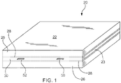
- the laminate includes structural layers 25, 26 and a heating assembly 30.
- the heating layer 30 may be configured to provide sufficient heat to the structure to heat the upper and/or lower surface of the laminate 20.
- the laminate 20 includes a heating element 30 embedded within structural layers.
- the heating element 30 is sandwiched between an upper structural layer 25 and a lower structural layer 26.
- the upper and lower structural layers 25, 26 are each formed of one or more plies of a composite lamina.
- each structural layer comprises a plurality of composite laminae.
- Each composite lamina comprises reinforcing elements embedded within a matrix material.
- the reinforcing elements may be any of a variety of reinforcing materials.
- the reinforcing elements may be elongated strands or fibers of glass or carbon.
- an exemplary carbon fiber is a continuous, high strength, high strain, PAN based fiber in tows of 3,000 to 12,000.
- the reinforcing elements are carbon fibers produced by Hexcel Corporation of Stamford, CT and sold under the name HEXTOW, such as HEXTOW AS4D. These reinforcing fibers may be treated with a surface treatment and may be sized to improve their interlaminar shear properties with the matrix material.
- these materials are intended as exemplary materials; other materials can be utilized depending on the environment in which the laminate is to be used.
- the reinforcing elements are embedded within a matrix material, such as a polymer.
- a matrix material such as a polymer.
- the matrix material is a thermoplastic material, such as a thermoplastic elastomer. More specifically, the thermoplastic material is a semi-crystalline thermoplastic.
- the thermoplastic may be a thermoplastic polymer in the polyaryletherketone (PAEK) family, including, but not limited to polyetheretherketone (PEEK) and polyetherketoneketone (PEKK).
- the structural layers 25, 26 are formed of one or more composite laminae, which may be carbon fiber reinforced thermoplastic composites.
- the lamina may be thermoplastic prepregs, which are laminae in which the reinforcement materials have been pre-impregnated with resin.
- the prepreg may be thermoplastic prepregs produced by coating fiber reinforcement with a thermoplastic matrix.
- Such a prepreg lamina has the ability to be reheated and reformed by heating the lamina above the melting point of the thermoplastic matrix.
- exemplary prepreg materials that may be used to form the structural elements 25, 26 include, but are not limited to, materials produced by TenCate Advanced Composites USA of Morgan Hill, California and sold under the name CETEX, such as TC1200, TC1225 and TC1320.
- TC1200 is a carbon fiber reinforced semi-crystalline PEEK composite having a glass transition temperature (Tg) of 143 °C / 289 °F and a melting temperature (Tm) of 343 °C / 649 °F.
- TC1225 is a carbon fiber reinforced semi-crystalline PAEK composite having a Tgof 147 °C / 297 °F and a Tmof 305 °C / 581 °F.
- TC1320 is a carbon fiber reinforced semicrystalline PEKK composite having a Tgof 150 °C / 318 °F and a Tmof 337 °C / 639 °F.
- the laminate comprises a heating layer 30 disposed between the upper and lower structural layers 25, 26.
- the structural layers are formed of composite lamina and are configured to carry the structural load.
- the heating layer may be configured to carry structural load, in the present instance, the heater layer 30 is configured to heat the laminate 20 without carrying significant, if any, structural load.
- the heating layer 30 is configured to provide sufficient heat to raise the temperature of the upper surface 22 and/or the lower surface 23 of the laminate.
- the heating layer 30 is configured to provide resistive heating by passing current through one or more resistive elements 40, which operate as the heating element.
- the resistive elements 40 are electrically conductive, but provide sufficient electrical resistance to provide resistive heating when current is applied.
- a variety of resistive elements may be incorporated into the heating layer 30, however, in the present instance, the resistive elements are formed of a non-metallic element.
- the heating element may be the same or substantially similar to the reinforcing elements in one or both of the structural layers 25, 26.
- the resistive elements 40 are carbon fibers.
- the resistive elements 40 are carbon fibers, such as the continuous, high strength, high strain, PAN based fibers described above in connection with the structural layers 25, 26.
- the resistive elements 40 are connected with an input electrode 50 and an output electrode 52.
- the resistive elements 40 provide a continuous path between the first and second electrodes 50, 52.
- the resistive elements 40 are oriented in the laminate 20 to heat at least a portion of the laminate along the length of the laminate.
- the resistive elements 40 are carbon fibers and the fibers are oriented to form a serpentine pattern through the length of the laminate.
- each resistive element may extend the length and/or width of the laminate, in the present instance, the resistive elements extend a portion of the length of the laminate.
- a first resistive element 40a has a first end 42a connected with the first electrode 50 and a second end 44a connected with the second electrode 52.
- additional resistive elements 40b, 40c extend between electrodes 50, 52.
- each resistive element 40a, 40b, 40c is described as an individual element, however, it should be understood that each resistive element may comprise a plurality of separate resistive elements.
- each resistive element may comprise hundreds or thousands of individual strands or fibers that extend along the length of the resistive element.
- the carbon fiber resistive elements 40 are embedded within a matrix material.
- the matrix material is a thermoplastic material that can be heat fused with the other layers in the laminate. By heat fusing the matrix material of the heating layer, the heating layer is integrally formed with the laminate.
- the heating assembly is formed of a composite material that is substantially similar to the composite material forming the structural layers 25, 26.
- the resistive elements are carbon fibers and the matrix material is a thermoplastic material, such as a semi-crystalline thermoplastic in the polyaryletherketone (PAEK) family.
- PAEK polyaryletherketone
- the resistive elements are formed from a lamina of unidirectional carbon fiber material.
- the unidirectional fibers are formed into a plurality of segments that are interconnected to form continuous resistive elements from the first end 42 to the second end 44.
- the individual segments of each resistive element are interconnected by conductive elements, such as copper.
- the resistive element may be formed of a plurality of continuous strands or fibers of conductive material.
- the resistive element may comprise a plurality of continuous carbon fibers in which the carbon fibers are not straight, but instead form curved elements, similar to the serpentine pattern shown in Fig. 2 .
- the carbon fibers may be formed in a wavy composite in which the fibers are laid out in a periodic wave pattern, similar to a sine wave.
- the carbon fibers may be coated with a sizing material to improve the bonding between the carbon fibers and the matrix material.
- the sizing material may tend to electrically insulate the carbon fibers from making electrical connection with the electrodes 50, 52.
- the electrodes 50, 52 comprise a conductive metal mesh, such as copper mesh. The metal mesh provides multiple points of contact along the length of the end of each resistive element 40.
- the configuration of the copper mesh may vary, however, preferably the mesh is configured so that the open portion of the mesh (the area of pores per square inch/cm of mesh) is greater than the closed portion of the mesh (i.e. the area of the copper per square inch/cm of mesh). Additionally, the open portion of the mesh may be greater than approximately 60%. In some configurations, the open portion of the mesh may be greater than approximately 70%.
- the heating layer 30 comprises a plurality of carbon fibers electrically connected with conductive elements, such as the input electrode 50 and the output electrode 52.
- the carbon fibers are embedded within a matrix material, such as a thermoplastic.
- the structural layers 25, 26 may also be formed of carbon fiber reinforced thermoplastic material. Therefore, the carbon fibers in the structural elements are also electrical conductive.
- the laminate may include an insulative layer. The insulative layer 28 is disposed between the heating layer 30 and the structural layers.
- the laminate may include a first insulation layer 28 between the upper face of the heating layer 30 and the upper structural layer 25 and a second insulation layer 28 between the lower face of the heating layer and the lower structural layer 26.
- the insulation layer 28 provides electrical insulation between the structural layers and the electrically conductive elements (e.g. resistive elements 40, input electrode 50, output electrode 52) of the heating layer 30.
- the insulation layer 28 may comprise any of a variety of electrically insulative materials.
- the insulation layer 28 comprises a thermoplastic material.
- the insulation layer comprises one or more lamina of glass reinforced thermoplastic.
- each of the structural layers 25, 26, the heating layer 30 and the insulative layers 28 may comprise layers of reinforced thermoplastic composite materials. Accordingly, the upper structural layer 25, the lower structural layers, the heating layer and any insulation layer can be integrally connected by fusing the layers. Specifically, the layers may be consolidated by applying sufficient heat to raise the layers above the melting point of the thermoplastic matrix and applying sufficient pressure to fuse the layers together. In this way, the heating layer 30 is embedded within the laminate between the upper and lower structural layers 25, 26.
- the heating layer 30 is depicted as having a thickness greater than the insulation layers 28.
- the heating layer 30 may be just a single lamina of composite material.
- the insulation layer may be a single lamina of composite material.
- each insulation layer 28 may comprises one or more lamina.
- the thickness of the structural layers may be significantly thicker than the thickness of the thickness of the heating layer.
- the upper layer 25 may be formed from three or more laminae of reinforced composite material so that the structural layers are substantially thicker than the thickness of the heating layer.
- the heating layer 30 is not necessarily a continuous layer extending the entire length and width of the laminate as shown in Fig. 1 . Instead, the heating layer 30 may be embedded within the insulation layers 28.
- the heated laminate 20 described above may be incorporated into a system for providing controlled heating.
- the system incorporates a power source 60 that is connected to heated laminate 20 via a controller 70.
- the controller may be any of a variety of electronic controllers, including but not limited to a P, PD, PI, PID controller or a microprocessor.
- the electrodes 50, 52 of the heated laminate are connected with the controller 70 so that the controller controls the flow of electricity to the laminate.
- the controller 70 closes the circuit between the heating assembly 30 and the power source to turn the heating layer ON.
- the controller may disconnect the heating layers from the power source to turn the heating layer OFF.
- the controller may be configured to increase or decrease a characteristic of the electricity, such as by increasing or decreasing the current provided to the heating layer.
- the controller may control the flow of electricity to the heating assembly based on a variety of controls.
- the system may include a manually operable switch so that the controller controls the system in response to actuation of the switch (i.e. the heating layer 30 is connected with the power source when the switch is ON and disconnected when the switch is OFF).
- the system 10 may include a feedback loop so that the controller controls the system in response to the feedback.
- the system may include a sensor that is used to detect a characteristic of the assembly and the controller may control the operation of the heating layer in response to the detected characteristic.
- An exemplary sensor is a sensor for detecting a characteristic indicative of the formation of ice on the laminate 20.
- the system may include an ice detector such as an optical transducer probe configured to detect the presence of ice on the laminate , such as the upper surface 22.
- the ice detector is connected to the controller to provide signals to the controller indicative of the presence of ice. If the signal indicates the presence of ice, the controller may connect the heating layer 30 with the power source to turn the heating layer ON. Similarly, if the controller receives a signal from the sensor 75 indicating a lack of ice, the controller may disconnect the heating layer from the power source to turn the heating layer OFF.
- the system may be configured to raise the temperature of one or more surfaces of the aerostructure to impede the formation of ice on the aerostructure or to melt ice formed on the aerostructure.
- the first electrode and the electrically conductive carbon fibers are connected such that electric power applied to the first electrode is conducted to the electrically conductive carbon fibers to provide resistive heating sufficient for the heating layer to achieve a temperature increase of at least 50 degrees Fahrenheit (10 degrees Celsius) or approximately 30 degrees Celsius.
- the carbon fibers of the heater layer are connected with the first electrode such that electric power applied to the first electrode is conducted to the electrically conductive carbon fibers to provide resistive heating sufficient for the heating layer to achieve a temperature increase of 100 degrees Fahrenheit (37.77 degrees Celsius) or approximately 55 degrees Celsius.
- the carbon fibers of the heater layer may be connected with the first electrode such that electric power applied to the first electrode is conducted to the electrically conductive carbon fibers to provide resistive heating sufficient for the heating layer to achieve a temperature increase of 200 degrees Fahrenheit (93.33 degrees Celsius) or approximately 1 10 degrees Celsius.
- the heated laminate 20 may be formed using a variety of processes. The details of a process of forming the heated laminate from a plurality of reinforced thermoplastic layers will now be described.
- a plurality of layers of carbon fiber reinforced thermoplastic tape are laid over top of one another to form a plurality of plies that form the lower structural layer 26.
- the fiber orientation in the plies are varied.
- the bottom layer may be formed of four plies oriented at 0, +45°, 90°, -45°.
- One or more layers of fiberglass reinforced thermoplastic are then laid over the bottom four layers.
- Two electrodes in the form of elongated electrically conductive metal strips such as of metal mesh are spaced apart from one another and arranged on the fiberglass layers running from a first end toward a second end.
- the carbon fiber reinforced thermoplastic tape forming the resistive elements 30 are then overlaid on the fiberglass layers so that one end of the carbon fiber tape overlies the first length of copper mesh and the second end of the carbon fiber tape overlies the second length of copper mesh. Additionally, the carbon fiber tape may be spliced to form a serpentine pattern, with metal mesh overlying the joints between adjacent pieces of the carbon fiber tape to form a continuous electrical path.
- the heating elements are arranged over the lower fiberglass layers and the copper mesh
- two layers of fiberglass reinforced thermoplastic are laid over the heating elements.
- Four layers of carbon fiber tape similar to the bottom four layers are then laid over the fiberglass layers.
- the top layers of carbon fiber thermoplastic tape form the upper structural layer.
- the orientation of the fibers in the plies of the upper structural layer is varied.
- the plies of the upper structural layer may be formed of four plies oriented at 0, +45°, 90°, -45°.
- the carbon fiber layers of the upper structural layer, the heating layer and the lower structural layer are formed of PEEK/AS4 carbon fiber reinforced unidirectional tape and the insulation layers are formed of PEEK/S2 fiberglass reinforced thermoplastic unidirectional tape.
- the laminate is then consolidated by heating the assembled plies under pressure. For instance, the assembly may be heated up to a temperature above the melting temperature. The pressure is then removed and the consolidated laminate is cooled to ambient temperature.
- a laminate formed according to such process was then connected with a power source.
- a 28 VDC 8 amp power source was connected with the laminate.
- the heating element Upon application of power to the laminate, the heating element provided sufficient resistance to provide a voltage drop of 25 V between the input electrode and the output electrode.
- the resulting resistance heating provided a temperature increase of 230° Fahrenheit (110 degrees Celsius). This temperature increase was below the glass transition temperature of the matrix material in the laminate and substantially below the melting temperature.
- the laminate is described as a flat panel laminate.
- the heated laminate may be used in a variety of structures in a variety of fields and may have particular application in the field of aerospace to provide ice protection systems for a variety of components, including, but not limited to airframes, nacelles and airfoils, such as wings, elevators etc.
- the laminate 20 described above may be formed into a curved structure and incorporated into a system similar to system 10 described above to provide a heated laminate structure.
- an exemplary laminate 120 forming an aerostructure is illustrated in Figs. 4- 5 . Except as described further below, the characteristics of the laminate 120 are similar to the characteristics of the laminate 20 described above.
- the illustrated laminate 120 forms a section of the nacelle that forms a leading edge around the intake of the jet engine.
- the laminate 120 is formed so that the heating layer 130 wraps over the leading edge of the structure.
- the laminate comprises a convex curve having an apex 121 , an upper surface 122 and a lower surface 123.
- the laminate 120 is formed similar to the laminate 20 described above.
- the laminate includes an upper structural layer 125 formed of a plurality of reinforced composite laminae and a lower structural layer 126 formed of a plurality of reinforced composite laminae.
- a heating layer 130 is embedded between the upper and lower structural layers 125, 126.
- an upper electrically insulative layer 128 may be disposed between the heating layer and the upper structural layers and a lower insulative layer may be disposed between the heating layer and the lower structural layers.
- the heating layer comprises a plurality of resistive elements forming an electrical path between an input electrode 150 and an output electrode 152.
- the heating layer may be any of a variety of elements, and in the present instance, the heating element is formed of a non-metal conductive element, such as carbon fiber.
- the heating layer may be configured to overlie either the upper or lower surfaces of the laminate, however, in the present instance, the heating layer is configured to overlap both the upper and lower surfaces. More specifically, the heating layer 130 is arranged within the lamina so that a portion of the resistive element 140 overlies the upper surface. Additionally, the resistive element is arranged so that a portion of the resistive element extends over the apex 121 of the curve and then over the lower surface 123. In this way, the heating element wraps around the leading edge of the nacelle.
- the layers of the nacelle are consolidated to form an integral laminate with the heating layer embedded within the laminate.
- the laminate 120 may be formed of reinforced thermoplastic composite materials as described above so that the laminate is consolidated by heating the assembled layers to an elevated temperature under pressure.
- Fig. 3 may incorporate the composite element 120 illustrated in Figs. 4-5 instead of the composite element 20 illustrated in Fig. 3 .
- Figs. 6-9 illustrate an alternate composite element 220 that can be incorporated into the system illustrated in Fig. 3 instead of composite element 20.
- composite element 220 Accordingly, the details of composite element 220 will now be described in detail.
- the composite element 220 may include an upper structural layer 225, a lower structural element 226 and a heating layer 230 disposed between the upper structural layer 225 and the lower structural layer.
- the structure of the upper and lower structural layers 225, 226 may vary.
- the structural layers 225, 226 may be formed of one or more layers of reinforced composite material, such as carbon fiber or fiberglass reinforced material.
- the structural layers 225, 226 are formed of the same material. For example, in the present instance, a plurality of layers of carbon fiber reinforced thermoplastic tape are laid over top of one another to form a plurality of plies that form the lower structural layer 226. The fiber orientation in the plies are varied.
- the bottom layer may be formed of four plies of carbon fiber reinforced thermoplastic oriented at 0, +45°, 90°, -45°.
- the upper structural layer 225 may be formed similar to the lower layer 226.
- the heating layer 240 comprises one or more resistive elements 240 formed of carbon fiber reinforced thermoplastic.
- the resistive element(s) are formed of carbon fiber reinforced thermoplastic material that is substantially similar to the material from which the structural layers 225, 226 are formed.
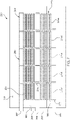
- the heating layer 230 is comprised of a plurality of resistive elements. As described previously, the heating layer may be formed of a single resistive element 40, 140. Alternatively, the heating layer 230 may include a plurality of heating zones that can be independently controlled. For instance, in the embodiment illustrated in Figs. 6-9 , the heating layer 230 includes three heating zones 250, 270 and 290. As described further below, the heating layer 240 comprises a plurality of layers and the three heating zones are spread across two different layers in the heating layer. However, it should be appreciated that the heating layer may be a single layer or may be more than two layers.
- the first zone 250 includes one or more resistive elements 255 extending between a plurality of conductive elements 265, 266.
- the number of resistive elements 255 may vary, however, in the present instance, the first zone 250 includes five resistive elements designated 255A-255E.
- the resistive elements may have different configurations, however in the present instance, each resistive element 255A-255E is substantially similar having a substantially similar resistive value. Accordingly, the following description of resistive element 255 applies to each of resistive elements 255A- 255E.
- Resistive element 255 comprises three sections: a lead 257 at a first end, a tail 258 at a second end, and a body section 260 extending between the lead and the tail.
- the lead 257 forms an electrical connection with conductive element 265 and the tail forms an electrical connection with conductive element 266.
- the body provides an electrical pathway between the lead and the tail.
- the body 260 provides an electrical pathway having sufficient resistance to provide joules effect heating sufficient to raise the temperature of the heating layer 230 when current is passed through the body.
- the resistive elements 255 may be configured in any of a variety of configurations.
- the body 260 may be a generally straight or linear body extending between the first conductor 265 and the second conductor 266. In this way, zone one may comprises a plurality of straight resistive elements extending between the first conductor 265 and the second conductor 266.
- the body 260 of resistive element 255 comprises a convoluted pathway to increase the effective heating area of each heating element.
- the body 260 may comprise a serpentine configuration having a plurality of legs.
- the serpentine path may include a plurality of generally or substantially parallel legs.
- the serpentine path preferably is constrained within a single layer or lamina so that the serpentine path of the body does not cross or overlap itself at any point between the lead 257 and the tail 258.
- the body 260 may have a nominal thickness that is substantially constant along the length of the body. Additionally, the body may form a convoluted reciprocal path, but the body does not cross over itself forming a point or area in which the resistive element has a thickness that is twice the nominal thickness of the body.
- the resistive elements 255 are connected in parallel between the first and second conductive elements 265, 266.
- the first zone 250 of the heating element 230 comprises a first circuit in which the conductor 265 forms a first lead or electrode and the second conductor 266 forms a second lead or electrode with the resistive elements electrically connecting the two electrodes.
- the resistive element is a continuous electrical pathway between the two conductive elements 265, 266.
- the resistive elements comprise a plurality of continuous unidirection carbon fibers forming a convoluted electrical path, such as a serpentine path, between the first electrode 265 and the second electrode 266.
- the carbon fibers are embedded within a matrix of thermoplastic material. More specifically, preferably the carbon fibers are embedded within a thermoplastic resin that is substantially the same as the thermoplastic material forming the matrix material of the structural layers.
- the resistive element may be formed of a narrow unidirectional tape, such as 0.12" wide AS4D/PAEK unidirectional pre-preg tape.
- An exemplary unidirectional carbon fiber tape is TC1225 sold by Tencate as referenced previously.
- the resistive element 255 comprises a unidirectional material such that substantially all of the carbon fibers in the material are parallel. More specifically, preferably substantially all of the carbon fibers have a first end and a second end so that substantially all of the carbon fibers extend the entire length of the resistive element 255 from the lead 257 to the tail 258. In this context, substantially all of the carbon fibers means at least 90% of the carbon fibers in the resistive element.
- the resistive element 255 may be formed into a convoluted shape by heat forming the unidirectional fiber tape.
- a length of unidirectional tape may be heated to a sufficient temperature to cause the thermoplastic material to soften.
- the tape may be heated to a temperature above the glass transition temperature Tg for the thermoplastic matrix material for the tape.
- Tg glass transition temperature
- Tm melting temperature
- the tape may be heated to above approximately 300 °C.
- the resistive element forms a convolute path in which the resistive element does not cross over itself so that the entire length of the resistive element is substantially the same as a single thickness of the tape.
- the tape is cooled to below the glass transition.
- the resistive element 255 provides an electrical path.
- each resistive element follows a convoluted path, such as a serpentine path.
- the resistive element 255 has a central axis that extends from the lead 257 to the tail, following the serpentine path.
- the carbon fibers in the resistive element follow the central axis. In other words, all or substantially all of the carbon fibers in the resistive element are substantially parallel to one another and substantially parallel to the central axis.
- the resistive element 255 is connected with the conductive elements 265, 266 so that the carbon fibers of the resistive element are electrically connected with the conductive elements. More specifically, the conductive elements directly contact the carbon of the carbon fibers. In particular, it should be noted that the carbon fibers may have a coating, referred to as sizing. Preferably, the conductive elements 265, 266 directly contact the carbon fiber so that the carbon fiber provides the electrical path between the conductive elements 265, 266.
- the carbon fibers include a sizing (such as a coating to promote promoting bonding between the carbon fibers and the thermoplastic resin) the sizing may be significantly less conductive that the carbon fiber so that the carbon fiber conducts at least the majority and preferably substantially all of the electricity flowing through the resistive element between the first conductor and the second conductor.
- a sizing such as a coating to promote promoting bonding between the carbon fibers and the thermoplastic resin
- each resistive element 255A-255E provides approximately 46 ohms of resistance.
- the nominal wattage of the first zone at 100 volts AC is approximately 1 100 watts.
- the heating element 230 provides sufficient joules effect heating to raise the surface temperature of the outer surface of upper structural element 225 without raising the temperature of the element 220 above the glass transition temperature for the thermoplastic matrix material in the element.
- the second heating zone 270 is configured substantially similarly to the first heating zone 250.
- the second heating zone 270 comprises a plurality of resistive elements 275A-275E.
- Each of the resistive elements 275 includes a lead 277 electrically connected with a third conductive element 285 and a tail electrically connected with a fourth conductive element 286.
- the resistive elements 275A-275E are connected in parallel with the two conductive elements 285, 286.
- the resistive elements 275A-275E may be formed substantially identically with the resistive elements 255A-255E of the first heating zone 250. However, it may be desirable to vary the configuration of the resistive elements in the second heating zone to vary the heating characteristics of the second heating zone. For instance, in the present instance resistive elements 275 are substantially longer than resistive elements 255. In particular, the body 280 of resistive element 275 may be approximately twice as long as the body 260 of resistive element 255. In this way, if resistive element 275 is formed of the same material as resistive element 255 then resistive element 275 will have substantially higher resistance than resistive element 255. In this way, at the same voltage, the nominal wattage of the second zone is significantly less than the nominal wattage of the first zone 250. For example, at 100 volts AC the wattage of the second heating zone may be approximately 800 watts as opposed to nominally 1 100 watts for the first heating zone.
- Fig. 7 further illustrates the third heating zone 290, which includes a plurality of resistive elements 295A-295E connected in parallel to the fourth conductive element 286 and a fifth conductive element 287.
- the resistive elements 295A-295E may be configured differently from resistive elements 275A-275E, in the present instance resistive elements 295A-295E are substantially identical to resistive elements 275A-275E.
- the first heating zone 250 is on a separate layer than the second and third heating zones 270 290.
- the three heating zones are configured so that the body 260 of each resistive element 255A-255E is positioned below the second and third heating zones so that the body of each resistive element 275, 295 does not overlie the body 260 of each resistive element in the first heating zone. In this way, the heating area provided by the second and third heating zones does not substantially overlap the heating area created by the first heating zone.
- the different layers of the heating element are separated by insulative layers.
- one or more insulative layers may be positioned between the layer having the first heating zone 250 and the layers having the second and third heating zones.
- an insulative layer formed of fiberglass reinforced thermoplastic material may overlie the first heating zone to electrically isolate the first resistive elements 255 from the second and third resistive elements 275, 295.
- the insulative layers may be formed of S2 PEEK layers as described above.
- the laminate 220 is consolidated by heating the assembled plies 225, 226, 230 under pressure. For instance, the assembly may be heated up to a temperature above the melting temperature. The pressure is then removed and the consolidated laminate is cooled to ambient temperature.
- a laminate formed according to such process can then be connected with a power source to create a circuit similar to the circuit shown in Fig. 3 .
- the circuit may include one or more switches to control the power supplied to each of the three heating zones.
- the switches allow power to be supplied independently to one or more of the three heating zones 250, 270, 290.
- the different heating zones may be positioned and configured to apply heat to different parts of the aerostructure.
- the airfoil may have a leading edge, an upper surface and a lower surface.
- the three heating zones may be positioned so that the first heating zone 250 overlies the leading edge of the airfoil, the second heating zone may overlie the upper surface and the third heating zone overlies the lower surface of the airfoil.
- the resistive elements of the three heating zones 250, 270, 290 are configured to provide sufficient heating to raise the temperature of one or more surfaces of the laminate by at least 50 degrees Fahrenheit (10 degrees Celsius) or approximately 30 degrees Celsius.
- the first heating zone may be configured an oriented to raise the temperature of the outer surface of the leading edge by at least approximately 50 degree Fahrenheit (10 degrees Celsius) or approximately 30 degrees Celsius.
- the second zone 270 may heat the upper surface and the third zone may heat the lower surface.
- the system may also include a plurality of sensors.
- the system may include a first sensor sensing a characteristic of a first area, a second sensor sensing a characteristic of a second area and a third sensor sensing a characteristic of a third area. Based on the signals received from the three sensors, the system may independently control the power supplied to each of the three heating zones.
- the first sensor detects the presence of ice on the leading edge and the system controls the power supplied to the first heating zone in response to the signal from the first sensor.
- the system may increase the power supplied to the first heating zone 250 to increase the temperature of the leading edge.
- the system may control the power supplied to the first heating zone by reducing or discontinuing the power supplied to the first heating zone if the first sensor detects a characteristic indicative of a lack of ice on the leading edge. In this way, the system may control the heating of the first zone to increase or decrease the temperature of the leading edge to impede the formation of ice or to melt ice already formed on the leading edge. Similarly, in response to signals received from the second sensor, the system may control the power supplied to the second heating zone to impede the formation of ice or to melt ice already formed on the upper surface. Further still, in response to signals received from the third sensor the system can control the power supplied to the third heating zone to impede the formation of ice or to melt ice already formed on the lower surface.
- the invention might include, relate to, and/or be defined by, the following aspects:
Landscapes
- Engineering & Computer Science (AREA)
- Aviation & Aerospace Engineering (AREA)
- Chemical & Material Sciences (AREA)
- Composite Materials (AREA)
- Mechanical Engineering (AREA)
- Combustion & Propulsion (AREA)
- Resistance Heating (AREA)
- Surface Heating Bodies (AREA)
- Laminated Bodies (AREA)
- Moulding By Coating Moulds (AREA)
Applications Claiming Priority (4)
| Application Number | Priority Date | Filing Date | Title |
|---|---|---|---|
| US201862661917P | 2018-04-24 | 2018-04-24 | |
| EP19793914.3A EP3784488B1 (fr) | 2018-04-24 | 2019-04-24 | Aérostructure composite à élément chauffant intégré |
| PCT/US2019/028978 WO2019209989A1 (fr) | 2018-04-24 | 2019-04-24 | Aérostructure composite à élément chauffant intégré |
| EP20209628.5A EP3800048B1 (fr) | 2018-04-24 | 2019-04-24 | Aérostructure composite dotée d'un élément chauffant intégré |
Related Parent Applications (3)
| Application Number | Title | Priority Date | Filing Date |
|---|---|---|---|
| EP19793914.3A Division EP3784488B1 (fr) | 2018-04-24 | 2019-04-24 | Aérostructure composite à élément chauffant intégré |
| EP19793914.3A Division-Into EP3784488B1 (fr) | 2018-04-24 | 2019-04-24 | Aérostructure composite à élément chauffant intégré |
| EP20209628.5A Division EP3800048B1 (fr) | 2018-04-24 | 2019-04-24 | Aérostructure composite dotée d'un élément chauffant intégré |
Publications (1)
| Publication Number | Publication Date |
|---|---|
| EP4029685A1 true EP4029685A1 (fr) | 2022-07-20 |
Family
ID=68236230
Family Applications (3)
| Application Number | Title | Priority Date | Filing Date |
|---|---|---|---|
| EP22152558.7A Withdrawn EP4029685A1 (fr) | 2018-04-24 | 2019-04-24 | Aérostructure composite dotée d'un élément chauffant intégré |
| EP19793914.3A Active EP3784488B1 (fr) | 2018-04-24 | 2019-04-24 | Aérostructure composite à élément chauffant intégré |
| EP20209628.5A Active EP3800048B1 (fr) | 2018-04-24 | 2019-04-24 | Aérostructure composite dotée d'un élément chauffant intégré |
Family Applications After (2)
| Application Number | Title | Priority Date | Filing Date |
|---|---|---|---|
| EP19793914.3A Active EP3784488B1 (fr) | 2018-04-24 | 2019-04-24 | Aérostructure composite à élément chauffant intégré |
| EP20209628.5A Active EP3800048B1 (fr) | 2018-04-24 | 2019-04-24 | Aérostructure composite dotée d'un élément chauffant intégré |
Country Status (8)
| Country | Link |
|---|---|
| US (3) | US10457405B1 (fr) |
| EP (3) | EP4029685A1 (fr) |
| JP (3) | JP6887576B1 (fr) |
| KR (3) | KR102325147B1 (fr) |
| BR (1) | BR112020021755B1 (fr) |
| ES (1) | ES2992333T3 (fr) |
| PL (1) | PL3800048T3 (fr) |
| WO (1) | WO2019209989A1 (fr) |
Families Citing this family (18)
| Publication number | Priority date | Publication date | Assignee | Title |
|---|---|---|---|---|
| BR112020021755B1 (pt) * | 2018-04-24 | 2022-07-05 | Qarbon Aerospace (Foundation), Llc | Aeroestrutura aquecida |
| US10449749B1 (en) | 2018-05-03 | 2019-10-22 | Triumph Aerostructures, Llc. | Thermoplastic aerostructure with localized ply isolation and method for forming aerostructure |
| US11130559B2 (en) * | 2018-08-20 | 2021-09-28 | Goodrich Corporation | Heated panels with ballistic structures |
| CN111038019B (zh) * | 2019-11-11 | 2022-06-14 | 中国商用飞机有限责任公司 | 复合材料、飞机部件及防冰除冰方法 |
| US11548648B2 (en) * | 2020-01-14 | 2023-01-10 | Goodrich Corporation | Robust power transmission |
| CN112977838A (zh) * | 2021-02-25 | 2021-06-18 | 成都凯天电子股份有限公司 | 一种具有低除冰功耗和高可靠性的嵌入式大气压力传感器 |
| KR102474962B1 (ko) * | 2021-08-13 | 2022-12-07 | 한국항공우주산업 주식회사 | 방제빙용 복합재 구조물과 그 제조 시스템 및 제조 방법 |
| US20230123677A1 (en) * | 2021-10-18 | 2023-04-20 | Goodrich Corporation | Multilayer thermoplastic structure with carbon nanotube heaters |
| US12559240B2 (en) * | 2021-10-18 | 2026-02-24 | Goodrich Corporation | Integrated ice protection system |
| US20230202661A1 (en) * | 2021-10-18 | 2023-06-29 | Goodrich Corporation | Multilayer structure with carbon nanotube heaters |
| FR3128204B1 (fr) * | 2021-10-19 | 2024-07-26 | Safran Aerosystems | Dispositif de degivrage combine |
| US12570127B2 (en) * | 2022-01-26 | 2026-03-10 | GM Global Technology Operations LLC | Temperature compensated, fiber reinforced, structural composite roof |
| EP4289609B1 (fr) * | 2022-06-10 | 2026-04-29 | Rohr, Inc. | Chauffage de matériau thermoplastique utilisant un ou des dispositifs de chauffage électrique pour système d'antigivrage thermique |
| US20230398752A1 (en) * | 2022-06-10 | 2023-12-14 | Rohr, Inc. | Curing thermoset material using electric heater(s) for thermal anti-icing system |
| KR102729616B1 (ko) * | 2022-07-01 | 2024-11-13 | 남선현 | 운반탱크 온도유지장치 |
| CN116280212B (zh) * | 2023-02-03 | 2026-04-14 | 中国民用航空飞行学院 | 防除冰抗风沙旋翼前缘多级微纳结构包片及其制备方法 |
| US20250135734A1 (en) * | 2023-10-26 | 2025-05-01 | GM Global Technology Operations LLC | Systems and methods for resin flow front detection during high pressure resin transfer molding of composite parts |
| WO2025149993A1 (fr) * | 2024-01-11 | 2025-07-17 | 9T Labs Ag | Appareil et procédé de mise en forme et de liaison de dispositifs composites renforcés par des fibres |
Citations (4)
| Publication number | Priority date | Publication date | Assignee | Title |
|---|---|---|---|---|
| US6031214A (en) * | 1996-02-08 | 2000-02-29 | Eurocopter | Device for heating an aerofoil |
| WO2011087412A1 (fr) * | 2010-01-14 | 2011-07-21 | Saab Ab | Système de dégivrage/antigivrage multifonctionnel |
| GB2513652A (en) * | 2013-05-03 | 2014-11-05 | Rolls Royce Plc | Vehicle composite structure |
| US20150344138A1 (en) * | 2014-06-03 | 2015-12-03 | Aurora Flight Sciences Corporation | Multi-functional composite structures |
Family Cites Families (62)
| Publication number | Priority date | Publication date | Assignee | Title |
|---|---|---|---|---|
| US3768760A (en) | 1970-10-30 | 1973-10-30 | Hercules Inc | Graphite fiber composite covering employing multi-directional |
| US4177376A (en) | 1974-09-27 | 1979-12-04 | Raychem Corporation | Layered self-regulating heating article |
| GB8618727D0 (en) | 1986-07-31 | 1986-09-10 | Wiggins Teape Group Ltd | Thermoplastic sheets |
| GB8704852D0 (en) | 1987-03-02 | 1987-04-08 | Welding Inst | Bonding thermoplastic layers |
| IT1215985B (it) | 1988-03-04 | 1990-02-22 | Elca Srl | Procedimento elettrochimico per la realizzazione di rivestimenti di cromo e metalli simili mediante corrente pulsante ad inversione periodica della polarita' |
| US4957577A (en) | 1988-04-04 | 1990-09-18 | Plascore, Inc. | Method for making welded honeycomb core |
| US4942078A (en) * | 1988-09-30 | 1990-07-17 | Rockwell International Corporation | Electrically heated structural composite and method of its manufacture |
| US4990213A (en) | 1988-11-29 | 1991-02-05 | Northrop Corporation | Automated tape laminator head for thermoplastic matrix composite material |
| US5059377A (en) | 1989-07-21 | 1991-10-22 | Aerotrans Corporation | Method for forming a composite structure |
| US5240542A (en) | 1990-09-06 | 1993-08-31 | The Board Of Trustees Of The Leland Stanford Junior University | Joining of composite materials by induction heating |
| AU2338892A (en) | 1991-07-12 | 1993-02-11 | Hexcel Corporation | Method and apparatus for making thermally fused thermoplastic honeycomb structures |
| US5359911A (en) | 1993-06-30 | 1994-11-01 | U.S. Composites Corp. | Lightweight self-insulating composite tool |
| TW253870B (en) | 1994-07-11 | 1995-08-11 | Newell Operating Co | Cellular panel and method and apparatus for making the same |
| US5662293A (en) * | 1995-05-05 | 1997-09-02 | Hower; R. Thomas | Polyimide foam-containing radomes |
| WO1996040551A1 (fr) | 1995-06-07 | 1996-12-19 | The Boeing Company | Poutre composite hybride possedant une ame en metal |
| US5700347A (en) | 1996-01-11 | 1997-12-23 | The Boeing Company | Thermoplastic multi-tape application head |
| US6237874B1 (en) | 1997-09-22 | 2001-05-29 | Northcoast Technologies | Zoned aircraft de-icing system and method |
| US5934617A (en) | 1997-09-22 | 1999-08-10 | Northcoast Technologies | De-ice and anti-ice system and method for aircraft surfaces |
| US6279856B1 (en) | 1997-09-22 | 2001-08-28 | Northcoast Technologies | Aircraft de-icing system |
| US6284089B1 (en) | 1997-12-23 | 2001-09-04 | The Boeing Company | Thermoplastic seam welds |
| US6611659B2 (en) | 1999-04-24 | 2003-08-26 | Airbus Deutschland Gmbh | Electrically heated aircraft composite floor panel |
| JP2002075604A (ja) * | 2000-06-12 | 2002-03-15 | Toto Ltd | 面状ヒータ |
| US6799619B2 (en) | 2002-02-06 | 2004-10-05 | The Boeing Company | Composite material collation machine and associated method for high rate collation of composite materials |
| US7243055B2 (en) | 2004-01-28 | 2007-07-10 | The Boeing Company | Composite stacking sequence optimization for multi-zoned composites |
| US7281318B2 (en) * | 2004-05-19 | 2007-10-16 | The Boeing Company | Method of manufacturing a composite structural member having an integrated electrical circuit |
| JP2008545575A (ja) | 2005-05-27 | 2008-12-18 | ベル ヘリコプター テクストロン インコーポレイテッド | 熱性防氷装置のためのひずみ能力のある導電性/抵抗性複合ハイブリッドヒーター |
| IL185134A (en) * | 2007-08-08 | 2013-10-31 | Amihay Gornik | Mechanical thawing system vibrates |
| GB2453769B (en) * | 2007-10-18 | 2012-09-05 | Gkn Aerospace Services Ltd | An aircraft leading edge thermoplastic heating mat |
| DE102008013759B4 (de) | 2008-03-12 | 2012-12-13 | Airbus Operations Gmbh | Verfahren zur Herstellung eines integralen Faserverbundbauteils sowie Kernform zur Durchführung des Verfahrens |
| DE102008020564B4 (de) | 2008-04-24 | 2013-10-02 | Airbus Operations Gmbh | Tapelegevorrichtung sowie Verfahren zum Aufbau eines Laminats |
| MY153630A (en) * | 2008-08-06 | 2015-02-27 | Lubrizol Advanced Mat Inc | Films and articles made with thermosplastic block copolymers |
| US9004407B2 (en) * | 2008-12-24 | 2015-04-14 | Middle River Aircraft Systems | Anti-icing system and method for preventing ice accumulation |
| JP2012514289A (ja) * | 2008-12-31 | 2012-06-21 | エアバス オペレーションズ ゲーエムベーハー | 少なくとも1つの電熱式の加熱層、及び同加熱層を有する構造コンポーネントを備える加熱システム、加熱方法、並びに加熱機構を有する半完成のコンポーネント又は完成品のコンポーネントの製造方法 |
| JP5744008B2 (ja) * | 2009-04-27 | 2015-07-01 | アプライド ナノストラクチャード ソリューションズ リミテッド ライアビリティー カンパニーApplied Nanostructuredsolutions, Llc | 複合材料構造体を除氷するためのcntベース抵抗加熱 |
| US8158245B2 (en) | 2009-09-24 | 2012-04-17 | Cytec Technology Corp. | Thermoplastic composites and methods of making and using same |
| GB2477340B (en) * | 2010-01-29 | 2011-12-07 | Gkn Aerospace Services Ltd | Electrothermal heater mat |
| GB2477339B (en) * | 2010-01-29 | 2011-12-07 | Gkn Aerospace Services Ltd | Electrothermal heater mat |
| GB201006257D0 (en) | 2010-04-15 | 2010-06-02 | Airbus Operations Ltd | Composite structure |
| EP3575218B1 (fr) * | 2010-12-31 | 2021-08-11 | Battelle Memorial Institute | Antenne avec couche de nanotube de carbone |
| US9227732B2 (en) | 2011-05-23 | 2016-01-05 | Ultra Electronics Ice, Inc. | Electro-thermal ice protection system and method with serial load leveling |
| DE102011119844A1 (de) * | 2011-05-26 | 2012-12-13 | Eads Deutschland Gmbh | Verbundstruktur mit Eisschutzvorrichtung sowie Herstellverfahren |
| US9327839B2 (en) * | 2011-08-05 | 2016-05-03 | General Atomics | Method and apparatus for inhibiting formation of and/or removing ice from aircraft components |
| US9221544B2 (en) * | 2011-09-20 | 2015-12-29 | The Boeing Company | Integrated surface thermal management system |
| US9193466B2 (en) * | 2012-07-13 | 2015-11-24 | Mra Systems, Inc. | Aircraft ice protection system and method |
| KR101532194B1 (ko) | 2012-07-25 | 2015-07-15 | 도레이 카부시키가이샤 | 프리프레그 및 탄소 섬유 강화 복합 재료 |
| FR2996525B1 (fr) * | 2012-10-09 | 2014-11-28 | Aircelle Sa | Element constitutif d’une nacelle a protection contre le givre amelioree |
| KR101449204B1 (ko) * | 2012-12-27 | 2014-10-13 | 주식회사 포스코 | 연속 탄소섬유 강화 열가소성 프리프레그의 제조 방법 |
| ITTO20121152A1 (it) * | 2012-12-27 | 2014-06-28 | Alenia Aermacchi Spa | Gondola motore per un aeromobile, dotata di un sistema integrato di protezione antighiaccio ed assorbimento acustico. |
| WO2014181186A2 (fr) * | 2013-03-15 | 2014-11-13 | Amir Snir | Procédés et système pour dégivrer une surface |
| EP2910365B1 (fr) | 2014-02-21 | 2017-04-26 | Airbus Operations GmbH | Élément structural composite et caisson de torsion |
| US10167550B2 (en) * | 2014-06-03 | 2019-01-01 | Aurora Flight Sciences Corporation | Multi-functional composite structures |
| US10099434B2 (en) * | 2014-09-16 | 2018-10-16 | General Electric Company | Composite airfoil structures |
| US10003053B2 (en) * | 2015-02-04 | 2018-06-19 | Global Web Horizons, Llc | Systems, structures and materials for electrochemical device thermal management |
| US9840043B2 (en) | 2015-02-17 | 2017-12-12 | Bell Helicopter Textron Inc. | Manufacture of thermoplastic core |
| EP3147216B1 (fr) * | 2015-09-23 | 2019-08-07 | Airbus Defence and Space GmbH | Degivrage electrique pour avions |
| US20170238367A1 (en) * | 2016-02-15 | 2017-08-17 | General Electric Company | Integrated Conductive Foam Core for Composite Processing |
| US10986699B2 (en) * | 2016-09-20 | 2021-04-20 | Goodrich Corporation | Thermally conductive, electrically insulating protection layer for de-icing heaters |
| US10457404B2 (en) | 2017-01-31 | 2019-10-29 | Wan Tony Chee | Carbon nanotube anti-icing and de-icing means for aircraft |
| GB2561393B (en) * | 2017-04-13 | 2019-12-04 | Gkn Aerospace Services Ltd | Electrothermal heater |
| CN107386752A (zh) | 2017-07-19 | 2017-11-24 | 天津工业大学 | 一种具有防冰除冰功能的纤维增强复合材料塔杆 |
| BR112020021755B1 (pt) * | 2018-04-24 | 2022-07-05 | Qarbon Aerospace (Foundation), Llc | Aeroestrutura aquecida |
| US10449749B1 (en) | 2018-05-03 | 2019-10-22 | Triumph Aerostructures, Llc. | Thermoplastic aerostructure with localized ply isolation and method for forming aerostructure |
-
2019
- 2019-04-24 BR BR112020021755-7A patent/BR112020021755B1/pt active IP Right Grant
- 2019-04-24 US US16/393,519 patent/US10457405B1/en active Active
- 2019-04-24 KR KR1020207033823A patent/KR102325147B1/ko active Active
- 2019-04-24 WO PCT/US2019/028978 patent/WO2019209989A1/fr not_active Ceased
- 2019-04-24 EP EP22152558.7A patent/EP4029685A1/fr not_active Withdrawn
- 2019-04-24 ES ES19793914T patent/ES2992333T3/es active Active
- 2019-04-24 JP JP2020560372A patent/JP6887576B1/ja active Active
- 2019-04-24 KR KR1020237043302A patent/KR20240000625A/ko not_active Ceased
- 2019-04-24 KR KR1020217036010A patent/KR102615909B1/ko active Active
- 2019-04-24 EP EP19793914.3A patent/EP3784488B1/fr active Active
- 2019-04-24 PL PL20209628.5T patent/PL3800048T3/pl unknown
- 2019-04-24 EP EP20209628.5A patent/EP3800048B1/fr active Active
- 2019-09-09 US US16/564,108 patent/US11577845B2/en active Active
-
2021
- 2021-05-18 JP JP2021083532A patent/JP7234293B2/ja active Active
-
2023
- 2023-02-09 US US18/107,543 patent/US11952131B2/en active Active
- 2023-02-20 JP JP2023024102A patent/JP2023071779A/ja active Pending
Patent Citations (4)
| Publication number | Priority date | Publication date | Assignee | Title |
|---|---|---|---|---|
| US6031214A (en) * | 1996-02-08 | 2000-02-29 | Eurocopter | Device for heating an aerofoil |
| WO2011087412A1 (fr) * | 2010-01-14 | 2011-07-21 | Saab Ab | Système de dégivrage/antigivrage multifonctionnel |
| GB2513652A (en) * | 2013-05-03 | 2014-11-05 | Rolls Royce Plc | Vehicle composite structure |
| US20150344138A1 (en) * | 2014-06-03 | 2015-12-03 | Aurora Flight Sciences Corporation | Multi-functional composite structures |
Also Published As
| Publication number | Publication date |
|---|---|
| US20230182906A1 (en) | 2023-06-15 |
| JP2021516645A (ja) | 2021-07-08 |
| KR102325147B1 (ko) | 2021-11-15 |
| JP6887576B1 (ja) | 2021-06-16 |
| JP7234293B2 (ja) | 2023-03-07 |
| US20190322375A1 (en) | 2019-10-24 |
| US10457405B1 (en) | 2019-10-29 |
| JP2023071779A (ja) | 2023-05-23 |
| WO2019209989A1 (fr) | 2019-10-31 |
| KR20240000625A (ko) | 2024-01-02 |
| EP3800048A1 (fr) | 2021-04-07 |
| US11952131B2 (en) | 2024-04-09 |
| PL3800048T3 (pl) | 2022-07-18 |
| BR112020021755A2 (pt) | 2021-01-26 |
| EP3784488B1 (fr) | 2024-08-21 |
| US20200002010A1 (en) | 2020-01-02 |
| BR112020021755B1 (pt) | 2022-07-05 |
| ES2992333T3 (es) | 2024-12-11 |
| US11577845B2 (en) | 2023-02-14 |
| EP3800048B1 (fr) | 2022-02-23 |
| JP2021151865A (ja) | 2021-09-30 |
| KR102615909B1 (ko) | 2023-12-19 |
| EP3784488A1 (fr) | 2021-03-03 |
| KR20210134848A (ko) | 2021-11-10 |
| EP3784488A4 (fr) | 2021-07-07 |
| KR20210010476A (ko) | 2021-01-27 |
Similar Documents
| Publication | Publication Date | Title |
|---|---|---|
| US11952131B2 (en) | Composite aerostructure with integrated heating element | |
| US10449749B1 (en) | Thermoplastic aerostructure with localized ply isolation and method for forming aerostructure | |
| US6145787A (en) | Device and method for heating and deicing wind energy turbine blades | |
| DK2607075T3 (en) | Sandwich laminate and method of manufacture | |
| EP2523854B1 (fr) | Système de dégivrage/antigivrage multifonctionnel | |
| US20100108661A1 (en) | Multi-layer heating assembly and method | |
| CN102811906A (zh) | 风轮机的多功能除冰/防结冰系统 | |
| EP3244692B1 (fr) | Empilement de couche chauffable électriquement | |
| KR20100075429A (ko) | 표면 난방 시스템 | |
| CN101970217A (zh) | 用于航空器或者航天器的纤维复合物部件 | |
| EP3738883A1 (fr) | Composant chauffé résistif d'aéronef et procédé de fabrication dudit composant d'aéronef | |
| CN206602672U (zh) | 飞机电防冰除冰电加热结构 | |
| US8630534B2 (en) | Heating system and component with such a heating system | |
| EP4289589B1 (fr) | Durcissement de matériau thermodurci utilisant un ou des dispositifs de chauffage électrique pour système d'antigivrage thermique | |
| CN114126107A (zh) | 一种可分区加热的层合结构及成型模具 |
Legal Events
| Date | Code | Title | Description |
|---|---|---|---|
| PUAI | Public reference made under article 153(3) epc to a published international application that has entered the european phase |
Free format text: ORIGINAL CODE: 0009012 |
|
| STAA | Information on the status of an ep patent application or granted ep patent |
Free format text: STATUS: THE APPLICATION HAS BEEN PUBLISHED |
|
| AC | Divisional application: reference to earlier application |
Ref document number: 3784488 Country of ref document: EP Kind code of ref document: P Ref document number: 3800048 Country of ref document: EP Kind code of ref document: P |
|
| AK | Designated contracting states |
Kind code of ref document: A1 Designated state(s): AL AT BE BG CH CY CZ DE DK EE ES FI FR GB GR HR HU IE IS IT LI LT LU LV MC MK MT NL NO PL PT RO RS SE SI SK SM TR |
|
| STAA | Information on the status of an ep patent application or granted ep patent |
Free format text: STATUS: REQUEST FOR EXAMINATION WAS MADE |
|
| 17P | Request for examination filed |
Effective date: 20230112 |
|
| RBV | Designated contracting states (corrected) |
Designated state(s): AL AT BE BG CH CY CZ DE DK EE ES FI FR GB GR HR HU IE IS IT LI LT LU LV MC MK MT NL NO PL PT RO RS SE SI SK SM TR |
|
| STAA | Information on the status of an ep patent application or granted ep patent |
Free format text: STATUS: EXAMINATION IS IN PROGRESS |
|
| 17Q | First examination report despatched |
Effective date: 20250320 |
|
| STAA | Information on the status of an ep patent application or granted ep patent |
Free format text: STATUS: THE APPLICATION HAS BEEN WITHDRAWN |
|
| 18W | Application withdrawn |
Effective date: 20250818 |