EP4029760B1 - Agencement de colonne de direction pour un véhicule - Google Patents
Agencement de colonne de direction pour un véhicule Download PDFInfo
- Publication number
- EP4029760B1 EP4029760B1 EP22151304.7A EP22151304A EP4029760B1 EP 4029760 B1 EP4029760 B1 EP 4029760B1 EP 22151304 A EP22151304 A EP 22151304A EP 4029760 B1 EP4029760 B1 EP 4029760B1
- Authority
- EP
- European Patent Office
- Prior art keywords
- steering column
- bearing block
- column assembly
- steering
- aperture
- Prior art date
- Legal status (The legal status is an assumption and is not a legal conclusion. Google has not performed a legal analysis and makes no representation as to the accuracy of the status listed.)
- Active
Links
Images

Classifications
-
- B—PERFORMING OPERATIONS; TRANSPORTING
- B62—LAND VEHICLES FOR TRAVELLING OTHERWISE THAN ON RAILS
- B62D—MOTOR VEHICLES; TRAILERS
- B62D1/00—Steering controls, i.e. means for initiating a change of direction of the vehicle
- B62D1/02—Steering controls, i.e. means for initiating a change of direction of the vehicle vehicle-mounted
- B62D1/16—Steering columns
- B62D1/18—Steering columns yieldable or adjustable, e.g. tiltable
- B62D1/184—Mechanisms for locking columns at selected positions
Definitions
- the present invention relates to a steering column arrangement for a vehicle, in particular an industrial truck, and to a vehicle, in particular an industrial truck, which comprises such a steering column arrangement.
- steering column arrangements In different types of vehicles and in particular in electrically or internal combustion engine-operated industrial trucks, for example forklifts with electric or hydraulic steering, steering column arrangements have previously been used, which were complexly constructed from a plurality of welded assemblies. These steering columns can generally only be adjusted in height relative to a driver's seat or in terms of their angle of inclination relative to the vertical, in order to allow different drivers of the corresponding vehicle to individually adapt their workplace.
- steering column arrangements are, for example, from the US 2015/239 489 A1 and the JP 2012-030 785 A known.
- the need to use telescopic tubes to adjust the length of the steering column and thus the height of the steering wheel means that there is an increased need for maintenance of the corresponding arrangements.
- the steering column arrangement comprises a steering column with a steering wheel provided thereon, which has a substantially circular cross-section and at least one opening running through the entire cross-section, a bearing block for connecting the steering column to the vehicle body of the vehicle, which has two openings opposite one another, a bearing bolt which, in an assembled state of the steering column arrangement, is guided through the openings of the bearing block and through the opening of the steering column and is fixed by means of fixing means, and a clamping device which is designed and arranged to cause a clamping force through the bearing block on the steering column in a tightened state, wherein the opening of the steering column has a larger dimension in the circumferential direction thereof than the diameter of the bearing bolt in the area in which it lies in the opening of the steering column in the assembled state.
- the steering column can be rotated relative to the bearing block about its longitudinal axis according to the dimensions of the opening therethrough. achieved.
- a stem can also be provided on the upper side of the steering column, which supports the steering wheel in a manner offset from a longitudinal axis of the steering column, a displacement of the steering wheel on a circular path around said longitudinal axis can thus be achieved by such a rotation, which represents an additional degree of freedom for adjusting the position of the steering wheel.
- the present invention can also be used in embodiments in which the steering wheel is arranged concentrically with the steering column, provided that other ergonomic advantages can be achieved by the rotation thereof, for example other add-on components coupled to the steering column can be pivoted to more suitable positions.
- the structure of the steering column arrangement according to the invention is significantly simplified compared to the prior art devices described above, so that a cost reduction and reduced maintenance effort can be achieved.
- the opening in the steering column has a larger dimension in the longitudinal direction than the diameter of the bearing bolt in the area in which it rests in the opening in the steering column in the assembled state, the steering column and thus the steering wheel can also be moved along it Longitudinal axis can be achieved.
- the opening in the steering column cannot be understood as an elongated hole in the strict sense of the word, since it allows adjustment of the steering column according to two degrees of freedom, firstly along its longitudinal axis and secondly rotation around its steering axis.
- a curvature can be provided along its extension, in particular in the longitudinal direction of the steering column.
- at least two such openings can also be provided in the steering column. which would then first allow a rough adjustment of its position along its longitudinal axis or its angle around the longitudinal axis and then a finer adjustment of the corresponding degree of freedom. This makes it possible to avoid excessively large openings which could potentially compromise the mechanical strength of the steering column, while still allowing a large range of adjustment of the position of the steering wheel.
- the steering column arrangement according to the invention can comprise a pair of shell elements, which are provided between the bearing block and the steering column in the assembled state of the steering column arrangement, their internal shape essentially corresponding to the cross-sectional shape of the steering column.
- the clamping force of the clamping device then acts indirectly from the bearing block via the shell elements on the steering column.
- the internal shape of the bearing block could of course also be designed to guide the steering column directly, but this would possibly make it more difficult to assemble the arrangement according to the invention, since inserting the steering column into the bearing block in its final position would then only be possible along its longitudinal axis , while by using the shell elements, the bearing block can be designed in such a way that the assembly formed from the shell elements and the steering column as a whole can also be inserted into the bearing block from one side.
- the shell elements can then be provided with an anti-slip material, in particular on their inner side and/or on their outer side, in order to promote the transmission of the clamping force and to prevent the corresponding component from slipping, whereby in particular a thermoplastic elastomer can be used.
- a further degree of freedom for adjusting the position of the steering wheel is achieved by designing the bearing block and/or the shell elements in such a way that, when the clamping device is in a released state, rotation of the steering column about the bearing pin is possible.
- the clamping device can comprise a clamping lever, which enables an operator to exert a sufficiently high clamping force on the bearing block in order to securely fix the steering column and thus the steering wheel in the desired orientation.
- a clamping lever which enables an operator to exert a sufficiently high clamping force on the bearing block in order to securely fix the steering column and thus the steering wheel in the desired orientation.
- other clamping devices could of course also be used, for example using screw connections or similar.
- the fixing means of the bearing bolt are designed as torsion clamps that can be attached to both ends and are designed to interact with the clamping lever of the clamping device just described, the function of these two components of the arrangement according to the invention can also be combined, so that a particularly simple and compact fixation of the bearing pin and jamming of the steering column in the bearing block.
- At least one of the shell elements, the clamping lever, the bearing bolt and/or the torsion clamp can be formed as an injection-molded part, so that a considerable cost saving can be achieved compared to the above-described welded assemblies from the prior art.
- the present invention further relates to a vehicle, in particular an industrial truck, comprising a steering column arrangement according to one of the preceding claims.
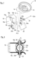
- a steering column arrangement according to the invention is first shown in an isometric exploded view and is generally designated by the reference number 10.
- the steering column arrangement 10 includes a steering column 12 with a substantially circular cross section and an opening 12a running through the entire cross section with a substantially rectangular outline.
- the opening 12a extends both along the longitudinal axis A12 of the steering column 12 and along the circumferential direction thereof.
- a stem 14 is also provided, which carries a steering wheel 16 in a design common for industrial trucks.
- the steering column arrangement 10 comprises a bearing block 18, which is intended to couple the steering column 12 to the vehicle body of the vehicle, not shown, the bearing block 18 consisting of a base plate 18a and two side surfaces 18b and extending from the base plate 18a 18c exists.
- the bearing block 18 consisting of a base plate 18a and two side surfaces 18b and extending from the base plate 18a 18c exists.
- openings 18d and 18e are provided in pairs opposite one another in the two side surfaces 18b and 18c.
- the steering column arrangement 10 comprises a pair of shell elements 20a and 20b, whose outer shape is matched to the inner shape of the two side elements 18b and 18c of the bearing block 18, while their inner shape essentially replicates the circular cross section of the steering column 12.
- a slip-resistant material for example a thermoplastic elastomer.
- a bearing pin 22 is also provided, which in the assembled state consists of Figure 2 both through the opening 12a of the steering column 12 and through the pair of openings 18d in the two side walls 18b and 18c of the bearing block 18.
- a twist clamp 24a or 24b is pushed on, which on the one hand serves to fix the bearing bolt 22 in the position shown together with the head 22a of the bearing bolt 22 or a nut 26 screwed onto it, while between the head 22a and the Clamping lever 28 provided on the torsion clamp 24a or the nut 26 and the torsion clamp 24b with the two Torsional clamps 24a and 24b can interact in such a way that by pressing the clamping lever 28 downwards, the two side walls 18a and 18c of the bearing block are pressed inwards and thus a clamping force is exerted on the steering column 12 via the two shell elements 20a and 20b, which puts it in the corresponding position Position fixed.
- the clamping force acting on the steering column 12 from the side walls 18a and 18b can be reduced to such an extent that it can be displaced relative to the bearing block 18 within a framework specified by the dimensions of the opening 12a and then re-fixed is made possible to adjust the position of the steering wheel 16.
- a rotation of the steering column 12 about its longitudinal axis A12 about the Figure 3 indicated angle ⁇ is possible because the Opening 12a of the steering column 12 has a larger dimension in the circumferential direction than the diameter of the bearing bolt 22 in the area in which it lies in the opening 12a. Due to the fact that the steering wheel 16 is not directly concentric with the circular circumference of the steering column 12, but is spaced from the central longitudinal axis A12 of the steering column, which serves as the axis of rotation, via the stem 14, this rotational movement can thus achieve a displacement of the steering wheel on a circular path around the axis A12, which represents a further degree of freedom for adjusting the position of the steering wheel 16.
- Figure 4 It is also indicated that a rotation of the steering column 12 about the axis A22 defined by the bearing bolts 22 is possible, which enables the steering wheel 14 to be tilted diagonally forward.
- the two shell elements 20a and 20b move together with the steering column 12 within the two side walls 18b and 18c of the bearing block 18, while they remain stationary relative to the bearing block 18 when the steering column 12 is displaced along its longitudinal axis A12 or when the steering column 12 rotates about this axis.
- this steering column arrangement enables the steering wheel 16 to be displaced relative to the bearing block 18 and thus also the vehicle body of the vehicle (not shown) according to three degrees of freedom, which, compared to steering column arrangements known from the prior art, significantly improves ergonomics for the driver of the corresponding vehicle can achieve.
- the fact that the shell elements 20a and 20b, the clamping lever 28, the bearing pin 22 and/or the torsion clamps 24a and 24b can be produced as injection-molded parts results in a significant cost reduction compared to those known from the prior art Steering column arrangements, which were usually manufactured as welded assemblies.
Landscapes
- Engineering & Computer Science (AREA)
- Chemical & Material Sciences (AREA)
- Combustion & Propulsion (AREA)
- Transportation (AREA)
- Mechanical Engineering (AREA)
- Steering Controls (AREA)
Claims (9)
- Agencement de colonne de direction (10) pour un véhicule, en particulier un chariot de manutention, comprenant :- une colonne de direction (12) avec un volant de direction (16) prévu sur celle-ci, qui présente une section transversale sensiblement circulaire et au moins une traversée (12a) s'étendant à travers toute la section transversale ;- un bloc de support (18) pour relier la colonne de direction (12) à la carrosserie du véhicule, qui présente deux traversées (18d) opposées l'une à l'autre ;- un pivot (22) qui, à l'état monté de l'agencement de colonne de direction (10), passe à travers les traversées (18) du bloc de support et à travers la traversée (12a) de la colonne de direction (12) et qui est fixé à l'aide de moyens de fixation (24a, 24b) ; et- un dispositif de serrage (24a, 24b, 26, 28) qui est conçu et disposé de manière à provoquer, dans un état serré, une force de serrage sur la colonne de direction (12) à travers le bloc de support (18) ;dans lequel la traversée (12a) de la colonne de direction (12) présente, dans la direction circonférentielle de celle-ci, une dimension supérieure à celle du diamètre du pivot (22) dans la zone dans laquelle il est logé dans la traversée (12a) de la colonne de direction (12) à l'état monté,caractérisé en ce quele bloc de support (18) et/ou les éléments de coque (20a, 20b) sont conçus de telle sorte que, dans un état desserré du dispositif de serrage (24a, 24b, 26, 28), une rotation de la colonne de direction (12) autour du pivot (22) est possible.
- Agencement de colonne de direction (10) selon la revendication 1,
dans lequel il est en outre prévu, sur le côté supérieur de la colonne de direction (12), une potence (14) qui supporte le volant de direction (16) d'une manière décalée par rapport à un axe longitudinal (A12) de la colonne de direction (12). - Agencement de colonne de direction (10) selon la revendication 1 ou 2, dans lequel la traversée (12a) de la colonne de direction (12) présente, dans la direction longitudinale (A12) de celle-ci, une dimension supérieure à celle du diamètre du pivot (22) dans la zone dans laquelle il est logé dans la traversée (12a) de la colonne de direction (12) à l'état monté.
- Agencement de colonne de direction (10) selon l'une des revendications précédentes,
comprenant en outre une paire d'éléments de coque (20a, 20b) qui, à l'état monté de l'agencement de colonne de direction (10), sont prévus entre le bloc de support (18) et la colonne de direction (12), leur forme intérieure correspondant sensiblement à la forme de la section transversale de la colonne de direction (12). - Agencement de colonne de direction (10) selon la revendication 4,
dans lequel les éléments de coque (20a, 20b) sont pourvus sur leur face intérieure et/ou sur leur face extérieure d'un matériau antidérapant, par exemple d'un élastomère thermoplastique. - Agencement de colonne de direction (10) selon l'une des revendications précédentes,
dans lequel le dispositif de serrage (24a, 24b, 26, 28) comprend un levier de serrage (28). - Agencement de colonne de direction (10) selon la revendication 6,
dans lequel les moyens de fixation (24a, 24b) du pivot (22) sont réalisés sous forme de tendeurs rotatifs (24a, 24b) pouvant être montés aux deux extrémités dudit pivot et sont conçus pour coopérer avec le levier de serrage (28) du dispositif de serrage. - Agencement de colonne de direction (10) selon l'une des revendications précédentes,
dans lequel les éléments de coque (20a, 20b), le levier de serrage (28), le pivot (22) et/ou les tendeurs rotatifs (24a, 24b) sont réalisés sous forme de pièces coulées par injection. - Véhicule, en particulier chariot de manutention, comprenant un agencement de colonne de direction (10) selon l'une des revendications précédentes.
Applications Claiming Priority (1)
| Application Number | Priority Date | Filing Date | Title |
|---|---|---|---|
| DE102021100785.2A DE102021100785A1 (de) | 2021-01-15 | 2021-01-15 | Lenksäulen-anordnung für ein fahrzeug |
Publications (2)
| Publication Number | Publication Date |
|---|---|
| EP4029760A1 EP4029760A1 (fr) | 2022-07-20 |
| EP4029760B1 true EP4029760B1 (fr) | 2024-04-03 |
Family
ID=79601592
Family Applications (1)
| Application Number | Title | Priority Date | Filing Date |
|---|---|---|---|
| EP22151304.7A Active EP4029760B1 (fr) | 2021-01-15 | 2022-01-13 | Agencement de colonne de direction pour un véhicule |
Country Status (3)
| Country | Link |
|---|---|
| EP (1) | EP4029760B1 (fr) |
| CN (1) | CN114763174B (fr) |
| DE (1) | DE102021100785A1 (fr) |
Citations (2)
| Publication number | Priority date | Publication date | Assignee | Title |
|---|---|---|---|---|
| JP2003341527A (ja) * | 2002-05-27 | 2003-12-03 | Nsk Ltd | 車両用ステアリング装置及びその製造方法 |
| DE10260523A1 (de) * | 2002-12-21 | 2004-07-01 | Volkswagen Ag | Verstellbare Sicherheitslenksäule für ein Kraftfahrzeug |
Family Cites Families (8)
| Publication number | Priority date | Publication date | Assignee | Title |
|---|---|---|---|---|
| DE10160303B4 (de) | 2001-12-07 | 2010-04-15 | Linde Material Handling Gmbh | Lenkeinrichtung für eine selbstfahrende Arbeitsmaschine |
| JP5472216B2 (ja) * | 2010-07-06 | 2014-04-16 | 日本精工株式会社 | ステアリング装置 |
| CN102837632A (zh) * | 2011-06-21 | 2012-12-26 | 永恒力集团 | 具有存放架的地面运输车 |
| JP6192565B2 (ja) * | 2014-02-21 | 2017-09-06 | 富士機工株式会社 | ステアリングコラム装置 |
| EP3025929B1 (fr) * | 2014-11-28 | 2017-06-14 | Aktiebolaget SKF | Actionneur d'interface-utilisateur pour un système pilot-by-wire |
| GB201517828D0 (en) * | 2015-10-08 | 2015-11-25 | Trw Ltd And Trw Steering Systems Poland Sp Z O O | A lever for a steering column assembly |
| IT201700121893A1 (it) * | 2017-10-26 | 2019-04-26 | Ferrari Spa | "sistema di sterzatura di un veicolo stradale di tipo "steer by wire" e provvisto di un dispositivo di fine corsa meccanico per il volante" |
| CN212290012U (zh) * | 2020-02-28 | 2021-01-05 | 江苏徐工工程机械研究院有限公司 | 一种高度和角度可调的转向柱 |
-
2021
- 2021-01-15 DE DE102021100785.2A patent/DE102021100785A1/de active Pending
-
2022
- 2022-01-12 CN CN202210039673.2A patent/CN114763174B/zh active Active
- 2022-01-13 EP EP22151304.7A patent/EP4029760B1/fr active Active
Patent Citations (2)
| Publication number | Priority date | Publication date | Assignee | Title |
|---|---|---|---|---|
| JP2003341527A (ja) * | 2002-05-27 | 2003-12-03 | Nsk Ltd | 車両用ステアリング装置及びその製造方法 |
| DE10260523A1 (de) * | 2002-12-21 | 2004-07-01 | Volkswagen Ag | Verstellbare Sicherheitslenksäule für ein Kraftfahrzeug |
Also Published As
| Publication number | Publication date |
|---|---|
| CN114763174A (zh) | 2022-07-19 |
| DE102021100785A1 (de) | 2022-07-21 |
| CN114763174B (zh) | 2026-02-24 |
| EP4029760A1 (fr) | 2022-07-20 |
Similar Documents
| Publication | Publication Date | Title |
|---|---|---|
| EP1671527B1 (fr) | Elément de liason | |
| DE3138083A1 (de) | "verstellbare stuetzvorrichtung fuer lenksaeulen" | |
| DE19934739B4 (de) | Lenkvorrichtung für ein Fahrzeug | |
| DE10013726A1 (de) | Klappenscharnier | |
| DE1555465B1 (de) | Einstellbare Lenksaeule fuer Kraftfahrzeuge | |
| DE102012101386A1 (de) | Lenksäule für ein Kraftfahrzeug | |
| DE10226769C1 (de) | Sicherheitsvorrichtung zum Arretieren eines verstellbaren Anschlussteils | |
| EP4126636B1 (fr) | Colonne de direction pour véhicule automobile | |
| DE68916585T2 (de) | Lenksäulenanordnung. | |
| EP3573851B1 (fr) | Fourche pour articulation et actuateur avec une telle fourche | |
| EP3911553B1 (fr) | Colonne de direction pour un véhicule automobile | |
| DE1405837C3 (de) | Anordnung zum Befestigen eines Gegengewichtes an einem Hublader | |
| DE10141551A1 (de) | Abreißmechanismus am Klemmhebel einer Lenksäule | |
| EP4029760B1 (fr) | Agencement de colonne de direction pour un véhicule | |
| DE69206973T2 (de) | Fahrzeuglenksäule mit einer bereichverstelleinrichtung | |
| EP1382509B1 (fr) | Colonne de direction | |
| DE112021002299B4 (de) | Lenksäule eines fahrzeugs | |
| DE102016206564A1 (de) | Aktuator mit einem Spindelantrieb | |
| DE102019214557A1 (de) | Manteleinheit und Lenksäule für ein Kraftfahrzeug | |
| DE60303527T2 (de) | Kopplungsanordnung | |
| DE3100701A1 (de) | "exzenterverstellung fuer das anlenkauge einer lenkerstange bei radaufhaengungen an kraftfahrzeugen" | |
| EP1223001A2 (fr) | Dispositif de positionnement d'une pièce dans une position définie, en particulier d'une pièce de carrosserie | |
| DE19748117A1 (de) | Kugelzapfen | |
| DE9317971U1 (de) | Spurstangenkopf-Auspreßvorrichtung | |
| EP3334636B1 (fr) | Dispositif de serrage pour une colonne de direction pour un véhicule à moteur |
Legal Events
| Date | Code | Title | Description |
|---|---|---|---|
| PUAI | Public reference made under article 153(3) epc to a published international application that has entered the european phase |
Free format text: ORIGINAL CODE: 0009012 |
|
| STAA | Information on the status of an ep patent application or granted ep patent |
Free format text: STATUS: THE APPLICATION HAS BEEN PUBLISHED |
|
| AK | Designated contracting states |
Kind code of ref document: A1 Designated state(s): AL AT BE BG CH CY CZ DE DK EE ES FI FR GB GR HR HU IE IS IT LI LT LU LV MC MK MT NL NO PL PT RO RS SE SI SK SM TR |
|
| STAA | Information on the status of an ep patent application or granted ep patent |
Free format text: STATUS: REQUEST FOR EXAMINATION WAS MADE |
|
| 17P | Request for examination filed |
Effective date: 20220818 |
|
| RBV | Designated contracting states (corrected) |
Designated state(s): AL AT BE BG CH CY CZ DE DK EE ES FI FR GB GR HR HU IE IS IT LI LT LU LV MC MK MT NL NO PL PT RO RS SE SI SK SM TR |
|
| P01 | Opt-out of the competence of the unified patent court (upc) registered |
Effective date: 20230628 |
|
| GRAP | Despatch of communication of intention to grant a patent |
Free format text: ORIGINAL CODE: EPIDOSNIGR1 |
|
| STAA | Information on the status of an ep patent application or granted ep patent |
Free format text: STATUS: GRANT OF PATENT IS INTENDED |
|
| INTG | Intention to grant announced |
Effective date: 20231020 |
|
| GRAS | Grant fee paid |
Free format text: ORIGINAL CODE: EPIDOSNIGR3 |
|
| GRAA | (expected) grant |
Free format text: ORIGINAL CODE: 0009210 |
|
| STAA | Information on the status of an ep patent application or granted ep patent |
Free format text: STATUS: THE PATENT HAS BEEN GRANTED |
|
| AK | Designated contracting states |
Kind code of ref document: B1 Designated state(s): AL AT BE BG CH CY CZ DE DK EE ES FI FR GB GR HR HU IE IS IT LI LT LU LV MC MK MT NL NO PL PT RO RS SE SI SK SM TR |
|
| REG | Reference to a national code |
Ref country code: CH Ref legal event code: EP |
|
| REG | Reference to a national code |
Ref country code: IE Ref legal event code: FG4D Free format text: LANGUAGE OF EP DOCUMENT: GERMAN |
|
| REG | Reference to a national code |
Ref country code: DE Ref legal event code: R096 Ref document number: 502022000680 Country of ref document: DE |
|
| REG | Reference to a national code |
Ref country code: LT Ref legal event code: MG9D |
|
| REG | Reference to a national code |
Ref country code: NL Ref legal event code: MP Effective date: 20240403 |
|
| PG25 | Lapsed in a contracting state [announced via postgrant information from national office to epo] |
Ref country code: NL Free format text: LAPSE BECAUSE OF FAILURE TO SUBMIT A TRANSLATION OF THE DESCRIPTION OR TO PAY THE FEE WITHIN THE PRESCRIBED TIME-LIMIT Effective date: 20240403 |
|
| PG25 | Lapsed in a contracting state [announced via postgrant information from national office to epo] |
Ref country code: NL Free format text: LAPSE BECAUSE OF FAILURE TO SUBMIT A TRANSLATION OF THE DESCRIPTION OR TO PAY THE FEE WITHIN THE PRESCRIBED TIME-LIMIT Effective date: 20240403 |
|
| PG25 | Lapsed in a contracting state [announced via postgrant information from national office to epo] |
Ref country code: IS Free format text: LAPSE BECAUSE OF FAILURE TO SUBMIT A TRANSLATION OF THE DESCRIPTION OR TO PAY THE FEE WITHIN THE PRESCRIBED TIME-LIMIT Effective date: 20240803 |
|
| PG25 | Lapsed in a contracting state [announced via postgrant information from national office to epo] |
Ref country code: BG Free format text: LAPSE BECAUSE OF FAILURE TO SUBMIT A TRANSLATION OF THE DESCRIPTION OR TO PAY THE FEE WITHIN THE PRESCRIBED TIME-LIMIT Effective date: 20240403 |
|
| PG25 | Lapsed in a contracting state [announced via postgrant information from national office to epo] |
Ref country code: HR Free format text: LAPSE BECAUSE OF FAILURE TO SUBMIT A TRANSLATION OF THE DESCRIPTION OR TO PAY THE FEE WITHIN THE PRESCRIBED TIME-LIMIT Effective date: 20240403 Ref country code: FI Free format text: LAPSE BECAUSE OF FAILURE TO SUBMIT A TRANSLATION OF THE DESCRIPTION OR TO PAY THE FEE WITHIN THE PRESCRIBED TIME-LIMIT Effective date: 20240403 |
|
| PG25 | Lapsed in a contracting state [announced via postgrant information from national office to epo] |
Ref country code: GR Free format text: LAPSE BECAUSE OF FAILURE TO SUBMIT A TRANSLATION OF THE DESCRIPTION OR TO PAY THE FEE WITHIN THE PRESCRIBED TIME-LIMIT Effective date: 20240704 |
|
| PG25 | Lapsed in a contracting state [announced via postgrant information from national office to epo] |
Ref country code: PT Free format text: LAPSE BECAUSE OF FAILURE TO SUBMIT A TRANSLATION OF THE DESCRIPTION OR TO PAY THE FEE WITHIN THE PRESCRIBED TIME-LIMIT Effective date: 20240805 |
|
| PG25 | Lapsed in a contracting state [announced via postgrant information from national office to epo] |
Ref country code: ES Free format text: LAPSE BECAUSE OF FAILURE TO SUBMIT A TRANSLATION OF THE DESCRIPTION OR TO PAY THE FEE WITHIN THE PRESCRIBED TIME-LIMIT Effective date: 20240403 |
|
| PG25 | Lapsed in a contracting state [announced via postgrant information from national office to epo] |
Ref country code: CZ Free format text: LAPSE BECAUSE OF FAILURE TO SUBMIT A TRANSLATION OF THE DESCRIPTION OR TO PAY THE FEE WITHIN THE PRESCRIBED TIME-LIMIT Effective date: 20240403 |
|
| PG25 | Lapsed in a contracting state [announced via postgrant information from national office to epo] |
Ref country code: PL Free format text: LAPSE BECAUSE OF FAILURE TO SUBMIT A TRANSLATION OF THE DESCRIPTION OR TO PAY THE FEE WITHIN THE PRESCRIBED TIME-LIMIT Effective date: 20240403 |
|
| PG25 | Lapsed in a contracting state [announced via postgrant information from national office to epo] |
Ref country code: LV Free format text: LAPSE BECAUSE OF FAILURE TO SUBMIT A TRANSLATION OF THE DESCRIPTION OR TO PAY THE FEE WITHIN THE PRESCRIBED TIME-LIMIT Effective date: 20240403 |
|
| PG25 | Lapsed in a contracting state [announced via postgrant information from national office to epo] |
Ref country code: PT Free format text: LAPSE BECAUSE OF FAILURE TO SUBMIT A TRANSLATION OF THE DESCRIPTION OR TO PAY THE FEE WITHIN THE PRESCRIBED TIME-LIMIT Effective date: 20240805 Ref country code: PL Free format text: LAPSE BECAUSE OF FAILURE TO SUBMIT A TRANSLATION OF THE DESCRIPTION OR TO PAY THE FEE WITHIN THE PRESCRIBED TIME-LIMIT Effective date: 20240403 Ref country code: NO Free format text: LAPSE BECAUSE OF FAILURE TO SUBMIT A TRANSLATION OF THE DESCRIPTION OR TO PAY THE FEE WITHIN THE PRESCRIBED TIME-LIMIT Effective date: 20240703 Ref country code: LV Free format text: LAPSE BECAUSE OF FAILURE TO SUBMIT A TRANSLATION OF THE DESCRIPTION OR TO PAY THE FEE WITHIN THE PRESCRIBED TIME-LIMIT Effective date: 20240403 Ref country code: IS Free format text: LAPSE BECAUSE OF FAILURE TO SUBMIT A TRANSLATION OF THE DESCRIPTION OR TO PAY THE FEE WITHIN THE PRESCRIBED TIME-LIMIT Effective date: 20240803 Ref country code: HR Free format text: LAPSE BECAUSE OF FAILURE TO SUBMIT A TRANSLATION OF THE DESCRIPTION OR TO PAY THE FEE WITHIN THE PRESCRIBED TIME-LIMIT Effective date: 20240403 Ref country code: GR Free format text: LAPSE BECAUSE OF FAILURE TO SUBMIT A TRANSLATION OF THE DESCRIPTION OR TO PAY THE FEE WITHIN THE PRESCRIBED TIME-LIMIT Effective date: 20240704 Ref country code: FI Free format text: LAPSE BECAUSE OF FAILURE TO SUBMIT A TRANSLATION OF THE DESCRIPTION OR TO PAY THE FEE WITHIN THE PRESCRIBED TIME-LIMIT Effective date: 20240403 Ref country code: ES Free format text: LAPSE BECAUSE OF FAILURE TO SUBMIT A TRANSLATION OF THE DESCRIPTION OR TO PAY THE FEE WITHIN THE PRESCRIBED TIME-LIMIT Effective date: 20240403 Ref country code: CZ Free format text: LAPSE BECAUSE OF FAILURE TO SUBMIT A TRANSLATION OF THE DESCRIPTION OR TO PAY THE FEE WITHIN THE PRESCRIBED TIME-LIMIT Effective date: 20240403 Ref country code: BG Free format text: LAPSE BECAUSE OF FAILURE TO SUBMIT A TRANSLATION OF THE DESCRIPTION OR TO PAY THE FEE WITHIN THE PRESCRIBED TIME-LIMIT Effective date: 20240403 Ref country code: RS Free format text: LAPSE BECAUSE OF FAILURE TO SUBMIT A TRANSLATION OF THE DESCRIPTION OR TO PAY THE FEE WITHIN THE PRESCRIBED TIME-LIMIT Effective date: 20240703 |
|
| REG | Reference to a national code |
Ref country code: DE Ref legal event code: R097 Ref document number: 502022000680 Country of ref document: DE |
|
| PG25 | Lapsed in a contracting state [announced via postgrant information from national office to epo] |
Ref country code: DK Free format text: LAPSE BECAUSE OF FAILURE TO SUBMIT A TRANSLATION OF THE DESCRIPTION OR TO PAY THE FEE WITHIN THE PRESCRIBED TIME-LIMIT Effective date: 20240403 |
|
| PG25 | Lapsed in a contracting state [announced via postgrant information from national office to epo] |
Ref country code: EE Free format text: LAPSE BECAUSE OF FAILURE TO SUBMIT A TRANSLATION OF THE DESCRIPTION OR TO PAY THE FEE WITHIN THE PRESCRIBED TIME-LIMIT Effective date: 20240403 |
|
| PG25 | Lapsed in a contracting state [announced via postgrant information from national office to epo] |
Ref country code: RO Free format text: LAPSE BECAUSE OF FAILURE TO SUBMIT A TRANSLATION OF THE DESCRIPTION OR TO PAY THE FEE WITHIN THE PRESCRIBED TIME-LIMIT Effective date: 20240403 Ref country code: SK Free format text: LAPSE BECAUSE OF FAILURE TO SUBMIT A TRANSLATION OF THE DESCRIPTION OR TO PAY THE FEE WITHIN THE PRESCRIBED TIME-LIMIT Effective date: 20240403 |
|
| PG25 | Lapsed in a contracting state [announced via postgrant information from national office to epo] |
Ref country code: SM Free format text: LAPSE BECAUSE OF FAILURE TO SUBMIT A TRANSLATION OF THE DESCRIPTION OR TO PAY THE FEE WITHIN THE PRESCRIBED TIME-LIMIT Effective date: 20240403 |
|
| PG25 | Lapsed in a contracting state [announced via postgrant information from national office to epo] |
Ref country code: SM Free format text: LAPSE BECAUSE OF FAILURE TO SUBMIT A TRANSLATION OF THE DESCRIPTION OR TO PAY THE FEE WITHIN THE PRESCRIBED TIME-LIMIT Effective date: 20240403 Ref country code: SK Free format text: LAPSE BECAUSE OF FAILURE TO SUBMIT A TRANSLATION OF THE DESCRIPTION OR TO PAY THE FEE WITHIN THE PRESCRIBED TIME-LIMIT Effective date: 20240403 Ref country code: RO Free format text: LAPSE BECAUSE OF FAILURE TO SUBMIT A TRANSLATION OF THE DESCRIPTION OR TO PAY THE FEE WITHIN THE PRESCRIBED TIME-LIMIT Effective date: 20240403 Ref country code: EE Free format text: LAPSE BECAUSE OF FAILURE TO SUBMIT A TRANSLATION OF THE DESCRIPTION OR TO PAY THE FEE WITHIN THE PRESCRIBED TIME-LIMIT Effective date: 20240403 Ref country code: DK Free format text: LAPSE BECAUSE OF FAILURE TO SUBMIT A TRANSLATION OF THE DESCRIPTION OR TO PAY THE FEE WITHIN THE PRESCRIBED TIME-LIMIT Effective date: 20240403 |
|
| PLBE | No opposition filed within time limit |
Free format text: ORIGINAL CODE: 0009261 |
|
| STAA | Information on the status of an ep patent application or granted ep patent |
Free format text: STATUS: NO OPPOSITION FILED WITHIN TIME LIMIT |
|
| 26N | No opposition filed |
Effective date: 20250106 |
|
| PG25 | Lapsed in a contracting state [announced via postgrant information from national office to epo] |
Ref country code: SI Free format text: LAPSE BECAUSE OF FAILURE TO SUBMIT A TRANSLATION OF THE DESCRIPTION OR TO PAY THE FEE WITHIN THE PRESCRIBED TIME-LIMIT Effective date: 20240403 |
|
| REG | Reference to a national code |
Ref country code: CH Ref legal event code: PL |
|
| PG25 | Lapsed in a contracting state [announced via postgrant information from national office to epo] |
Ref country code: SE Free format text: LAPSE BECAUSE OF FAILURE TO SUBMIT A TRANSLATION OF THE DESCRIPTION OR TO PAY THE FEE WITHIN THE PRESCRIBED TIME-LIMIT Effective date: 20240403 |
|
| PG25 | Lapsed in a contracting state [announced via postgrant information from national office to epo] |
Ref country code: LU Free format text: LAPSE BECAUSE OF NON-PAYMENT OF DUE FEES Effective date: 20250113 Ref country code: MC Free format text: LAPSE BECAUSE OF FAILURE TO SUBMIT A TRANSLATION OF THE DESCRIPTION OR TO PAY THE FEE WITHIN THE PRESCRIBED TIME-LIMIT Effective date: 20240403 |
|
| PG25 | Lapsed in a contracting state [announced via postgrant information from national office to epo] |
Ref country code: BE Free format text: LAPSE BECAUSE OF NON-PAYMENT OF DUE FEES Effective date: 20250131 |
|
| PG25 | Lapsed in a contracting state [announced via postgrant information from national office to epo] |
Ref country code: CH Free format text: LAPSE BECAUSE OF NON-PAYMENT OF DUE FEES Effective date: 20250131 |
|
| REG | Reference to a national code |
Ref country code: BE Ref legal event code: MM Effective date: 20250131 |
|
| PG25 | Lapsed in a contracting state [announced via postgrant information from national office to epo] |
Ref country code: IE Free format text: LAPSE BECAUSE OF NON-PAYMENT OF DUE FEES Effective date: 20250113 |
|
| PGFP | Annual fee paid to national office [announced via postgrant information from national office to epo] |
Ref country code: DE Payment date: 20260120 Year of fee payment: 5 |
|
| PGFP | Annual fee paid to national office [announced via postgrant information from national office to epo] |
Ref country code: AT Payment date: 20260301 Year of fee payment: 5 |
|
| PGFP | Annual fee paid to national office [announced via postgrant information from national office to epo] |
Ref country code: IT Payment date: 20260130 Year of fee payment: 5 |
|
| PGFP | Annual fee paid to national office [announced via postgrant information from national office to epo] |
Ref country code: FR Payment date: 20260128 Year of fee payment: 5 |