EP4029767B1 - Dispositif d'entraînement à chenille - Google Patents
Dispositif d'entraînement à chenille Download PDFInfo
- Publication number
- EP4029767B1 EP4029767B1 EP21152397.2A EP21152397A EP4029767B1 EP 4029767 B1 EP4029767 B1 EP 4029767B1 EP 21152397 A EP21152397 A EP 21152397A EP 4029767 B1 EP4029767 B1 EP 4029767B1
- Authority
- EP
- European Patent Office
- Prior art keywords
- driving device
- wheels
- teeth
- wheel
- crawler driving
- Prior art date
- Legal status (The legal status is an assumption and is not a legal conclusion. Google has not performed a legal analysis and makes no representation as to the accuracy of the status listed.)
- Active
Links
Images




Classifications
-
- B—PERFORMING OPERATIONS; TRANSPORTING
- B62—LAND VEHICLES FOR TRAVELLING OTHERWISE THAN ON RAILS
- B62D—MOTOR VEHICLES; TRAILERS
- B62D55/00—Endless track vehicles
- B62D55/08—Endless track units; Parts thereof
- B62D55/10—Bogies; Frames
-
- B—PERFORMING OPERATIONS; TRANSPORTING
- B62—LAND VEHICLES FOR TRAVELLING OTHERWISE THAN ON RAILS
- B62D—MOTOR VEHICLES; TRAILERS
- B62D55/00—Endless track vehicles
- B62D55/08—Endless track units; Parts thereof
- B62D55/088—Endless track units; Parts thereof with means to exclude or remove foreign matter, e.g. sealing means, self-cleaning track links or sprockets, deflector plates or scrapers
-
- B—PERFORMING OPERATIONS; TRANSPORTING
- B62—LAND VEHICLES FOR TRAVELLING OTHERWISE THAN ON RAILS
- B62D—MOTOR VEHICLES; TRAILERS
- B62D55/00—Endless track vehicles
- B62D55/08—Endless track units; Parts thereof
- B62D55/14—Arrangement, location, or adaptation of rollers
- B62D55/15—Mounting devices, e.g. bushings, axles, bearings, sealings
-
- B—PERFORMING OPERATIONS; TRANSPORTING
- B62—LAND VEHICLES FOR TRAVELLING OTHERWISE THAN ON RAILS
- B62D—MOTOR VEHICLES; TRAILERS
- B62D55/00—Endless track vehicles
- B62D55/08—Endless track units; Parts thereof
- B62D55/18—Tracks
- B62D55/24—Tracks of continuously flexible type, e.g. rubber belts
- B62D55/244—Moulded in one piece, with either smooth surfaces or surfaces having projections, e.g. incorporating reinforcing elements
-
- B—PERFORMING OPERATIONS; TRANSPORTING
- B62—LAND VEHICLES FOR TRAVELLING OTHERWISE THAN ON RAILS
- B62D—MOTOR VEHICLES; TRAILERS
- B62D55/00—Endless track vehicles
- B62D55/08—Endless track units; Parts thereof
- B62D55/30—Track-tensioning means
Definitions
- the invention belongs to the technology field of agriculture machinery equipment, in particular to a crawler driving device.
- Track is a kind of traditional driving device, with history of more than 200 years since its invention. As excellent traction ability, mobility and stability, it is still a basic form of driving device.
- the crawler driving device is not only used in agriculture tractor, but also mainly used in rice harvester, military vehicles, construction machinery, etc.
- the traditional crawler driving device has the following drawbacks: the roller set is a two-row structure, with a high pressure on each roller wheel and poor stability of the overall structure ;
- the rubber track structure is relatively simple, single-tooth structure located in the middle of the rubber track, easy to cause uneven force on the both sides, thus causing damage to the track;
- the roller wheels are fixed on the track bracket, where there is an obstacle on the ground, the roller wheels bump transmit the impact force received to the machine body, thus causing the machine shake and uncomfortable to driver.
- WO2017/139356 disclosed a kind of track systems for traction of a vehicle in which a spacing of laterally-adjacent ones of the track systems in a widthwise direction of the vehicle is adjustable. This may facilitate use of the vehicle in different conditions. For instance, the spacing of the laterally-adjacent ones of the track systems may be adjustable while the laterally-adjacent ones of the track systems are connected to a power train of the vehicle and/or without requiring use of additional parts such as spacer
- the invention provides a crawler driving device, to solve these problems that mentioned in the above background technology, these problems respectively are the high pressure on roller wheel, uneven pressure on rubber track, and causes the machine body's shake.
- a crawler driving device includes a main frame, a driving wheel that is rotationally set over the main frame, idler wheels that are rotationally set at both ends of the main frame, couple of roller wheels that are fixed under the main frame at intervals along a driving direction of the crawler driving device, and a track that is set at the outside of the driving wheel, the idler wheels and the roller wheels.
- the main frame includes a beam, V-shaped brackets that are linked with both sides of the beam respectively, a connecting rod that is connected to the both V-shaped brackets, a space is formed by the V-shaped brackets to accommodate the driving wheel;
- the idler wheels include guide rods that are set at both ends of the beam respectively, a rotating shaft that is set at the end of each of the guide rods, and the idler wheels are mounted on the both sides of the rotating shaft.
- Each roller wheel includes a mechanical balancer, roller wheels that are rotationally connected with both ends of the mechanical balancer, a center position of the mechanical balancer being rotatably connected with the bottom of the beam. Teeth that are set on the inner wall of the track engageable with the driving wheel, the roller wheels enable the rubber track to move.
- a pin is configured to link the middle position of the both sides of the beam with the bottom of the V-shaped brackets.
- restriction plates are set in the middle position of the both sides of the beam to limit the swing angle of the V-shaped brackets.
- the idler wheels are rotationally set at the two ends of the beam and support the rubber track, the idler wheels including a front idler wheel and a rear idler wheel.
- the mechanical balancer is rotationally installed at the bottom of the both ends of the beam by a pin.
- the mechanical balancer includes a plate, an upper bearing seat that is assembled at the bottom of the both ends of the plate, a lower bearing seat which is used with the upper bearing seat together and form a through-hole between the upper and the lower bearing seats, the through-hole being used for inserting a rotating shaft, and the roller wheels being assembled at the both sides of the rotating shaft.
- the teeth are arranged in three rows, and are set on the inner wall of the rubber track, the three rows of teeth are respectively first row teeth, second row teeth, and third row teeth.
- some teeth that are used for mud cleaning are set at the both sides of the inner wall of the rubber track.
- the crawler driving device further includes a tension mechanism, the tension mechanism including a hydro-cylinder mounted on the connecting rod over the front idler wheel, and tensioning wheels rotationally linked with the hydro-cylinder.
- the tension mechanism including a hydro-cylinder mounted on the connecting rod over the front idler wheel, and tensioning wheels rotationally linked with the hydro-cylinder.
- both sides is the left and right directions along the driving direction of the crawler driving device
- both ends is the front and rear directions along the driving direction of the crawler driving device.
- the invention relates to a crawler driving device, includes the main frame 10, driving wheel 20, idler wheels 30, roller wheels 40, track 50 and tensioning mechanism 60
- the driving wheel 20 rotationally set over the main frame 10 and contact with track 50, and the driving wheel 20 is over the middle position of the main frame along the front and rear directions of the crawler driving device, the idler wheels 30 mounted on the both ends of the main frame 10, couple of roller wheels 40 installed under the both sides of frame body along the driving direction of the crawler driving device, rubber track 50 set at the outside of the driving wheel 20 idler wheels 30 roller wheels 40and tensioning mechanism 60, the teeth on the inner wall of the rubber track 50 engage with driving wheel 20, enabling driving wheel drive rubber track to move .
- described main frame 10 includes beam 11, V-shaped brackets 12 that linked with the both sides of the beam 11 respectively, connecting rod 13 that connected the top of the one V-shaped bracket 12 with the top of the other V-shaped bracket 12; the space that is formed by V-shaped brackets (12) is used to accommodate the driving wheel 20; linking the middle position of the both sides of the beam 11 with the bottom of V-shaped brackets 12 by pin 70.
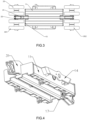
- the beam 11 is composed of three same supporting plates that set at intervals, the both ends of the three supporting plates respectively fixed with plate 15 into a whole ,connecting bracket 17 that connect with the thrust wheel groups 40 is set at the bottom of supporting plates (As shown in FIG.3 )
- the driving wheel 20 includes the rotating fluted disc 21 the side plate 22 the rotating disc 23 the connection bar 24.
- the side plate 22 uniformly distributed and inserted in the teeth of the rotating fluted disc 21, the rectangular notch at the bottom of the side plate 22 stuck out the center of the teeth and perpendicular to the teeth, two rotating disc 23 separately insert in the symmetrical notch at top of the side plate 22, the rotating disc 23 is perpendicular to the side plate 22 and parallel to the rotating fluted disc 21, and the center of two rotating disc is coincident , some holes uniformly set on the two rotating discs 23 and the position of holes in the two rotating disc is same , the connection bar 24 respectively inserted in the corresponding holes of the two rotating discs 23, when walking device works, the connection bar 24 drive the teeth 51 of the inner wall of track 50, thus drive track 50 to walk .
- the idler wheels 30 include guide rod 31 mounted on fixed plate 15 , the other end of guide rod 31 rotating connect with the first rotating shaft 32, the both sides of the first rotating shaft 32 separately connect with two idler wheels 33.
- the idler wheels in the invention is composed of the front idler wheel 301 and the rear idler wheel 302, separately assembled at the front and rear of the beam 11.
- each roller wheel 40 includes mechanical balancer 41, the roller wheel 42 rotating connect with the both ends of the mechanical balancer 41.
- the mechanical balancer 41 includes the plate 411, the upper bearing seat 412 that assembled at the bottom of the both ends of the plates 411, the lower bearing seat 413 that using with upper bearing seat together and form a through-hole 414 between the upper bearing seat and the lower bearing seat , the through-hole 414 used for inserting the second rotating shaft (not show in picture), and the roller wheels 42 assembled at the both sides of the second rotating shaft, and the roller wheels 42 is at the both sides of the plates 411.
- roller wheels 42 for each roller set in the invention.
- the teeth 51 uniformly distributed on the inner wall of the track 50, Set 3 rows teeth 51 on the inner wall of the rubber track 50, respectively are the first row teeth 511, the second row teeth 512, the third row teeth 513; the driving device works, the teeth 51 engage with the driving wheel 20, the driving wheel 20 drive the 3 rows teeth 51 and then the track 50 to rotate, the design of 3 rows teeth 51 make more even force on the track, and effectively improve the force distribution on track 50, and prolong the rubber track 50 life.
- interval space 53 can accommodate the two middle wheels of the idler wheels 30 the roller wheels 40 and the tensioners 60
- tooth 52 Setting some teeth 52 at the two ends of the inner wall of the rubber track 50, and distributed at same interval, the shape of tooth 52 is similar to pyramid make the mud to easily drop from the track 50 and thus achieve the effect of cleaning.
- the tension mechanism 60 includes hydro-cylinder 61, tension wheel group 62, the one end of the hydro-cylinder 61 fixed on the connection rod 13 by supporting bracket 63, the other end link with tensioned 62 by pin.
- driving wheel 20 is installed on driving axle of the machine, when the driving axle turn, the driving wheel move as well, driving wheel 20 engage with the teeth of inner wall of the rubber track, thereby drive track 50 to move, the roller set swing up and down during moving, and also supporting frame for the crawler driving device.
- the roller wheel at the both sides of the main frame can swing up and down with taking the rotating shaft 416 in the middle of the oscillating deck as fulcrum.
- the idler wheels mainly play guiding role, the tension mechanism achieves tensioning adjustment between track and wheel groups under the action of the hydro-cylinder.
Landscapes
- Engineering & Computer Science (AREA)
- Chemical & Material Sciences (AREA)
- Combustion & Propulsion (AREA)
- Transportation (AREA)
- Mechanical Engineering (AREA)
- Harvester Elements (AREA)
Claims (8)
- Un dispositif d'entraînement à chenilles comprenant un cadre principal (10), une roue motrice (20) placée en rotation au-dessus du cadre principal (10), des roues de renvoi (30) placées en rotation aux deux extrémités du cadre principal (10), un couple de roues à rouleaux (40) fixées sous le cadre principal (10) à intervalles le long d'une direction d'entraînement du dispositif d'entraînement à chenilles, et une chenille (50) placée à l'extérieur de la roue motrice (20), des roues de renvoi (30) et des roues à rouleaux (40) ; le cadre principal (10) comprend une poutre (11), des supports en forme de V (12) qui sont reliés aux deux côtés de la poutre (11) respectivement, une bielle (13) qui est reliée aux deux supports en forme de V (12) ; un espace est formé par les supports en forme de V (12) pour accueillir la roue motrice (20) ;les roues de renvoi (30) comprennent des tiges de guidage (31) placées respectivement aux deux extrémités de la poutre (11), un arbre rotatif (32) placé à l'extrémité de chacune des tiges de guidage (31), et les roues de renvoi (33) sont placées des deux côtés de l'arbre rotatif (32) ;chaque roue à rouleaux (40) comprend un équilibreur mécanique (41), des roues à rouleaux (42) qui sont reliées en rotation aux deux extrémités de l'équilibreur mécanique (41), une position centrale de l'équilibreur mécanique (41) étant reliée en rotation au fond de la poutre (11) ;des dents (51) placées sur la paroi intérieure de la chenille (50) en prise avec la roue motrice (20), les roues à rouleaux (42) permettant à la chenille en caoutchouc (50) de se déplacer ;caractérisé par le fait que :
une goupille (70) est configurée pour relier la position médiane des deux côtés de la poutre (11) à la base des supports en forme de V (12). - Le dispositif d'entraînement des chenilles selon la revendication 1, caractérisé par le fait que des plaques de restriction (14) sont placées en position médiane des deux côtés de la poutre (11) pour limiter l'angle de pivotement des supports en forme de V (12).
- Le dispositif d'entraînement de chenilles selon la revendication 1, caractérisé par le fait que les roues de renvoi (30) sont placées en rotation aux deux extrémités de la poutre (11) et supportent la chenille en caoutchouc (50), les roues de renvoi (30) comprenant une roue de renvoi avant (301) et une roue de renvoi arrière (302).
- Le dispositif d'entraînement des chenilles selon la revendication 1, caractérisé par le fait que l'équilibreur mécanique (41) est installé en rotation sous les deux extrémités de la poutre (11) par une goupille.
- Le dispositif d'entraînement de chenilles selon la revendication 4, caractérisé par le fait que l'équilibreur mécanique (41) comprend une plaque (411), un siège de roulement supérieur (412) qui est assemblé au bas des deux extrémités de la plaque (411), un siège de roulement inférieur (413) qui est utilisé avec le siège de roulement supérieur (412) et forme un trou de passage (414) entre le siège de roulement supérieur (412) et le siège de roulement inférieur (413), le trou de passage (414) étant utilisé pour insérer un arbre rotatif, et les roues à rouleaux (42) étant assemblées sur les deux côtés de l'arbre rotatif.
- Le dispositif d'entraînement de chenilles selon la revendication 1, caractérisé par le fait que les dents (51) sont disposées en trois rangées, et sont placées sur la paroi intérieure de la chenille en caoutchouc (50), les trois rangées de dents (51) sont respectivement les dents de la première rangée (511), les dents de la deuxième rangée (512), et les dents de la troisième rangée (513).
- Le dispositif de conduite à chenilles selon la revendication 6, caractérisé par le fait que certaines dents utilisées pour le nettoyage de la boue (52) sont placées des deux côtés de la paroi intérieure de la chenille en caoutchouc (50).
- Le dispositif d'entraînement à chenilles selon la revendication 3, caractérisé par le fait que le dispositif d'entraînement à chenilles comprend en outre un mécanisme de tension (60), et le mécanisme de tension (60) comprend un hydro-cylindre (61) monté sur la bielle (13) au-dessus de la roue de renvoi avant (301), et des roues de tension (62) liées en rotation à l'hydro-cylindre (61).
Priority Applications (1)
| Application Number | Priority Date | Filing Date | Title |
|---|---|---|---|
| EP21152397.2A EP4029767B1 (fr) | 2021-01-19 | 2021-01-19 | Dispositif d'entraînement à chenille |
Applications Claiming Priority (1)
| Application Number | Priority Date | Filing Date | Title |
|---|---|---|---|
| EP21152397.2A EP4029767B1 (fr) | 2021-01-19 | 2021-01-19 | Dispositif d'entraînement à chenille |
Publications (3)
| Publication Number | Publication Date |
|---|---|
| EP4029767A1 EP4029767A1 (fr) | 2022-07-20 |
| EP4029767C0 EP4029767C0 (fr) | 2025-02-19 |
| EP4029767B1 true EP4029767B1 (fr) | 2025-02-19 |
Family
ID=74191636
Family Applications (1)
| Application Number | Title | Priority Date | Filing Date |
|---|---|---|---|
| EP21152397.2A Active EP4029767B1 (fr) | 2021-01-19 | 2021-01-19 | Dispositif d'entraînement à chenille |
Country Status (1)
| Country | Link |
|---|---|
| EP (1) | EP4029767B1 (fr) |
Families Citing this family (3)
| Publication number | Priority date | Publication date | Assignee | Title |
|---|---|---|---|---|
| CN117341849A (zh) * | 2023-11-06 | 2024-01-05 | 成都市新筑交通科技有限公司 | 一种桥梁巡检用履带式走行机构 |
| CN117302374B (zh) * | 2023-11-30 | 2024-01-30 | 河北华臻煤矿机械有限公司 | 一种履带式液压挖掘机履带涨紧装置 |
| CN121180320A (zh) * | 2025-11-10 | 2025-12-23 | 江阴协诚机电科技有限公司 | 矿用履带式移动支护检测装置 |
Family Cites Families (3)
| Publication number | Priority date | Publication date | Assignee | Title |
|---|---|---|---|---|
| US11173971B2 (en) * | 2016-02-08 | 2021-11-16 | Camso Inc. | Tracked vehicle with adjustable track spacing |
| US10737721B2 (en) * | 2016-10-27 | 2020-08-11 | Cnh Industrial America Llc | Steerable drive axle for a tracked work vehicle |
| US10737719B2 (en) * | 2017-11-01 | 2020-08-11 | Deere & Company | Steerable knuckle |
-
2021
- 2021-01-19 EP EP21152397.2A patent/EP4029767B1/fr active Active
Also Published As
| Publication number | Publication date |
|---|---|
| EP4029767C0 (fr) | 2025-02-19 |
| EP4029767A1 (fr) | 2022-07-20 |
Similar Documents
| Publication | Publication Date | Title |
|---|---|---|
| US20220212735A1 (en) | Crawler driving device | |
| EP4029767B1 (fr) | Dispositif d'entraînement à chenille | |
| ES2373581T3 (es) | Unidad de desplazamiento tipo oruga. | |
| US20070290553A1 (en) | Track system for a ground engaging vehicle | |
| CN105073567A (zh) | 用于车辆的橡胶履带单元 | |
| US5505274A (en) | Suspension structure for a continuous track machine | |
| JP2013208953A (ja) | セミクローラ | |
| RU2446974C2 (ru) | Тележка гусеничная сменная для транспортного средства | |
| CA3105064A1 (fr) | Dispositif d'entrainement de chenille | |
| CN103979029B (zh) | 联合收割机橡胶半履带行走装置 | |
| CN214689825U (zh) | 一种高浮动间隙底盘 | |
| CN216709470U (zh) | 一种带增速器的行走机构 | |
| CN216943336U (zh) | 一种拖拉机用橡胶履带行走机构 | |
| CN202089134U (zh) | 一种带有履带式行走机构的半喂入水稻收割机 | |
| CN216709474U (zh) | 一种收割机用橡胶履带行走机构 | |
| CN113525540B (zh) | 四排减震轮组的半履带行走装置 | |
| CN221457823U (zh) | 一种适用于丘陵山地的履带式行走底盘 | |
| JPH0966867A (ja) | クローラ式走行装置の防振機構 | |
| RU2825275C2 (ru) | Гусеничная ходовая часть | |
| CN224022384U (zh) | 一种履带收割机双梁式行走梁 | |
| CN113548121B (zh) | 一种带有减震结构的半履带行走装置 | |
| CN221114151U (zh) | 一种具有组装式架体结构的履带行走装置 | |
| CN206654107U (zh) | 一种三角履带行走装置 | |
| CN222692349U (zh) | 一种再生稻联合收割机行走底盘及再生稻联合收割机 | |
| KR101541224B1 (ko) | 트랙터용 세미크롤러 어셈블리 |
Legal Events
| Date | Code | Title | Description |
|---|---|---|---|
| PUAI | Public reference made under article 153(3) epc to a published international application that has entered the european phase |
Free format text: ORIGINAL CODE: 0009012 |
|
| STAA | Information on the status of an ep patent application or granted ep patent |
Free format text: STATUS: REQUEST FOR EXAMINATION WAS MADE |
|
| 17P | Request for examination filed |
Effective date: 20210217 |
|
| AK | Designated contracting states |
Kind code of ref document: A1 Designated state(s): AL AT BE BG CH CY CZ DE DK EE ES FI FR GB GR HR HU IE IS IT LI LT LU LV MC MK MT NL NO PL PT RO RS SE SI SK SM TR |
|
| GRAP | Despatch of communication of intention to grant a patent |
Free format text: ORIGINAL CODE: EPIDOSNIGR1 |
|
| STAA | Information on the status of an ep patent application or granted ep patent |
Free format text: STATUS: GRANT OF PATENT IS INTENDED |
|
| RIC1 | Information provided on ipc code assigned before grant |
Ipc: B62D 55/30 20060101ALI20240828BHEP Ipc: B62D 55/24 20060101ALI20240828BHEP Ipc: B62D 55/15 20060101ALI20240828BHEP Ipc: B62D 55/10 20060101ALI20240828BHEP Ipc: B62D 55/088 20060101AFI20240828BHEP |
|
| INTG | Intention to grant announced |
Effective date: 20240917 |
|
| GRAS | Grant fee paid |
Free format text: ORIGINAL CODE: EPIDOSNIGR3 |
|
| GRAA | (expected) grant |
Free format text: ORIGINAL CODE: 0009210 |
|
| STAA | Information on the status of an ep patent application or granted ep patent |
Free format text: STATUS: THE PATENT HAS BEEN GRANTED |
|
| AK | Designated contracting states |
Kind code of ref document: B1 Designated state(s): AL AT BE BG CH CY CZ DE DK EE ES FI FR GB GR HR HU IE IS IT LI LT LU LV MC MK MT NL NO PL PT RO RS SE SI SK SM TR |
|
| REG | Reference to a national code |
Ref country code: GB Ref legal event code: FG4D |
|
| REG | Reference to a national code |
Ref country code: CH Ref legal event code: EP |
|
| REG | Reference to a national code |
Ref country code: IE Ref legal event code: FG4D |
|
| REG | Reference to a national code |
Ref country code: DE Ref legal event code: R096 Ref document number: 602021026226 Country of ref document: DE |
|
| U01 | Request for unitary effect filed |
Effective date: 20250228 |
|
| U07 | Unitary effect registered |
Designated state(s): AT BE BG DE DK EE FI FR IT LT LU LV MT NL PT RO SE SI Effective date: 20250307 |
|
| PG25 | Lapsed in a contracting state [announced via postgrant information from national office to epo] |
Ref country code: RS Free format text: LAPSE BECAUSE OF FAILURE TO SUBMIT A TRANSLATION OF THE DESCRIPTION OR TO PAY THE FEE WITHIN THE PRESCRIBED TIME-LIMIT Effective date: 20250519 |
|
| PG25 | Lapsed in a contracting state [announced via postgrant information from national office to epo] |
Ref country code: PL Free format text: LAPSE BECAUSE OF FAILURE TO SUBMIT A TRANSLATION OF THE DESCRIPTION OR TO PAY THE FEE WITHIN THE PRESCRIBED TIME-LIMIT Effective date: 20250219 |
|
| PG25 | Lapsed in a contracting state [announced via postgrant information from national office to epo] |
Ref country code: ES Free format text: LAPSE BECAUSE OF FAILURE TO SUBMIT A TRANSLATION OF THE DESCRIPTION OR TO PAY THE FEE WITHIN THE PRESCRIBED TIME-LIMIT Effective date: 20250219 |
|
| PG25 | Lapsed in a contracting state [announced via postgrant information from national office to epo] |
Ref country code: IS Free format text: LAPSE BECAUSE OF FAILURE TO SUBMIT A TRANSLATION OF THE DESCRIPTION OR TO PAY THE FEE WITHIN THE PRESCRIBED TIME-LIMIT Effective date: 20250619 Ref country code: NO Free format text: LAPSE BECAUSE OF FAILURE TO SUBMIT A TRANSLATION OF THE DESCRIPTION OR TO PAY THE FEE WITHIN THE PRESCRIBED TIME-LIMIT Effective date: 20250519 |
|
| PG25 | Lapsed in a contracting state [announced via postgrant information from national office to epo] |
Ref country code: HR Free format text: LAPSE BECAUSE OF FAILURE TO SUBMIT A TRANSLATION OF THE DESCRIPTION OR TO PAY THE FEE WITHIN THE PRESCRIBED TIME-LIMIT Effective date: 20250219 |
|
| PG25 | Lapsed in a contracting state [announced via postgrant information from national office to epo] |
Ref country code: GR Free format text: LAPSE BECAUSE OF FAILURE TO SUBMIT A TRANSLATION OF THE DESCRIPTION OR TO PAY THE FEE WITHIN THE PRESCRIBED TIME-LIMIT Effective date: 20250520 |
|
| PG25 | Lapsed in a contracting state [announced via postgrant information from national office to epo] |
Ref country code: SM Free format text: LAPSE BECAUSE OF FAILURE TO SUBMIT A TRANSLATION OF THE DESCRIPTION OR TO PAY THE FEE WITHIN THE PRESCRIBED TIME-LIMIT Effective date: 20250219 |
|
| PG25 | Lapsed in a contracting state [announced via postgrant information from national office to epo] |
Ref country code: CZ Free format text: LAPSE BECAUSE OF FAILURE TO SUBMIT A TRANSLATION OF THE DESCRIPTION OR TO PAY THE FEE WITHIN THE PRESCRIBED TIME-LIMIT Effective date: 20250219 |
|
| PG25 | Lapsed in a contracting state [announced via postgrant information from national office to epo] |
Ref country code: SK Free format text: LAPSE BECAUSE OF FAILURE TO SUBMIT A TRANSLATION OF THE DESCRIPTION OR TO PAY THE FEE WITHIN THE PRESCRIBED TIME-LIMIT Effective date: 20250219 |
|
| PLBE | No opposition filed within time limit |
Free format text: ORIGINAL CODE: 0009261 |
|
| STAA | Information on the status of an ep patent application or granted ep patent |
Free format text: STATUS: NO OPPOSITION FILED WITHIN TIME LIMIT |
|
| REG | Reference to a national code |
Ref country code: CH Ref legal event code: L10 Free format text: ST27 STATUS EVENT CODE: U-0-0-L10-L00 (AS PROVIDED BY THE NATIONAL OFFICE) Effective date: 20251231 |
|
| 26N | No opposition filed |
Effective date: 20251120 |
|
| REG | Reference to a national code |
Ref country code: CH Ref legal event code: R17 Free format text: ST27 STATUS EVENT CODE: U-0-0-R10-R17 (AS PROVIDED BY THE NATIONAL OFFICE) Effective date: 20260129 |
|
| REG | Reference to a national code |
Ref country code: CH Ref legal event code: U11 Free format text: ST27 STATUS EVENT CODE: U-0-0-U10-U11 (AS PROVIDED BY THE NATIONAL OFFICE) Effective date: 20260202 |
|
| U20 | Renewal fee for the european patent with unitary effect paid |
Year of fee payment: 6 Effective date: 20260119 |
|
| PGFP | Annual fee paid to national office [announced via postgrant information from national office to epo] |
Ref country code: GB Payment date: 20260119 Year of fee payment: 6 |
|
| PGFP | Annual fee paid to national office [announced via postgrant information from national office to epo] |
Ref country code: MC Payment date: 20260202 Year of fee payment: 6 |
|
| PGFP | Annual fee paid to national office [announced via postgrant information from national office to epo] |
Ref country code: IE Payment date: 20260119 Year of fee payment: 6 |
|
| PGFP | Annual fee paid to national office [announced via postgrant information from national office to epo] |
Ref country code: CH Payment date: 20260202 Year of fee payment: 6 |