EP4029995A1 - Verfahren und schneeräumschild zum entfernen von schnee von einer strassenoberfläche - Google Patents
Verfahren und schneeräumschild zum entfernen von schnee von einer strassenoberfläche Download PDFInfo
- Publication number
- EP4029995A1 EP4029995A1 EP22152322.8A EP22152322A EP4029995A1 EP 4029995 A1 EP4029995 A1 EP 4029995A1 EP 22152322 A EP22152322 A EP 22152322A EP 4029995 A1 EP4029995 A1 EP 4029995A1
- Authority
- EP
- European Patent Office
- Prior art keywords
- road surface
- blade
- snow
- cutting edge
- feeding
- Prior art date
- Legal status (The legal status is an assumption and is not a legal conclusion. Google has not performed a legal analysis and makes no representation as to the accuracy of the status listed.)
- Granted
Links
Images


Classifications
-
- E—FIXED CONSTRUCTIONS
- E01—CONSTRUCTION OF ROADS, RAILWAYS, OR BRIDGES
- E01H—STREET CLEANING; CLEANING OF PERMANENT WAYS; CLEANING BEACHES; DISPERSING OR PREVENTING FOG IN GENERAL CLEANING STREET OR RAILWAY FURNITURE OR TUNNEL WALLS
- E01H10/00—Improving gripping of ice-bound or other slippery traffic surfaces, e.g. using gritting or thawing materials ; Roadside storage of gritting or solid thawing materials; Permanently installed devices for applying gritting or thawing materials; Mobile apparatus specially adapted for treating wintry roads by applying liquid, semi-liquid or granular materials
- E01H10/007—Mobile apparatus specially adapted for preparing or applying liquid or semi-liquid thawing material or spreading granular material on wintry roads
-
- E—FIXED CONSTRUCTIONS
- E01—CONSTRUCTION OF ROADS, RAILWAYS, OR BRIDGES
- E01H—STREET CLEANING; CLEANING OF PERMANENT WAYS; CLEANING BEACHES; DISPERSING OR PREVENTING FOG IN GENERAL CLEANING STREET OR RAILWAY FURNITURE OR TUNNEL WALLS
- E01H5/00—Removing snow or ice from roads or like surfaces; Grading or roughening snow or ice
- E01H5/04—Apparatus propelled by animal or engine power; Apparatus propelled by hand with driven dislodging or conveying levelling elements, conveying pneumatically for the dislodged material
- E01H5/06—Apparatus propelled by animal or engine power; Apparatus propelled by hand with driven dislodging or conveying levelling elements, conveying pneumatically for the dislodged material dislodging essentially by non-driven elements, e.g. scraper blades, snow-plough blades, scoop blades
- E01H5/061—Apparatus propelled by animal or engine power; Apparatus propelled by hand with driven dislodging or conveying levelling elements, conveying pneumatically for the dislodged material dislodging essentially by non-driven elements, e.g. scraper blades, snow-plough blades, scoop blades by scraper blades
-
- E—FIXED CONSTRUCTIONS
- E01—CONSTRUCTION OF ROADS, RAILWAYS, OR BRIDGES
- E01H—STREET CLEANING; CLEANING OF PERMANENT WAYS; CLEANING BEACHES; DISPERSING OR PREVENTING FOG IN GENERAL CLEANING STREET OR RAILWAY FURNITURE OR TUNNEL WALLS
- E01H5/00—Removing snow or ice from roads or like surfaces; Grading or roughening snow or ice
- E01H5/04—Apparatus propelled by animal or engine power; Apparatus propelled by hand with driven dislodging or conveying levelling elements, conveying pneumatically for the dislodged material
- E01H5/06—Apparatus propelled by animal or engine power; Apparatus propelled by hand with driven dislodging or conveying levelling elements, conveying pneumatically for the dislodged material dislodging essentially by non-driven elements, e.g. scraper blades, snow-plough blades, scoop blades
- E01H5/065—Apparatus propelled by animal or engine power; Apparatus propelled by hand with driven dislodging or conveying levelling elements, conveying pneumatically for the dislodged material dislodging essentially by non-driven elements, e.g. scraper blades, snow-plough blades, scoop blades characterised by the form of the snow-plough blade, e.g. flexible, or by snow-plough blade accessories
- E01H5/066—Snow-plough blade accessories, e.g. deflector plates, skid shoes
Definitions
- the invention relates to a method and to a snowplow blade for removing snow from a road surface.
- snowplow blades In order to remove snow from a road surface, snowplow blades are used, which have a snow removal cutting edge.
- the liquid delivered by the nozzles wets the residual snow layer and gets mixed and compressed either by the snow removal cutting edge or by an additional pressing and mixing cutting edge, thus forming a mixture of residual snow and de-icing liquid, in which the de-icing liquid is evenly dispersed in the residual snow, hence causing the melting of the residual snow and avoiding a following icing thereof.
- the de-icing liquid has a relatively high cost and, if it is present in large quantities, can damage or pollute soils and/or attack structures arranged around the road surface. For this reason, it is important - and increasingly necessary - to properly measure the quantity of liquid and limit it to the sole amount needed to melt the residual snow, but it is also important to activate the delivery of said liquid only when strictly needed, namely at the beginning of the snow removal process, and to interrupt said delivery at the end of the snow removal process and, in general, every time the cutting edge, for different reasons, is lifted relative to a predefined snow removal position.
- the control of the delivery is currently carried out by the operator of the machine in a manual manner or by means of solenoid valves controlled by an electronic control unit.
- said electronic command and control devices which can include pressure switches or transducers, are relatively expensive and extremely sensitive to the presence of de-icing liquids, which normally consist of saline solutions and, hence, are relatively aggressive.
- the object of the invention is to provide a snowplow blade, which can solve the problems discussed above in a simple and low-cost fashion, in particular a blade provided with a system for controlling the supply of snow de-icing liquid in an efficient and reliable manner.
- a further object of the invention is to provide a snowplow blade, in which the de-icing liquid supply system does not require any operation or control on the part of the operator carrying out the snow removal process and which operates independently of the environmental conditions in which the snowplow blade is set.
- a snowplow blade for removing snow from a snow-covered road surface; the blade comprising:
- the monostable valve comprises a mobile switching member and the feeler is fixed or hinged to said mobile switching member.
- the feeler is preferably arranged adjacent to said removal cutting edge and, conveniently, downstream of the cutting edge in the forward direction of the blade.
- a further object of the invention is to provide a method for removing snow from a snow-covered road surface.
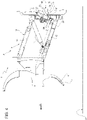
- number 1 indicates, as a whole, a motorised snowplow vehicle, which is partially shown and is designed to remove snow from a snow-covered road surface 2.
- the snowplow vehicle 1 comprises a tractor 3, which is partially shown, and a snowplow blade 4 moved by the tractor 3 in a direction A.
- the blade 4 comprises a known rolling body 5 and a snow removal cutting edge 6, which is firmly connected to a lower portion 7 of the rolling body 5 and projects downward in order to remove at least part of the snow present on the road surface 2.
- both the rolling body 5 and the cutting edge 6 are made of a metal material or of a polymer material.
- the blade 4 further comprises a motorised assembly 8 for attaching the rolling body 5 to the tractor 3 and for moving the rolling body 5 relative to the tractor 3.
- the assembly 8 comprises an attachment plate 9 fixed to the tractor 3, a mobile plate 10 coupled, in a known manner, to the rolling body 5 and an articulated arm 12 comprising a plurality of arms 13 hinged to the fixed plate 9, on one side, and to the mobile plate 10, on the other side.
- the assembly 8 further comprises a hydraulic actuator 14, which is controlled by an operator in order to vertically move the rolling body 5 and the cutting edge 7 from and to the road surface 2 between a lowered snow removing operating position, which is shown in figure 1 , and a lifted waiting position, which is shown in figure 2 .
- the blade 4 further comprises a feeding assembly 15 for feeding a de-icing material onto the residual snow remaining on the road surface 2 following the passage of the cutting edge 6.
- the de-icing material can be a granular material or, conveniently, a liquid solution or a liquid, like in the example described herein.
- the assembly 15 comprises one single delivery channel or one or more delivery nozzles 16, which are known and not described in detail, only one of them being schematically shown in the accompanying figures.
- the delivery nozzles 16 are arranged inside the cutting edge 6.
- the delivery nozzles 16 are arranged on the outside of or adjacent to the cutting edge 6.
- the assembly 15 comprises a (schematically shown) circuit 18 for feeding and controlling the de-icing liquid flow delivered by the delivery nozzles 16 as a function of the position or height of the blade 4 relative to the road surface 2.
- the circuit 18 comprises a monostable shut-off valve 20, namely of the on-off type, which is mechanically operated.
- the valve 20 comprises a valve body 21, which is arranged in a position adjacent to the cutting edge 6 and is preferably - though not necessarily - fixed to the mobile plate 10 behind the rolling body 5 and the cutting edge 6.
- the position of the valve 20 is chosen so as to be as close as possible to the nozzles 16, so as to minimize the quantity of de-icing liquid present between the nozzles 16 and the valve 20.
- the valve 20 has an inlet connected to a de-icing material feeding pipe 22 and an outlet 22A connected to the nozzles 16 in a direct manner or by means of one or more manifolds (which are not shown herein).
- the valve 20 further comprises a mobile switching member 23, which is mechanically connected to a mechanical control device 24 arranged downstream of the cutting edge 6 in the forward direction of the blade 4.
- mechanical control device indicates a completely mechanical device without electric position detecting or commanding and controlling parts.
- the device 24 comprises a stem 25, which is guided in a sliding manner an in opposite directions by a straight guide 26 integral to the fixed plate 10, and a feeler 27, conveniently of the type having a slide, which is fixed or hinged to the lower end of the stem 25.
- the stem 25 and the feeler 27 are pushed towards the road surface 2 and are arranged in an extracted limit stop position of theirs by an elastic body, conveniently a schematically shown helical spring 28, as visible in figure 2 .
- the stem 25 and the feeler 27 move towards their extracted position only due to their weight when the cutting edge is lifted.
- the stem 25 holds the valve 20 in a closing position of its, in which it prevents the de-icing liquid from flowing towards the nozzles 16.
- the position and the length of the stem 25 can be chosen in such a way that, when the cutting edge 6 is arranged in its lowered snow removing position, the feeler 27 cooperates, in a sliding manner, with the road surface 2 or with the residual snow mixed with the de-icing liquid and moves the stem 25 to a retracted position of its, in which it holds the valve 20 in an opening position of its, allowing the de-icing liquid to flow towards the nozzles 16, as visible in figure 1 .
- the delivery of the de-icing liquid towards the nozzles 16 is inhibited.
- the operator of the machine lowers the rolling body 5 and the cutting edge 6 towards their lowered snow removing position.
- the feeler 27 meets the road surface 2 slightly in advance relative to the instant in which the cutting edge 6 reaches its lowered snow removing position and, due to the thrust of the rolling body 5 moving downward, the stem 25 draws back overcoming the action of the spring 28, when present, and switching the valve 20 to an open state so as to start the delivery of the de-icing liquid.
- the feeler 27 loses contact with the road surface 2 and the valve 20 is switched to its closing position and the delivery of the de-icing liquid is interrupted.
- the feeding assembly 15 described herein limits the quantity of de-icing liquid to the essential, since it continuously detects the position or the height of the cutting blade 6 relative to the road surface 2 and interrupts the delivery when the distance of the cutting edge 6 from the road surface 2 exceeds a predetermined threshold value, beyond which delivering the de-icing liquid is useless.
- the feeding assembly 15 operates in a continuous manner and as a function of the height position of the cutting edge 6.
- the feeding assembly 15 evidently controls the delivery of the de-icing material in a completely autonomous manner, with no intervention of the operator of the machine and with no need for any electronic control.
- valve body 21 and the guide 26 are fixed to the fixed plate 9 and the feeler 27 is arranged so as to strike against one of the arms 13.
- the valve 20 is configured to be closed when the stem 25 is arranged in the retracted position and to be open when the stem 25 is pushed by the spring 26 to its extracted position.
- the stroke of the feeler 27 is such that it switches the valve 20 an opening state immediately before the cutting edge 6 reaches its lowered snow removing position and to a closing state when the cutting edge 6 is arranged at a height from the road surface that is greater than the expected removal height.
- the feeler 27 detects, always in a continuous manner, the height position of the cutting edge 6 and the stem 25 causes the valve 20 to close when the arm 13 rotates in a clockwise direction in figures 3 and 4 .
- valve 20 could be arranged in a position other than the one indicated above and the feeler 27 could be manufactured in a different manner from the one described herein by way of example and be coupled to the mobile switching member 23 of the valve 20 in a different manner, for example by means of hinges, levers or other transmission or deflection elements.
- the feeler could cooperate with other mobile elements of the blade 4 or with other mobile elements of the motorised attachment assembly 8, which, in turn, could be different from the one indicated herein by way of example.
- the feeler 27 could cooperate with mobile members carried or moved by the hydraulic actuator 14 or the feeler 27 could cooperate with the output rod of the hydraulic actuator 14.
Landscapes
- Engineering & Computer Science (AREA)
- Architecture (AREA)
- Civil Engineering (AREA)
- Structural Engineering (AREA)
- Cleaning Of Streets, Tracks, Or Beaches (AREA)
Priority Applications (1)
| Application Number | Priority Date | Filing Date | Title |
|---|---|---|---|
| SI202230009T SI4029995T1 (sl) | 2021-01-19 | 2022-01-19 | Postopek in lemež snežnega pluga za odstranjevane snega s površine ceste |
Applications Claiming Priority (1)
| Application Number | Priority Date | Filing Date | Title |
|---|---|---|---|
| IT102021000000857A IT202100000857A1 (it) | 2021-01-19 | 2021-01-19 | Metodo e lama spazzaneve per la rimozione di neve da un manto stradale |
Publications (2)
| Publication Number | Publication Date |
|---|---|
| EP4029995A1 true EP4029995A1 (de) | 2022-07-20 |
| EP4029995B1 EP4029995B1 (de) | 2023-08-30 |
Family
ID=75252743
Family Applications (1)
| Application Number | Title | Priority Date | Filing Date |
|---|---|---|---|
| EP22152322.8A Active EP4029995B1 (de) | 2021-01-19 | 2022-01-19 | Verfahren und schneeräumschild zum entfernen von schnee von einer strassenoberfläche |
Country Status (11)
| Country | Link |
|---|---|
| US (1) | US12195935B2 (de) |
| EP (1) | EP4029995B1 (de) |
| CA (1) | CA3146122A1 (de) |
| DK (1) | DK4029995T3 (de) |
| ES (1) | ES2963671T3 (de) |
| FI (1) | FI4029995T3 (de) |
| HU (1) | HUE063952T2 (de) |
| IT (1) | IT202100000857A1 (de) |
| LT (1) | LT4029995T (de) |
| PL (1) | PL4029995T3 (de) |
| SI (1) | SI4029995T1 (de) |
Citations (5)
| Publication number | Priority date | Publication date | Assignee | Title |
|---|---|---|---|---|
| US3400475A (en) * | 1965-05-28 | 1968-09-10 | Meyer Products Inc | Snow plow |
| US20050204587A1 (en) * | 2004-03-16 | 2005-09-22 | Kime James A | System for controlling the hydraulic actuated components of a truck |
| AT413563B (de) * | 2004-04-15 | 2006-03-15 | Anton Kahlbacher | Schneepflug |
| US7137214B2 (en) * | 2003-04-02 | 2006-11-21 | Cargill, Inc. | Snow removal machine with system for applying a surface treatment material |
| US20190376247A1 (en) * | 2018-05-25 | 2019-12-12 | Giletta S.P.A. | Method and Snow Removal Blade For The Removal of Snow From A Road Surface |
Family Cites Families (3)
| Publication number | Priority date | Publication date | Assignee | Title |
|---|---|---|---|---|
| US5515623A (en) * | 1994-07-29 | 1996-05-14 | Root Spring Scraper Co. | Snowplow with deicer spray attachment |
| US8403595B2 (en) * | 2006-12-01 | 2013-03-26 | David R. Hall | Plurality of liquid jet nozzles and a blower mechanism that are directed into a milling chamber |
| IT1397670B1 (it) * | 2010-01-22 | 2013-01-18 | Giletta Spa | Lama perfezionata per spalare la neve. |
-
2021
- 2021-01-19 IT IT102021000000857A patent/IT202100000857A1/it unknown
-
2022
- 2022-01-17 US US17/577,254 patent/US12195935B2/en active Active
- 2022-01-18 CA CA3146122A patent/CA3146122A1/en active Pending
- 2022-01-19 LT LTEP22152322.8T patent/LT4029995T/lt unknown
- 2022-01-19 FI FIEP22152322.8T patent/FI4029995T3/fi active
- 2022-01-19 ES ES22152322T patent/ES2963671T3/es active Active
- 2022-01-19 HU HUE22152322A patent/HUE063952T2/hu unknown
- 2022-01-19 SI SI202230009T patent/SI4029995T1/sl unknown
- 2022-01-19 PL PL22152322.8T patent/PL4029995T3/pl unknown
- 2022-01-19 DK DK22152322.8T patent/DK4029995T3/da active
- 2022-01-19 EP EP22152322.8A patent/EP4029995B1/de active Active
Patent Citations (5)
| Publication number | Priority date | Publication date | Assignee | Title |
|---|---|---|---|---|
| US3400475A (en) * | 1965-05-28 | 1968-09-10 | Meyer Products Inc | Snow plow |
| US7137214B2 (en) * | 2003-04-02 | 2006-11-21 | Cargill, Inc. | Snow removal machine with system for applying a surface treatment material |
| US20050204587A1 (en) * | 2004-03-16 | 2005-09-22 | Kime James A | System for controlling the hydraulic actuated components of a truck |
| AT413563B (de) * | 2004-04-15 | 2006-03-15 | Anton Kahlbacher | Schneepflug |
| US20190376247A1 (en) * | 2018-05-25 | 2019-12-12 | Giletta S.P.A. | Method and Snow Removal Blade For The Removal of Snow From A Road Surface |
Also Published As
| Publication number | Publication date |
|---|---|
| ES2963671T3 (es) | 2024-04-01 |
| EP4029995B1 (de) | 2023-08-30 |
| SI4029995T1 (sl) | 2024-01-31 |
| HUE063952T2 (hu) | 2024-02-28 |
| CA3146122A1 (en) | 2022-07-19 |
| US12195935B2 (en) | 2025-01-14 |
| PL4029995T3 (pl) | 2024-04-08 |
| IT202100000857A1 (it) | 2022-07-19 |
| FI4029995T3 (fi) | 2023-11-22 |
| LT4029995T (lt) | 2023-12-11 |
| US20220228336A1 (en) | 2022-07-21 |
| DK4029995T3 (da) | 2023-11-27 |
Similar Documents
| Publication | Publication Date | Title |
|---|---|---|
| US4182444A (en) | Heated conveyor belt scraper | |
| KR100628959B1 (ko) | 차량 윈도우를 세척하거나 제빙하기 위한 장치 | |
| US8500363B1 (en) | Compactor having controllable edge wheel spray system | |
| EP4029995B1 (de) | Verfahren und schneeräumschild zum entfernen von schnee von einer strassenoberfläche | |
| CN100567664C (zh) | 挖土机行程控制装置 | |
| WO2008144209A4 (en) | Ice management apparatus | |
| KR101707677B1 (ko) | 제설기용 삽날의 승하강을 돕기 위한 유압장치 | |
| CN101456406B (zh) | 一种雨刮臂升降装置及控制方法 | |
| KR101567934B1 (ko) | 적설량과 도로상황에 따른 제설압력 조절이 가능한 제설기 | |
| RU2846938C2 (ru) | Снегоуборочный плуг для уборки снега с дорожной поверхности и способ уборки снега с покрытой снегом дорожной поверхности посредством использования снегоуборочного плуга | |
| CN211368565U (zh) | 一种可装卸式融雪剂撒布上装的集成控制装置 | |
| EP3572587B1 (de) | Verfahren und schneeräumschild zur entfernung von schnee von einer fahrbahn | |
| JP2012096652A (ja) | 車両ガラスの氷結体解凍装置 | |
| US4070831A (en) | Hydraulic drive circuit for machine tools | |
| CN116540572A (zh) | 一种自动化融雪撒布车的控制方法及控制系统 | |
| CN102128277A (zh) | 一种格式闸门 | |
| EP3144429B1 (de) | Nutzfahrzeug | |
| RU2022101001A (ru) | Способ и снегоуборочный плуг для уборки снега с дорожной поверхности | |
| JP3589942B2 (ja) | キャスタホイール調整の遠隔操作方法 | |
| CN116215455A (zh) | 具有防冻功能的传感器清洁系统 | |
| CN108487376B (zh) | 一种管道防冻裂保护装置 | |
| CN220462215U (zh) | 一种自清理塞棒 | |
| CN116815587B (zh) | 一种半柔性路面水泥基砂浆浇筑装置及其浇筑方法 | |
| CA1302808C (en) | Control system for expelling liquid from a pneumatic actuator | |
| DE19950293A1 (de) | Antriebsvorrichtung für Scheibenwischer von Kraftfahrzeugen |
Legal Events
| Date | Code | Title | Description |
|---|---|---|---|
| PUAI | Public reference made under article 153(3) epc to a published international application that has entered the european phase |
Free format text: ORIGINAL CODE: 0009012 |
|
| STAA | Information on the status of an ep patent application or granted ep patent |
Free format text: STATUS: THE APPLICATION HAS BEEN PUBLISHED |
|
| AK | Designated contracting states |
Kind code of ref document: A1 Designated state(s): AL AT BE BG CH CY CZ DE DK EE ES FI FR GB GR HR HU IE IS IT LI LT LU LV MC MK MT NL NO PL PT RO RS SE SI SK SM TR |
|
| STAA | Information on the status of an ep patent application or granted ep patent |
Free format text: STATUS: REQUEST FOR EXAMINATION WAS MADE |
|
| 17P | Request for examination filed |
Effective date: 20230111 |
|
| RBV | Designated contracting states (corrected) |
Designated state(s): AL AT BE BG CH CY CZ DE DK EE ES FI FR GB GR HR HU IE IS IT LI LT LU LV MC MK MT NL NO PL PT RO RS SE SI SK SM TR |
|
| GRAP | Despatch of communication of intention to grant a patent |
Free format text: ORIGINAL CODE: EPIDOSNIGR1 |
|
| STAA | Information on the status of an ep patent application or granted ep patent |
Free format text: STATUS: GRANT OF PATENT IS INTENDED |
|
| INTG | Intention to grant announced |
Effective date: 20230317 |
|
| P01 | Opt-out of the competence of the unified patent court (upc) registered |
Effective date: 20230524 |
|
| GRAS | Grant fee paid |
Free format text: ORIGINAL CODE: EPIDOSNIGR3 |
|
| GRAA | (expected) grant |
Free format text: ORIGINAL CODE: 0009210 |
|
| STAA | Information on the status of an ep patent application or granted ep patent |
Free format text: STATUS: THE PATENT HAS BEEN GRANTED |
|
| AK | Designated contracting states |
Kind code of ref document: B1 Designated state(s): AL AT BE BG CH CY CZ DE DK EE ES FI FR GB GR HR HU IE IS IT LI LT LU LV MC MK MT NL NO PL PT RO RS SE SI SK SM TR |
|
| REG | Reference to a national code |
Ref country code: GB Ref legal event code: FG4D |
|
| REG | Reference to a national code |
Ref country code: CH Ref legal event code: EP |
|
| REG | Reference to a national code |
Ref country code: IE Ref legal event code: FG4D |
|
| REG | Reference to a national code |
Ref country code: DE Ref legal event code: R096 Ref document number: 602022000391 Country of ref document: DE |
|
| REG | Reference to a national code |
Ref country code: NL Ref legal event code: FP |
|
| REG | Reference to a national code |
Ref country code: SE Ref legal event code: TRGR |
|
| REG | Reference to a national code |
Ref country code: FI Ref legal event code: FGE |
|
| REG | Reference to a national code |
Ref country code: DK Ref legal event code: T3 Effective date: 20231124 |
|
| REG | Reference to a national code |
Ref country code: NO Ref legal event code: T2 Effective date: 20230830 |
|
| PG25 | Lapsed in a contracting state [announced via postgrant information from national office to epo] |
Ref country code: GR Free format text: LAPSE BECAUSE OF FAILURE TO SUBMIT A TRANSLATION OF THE DESCRIPTION OR TO PAY THE FEE WITHIN THE PRESCRIBED TIME-LIMIT Effective date: 20231201 |
|
| PG25 | Lapsed in a contracting state [announced via postgrant information from national office to epo] |
Ref country code: IS Free format text: LAPSE BECAUSE OF FAILURE TO SUBMIT A TRANSLATION OF THE DESCRIPTION OR TO PAY THE FEE WITHIN THE PRESCRIBED TIME-LIMIT Effective date: 20231230 |
|
| PG25 | Lapsed in a contracting state [announced via postgrant information from national office to epo] |
Ref country code: RS Free format text: LAPSE BECAUSE OF FAILURE TO SUBMIT A TRANSLATION OF THE DESCRIPTION OR TO PAY THE FEE WITHIN THE PRESCRIBED TIME-LIMIT Effective date: 20230830 Ref country code: LV Free format text: LAPSE BECAUSE OF FAILURE TO SUBMIT A TRANSLATION OF THE DESCRIPTION OR TO PAY THE FEE WITHIN THE PRESCRIBED TIME-LIMIT Effective date: 20230830 Ref country code: IS Free format text: LAPSE BECAUSE OF FAILURE TO SUBMIT A TRANSLATION OF THE DESCRIPTION OR TO PAY THE FEE WITHIN THE PRESCRIBED TIME-LIMIT Effective date: 20231230 Ref country code: HR Free format text: LAPSE BECAUSE OF FAILURE TO SUBMIT A TRANSLATION OF THE DESCRIPTION OR TO PAY THE FEE WITHIN THE PRESCRIBED TIME-LIMIT Effective date: 20230830 Ref country code: GR Free format text: LAPSE BECAUSE OF FAILURE TO SUBMIT A TRANSLATION OF THE DESCRIPTION OR TO PAY THE FEE WITHIN THE PRESCRIBED TIME-LIMIT Effective date: 20231201 |
|
| REG | Reference to a national code |
Ref country code: SK Ref legal event code: T3 Ref document number: E 42840 Country of ref document: SK |
|
| REG | Reference to a national code |
Ref country code: EE Ref legal event code: FG4A Ref document number: E023839 Country of ref document: EE Effective date: 20231117 |
|
| REG | Reference to a national code |
Ref country code: HU Ref legal event code: AG4A Ref document number: E063952 Country of ref document: HU |
|
| REG | Reference to a national code |
Ref country code: ES Ref legal event code: FG2A Ref document number: 2963671 Country of ref document: ES Kind code of ref document: T3 Effective date: 20240401 |
|
| PG25 | Lapsed in a contracting state [announced via postgrant information from national office to epo] |
Ref country code: SM Free format text: LAPSE BECAUSE OF FAILURE TO SUBMIT A TRANSLATION OF THE DESCRIPTION OR TO PAY THE FEE WITHIN THE PRESCRIBED TIME-LIMIT Effective date: 20230830 Ref country code: PT Free format text: LAPSE BECAUSE OF FAILURE TO SUBMIT A TRANSLATION OF THE DESCRIPTION OR TO PAY THE FEE WITHIN THE PRESCRIBED TIME-LIMIT Effective date: 20240102 |
|
| REG | Reference to a national code |
Ref country code: AT Ref legal event code: UEP Ref document number: 1605600 Country of ref document: AT Kind code of ref document: T Effective date: 20230830 |
|
| REG | Reference to a national code |
Ref country code: DE Ref legal event code: R097 Ref document number: 602022000391 Country of ref document: DE |
|
| PLBE | No opposition filed within time limit |
Free format text: ORIGINAL CODE: 0009261 |
|
| STAA | Information on the status of an ep patent application or granted ep patent |
Free format text: STATUS: NO OPPOSITION FILED WITHIN TIME LIMIT |
|
| 26N | No opposition filed |
Effective date: 20240603 |
|
| PG25 | Lapsed in a contracting state [announced via postgrant information from national office to epo] |
Ref country code: MC Free format text: LAPSE BECAUSE OF FAILURE TO SUBMIT A TRANSLATION OF THE DESCRIPTION OR TO PAY THE FEE WITHIN THE PRESCRIBED TIME-LIMIT Effective date: 20230830 |
|
| PG25 | Lapsed in a contracting state [announced via postgrant information from national office to epo] |
Ref country code: MC Free format text: LAPSE BECAUSE OF FAILURE TO SUBMIT A TRANSLATION OF THE DESCRIPTION OR TO PAY THE FEE WITHIN THE PRESCRIBED TIME-LIMIT Effective date: 20230830 |
|
| PG25 | Lapsed in a contracting state [announced via postgrant information from national office to epo] |
Ref country code: LU Free format text: LAPSE BECAUSE OF NON-PAYMENT OF DUE FEES Effective date: 20240119 |
|
| PG25 | Lapsed in a contracting state [announced via postgrant information from national office to epo] |
Ref country code: LU Free format text: LAPSE BECAUSE OF NON-PAYMENT OF DUE FEES Effective date: 20240119 |
|
| PG25 | Lapsed in a contracting state [announced via postgrant information from national office to epo] |
Ref country code: BG Free format text: LAPSE BECAUSE OF FAILURE TO SUBMIT A TRANSLATION OF THE DESCRIPTION OR TO PAY THE FEE WITHIN THE PRESCRIBED TIME-LIMIT Effective date: 20230830 |
|
| PG25 | Lapsed in a contracting state [announced via postgrant information from national office to epo] |
Ref country code: BG Free format text: LAPSE BECAUSE OF FAILURE TO SUBMIT A TRANSLATION OF THE DESCRIPTION OR TO PAY THE FEE WITHIN THE PRESCRIBED TIME-LIMIT Effective date: 20230830 |
|
| PG25 | Lapsed in a contracting state [announced via postgrant information from national office to epo] |
Ref country code: IE Free format text: LAPSE BECAUSE OF NON-PAYMENT OF DUE FEES Effective date: 20240119 |
|
| PG25 | Lapsed in a contracting state [announced via postgrant information from national office to epo] |
Ref country code: IE Free format text: LAPSE BECAUSE OF NON-PAYMENT OF DUE FEES Effective date: 20240119 |
|
| PG25 | Lapsed in a contracting state [announced via postgrant information from national office to epo] |
Ref country code: CY Free format text: LAPSE BECAUSE OF FAILURE TO SUBMIT A TRANSLATION OF THE DESCRIPTION OR TO PAY THE FEE WITHIN THE PRESCRIBED TIME-LIMIT; INVALID AB INITIO Effective date: 20220119 |
|
| PGFP | Annual fee paid to national office [announced via postgrant information from national office to epo] |
Ref country code: HU Payment date: 20260127 Year of fee payment: 5 |
|
| REG | Reference to a national code |
Ref country code: CH Ref legal event code: U11 Free format text: ST27 STATUS EVENT CODE: U-0-0-U10-U11 (AS PROVIDED BY THE NATIONAL OFFICE) Effective date: 20260227 |
|
| PGFP | Annual fee paid to national office [announced via postgrant information from national office to epo] |
Ref country code: NL Payment date: 20260226 Year of fee payment: 5 |
|
| PGFP | Annual fee paid to national office [announced via postgrant information from national office to epo] |
Ref country code: SE Payment date: 20260127 Year of fee payment: 5 |
|
| PGFP | Annual fee paid to national office [announced via postgrant information from national office to epo] |
Ref country code: GB Payment date: 20260227 Year of fee payment: 5 Ref country code: LT Payment date: 20260120 Year of fee payment: 5 |
|
| PGFP | Annual fee paid to national office [announced via postgrant information from national office to epo] |
Ref country code: ES Payment date: 20260202 Year of fee payment: 5 |
|
| PGFP | Annual fee paid to national office [announced via postgrant information from national office to epo] |
Ref country code: NO Payment date: 20260128 Year of fee payment: 5 Ref country code: DK Payment date: 20260126 Year of fee payment: 5 Ref country code: DE Payment date: 20260128 Year of fee payment: 5 |
|
| PGFP | Annual fee paid to national office [announced via postgrant information from national office to epo] |
Ref country code: AT Payment date: 20260301 Year of fee payment: 5 |
|
| PGFP | Annual fee paid to national office [announced via postgrant information from national office to epo] |
Ref country code: RO Payment date: 20260126 Year of fee payment: 5 Ref country code: BE Payment date: 20260127 Year of fee payment: 5 Ref country code: FI Payment date: 20260126 Year of fee payment: 5 Ref country code: IT Payment date: 20260102 Year of fee payment: 5 |
|
| PGFP | Annual fee paid to national office [announced via postgrant information from national office to epo] |
Ref country code: FR Payment date: 20260126 Year of fee payment: 5 |
|
| PGFP | Annual fee paid to national office [announced via postgrant information from national office to epo] |
Ref country code: TR Payment date: 20260127 Year of fee payment: 5 |
|
| PGFP | Annual fee paid to national office [announced via postgrant information from national office to epo] |
Ref country code: CH Payment date: 20260227 Year of fee payment: 5 Ref country code: CZ Payment date: 20260120 Year of fee payment: 5 |
|
| PGFP | Annual fee paid to national office [announced via postgrant information from national office to epo] |
Ref country code: PL Payment date: 20260120 Year of fee payment: 5 |
|
| PGFP | Annual fee paid to national office [announced via postgrant information from national office to epo] |
Ref country code: EE Payment date: 20260129 Year of fee payment: 5 Ref country code: SK Payment date: 20260121 Year of fee payment: 5 |
|
| PGFP | Annual fee paid to national office [announced via postgrant information from national office to epo] |
Ref country code: SI Payment date: 20260119 Year of fee payment: 5 |