EP4030085B1 - Fluidkreislauf für ein kraftfahrzeug - Google Patents
Fluidkreislauf für ein kraftfahrzeug Download PDFInfo
- Publication number
- EP4030085B1 EP4030085B1 EP21305062.8A EP21305062A EP4030085B1 EP 4030085 B1 EP4030085 B1 EP 4030085B1 EP 21305062 A EP21305062 A EP 21305062A EP 4030085 B1 EP4030085 B1 EP 4030085B1
- Authority
- EP
- European Patent Office
- Prior art keywords
- piston
- window
- outlet port
- fluid circuit
- way valve
- Prior art date
- Legal status (The legal status is an assumption and is not a legal conclusion. Google has not performed a legal analysis and makes no representation as to the accuracy of the status listed.)
- Active
Links
Images

Classifications
-
- F—MECHANICAL ENGINEERING; LIGHTING; HEATING; WEAPONS; BLASTING
- F01—MACHINES OR ENGINES IN GENERAL; ENGINE PLANTS IN GENERAL; STEAM ENGINES
- F01P—COOLING OF MACHINES OR ENGINES IN GENERAL; COOLING OF INTERNAL-COMBUSTION ENGINES
- F01P7/00—Controlling of coolant flow
- F01P7/14—Controlling of coolant flow the coolant being liquid
- F01P7/16—Controlling of coolant flow the coolant being liquid by thermostatic control
- F01P7/165—Controlling of coolant flow the coolant being liquid by thermostatic control characterised by systems with two or more loops
-
- F—MECHANICAL ENGINEERING; LIGHTING; HEATING; WEAPONS; BLASTING
- F16—ENGINEERING ELEMENTS AND UNITS; GENERAL MEASURES FOR PRODUCING AND MAINTAINING EFFECTIVE FUNCTIONING OF MACHINES OR INSTALLATIONS; THERMAL INSULATION IN GENERAL
- F16K—VALVES; TAPS; COCKS; ACTUATING-FLOATS; DEVICES FOR VENTING OR AERATING
- F16K11/00—Multiple-way valves, e.g. mixing valves; Pipe fittings incorporating such valves
- F16K11/02—Multiple-way valves, e.g. mixing valves; Pipe fittings incorporating such valves with all movable sealing faces moving as one unit
- F16K11/06—Multiple-way valves, e.g. mixing valves; Pipe fittings incorporating such valves with all movable sealing faces moving as one unit comprising only sliding valves, i.e. sliding closure elements
- F16K11/065—Multiple-way valves, e.g. mixing valves; Pipe fittings incorporating such valves with all movable sealing faces moving as one unit comprising only sliding valves, i.e. sliding closure elements with linearly sliding closure members
- F16K11/07—Multiple-way valves, e.g. mixing valves; Pipe fittings incorporating such valves with all movable sealing faces moving as one unit comprising only sliding valves, i.e. sliding closure elements with linearly sliding closure members with cylindrical slides
- F16K11/0716—Multiple-way valves, e.g. mixing valves; Pipe fittings incorporating such valves with all movable sealing faces moving as one unit comprising only sliding valves, i.e. sliding closure elements with linearly sliding closure members with cylindrical slides with fluid passages through the valve member
-
- F—MECHANICAL ENGINEERING; LIGHTING; HEATING; WEAPONS; BLASTING
- F16—ENGINEERING ELEMENTS AND UNITS; GENERAL MEASURES FOR PRODUCING AND MAINTAINING EFFECTIVE FUNCTIONING OF MACHINES OR INSTALLATIONS; THERMAL INSULATION IN GENERAL
- F16K—VALVES; TAPS; COCKS; ACTUATING-FLOATS; DEVICES FOR VENTING OR AERATING
- F16K11/00—Multiple-way valves, e.g. mixing valves; Pipe fittings incorporating such valves
- F16K11/10—Multiple-way valves, e.g. mixing valves; Pipe fittings incorporating such valves with two or more closure members not moving as a unit
- F16K11/105—Three-way check or safety valves with two or more closure members
-
- F—MECHANICAL ENGINEERING; LIGHTING; HEATING; WEAPONS; BLASTING
- F01—MACHINES OR ENGINES IN GENERAL; ENGINE PLANTS IN GENERAL; STEAM ENGINES
- F01M—LUBRICATING OF MACHINES OR ENGINES IN GENERAL; LUBRICATING INTERNAL COMBUSTION ENGINES; CRANKCASE VENTILATING
- F01M5/00—Heating, cooling, or controlling temperature of lubricant; Lubrication means facilitating engine starting
- F01M5/002—Cooling
-
- F—MECHANICAL ENGINEERING; LIGHTING; HEATING; WEAPONS; BLASTING
- F01—MACHINES OR ENGINES IN GENERAL; ENGINE PLANTS IN GENERAL; STEAM ENGINES
- F01M—LUBRICATING OF MACHINES OR ENGINES IN GENERAL; LUBRICATING INTERNAL COMBUSTION ENGINES; CRANKCASE VENTILATING
- F01M5/00—Heating, cooling, or controlling temperature of lubricant; Lubrication means facilitating engine starting
- F01M5/005—Controlling temperature of lubricant
- F01M5/007—Thermostatic control
-
- F—MECHANICAL ENGINEERING; LIGHTING; HEATING; WEAPONS; BLASTING
- F28—HEAT EXCHANGE IN GENERAL
- F28F—DETAILS OF HEAT-EXCHANGE AND HEAT-TRANSFER APPARATUS, OF GENERAL APPLICATION
- F28F27/00—Control arrangements or safety devices specially adapted for heat-exchange or heat-transfer apparatus
- F28F27/02—Control arrangements or safety devices specially adapted for heat-exchange or heat-transfer apparatus for controlling the distribution of heat-exchange media between different channels
-
- F—MECHANICAL ENGINEERING; LIGHTING; HEATING; WEAPONS; BLASTING
- F28—HEAT EXCHANGE IN GENERAL
- F28F—DETAILS OF HEAT-EXCHANGE AND HEAT-TRANSFER APPARATUS, OF GENERAL APPLICATION
- F28F2250/00—Arrangements for modifying the flow of the heat exchange media, e.g. flow guiding means; Particular flow patterns
- F28F2250/06—Derivation channels, e.g. bypass
Definitions
- the invention concerns a fluid circuit for a motor vehicle and more particularly a fluid circuit comprising a 3-way valve.
- the fluid circuit according to the invention can be applied to any type of fluid, including a cooling circuit.
- the invention can be applied in heavy-duty vehicles, such as trucks, buses and construction equipment.
- a fluid system including a 3-way valve managing the flow in a branch with a heat exchanger and a branch for the exchanger by-pass (the by-pass branch usually has a much lower pressure drop than the heat exchanger branch) such as automotive coolant thermostat or oil thermostat.
- the orifice of the 3 ways valve in front of the high pressure drop branch is almost fully open (and the orifice of the 3 ways valve in front of the low pressure drop branch is almost fully closed) to get a flow in the high pressure drop branch that is significant.
- a conventional fluid circuit according to the preamble of claim 1 is known from US 2018/231135 A1 .
- An object of the invention is to provide a fluid circuit managing drop pressure difference between two ducts connected to a three-way valve without increasing fuel consumption.
- the adjustment device comprises a first piston mounted coaxially in the central channel, the piston comprises a first window and a second window, the first respectively second window being arranged to ensure the opening of the first respectively second orifice, the first window being equipped in a flap actuated by the movement of the first piston and ensuring the at least partial closing of the first orifice of the 3-way valve.
- the adjustment device comprises a first piston mounted coaxially in the central channel, the first piston comprises a first window and a second window, the first respectively second window being arranged so as to ensure the opening of the first respectively second orifice, the opening device comprises a second piston mounted coaxially in the first piston the second piston comprises a first window and a second window, the first window being arranged so as to partially close the first window of the first piston when the first orifice is closed by the first piston.
- the first piston is slidably mounted in the central channel and comprises an elastic element for returning it to a position closing the second orifice.
- the second piston is slidably mounted in the first piston and has an elastic return element to return it to a position where the first window of the first piston is partially closed.
- an actuator arranged to cause the first piston to move between a first position in which the first port is closed and the second port is open and a second position in which the first port is open and the second port is closed.
- the fluid circuit is a cooling circuit comprising a heat exchanger and a heat exchanger bypass circuit, the first outlet port being connected to the heat exchanger bypass circuit and the second outlet port being connected to the heat exchanger
- the actuator might be a thermostat.
- the invention will enable the highest regulated temperature.
- the controller will be easy to define, and its associated data set will ensure an accurate position of the valve.
- the present invention relates to a fluid circuit comprising a three-way valve 1.
- the three-way valve 1 comprises a central channel 13, an inlet port 10, constituting the first path, a first 11 and a second 12 outlet ports constituting the second and third paths.
- the first port 11 is arranged between the inlet port 10 and the second port 12 in the direction of flow of the fluid in the three-way valve.
- the first outlet orifice 11 is connected to a first component (not shown) of the fluid circuit and the second orifice 12 is connected to a second component (not shown) of the fluid circuit.
- the first component generates a pressure drop at the level of the first port 11, which is lower than the pressure drop generated by the second component in the second port 12.
- the fluid circuit according to FIG. invention is a cooling circuit.
- the second port 12 of the three-way valve is to a heat exchanger and the first port 11 is connected to a branch bypassing the heat exchanger.
- the three-way valve 1 comprises an adjustment device 2, 3, 4 the opening / closing of the first / second orifices 11, 12.
- the adjustment device 2, 3 4 simultaneously ensures the closing of the first orifice 11 and the opening of the second orifice 12 and vice versa. In other words, when the adjustment device 2, 3, 4 is in a closed position of the first port 11, the adjustment device 2, 3, 4 is in an open position of the second port 12 and conversely.
- the adjustment device 2, 3, 4 comprises a closure element for the first port ensuring faster closing of the first port 11 relative to the opening speed of the second port 12. In other words, when the first port 11 is closed and the second port 12 is opened simultaneously, the passage section of the first port 11 will decrease more rapidly than the increase in the passage section of the second orifice 12.
- the adjustment device comprises a first piston 2 mounted in the channel 13 of the three-way valve 1.
- the first piston 2 is hollow open at a first end and closed at the second end. The first end is located at the inlet of the three-way valve 1.
- the first piston 2 comprises a first window 21 and a second window 22.
- the first window 21 is provided to come opposite the first orifice 11 when the three-way valve 1 is in the open position of the first orifice and the second window 22 is designed to come opposite the second orifice 12 when the three-way valve 1 is in the open position of the second orifice 12.
- the fluid circulates in the first piston 2 then through of the first and / or second window 21, 22 depending on the position of the first piston 2 in the channel 13.
- the first piston 2 is slidably mounted in the channel 13 of the three-way valve 1.
- the translational movement of the first piston 2 is provided by an actuator (not shown) known per se of the solenoid type.
- a first elastic element 6 is mounted between the first piston 2 and the channel 13 to return the first piston to an initial position where the first window 21 is opposite the first orifice 11 and the second orifice 12 is closed.
- the actuator is actuated, the first piston 2 is moved to a position where the second window 22 is opposite the second port 12 and the first port 11 is closed.
- the first elastic element 6 returns the piston to the initial position.
- the adjustment device further comprises a second piston 3 mounted in the first piston 2.
- the second piston 3 is hollow open at a first end and closed at the second end. The first end is located at the inlet of the three-way valve 1.
- the second piston 3 comprises a first window 31 and a second window 32.
- the first window 31 is provided to come opposite the first orifice 11 when the three-way valve 1 is in the open position of the first orifice and the second window 32 is provided to come opposite the second orifice 12 when the three-way valve 1 is in the open position of the second orifice 12.
- the fluid circulates in the second piston 3 then through of the first and / or second window 31, 32 depending on the position of the first piston 2 in the channel 13.
- the dimensions of the first window 31 of the second piston 3 are substantially the same as the first window 21 of the first piston 2.
- the dimensions of the second window 32 of the second piston 3 are larger than the dimensions of the second window 22 of the first piston 2.
- a second elastic means 5 is mounted between the first and the second piston 2, 3 to return the second piston to an initial position where the first window 31 of the second piston is facing the first orifice 11 and the second port 12 is closed.
- the elasticity of the second elastic element 5 is provided so that the second piston 3 moves faster than the first piston 2 when the first port 11 is closed.
- the passage section of the first port 11 of the three-way valve closes faster than the second port 12 of the three-way valve opens.
- This difference in passage section then makes it possible to compensate for the difference in pressure drop between the first 11 and the second 12 orifices generated during the circulation of the fluid. Indeed, the pressure drop generated in the first orifice 11 is lower than that generated in the second orifice 12.
- the smaller passage section of the first orifice 11 will allow a flow of fluid in the second origin 12 in which is generated greater pressure drop.
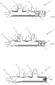
- Figure 1A illustrates the initial position of the three-way valve 1 according to the invention in which the first port 11 is open and the second port 12 is closed. In this position, the first windows 21, 31 of the first and second piston 2, 3 are facing the first orifice 11. The first windows 21, 31 of the first and second piston 2, 3 are aligned. The second windows 22, 32 of the first and second piston 2, 3 are offset from the second orifice 12.
- FIG. 1B represents an intermediate position of the three-way valve 1 in which the actuator has started to move the first piston 2 towards the open position of the second port 12.
- the first window 21 of the first piston 2 shifts and the first piston partially closes the first orifice 11.
- the second window 22 of the first piston 2 begins to align with the second orifice 12, then increasing the passage section of the second orifice 12.
- the second piston 3 obstructs part of the first window 21 of the first piston 2, then reducing the passage section of the first orifice 11 relative to the passage section of the second orifice 12.
- Figure 1C illustrates the final position of the three-way valve 1 according to the invention in which the first port 11 is closed and the second port 12 is open.
- the second windows 22, 32 of the first and second piston 2, 3 are opposite the second orifice 12.
- the second windows 22, 32 of the first and second piston 2, 3 are opposite screw from to the second port 12.
- the second windows 22, 32 of the first and second piston 2, 3 are aligned.
- Sealing elements (not shown) (of the seal or lip type) are positioned between the channel 13 and the first piston 2 and between the first piston 2 and the second piston 3 in order to prevent fluid leaks.
- the first and second elastic means are coil springs.
- the second piston 3 is replaced by a shutter 4.
- the shutter 4 is pivotally mounted on the edge of the first window 21 of the first piston 2.
- the shutter 4 is arranged to open or close the first window 21 of the first piston 2 during the movement of the first piston.
- the dimensions of the shutter 4 correspond to the dimensions of the first window 21 of the first piston 2.
- the pivoting of the shutter 4 is for example provided by a hinge 41 positioned on the edge of the first window 11 furthest from the inlet orifice 10 of the three-way valve 1.
- FIG 2A illustrates the initial position of the three-way valve 1 according to the invention in which the first port 11 is open and the second port 12 is closed.
- the shutter 4 enters the first orifice 11.
- the shutter 4 does not interfere with the flow of fluid in the first orifice 11.
- the second orifice 12 being closed by the first piston 1, the entire fluid flow passes through the first orifice 11.
- FIG. 2B represents an intermediate position of the three-way valve 1 in which the actuator has started to move the first piston 2 towards the open position of the second port 12.
- the shutter 4 is moved by the wall of the first orifice 11 to partially obstruct the first window 21 of the first piston.
- the junction between the wall of the orifice and the channel 13 of the three-way valve 1 may have a radius of curvature to ensure progressive pivoting of the shutter 4.
- the second window 22 of the first piston 2 begins to align with the second orifice 12 then increasing the passage section of the second orifice 12. However, in this position, the passage section of the first window 21 is reduced by the shutter 4 relative to the passage section of the second window 22. This difference in passage section in favor of the second window 22 makes it possible to balance the flow of fluid between the two orifices 11, 12 without modifying the flow entering the three-way valve. 1.
- FIG 1C illustrates the final position of the three-way valve 1 according to the invention in which the first port 11 is closed and the second port 12 is open.
- the shutter 4 is held in the closed position of the first window 21 by the wall of the channel 13.
- the second window 22 of the first piston 2 faces the second orifice 12. In this position, the entire flow passes through the second port 12.
- an assembly is rotation of the first piston 2 and / or of the second piston 3 is also possible.
Landscapes
- Engineering & Computer Science (AREA)
- General Engineering & Computer Science (AREA)
- Mechanical Engineering (AREA)
- Physics & Mathematics (AREA)
- Thermal Sciences (AREA)
- Chemical & Material Sciences (AREA)
- Combustion & Propulsion (AREA)
- Multiple-Way Valves (AREA)
Claims (7)
- Fluidkreislauf, der ein 3-Wege-Ventil (1) umfasst, das einen zentralen Kanal (13) umfasst, in den sich eine Einlassöffnung (10), eine erste Auslassöffnung (11) und eine zweite Auslassöffnung (12) öffnet, wobei das 3-Wege-Ventil ferner eine Einstellungsvorrichtung (2, 3, 4) umfasst, die gleichzeitig das Öffnen bzw. das Schließen der ersten Auslassöffnung (11) und das Schließen bzw. das Öffnen der zweiten Auslassöffnung (12) ermöglicht, so dass die Schließgeschwindigkeit der ersten Auslassöffnung (11) schneller ist als die Öffnungsgeschwindigkeit der zweiten Auslassöffnung (12), dadurch gekennzeichnet, dass der Fluidkreislauf ein Kühlkreislauf ist, der eine erste Komponente, die mit der ersten Auslassöffnung verbunden ist, und eine zweite Komponente umfasst, die mit der zweiten Auslassöffnung verbunden ist, wobei der durch die erste Komponente im 3-Wege-Ventil erzeugte Druckabfall niedriger ist als der durch die zweite Komponente im 3-Wege-Ventil erzeugte Druckabfall.
- Fluidkreislauf nach Anspruch 1, dadurch gekennzeichnet, dass die Einstellungsvorrichtung einen ersten Kolben (2) umfasst, der koaxial in dem zentralen Kanal (13) montiert ist, und der erste Kolben (2) ein erstes Fenster (21) und ein zweites Fenster (22) umfasst, wobei das erste (21) bzw. das zweite (22) Fenster so angeordnet sind, dass sie das Öffnen der ersten (11) bzw. der zweiten (12) Auslassöffnung ermöglichen, wobei das erste Fenster mit einem Verschluss (4) ausgestattet ist, der durch die Bewegung des ersten Kolbens (2) betätigt wird und eine mindestens teilweise Schließung der ersten Auslassöffnung (11) des 3-Wege-Ventils (1) ermöglicht.
- Fluidkreislauf nach Anspruch 1, dadurch gekennzeichnet, dass die Einstellungsvorrichtung einen ersten Kolben (2) umfasst, der koaxial in dem zentralen Kanal (13) montiert ist, und der erste Kolben ein erstes Fenster (21) und ein zweites Fenster (22) umfasst, wobei das erste (21) bzw. das zweite (22) Fenster so angeordnet sind, dass sie das Öffnen der ersten (11) bzw. der zweiten Auslassöffnung (12) ermöglichen, wobei die Einstellungsvorrichtung einen zweiten Kolben (3) umfasst, der koaxial in dem ersten Kolben (2) montiert ist, und der zweite Kolben (3) ein erstes Fenster (31) und ein zweites Fenster (32) umfasst, wobei das erste Fenster (31) des zweiten Kolbens (3) so angeordnet ist, dass es das erste Fenster (21) des ersten Kolbens (2) teilweise schließt, wenn die erste Auslassöffnung (11) von dem ersten Kolben (2) geschlossen wird.
- Fluidkreislauf nach Anspruch 2 oder 3, dadurch gekennzeichnet, dass der erste Kolben (2) gleitbar in dem zentralen Kanal (13) montiert ist und ein elastisches Rückführelement umfasst, das ihn in Richtung einer geschlossenen Position der zweiten Auslassöffnung vorspannt.
- Fluidkreislauf nach Anspruch 3, dadurch gekennzeichnet, dass der zweite Kolben (3) gleitbar in dem ersten Kolben (2) montiert ist und ein elastisches Element (5) zum Zurückführen in eine Position umfasst, die das erste Fenster (21) des ersten Kolbens (2) teilweise schließt.
- Fluidkreislauf nach einem der vorhergehenden Ansprüche, dadurch gekennzeichnet, dass das 3-Wege-Ventil einen Aktuator umfasst, der so angeordnet ist, dass er die Bewegung des ersten Kolbens (2) zwischen einer ersten Position, in der die erste Auslassöffnung (11) geschlossen ist und die zweite Auslassöffnung (12) offen ist, und einer zweiten Position, in der die erste Auslassöffnung (11) offen ist und die zweite Auslassöffnung (12) geschlossen ist, veranlasst.
- Fluidkreislauf nach einem der vorhergehenden Ansprüche, dadurch gekennzeichnet, dass der Fluidkreislauf ein Kühlkreislauf ist, der einen Wärmetauscher und einen Umgehungskreislauf des Wärmetauschers umfasst, wobei die erste Auslassöffnung mit dem Umgehungskreislauf des Wärmetauschers verbunden ist und die zweite Auslassöffnung mit dem Wärmetauscher verbunden ist.
Priority Applications (3)
| Application Number | Priority Date | Filing Date | Title |
|---|---|---|---|
| EP21305062.8A EP4030085B1 (de) | 2021-01-19 | 2021-01-19 | Fluidkreislauf für ein kraftfahrzeug |
| US17/456,438 US12188567B2 (en) | 2021-01-19 | 2021-11-24 | Fluid circuit comprising three way valve with adjustment device |
| CN202210016897.1A CN114876626A (zh) | 2021-01-19 | 2022-01-07 | 用于机动车辆的流体回路 |
Applications Claiming Priority (1)
| Application Number | Priority Date | Filing Date | Title |
|---|---|---|---|
| EP21305062.8A EP4030085B1 (de) | 2021-01-19 | 2021-01-19 | Fluidkreislauf für ein kraftfahrzeug |
Publications (2)
| Publication Number | Publication Date |
|---|---|
| EP4030085A1 EP4030085A1 (de) | 2022-07-20 |
| EP4030085B1 true EP4030085B1 (de) | 2024-11-06 |
Family
ID=74505152
Family Applications (1)
| Application Number | Title | Priority Date | Filing Date |
|---|---|---|---|
| EP21305062.8A Active EP4030085B1 (de) | 2021-01-19 | 2021-01-19 | Fluidkreislauf für ein kraftfahrzeug |
Country Status (3)
| Country | Link |
|---|---|
| US (1) | US12188567B2 (de) |
| EP (1) | EP4030085B1 (de) |
| CN (1) | CN114876626A (de) |
Families Citing this family (3)
| Publication number | Priority date | Publication date | Assignee | Title |
|---|---|---|---|---|
| EP4368933B1 (de) * | 2022-11-10 | 2025-06-11 | L'air Liquide, Societe Anonyme Pour L'etude Et L'exploitation Des Procedes Georges Claude | Regelvorrichtung zur regelung der temperatur eines prozessgases und wärmeaustauscher mit einer regelvorrichtung |
| CN116785903A (zh) * | 2023-07-28 | 2023-09-22 | 华能国际电力股份有限公司 | 一种酸雾报警应急装置及应急处理方法 |
| WO2025099657A1 (en) * | 2023-11-10 | 2025-05-15 | Fira S.P.A. | Heat exchange apparatus for working fluids in power machines |
Family Cites Families (9)
| Publication number | Priority date | Publication date | Assignee | Title |
|---|---|---|---|---|
| US3353590A (en) * | 1965-07-12 | 1967-11-21 | Holman And Moody Inc | Unitary oil filtering and cooling attachment for internal combustion engines |
| US3693663A (en) * | 1970-11-27 | 1972-09-26 | Price Pfister Brass Mfg | Mixing valve |
| US3985154A (en) * | 1975-10-24 | 1976-10-12 | Emerson Electric Co. | Four-way valve |
| US8127790B2 (en) * | 2009-03-25 | 2012-03-06 | Husco Automotive Holdings Llc | Hydraulic valve with a filter and check valve band |
| US8910661B2 (en) * | 2013-01-03 | 2014-12-16 | Emerson Process Management Regulator Technologies, Inc. | Valve sound reducing trim assembly with pressure relief mechanism |
| US10309544B2 (en) * | 2017-02-13 | 2019-06-04 | Cameron International Corporation | Valve assembly |
| BE1025334B1 (nl) * | 2017-06-21 | 2019-01-28 | Punch Powertrain Nv | Hydraulisch systeem |
| DE102019200940A1 (de) * | 2019-01-25 | 2020-07-30 | Robert Bosch Gmbh | Schnellschaltventil |
| CN109946052B (zh) * | 2019-02-27 | 2023-12-15 | 中国地质大学(北京) | 动力钻具水力部件工作性能测试装置 |
-
2021
- 2021-01-19 EP EP21305062.8A patent/EP4030085B1/de active Active
- 2021-11-24 US US17/456,438 patent/US12188567B2/en active Active
-
2022
- 2022-01-07 CN CN202210016897.1A patent/CN114876626A/zh active Pending
Also Published As
| Publication number | Publication date |
|---|---|
| CN114876626A (zh) | 2022-08-09 |
| US12188567B2 (en) | 2025-01-07 |
| EP4030085A1 (de) | 2022-07-20 |
| US20220228668A1 (en) | 2022-07-21 |
Similar Documents
| Publication | Publication Date | Title |
|---|---|---|
| US12188567B2 (en) | Fluid circuit comprising three way valve with adjustment device | |
| EP2864607B1 (de) | Flüssigkeitsmengenregler | |
| EP2864608B1 (de) | Kühlsystem für kraftfahrzeugmotor und verfahren | |
| US8973537B2 (en) | Engine having thermostat and system thereof | |
| US20100213401A1 (en) | Bypass valve for a cooler connected downstream of a hydraulic unit | |
| KR20030031953A (ko) | 비례 압력 조절 밸브 | |
| US20080223317A1 (en) | Cooling apparatus for internal combustion engine | |
| MX2014009486A (es) | Valvula para motor con derivacion de cera integrada a prueba de fallos. | |
| JP2018534480A (ja) | 流体供給システム | |
| US5690276A (en) | Two stage thermostatic valve device | |
| US8042745B2 (en) | Thermally responsive valve for regulating engine coolant flow | |
| US20200158001A1 (en) | Apparatus and method for controlling flow rate of engine coolant by use of a thermostat | |
| CN101278107A (zh) | 用于分离通过冷却器的油流动的装置 | |
| US20070079774A1 (en) | Cooling system for a combustion engine | |
| US10794263B2 (en) | Thermostat for engine cooling system | |
| US10538214B2 (en) | Controlled in-tank flow guide for heat exchanger | |
| EP2227646B1 (de) | Ventilanordnung | |
| US10215079B2 (en) | Thermostatic valve | |
| US20090114183A1 (en) | Transmission Thermostat Device | |
| US20100276613A1 (en) | Thermostatic device and related method | |
| EP3732356B1 (de) | Flüssigkeitskreislauf und verfahren zur steuerung eines zu mindestens einem gerät zugeführten flüssigkeitsstroms | |
| KR101694064B1 (ko) | 자동차용 오일 써모스탯 | |
| EP3521582B1 (de) | Verbinder | |
| EP4177448A1 (de) | Kühlsystem | |
| MX2007008682A (es) | Sello para valvula de mariposa e interruptor de paso. |
Legal Events
| Date | Code | Title | Description |
|---|---|---|---|
| PUAI | Public reference made under article 153(3) epc to a published international application that has entered the european phase |
Free format text: ORIGINAL CODE: 0009012 |
|
| STAA | Information on the status of an ep patent application or granted ep patent |
Free format text: STATUS: THE APPLICATION HAS BEEN PUBLISHED |
|
| AK | Designated contracting states |
Kind code of ref document: A1 Designated state(s): AL AT BE BG CH CY CZ DE DK EE ES FI FR GB GR HR HU IE IS IT LI LT LU LV MC MK MT NL NO PL PT RO RS SE SI SK SM TR |
|
| STAA | Information on the status of an ep patent application or granted ep patent |
Free format text: STATUS: REQUEST FOR EXAMINATION WAS MADE |
|
| 17P | Request for examination filed |
Effective date: 20221201 |
|
| RBV | Designated contracting states (corrected) |
Designated state(s): AL AT BE BG CH CY CZ DE DK EE ES FI FR GB GR HR HU IE IS IT LI LT LU LV MC MK MT NL NO PL PT RO RS SE SI SK SM TR |
|
| GRAP | Despatch of communication of intention to grant a patent |
Free format text: ORIGINAL CODE: EPIDOSNIGR1 |
|
| STAA | Information on the status of an ep patent application or granted ep patent |
Free format text: STATUS: GRANT OF PATENT IS INTENDED |
|
| GRAS | Grant fee paid |
Free format text: ORIGINAL CODE: EPIDOSNIGR3 |
|
| INTG | Intention to grant announced |
Effective date: 20240902 |
|
| GRAA | (expected) grant |
Free format text: ORIGINAL CODE: 0009210 |
|
| STAA | Information on the status of an ep patent application or granted ep patent |
Free format text: STATUS: THE PATENT HAS BEEN GRANTED |
|
| AK | Designated contracting states |
Kind code of ref document: B1 Designated state(s): AL AT BE BG CH CY CZ DE DK EE ES FI FR GB GR HR HU IE IS IT LI LT LU LV MC MK MT NL NO PL PT RO RS SE SI SK SM TR |
|
| REG | Reference to a national code |
Ref country code: GB Ref legal event code: FG4D |
|
| REG | Reference to a national code |
Ref country code: CH Ref legal event code: EP |
|
| REG | Reference to a national code |
Ref country code: DE Ref legal event code: R096 Ref document number: 602021021357 Country of ref document: DE |
|
| REG | Reference to a national code |
Ref country code: IE Ref legal event code: FG4D |
|
| REG | Reference to a national code |
Ref country code: LT Ref legal event code: MG9D |
|
| REG | Reference to a national code |
Ref country code: NL Ref legal event code: MP Effective date: 20241106 |
|
| PG25 | Lapsed in a contracting state [announced via postgrant information from national office to epo] |
Ref country code: PT Free format text: LAPSE BECAUSE OF FAILURE TO SUBMIT A TRANSLATION OF THE DESCRIPTION OR TO PAY THE FEE WITHIN THE PRESCRIBED TIME-LIMIT Effective date: 20250306 Ref country code: HR Free format text: LAPSE BECAUSE OF FAILURE TO SUBMIT A TRANSLATION OF THE DESCRIPTION OR TO PAY THE FEE WITHIN THE PRESCRIBED TIME-LIMIT Effective date: 20241106 Ref country code: IS Free format text: LAPSE BECAUSE OF FAILURE TO SUBMIT A TRANSLATION OF THE DESCRIPTION OR TO PAY THE FEE WITHIN THE PRESCRIBED TIME-LIMIT Effective date: 20250306 |
|
| PG25 | Lapsed in a contracting state [announced via postgrant information from national office to epo] |
Ref country code: NL Free format text: LAPSE BECAUSE OF FAILURE TO SUBMIT A TRANSLATION OF THE DESCRIPTION OR TO PAY THE FEE WITHIN THE PRESCRIBED TIME-LIMIT Effective date: 20241106 Ref country code: FI Free format text: LAPSE BECAUSE OF FAILURE TO SUBMIT A TRANSLATION OF THE DESCRIPTION OR TO PAY THE FEE WITHIN THE PRESCRIBED TIME-LIMIT Effective date: 20241106 |
|
| REG | Reference to a national code |
Ref country code: AT Ref legal event code: MK05 Ref document number: 1739665 Country of ref document: AT Kind code of ref document: T Effective date: 20241106 |
|
| PG25 | Lapsed in a contracting state [announced via postgrant information from national office to epo] |
Ref country code: BG Free format text: LAPSE BECAUSE OF FAILURE TO SUBMIT A TRANSLATION OF THE DESCRIPTION OR TO PAY THE FEE WITHIN THE PRESCRIBED TIME-LIMIT Effective date: 20241106 |
|
| PG25 | Lapsed in a contracting state [announced via postgrant information from national office to epo] |
Ref country code: ES Free format text: LAPSE BECAUSE OF FAILURE TO SUBMIT A TRANSLATION OF THE DESCRIPTION OR TO PAY THE FEE WITHIN THE PRESCRIBED TIME-LIMIT Effective date: 20241106 |
|
| PG25 | Lapsed in a contracting state [announced via postgrant information from national office to epo] |
Ref country code: NO Free format text: LAPSE BECAUSE OF FAILURE TO SUBMIT A TRANSLATION OF THE DESCRIPTION OR TO PAY THE FEE WITHIN THE PRESCRIBED TIME-LIMIT Effective date: 20250206 |
|
| PG25 | Lapsed in a contracting state [announced via postgrant information from national office to epo] |
Ref country code: GR Free format text: LAPSE BECAUSE OF FAILURE TO SUBMIT A TRANSLATION OF THE DESCRIPTION OR TO PAY THE FEE WITHIN THE PRESCRIBED TIME-LIMIT Effective date: 20250207 Ref country code: LV Free format text: LAPSE BECAUSE OF FAILURE TO SUBMIT A TRANSLATION OF THE DESCRIPTION OR TO PAY THE FEE WITHIN THE PRESCRIBED TIME-LIMIT Effective date: 20241106 Ref country code: AT Free format text: LAPSE BECAUSE OF FAILURE TO SUBMIT A TRANSLATION OF THE DESCRIPTION OR TO PAY THE FEE WITHIN THE PRESCRIBED TIME-LIMIT Effective date: 20241106 |
|
| PG25 | Lapsed in a contracting state [announced via postgrant information from national office to epo] |
Ref country code: PL Free format text: LAPSE BECAUSE OF FAILURE TO SUBMIT A TRANSLATION OF THE DESCRIPTION OR TO PAY THE FEE WITHIN THE PRESCRIBED TIME-LIMIT Effective date: 20241106 |
|
| PG25 | Lapsed in a contracting state [announced via postgrant information from national office to epo] |
Ref country code: RS Free format text: LAPSE BECAUSE OF FAILURE TO SUBMIT A TRANSLATION OF THE DESCRIPTION OR TO PAY THE FEE WITHIN THE PRESCRIBED TIME-LIMIT Effective date: 20250206 |
|
| PG25 | Lapsed in a contracting state [announced via postgrant information from national office to epo] |
Ref country code: SM Free format text: LAPSE BECAUSE OF FAILURE TO SUBMIT A TRANSLATION OF THE DESCRIPTION OR TO PAY THE FEE WITHIN THE PRESCRIBED TIME-LIMIT Effective date: 20241106 |
|
| PG25 | Lapsed in a contracting state [announced via postgrant information from national office to epo] |
Ref country code: DK Free format text: LAPSE BECAUSE OF FAILURE TO SUBMIT A TRANSLATION OF THE DESCRIPTION OR TO PAY THE FEE WITHIN THE PRESCRIBED TIME-LIMIT Effective date: 20241106 |
|
| PG25 | Lapsed in a contracting state [announced via postgrant information from national office to epo] |
Ref country code: EE Free format text: LAPSE BECAUSE OF FAILURE TO SUBMIT A TRANSLATION OF THE DESCRIPTION OR TO PAY THE FEE WITHIN THE PRESCRIBED TIME-LIMIT Effective date: 20241106 |
|
| PG25 | Lapsed in a contracting state [announced via postgrant information from national office to epo] |
Ref country code: RO Free format text: LAPSE BECAUSE OF FAILURE TO SUBMIT A TRANSLATION OF THE DESCRIPTION OR TO PAY THE FEE WITHIN THE PRESCRIBED TIME-LIMIT Effective date: 20241106 |
|
| PG25 | Lapsed in a contracting state [announced via postgrant information from national office to epo] |
Ref country code: SK Free format text: LAPSE BECAUSE OF FAILURE TO SUBMIT A TRANSLATION OF THE DESCRIPTION OR TO PAY THE FEE WITHIN THE PRESCRIBED TIME-LIMIT Effective date: 20241106 |
|
| PG25 | Lapsed in a contracting state [announced via postgrant information from national office to epo] |
Ref country code: CZ Free format text: LAPSE BECAUSE OF FAILURE TO SUBMIT A TRANSLATION OF THE DESCRIPTION OR TO PAY THE FEE WITHIN THE PRESCRIBED TIME-LIMIT Effective date: 20241106 |
|
| PG25 | Lapsed in a contracting state [announced via postgrant information from national office to epo] |
Ref country code: IT Free format text: LAPSE BECAUSE OF FAILURE TO SUBMIT A TRANSLATION OF THE DESCRIPTION OR TO PAY THE FEE WITHIN THE PRESCRIBED TIME-LIMIT Effective date: 20241106 |
|
| REG | Reference to a national code |
Ref country code: DE Ref legal event code: R097 Ref document number: 602021021357 Country of ref document: DE |
|
| REG | Reference to a national code |
Ref country code: CH Ref legal event code: PL |
|
| PG25 | Lapsed in a contracting state [announced via postgrant information from national office to epo] |
Ref country code: SE Free format text: LAPSE BECAUSE OF FAILURE TO SUBMIT A TRANSLATION OF THE DESCRIPTION OR TO PAY THE FEE WITHIN THE PRESCRIBED TIME-LIMIT Effective date: 20241106 |
|
| PLBE | No opposition filed within time limit |
Free format text: ORIGINAL CODE: 0009261 |
|
| STAA | Information on the status of an ep patent application or granted ep patent |
Free format text: STATUS: NO OPPOSITION FILED WITHIN TIME LIMIT |
|
| PG25 | Lapsed in a contracting state [announced via postgrant information from national office to epo] |
Ref country code: LU Free format text: LAPSE BECAUSE OF NON-PAYMENT OF DUE FEES Effective date: 20250119 Ref country code: MC Free format text: LAPSE BECAUSE OF FAILURE TO SUBMIT A TRANSLATION OF THE DESCRIPTION OR TO PAY THE FEE WITHIN THE PRESCRIBED TIME-LIMIT Effective date: 20241106 |
|
| 26N | No opposition filed |
Effective date: 20250807 |
|
| PG25 | Lapsed in a contracting state [announced via postgrant information from national office to epo] |
Ref country code: BE Free format text: LAPSE BECAUSE OF NON-PAYMENT OF DUE FEES Effective date: 20250131 |
|
| PG25 | Lapsed in a contracting state [announced via postgrant information from national office to epo] |
Ref country code: CH Free format text: LAPSE BECAUSE OF NON-PAYMENT OF DUE FEES Effective date: 20250131 |
|
| REG | Reference to a national code |
Ref country code: BE Ref legal event code: MM Effective date: 20250131 |
|
| GBPC | Gb: european patent ceased through non-payment of renewal fee |
Effective date: 20250206 |
|
| PG25 | Lapsed in a contracting state [announced via postgrant information from national office to epo] |
Ref country code: GB Free format text: LAPSE BECAUSE OF NON-PAYMENT OF DUE FEES Effective date: 20250206 |
|
| PG25 | Lapsed in a contracting state [announced via postgrant information from national office to epo] |
Ref country code: IE Free format text: LAPSE BECAUSE OF NON-PAYMENT OF DUE FEES Effective date: 20250119 |
|
| PGFP | Annual fee paid to national office [announced via postgrant information from national office to epo] |
Ref country code: DE Payment date: 20260127 Year of fee payment: 6 |
|
| PGFP | Annual fee paid to national office [announced via postgrant information from national office to epo] |
Ref country code: FR Payment date: 20260126 Year of fee payment: 6 |