EP4030106A1 - Système de filtre d'appareil d'aéronef - Google Patents
Système de filtre d'appareil d'aéronef Download PDFInfo
- Publication number
- EP4030106A1 EP4030106A1 EP22150990.4A EP22150990A EP4030106A1 EP 4030106 A1 EP4030106 A1 EP 4030106A1 EP 22150990 A EP22150990 A EP 22150990A EP 4030106 A1 EP4030106 A1 EP 4030106A1
- Authority
- EP
- European Patent Office
- Prior art keywords
- filter
- appliance
- slot
- cover
- control panel
- Prior art date
- Legal status (The legal status is an assumption and is not a legal conclusion. Google has not performed a legal analysis and makes no representation as to the accuracy of the status listed.)
- Pending
Links
Images


Classifications
-
- F—MECHANICAL ENGINEERING; LIGHTING; HEATING; WEAPONS; BLASTING
- F24—HEATING; RANGES; VENTILATING
- F24C—DOMESTIC STOVES OR RANGES ; DETAILS OF DOMESTIC STOVES OR RANGES, OF GENERAL APPLICATION
- F24C15/00—Details
- F24C15/20—Removing cooking fumes
- F24C15/2035—Arrangement or mounting of filters
-
- F—MECHANICAL ENGINEERING; LIGHTING; HEATING; WEAPONS; BLASTING
- F24—HEATING; RANGES; VENTILATING
- F24C—DOMESTIC STOVES OR RANGES ; DETAILS OF DOMESTIC STOVES OR RANGES, OF GENERAL APPLICATION
- F24C15/00—Details
- F24C15/20—Removing cooking fumes
- F24C15/2007—Removing cooking fumes from oven cavities
-
- F—MECHANICAL ENGINEERING; LIGHTING; HEATING; WEAPONS; BLASTING
- F25—REFRIGERATION OR COOLING; COMBINED HEATING AND REFRIGERATION SYSTEMS; HEAT PUMP SYSTEMS; MANUFACTURE OR STORAGE OF ICE; LIQUEFACTION SOLIDIFICATION OF GASES
- F25D—REFRIGERATORS; COLD ROOMS; ICE-BOXES; COOLING OR FREEZING APPARATUS NOT OTHERWISE PROVIDED FOR
- F25D23/00—General constructional features
- F25D23/12—Arrangements of compartments additional to cooling compartments; Combinations of refrigerators with other equipment, e.g. stove
-
- F—MECHANICAL ENGINEERING; LIGHTING; HEATING; WEAPONS; BLASTING
- F25—REFRIGERATION OR COOLING; COMBINED HEATING AND REFRIGERATION SYSTEMS; HEAT PUMP SYSTEMS; MANUFACTURE OR STORAGE OF ICE; LIQUEFACTION SOLIDIFICATION OF GASES
- F25D—REFRIGERATORS; COLD ROOMS; ICE-BOXES; COOLING OR FREEZING APPARATUS NOT OTHERWISE PROVIDED FOR
- F25D29/00—Arrangement or mounting of control or safety devices
- F25D29/005—Mounting of control devices
-
- B—PERFORMING OPERATIONS; TRANSPORTING
- B64—AIRCRAFT; AVIATION; COSMONAUTICS
- B64D—EQUIPMENT FOR FITTING IN OR TO AIRCRAFT; FLIGHT SUITS; PARACHUTES; ARRANGEMENT OR MOUNTING OF POWER PLANTS OR PROPULSION TRANSMISSIONS IN AIRCRAFT
- B64D11/00—Passenger or crew accommodation; Flight-deck installations not otherwise provided for
- B64D11/04—Galleys
-
- F—MECHANICAL ENGINEERING; LIGHTING; HEATING; WEAPONS; BLASTING
- F24—HEATING; RANGES; VENTILATING
- F24C—DOMESTIC STOVES OR RANGES ; DETAILS OF DOMESTIC STOVES OR RANGES, OF GENERAL APPLICATION
- F24C15/00—Details
- F24C15/30—Arrangements for mounting stoves or ranges in particular locations
-
- F—MECHANICAL ENGINEERING; LIGHTING; HEATING; WEAPONS; BLASTING
- F25—REFRIGERATION OR COOLING; COMBINED HEATING AND REFRIGERATION SYSTEMS; HEAT PUMP SYSTEMS; MANUFACTURE OR STORAGE OF ICE; LIQUEFACTION SOLIDIFICATION OF GASES
- F25D—REFRIGERATORS; COLD ROOMS; ICE-BOXES; COOLING OR FREEZING APPARATUS NOT OTHERWISE PROVIDED FOR
- F25D2323/00—General constructional features not provided for in other groups of this subclass
- F25D2323/002—Details for cooling refrigerating machinery
- F25D2323/0024—Filters in the air flow cooling refrigerating machinery
Definitions
- the present disclosure relates to an appliance filter system, and more particularly to an aircraft appliance having a single-piece fixated front panel.
- the appliances typically have a front access door and a control panel placed above the access door.
- appliances have employed removable control panels which allowed access to appliance insides including filter compartments allowing a user to easily access and service the filters.
- some modern appliances employ a control interface that may not be removable, and can take up the entire width of the appliances leaving a user no way to easily access and service the filters. Accordingly, there is a need in the art for an appliance having improved filter access and improved ease of service. There also remains a need in the art for such a system and components that are economically viable.
- the present disclosure may provide a solution for at least one of these remaining challenges.
- An appliance including a door configured to enclose a cooking or chilling space, a filter slot positioned above the door configured to accept a filter for filtering particles, and a control panel for controlling the appliance positioned above the door.
- the filter slot can be directed along a diagonal axis with respect to a vertical position defined by a vertical axis of the appliance.
- the control panel can include, user interface integrated into the front panel, which can also include a touch screen.
- the control panel can include a width equal to or greater than a majority of an appliance width.
- An air inlet can be adjacent to the user interface.
- the filter slot can be positioned below the control panel, wherein the filter is inserted at an upward angle.
- the filter slot can define a straight line from an opening slot to an inner terminus.
- the filter slot can include a guide rail configured to support the filter.
- the filter slot can define a curve along a path from the opening slot to an inner terminus.
- the opening slot can extend along a vertical axis along an edge of the front panel.
- the filter slot can include a latch configured to lock a filter in place.
- a filter cartridge can be included in order to retain a filter.
- the cartridge can be configured to rotate and discharge a filter section into the filter slot. As the filter is used up or discharged, the excess or expended filter material can be disposed. It is also considered that a dual cartridge system can be used, where one roll unwinds the new filter material and another roll collects the expended filter material.
- the appliance can be an oven or a refrigerator.
- a standalone filter assembly for use with the oven or refrigerators also disclosed.
- the filter can include a first cover, a filter insert placed on top of the first cover, and a second cover configured to lockably couple to the first cover and lock the filter inset with between the first cover and the second cover.
- the filter insert can includes a cloth material.
- the filter can include a filter cassette coupled to at least one of the covers in order to o retain multiple filter inserts detachably coupled to each other.
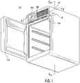
- FIG. 1 a partial view of an exemplary embodiment of a filter system in accordance with the invention is shown in Fig. 1 and is designated generally by reference character 100.
- Other embodiments of the system in accordance with the invention, or aspects thereof, are provided in Figs. 2-5 , as will be described.
- the methods and systems of the invention can be used to provide a filter system to appliances with a non-removable front panel.
- Fig. 1 shows a perspective view of an appliance 100 for use in an aircraft galley system.
- the appliance is considered to be an oven, a chiller, or similar.
- the appliance 100 includes a door 102 configured to enclose a cooking or chilling space, a filter slot 104 positioned above the door 102 which accepts a filter for filtering cooking particles.
- a control panel 106 for controlling the appliance is also positioned above the door 106.
- the control panel 106 includes, user interface 108 integrated into the front face 107 of the appliance, which can also include a touch screen.
- the control panel 106 can include a width equal to or greater than a majority of an appliance width.
- An air inlet 110 can be adjacent to the user interface.
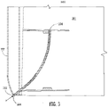
- Fig. 2 shows a cut-away view of the appliance 100 showing an area 101 inside of the appliance behind the face 107 and the filter slot 104.
- the filter slot 104 is directed along a diagonal axis 105 with respect to a vertical a vertical axis 108 of the appliance 100. The angled insertion of the filter allows to increase the effective filter surface without having to extend the filter too much further.
- the filter slot 104 is positioned below the control panel 106 forcing the filter to be inserted at an upward angle (a) with respect to the horizontal.
- the filter slot 104 can define a straight line from an opening slot 112 to an inner terminus 114.
- the filter slot 104 includes a guide rail 115 to support and guide the filter along the slot.
- the filter slot 104 can include a latch 116 to lock a filter in place at the opening slot 112.
- Fig. 3 shows a top down cut-away view of the appliance 300 showing an area 301 inside of the appliance behind the face 107.
- the filter slot 304 defines a curve along a path from the opening slot 312 to an inner terminus 314.
- the opening slot 312 extends along a vertical axis along an edge of the face 107. It is considered that both configurations shown can include a curved or straight filter slot.
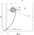
- Fig. 4 shows a top-down cut-away view of the appliance 400 showing an area inside of the appliance behind the from face 107 and the filter slot 404.
- the filter slot 404 leads to a filter cartridge 418.
- the cartridge includes a drum 420 having a preloaded plurality of filters.
- Each of the filters are attached to each other, possibly by a perforated connection 417 in a roll configuration.
- a user can pull on the filter, causing the drum to rotate in order to change the filter and service the appliance 400.
- This configuration allows for a less invasive and less frequent service of the filter system.
- a dual cartridge system can be employed where as a first roll unwinds new filter material a second roll collects the expended filter material.
- Fig. 5 shows a standalone filter assembly 500 for use with the oven or refrigerator is disclosed.
- the filter assembly 500 includes a first cover 502, a filter insert 504 placed on top of the first cover 502, and a second cover configured 506 to lockably couple to the first cover 502 and lock the filter inset 504.
- the filter insert 504 can includes a cloth material, as can the filters of the previous embodiments.
Landscapes
- Engineering & Computer Science (AREA)
- General Engineering & Computer Science (AREA)
- Combustion & Propulsion (AREA)
- Chemical & Material Sciences (AREA)
- Mechanical Engineering (AREA)
- Physics & Mathematics (AREA)
- Thermal Sciences (AREA)
- Aviation & Aerospace Engineering (AREA)
- Cold Air Circulating Systems And Constructional Details In Refrigerators (AREA)
- Health & Medical Sciences (AREA)
- General Health & Medical Sciences (AREA)
- Pulmonology (AREA)
- Filtering Of Dispersed Particles In Gases (AREA)
Applications Claiming Priority (1)
| Application Number | Priority Date | Filing Date | Title |
|---|---|---|---|
| US17/148,510 US12103687B2 (en) | 2021-01-13 | 2021-01-13 | Aircraft appliance filter system |
Publications (1)
| Publication Number | Publication Date |
|---|---|
| EP4030106A1 true EP4030106A1 (fr) | 2022-07-20 |
Family
ID=79317012
Family Applications (1)
| Application Number | Title | Priority Date | Filing Date |
|---|---|---|---|
| EP22150990.4A Pending EP4030106A1 (fr) | 2021-01-13 | 2022-01-11 | Système de filtre d'appareil d'aéronef |
Country Status (2)
| Country | Link |
|---|---|
| US (2) | US12103687B2 (fr) |
| EP (1) | EP4030106A1 (fr) |
Families Citing this family (1)
| Publication number | Priority date | Publication date | Assignee | Title |
|---|---|---|---|---|
| US20220205645A1 (en) * | 2020-12-28 | 2022-06-30 | Koninklijke Fabriek Inventum B.V. | Hydrophobic filter in oven air oulet |
Citations (7)
| Publication number | Priority date | Publication date | Assignee | Title |
|---|---|---|---|---|
| FR2123751A5 (fr) * | 1971-01-29 | 1972-09-15 | Coste Caumartin Ets | |
| DE2347586A1 (de) * | 1973-09-21 | 1975-04-10 | Sueddeutsche Metallwerke Gmbh | Dunstabzugs- und filtervorrichtung |
| CH630240A5 (en) * | 1978-06-22 | 1982-06-15 | Electrolux Ag | Hot-air circulating, baking, frying and grilling oven, and method of operating it |
| DE102005019957A1 (de) * | 2005-04-29 | 2006-11-09 | Electrolux Home Products Corporation N.V. | Garofen |
| KR100782706B1 (ko) * | 2006-05-02 | 2007-12-07 | 백세정 | 유아용 복합기 |
| WO2017029037A1 (fr) * | 2015-08-18 | 2017-02-23 | MKN Maschinenfabrik Kurt Neubauer GmbH & Co. KG | Hotte aspirante pour un appareil de cuisson, ainsi qu'appareil de cuisson équipé d'une hotte aspirante de ce type |
| CN207050040U (zh) * | 2017-08-07 | 2018-02-27 | 樱花卫厨(中国)股份有限公司 | 方便更换滤油网的侧吸式抽油烟机 |
Family Cites Families (10)
| Publication number | Priority date | Publication date | Assignee | Title |
|---|---|---|---|---|
| DE2832864C3 (de) | 1978-07-26 | 1981-04-30 | Markus 8351 Aholming Schmalhofer | Filter zur Ausfilterung von fettartigen Teilchen aus einem Gasstrom, insbesondere aus Küchenabluft, sowie Abluftkanal hierfür |
| DE102009052993B4 (de) | 2009-11-12 | 2017-11-23 | Airbus Operations Gmbh | Küchengerät für ein Flugzeug |
| JP5911430B2 (ja) * | 2010-01-13 | 2016-04-27 | オーワイ ハルトン グループ リミテッド | 排気装置 |
| KR101103031B1 (ko) * | 2010-07-13 | 2012-01-05 | 강연균 | 냉장 시약장 |
| US20180016012A1 (en) * | 2016-07-12 | 2018-01-18 | B/E Aerospace, Inc. | System, Methods, and Apparatus for Air Flow Handling in an Aircraft Monument |
| CN107781886B (zh) * | 2017-11-27 | 2019-07-19 | 杨肇 | 一种零和式低碳油烟净化器及净化系统 |
| KR102487212B1 (ko) | 2018-02-05 | 2023-01-11 | 엘지전자 주식회사 | 공기처리장치가 구비된 냉장고 |
| DE202019100108U1 (de) | 2019-01-10 | 2020-04-15 | MKN Maschinenfabrik Kurt Neubauer GmbH & Co. KG | Kombidämpfer mit wenigstens zwei Gareinheiten und einer Dunstabzugshaube |
| DE102019205337A1 (de) * | 2019-04-12 | 2020-10-15 | Wilhelm Bruckbauer | Vorrichtung zum Erhitzen von Gargut |
| US11522275B2 (en) * | 2020-12-22 | 2022-12-06 | B/E Aerospace, Inc | Aircraft inserts having surface integrated antennas and/or filters |
-
2021
- 2021-01-13 US US17/148,510 patent/US12103687B2/en active Active
-
2022
- 2022-01-11 EP EP22150990.4A patent/EP4030106A1/fr active Pending
-
2024
- 2024-08-27 US US18/816,450 patent/US20240417077A1/en active Pending
Patent Citations (7)
| Publication number | Priority date | Publication date | Assignee | Title |
|---|---|---|---|---|
| FR2123751A5 (fr) * | 1971-01-29 | 1972-09-15 | Coste Caumartin Ets | |
| DE2347586A1 (de) * | 1973-09-21 | 1975-04-10 | Sueddeutsche Metallwerke Gmbh | Dunstabzugs- und filtervorrichtung |
| CH630240A5 (en) * | 1978-06-22 | 1982-06-15 | Electrolux Ag | Hot-air circulating, baking, frying and grilling oven, and method of operating it |
| DE102005019957A1 (de) * | 2005-04-29 | 2006-11-09 | Electrolux Home Products Corporation N.V. | Garofen |
| KR100782706B1 (ko) * | 2006-05-02 | 2007-12-07 | 백세정 | 유아용 복합기 |
| WO2017029037A1 (fr) * | 2015-08-18 | 2017-02-23 | MKN Maschinenfabrik Kurt Neubauer GmbH & Co. KG | Hotte aspirante pour un appareil de cuisson, ainsi qu'appareil de cuisson équipé d'une hotte aspirante de ce type |
| CN207050040U (zh) * | 2017-08-07 | 2018-02-27 | 樱花卫厨(中国)股份有限公司 | 方便更换滤油网的侧吸式抽油烟机 |
Also Published As
| Publication number | Publication date |
|---|---|
| US20220219823A1 (en) | 2022-07-14 |
| US20240417077A1 (en) | 2024-12-19 |
| US12103687B2 (en) | 2024-10-01 |
Similar Documents
| Publication | Publication Date | Title |
|---|---|---|
| KR102804546B1 (ko) | 냉장고 | |
| US20240417077A1 (en) | Aircraft appliance filter system | |
| US5499514A (en) | Defrost water drain system for a refrigerator | |
| US9115903B2 (en) | Oven door | |
| US2434117A (en) | Shelf structure with guard for refrigerator doors | |
| KR102305968B1 (ko) | 하향 환기장치를 위한 인서트 | |
| EP3309463A1 (fr) | Four | |
| EP3479027B1 (fr) | Appareil de cuisson | |
| US2708709A (en) | Domestic appliance | |
| GB2361521A (en) | Refrigerated display cabinet | |
| CN110547043A (zh) | 用于烤箱支撑结构和空气过滤组装件的装置和系统 | |
| US10260756B2 (en) | Deflecting element for appliance doors | |
| US11009235B2 (en) | Domestic kitchen appliance with sidewall cooling | |
| US20210025641A1 (en) | Refrigerator assembly having features for improved air circulation through a machine compartment thereof | |
| JP2017215119A (ja) | 冷蔵庫 | |
| EP3249307A1 (fr) | Hotte d'extraction/filtrage de type amélioré pour cuisines | |
| US20190277511A1 (en) | Flue for cooking appliance | |
| RU2419748C2 (ru) | Встроенная электроплита | |
| EP2921804A1 (fr) | Appareil frigorifique avec système de circulation d'air amélioré | |
| KR102153136B1 (ko) | 냉장고 | |
| JP2017215117A (ja) | 冷蔵庫 | |
| KR100780833B1 (ko) | 냉장고용 디스펜서의 급수탱크 장착구조 | |
| CN223564359U (zh) | 厨房空调 | |
| US2774225A (en) | Refrigerated food display cabinets | |
| GB2186964A (en) | Combined vapour extractor and cupboard unit |
Legal Events
| Date | Code | Title | Description |
|---|---|---|---|
| PUAI | Public reference made under article 153(3) epc to a published international application that has entered the european phase |
Free format text: ORIGINAL CODE: 0009012 |
|
| STAA | Information on the status of an ep patent application or granted ep patent |
Free format text: STATUS: THE APPLICATION HAS BEEN PUBLISHED |
|
| AK | Designated contracting states |
Kind code of ref document: A1 Designated state(s): AL AT BE BG CH CY CZ DE DK EE ES FI FR GB GR HR HU IE IS IT LI LT LU LV MC MK MT NL NO PL PT RO RS SE SI SK SM TR |
|
| STAA | Information on the status of an ep patent application or granted ep patent |
Free format text: STATUS: REQUEST FOR EXAMINATION WAS MADE |
|
| 17P | Request for examination filed |
Effective date: 20230119 |
|
| RBV | Designated contracting states (corrected) |
Designated state(s): AL AT BE BG CH CY CZ DE DK EE ES FI FR GB GR HR HU IE IS IT LI LT LU LV MC MK MT NL NO PL PT RO RS SE SI SK SM TR |
|
| STAA | Information on the status of an ep patent application or granted ep patent |
Free format text: STATUS: EXAMINATION IS IN PROGRESS |
|
| 17Q | First examination report despatched |
Effective date: 20240416 |
|
| RAP1 | Party data changed (applicant data changed or rights of an application transferred) |
Owner name: B/E AEROSPACE INC. |
|
| RIC1 | Information provided on ipc code assigned before grant |
Ipc: F24C 15/20 20060101AFI20260312BHEP Ipc: F25D 23/12 20060101ALI20260312BHEP Ipc: F25D 29/00 20060101ALI20260312BHEP Ipc: F24C 15/30 20060101ALN20260312BHEP Ipc: B64D 11/04 20060101ALN20260312BHEP |
|
| GRAP | Despatch of communication of intention to grant a patent |
Free format text: ORIGINAL CODE: EPIDOSNIGR1 |
|
| STAA | Information on the status of an ep patent application or granted ep patent |
Free format text: STATUS: GRANT OF PATENT IS INTENDED |