EP4030199B1 - Unité inductive de détection de proximité et procédé de détermination d'une propriété d'objet d'un corps métallique de détection - Google Patents
Unité inductive de détection de proximité et procédé de détermination d'une propriété d'objet d'un corps métallique de détection Download PDFInfo
- Publication number
- EP4030199B1 EP4030199B1 EP22000001.2A EP22000001A EP4030199B1 EP 4030199 B1 EP4030199 B1 EP 4030199B1 EP 22000001 A EP22000001 A EP 22000001A EP 4030199 B1 EP4030199 B1 EP 4030199B1
- Authority
- EP
- European Patent Office
- Prior art keywords
- detection body
- time series
- series signal
- values
- metallic
- Prior art date
- Legal status (The legal status is an assumption and is not a legal conclusion. Google has not performed a legal analysis and makes no representation as to the accuracy of the status listed.)
- Active
Links
Images


Classifications
-
- G—PHYSICS
- G01—MEASURING; TESTING
- G01V—GEOPHYSICS; GRAVITATIONAL MEASUREMENTS; DETECTING MASSES OR OBJECTS; TAGS
- G01V3/00—Electric or magnetic prospecting or detecting; Measuring magnetic field characteristics of the earth, e.g. declination, deviation
- G01V3/08—Electric or magnetic prospecting or detecting; Measuring magnetic field characteristics of the earth, e.g. declination, deviation operating with magnetic or electric fields produced or modified by objects or geological structures or by detecting devices
- G01V3/10—Electric or magnetic prospecting or detecting; Measuring magnetic field characteristics of the earth, e.g. declination, deviation operating with magnetic or electric fields produced or modified by objects or geological structures or by detecting devices using induction coils
Definitions
- the invention relates to an inductive proximity sensor unit for detecting a detection body with metallic properties and a method for determining an object property of a metallic detection body with an inductive proximity sensor unit.
- an inductive sensor For detecting a material and/or shape parameter of a metal object, an inductive sensor is proposed, the transmitter coil of which, excited by square-wave driver pulses, induces eddy currents in the metal object, the secondary magnetic field of which is detected by a magnetic field sensor.
- the response signal from the magnetic field sensor is only evaluated during the duration of the square-wave driver pulses exciting the transmitter coil.
- the magnetic field sensor is connected to an evaluation circuit which evaluates a response signal dependent on the secondary magnetic field of the eddy currents and compares it with reference values stored in a memory.
- the values of a reference object are measured and stored in a reference position as reference values. In this way, surface hardness levels of metal components and their deviation from a reference value can be recorded.
- Metal objects can also be classified according to the type of metal, such as non-ferrous metal, steel or stainless steel.
- the transmitter coil is excited with a sequence of rectangular pulses and the resulting response signals from the magnetic field sensor are fed to the evaluation circuit.
- the signal curve of the response signal is evaluated with regard to extreme values and/or zero values as well as amplitude values at predetermined times.
- the evaluation circuit forms difference values from the recorded values and the stored reference values. The difference values are compared with limit values and/or threshold windows for determining a material and/or shape parameter.
- a detection coil of a proximity sensor is constructed according to the DE 10 2017 130 122 A1 is subjected to square-wave pulses and the impulse response is recorded in the form of a time series signal by means of a receiving circuit and evaluated by a controller with a control circuit and a calculation circuit.
- the first impulse response is divided into different time ranges based on the rising edge of the square-wave pulse.
- the shape of the impulse response is dominated by the inductance of the detection coil
- a second time range following the first time range the shape of the impulse response is dominated by the magnetic field of the detection body
- a third time range following the second time range Time range in which the impulse response has decayed, the shape of the impulse response is determined by the ohmic resistance of the detection coil.
- the impulse response is sampled and corresponding sample values are recorded.
- the second impulse response is evaluated after the end of the square-wave pulse, i.e. with its falling edge, with regard to a first, second and third time range.
- the sample values in the respective time ranges of the two successive impulse responses correlate with one another. Therefore, the samples of the second impulse response are corrected with a compensation coefficient.
- These compensation coefficients are generated by comparing the samples of the first impulse response with stored reference values. The presence or position of a detection body is detected using the corrected sample values of the second impulse response.
- an inductive proximity sensor for detecting a metallic object with a sensor coil wherein the sensor coil is supplied with a current for a first time interval and the impulse response at the sensor coil is detected in a second time interval and is evaluated.
- Another inductive sensor unit that works according to the pulse evaluation method is from the DE 10 2017 130 122 A1 known, whereby temperature-related changes in inductance and effective resistance are compensated.
- the current or the voltage at the sensor coil is already sampled during the excitation period when the sensor coil is subjected to the excitation current. Determined changes are used to compensate for an impulse response signal sampled during the blocking period to determine distance.
- Further sensor devices are from the DE 195 30 987 C1 ; the DE 10 2013 209 805 A1 and the DE 10 2009 058 549 A1 known.
- the object of the invention is to provide a device that advances the prior art
- an inductive proximity sensor unit for detecting a detection body, the detection body having metallic properties, is provided.
- the inductive proximity sensor unit has a sensor coil supplied with individual pulse-shaped signals spaced apart in time, an evaluation unit and a storage unit.
- the evaluation unit is designed to measure values for voltage or current of the pulse-shaped signal at several sampling times and to determine an actual time series signal from the measured values.
- At least three values of a reference time series signal are stored in the storage unit for the detection body.
- the evaluation unit is also designed to use an evaluation curve to determine a functional relationship between the actual time series signal and the reference time series signal and to check the functional relationship.
- a method for determining an object property of a metallic detection body with an inductive proximity sensor unit is provided.
- the proximity sensor unit has a sensor coil, a control circuit, a receiving circuit, a storage unit and an evaluation unit.
- the sensor coil is subjected to pulse-shaped signals that are spaced apart in time.
- a pulse-shaped excitation signal is applied to the sensor coil.
- values for the voltage or current are measured at several sampling times using the control circuit.
- the evaluation unit determines an actual time series signal from the measured values.
- At least three values of a reference time series signal are stored in the storage unit for the detection body.
- the actual time series signal also includes at least three values.
- a functional connection between the actual time series signal and the reference time series signal is determined and the functional connection is checked.
- the sensor coil is excited by means of individual current pulses, i.e. individual pulse-shaped signals spaced apart in time, so that the magnetic field generated by the coil induces eddy currents in the detection body from a sufficiently small distance from the approaching detection body.
- the decay behavior in the sensor coil is changed by a reaction based on the transformer principle.
- the decay of the induced eddy currents is detected with the sensor coil, the decay of the eddy currents being superimposed by the decay of a self-induction voltage pulse.
- the decay behavior also called impulse response
- the voltage or current values are recorded as an actual time series signal at several sampling times using the evaluation unit.
- the evaluation unit is also designed to functionally link the actual time series signal with a stored reference time series signal, whereby an evaluation curve is generated.
- a reference time series signal is referred to as a reference detection body with a known material and at a fixed, possibly known, distance by scanning the impulse response of the sensor coil.
- the evaluation curve makes it possible to determine properties of the detection object, such as the material of the detection body.
- the evaluation curve enables, for example, a material-independent distance determination or the additional determination of the material of the detection body and thus a distance determination corresponding to the determined material.
- inductive proximity sensor unit is that only very little computing effort is necessary to determine the functional relationship of the evaluation curve. This makes the proximity sensor unit according to the invention particularly fast and reliable.
- Another advantage is that simple and inexpensive microcontrollers can be used and, in particular, low processor clock speeds can be used in order to minimize the power requirement or power loss of the sensor.
- At least three value pairs are formed as a link from three values x 1 , x 2 , x 3 of the actual time series signal and three corresponding values y 1 , y 2 , y 3 of the reference time series signal.
- the at least three pairs of values (x i y i ) form the evaluation curve.
- the link is represented graphically, i.e. the actual time series signal is plotted against the reference time series signal, for example the abscissa axis corresponds to the reference time series and the ordinate axis corresponds to the actual time series.
- the evaluation curve resulting from this coordinate system represents part of a so-called scatter diagram.
- the linearity of the evaluation curve represents a measure of the material of the detection body.
- the linearity of the evaluation curve can also be determined with very little computational effort.
- the scatter diagram i.e. the evaluation curve
- a measure of the linearity of the evaluation curve is then a deviation of the evaluation curve from the determined compensation line.
- the correspondingly formed correlation coefficient is negative if the slope of the evaluation curve is negative and positive if the slope of the evaluation curve is positive. If the correlation coefficient takes the value 1 or -1, the value pairs from the actual and reference time series signals correlate almost perfectly or the relationship between the actual and reference time series signals is linear. The correlation coefficient or its deviation from the value
- the distance can thus be clearly taken from a corresponding stored material-specific link between sensor coil voltage and distance or from any other connection that provides the material-specific distance.
- the evaluation unit is designed to determine at least one object property of the detection body, provided that the functional relationship is linear at least in one area.
- the linearity indicates the agreement of the material of the detection body and the reference detection body. Accordingly, for example, the material of the reference detection body is determined as a property of the detection body. In addition, a corresponding reference curve can be used to determine the distance as a further property of the detection body.
- the evaluation unit is designed to determine, as an object property, a distance to the detection body and/or a spatial orientation and/or a thickness of a metallic layer of the detection body and a type of metal of the detection body.
- reference time series signals are stored in the storage unit for different types of detection bodies.
- the evaluation unit is designed to determine a linearity value of the evaluation curve and to determine the type of material of the detection body based on the linearity value.
- the linearity is For example, it can be determined by means of a deviation from a best-fit line, for example by means of the least squares method, or by means of a Bravais-Pearson correlation coefficient.
- a limit value can be defined in each case, from which sufficient linearity is assumed and a material match between the detection body and the reference detection body is concluded.
- the limit for the Bravais-Pearson correlation coefficient is defined as at least 0.95 or the limit for the deviation is defined as 0.05 or 0.1.
- the evaluation unit is designed to determine the distance to the detection body from the size of the slope of the evaluation curve.
- the slope of the evaluation curve is determined, for example, by means of a compensation curve and, for example, reference slope values for different distances and possibly for different materials are stored in the storage unit.
- the evaluation unit is designed to determine an average actual time series signal from several successive actual time series signals. The redundancy increases the reliability of the measurement signal.
- a functional connection between the actual time series signal and the reference time series signal is determined and the functional connection is checked.
- the distance to the detection body is determined by the evaluation unit from the slope of the scatter diagram, which results when the time series signal and the reference signal are plotted against each other.
- At least one object property of the detection body is determined by means of the evaluation unit, provided that the functional relationship is linear at least in one area.
- a distance to the detection body and/or a spatial orientation and/or a thickness of a metallic layer of the detection body and a type of metal of the detection body are determined as object properties by means of the evaluation unit
- sampling times of the actual time series signal are selected in accordance with the sampling times of the reference time series signal or the sampling times of the actual time series signal and the reference time series signal are the same, each based on the time of the end of the voltage pulse or the separation of the sensor coil from the Supply voltage.
- reference time series signals are stored in the memory unit for different types of detection bodies. This makes it possible to identify a corresponding number of different materials.
- the actual time series signal is logarithmized using the evaluation unit and by comparing a determined actual slope with reference slopes, the type of material of the detection body and the distance to the detection body can be determined from the y-axis section.
- three value pairs are formed from three values of the actual time series signal and respectively assigned values of the reference time series signal. Using the value pairs, an evaluation curve and a linearity value are determined and the material type of the detection body is determined based on the linearity value.
- the distance to the detection body is determined based on the size of the slope of the evaluation curve.
- an average actual time series signal is determined from several actual time series signals.
- a sum of the squared deviations between the compensation line and the evaluation curve is formed as a measure of the agreement between the actual time series signal and the reference time series signal.
- a Bravais-Pearson correlation coefficient is formed as a measure of the linearity of the evaluation curve between the actual time series signal and the reference time series signal.
- the values of the reference time series signal are generated by measurement or by simulation.
- a time interval between the excitation of the pulse and the earliest sampling time is at least 0.04 • 10 -3 s or at least 0.06 • 10 -3 s. This time interval is also known as dead time.
- the distance to the detection body is determined using the evaluation unit independently of the metallic properties.
- the evaluation unit only outputs an evaluation signal if the linearity of the evaluation signal exceeds a predetermined threshold.
- the sampling times of the actual time series signal correspond to the sampling times of the reference time series signal or are exactly the same. Alternatively, if there is a difference in the sampling times, interpolation takes place.
- FIG. 1 shows a first embodiment according to the invention of an inductive proximity unit 10 for detecting a detection body with a sensor coil 12, an evaluation unit 14 and a storage unit 16.
- the sensor coil 12 has an inductance L and an effective resistance R S and is always alternately connected to a voltage source V+ as a pulse-shaped signal via a transistor Q1 and a resistor R3 for a time interval ⁇ 1 and for a subsequent time interval ⁇ 2 by means of the transistor Q1 again separated from the voltage source V+, so that the pulse-shaped signals are each spaced apart in time.
- the control voltage V pulse of the transistor Q1 is in section b Figure 1 shown.
- the self-induction of the sensor coil 12 results in a self-induction voltage pulse.
- a corresponding course of the self-induction The originating voltage U 2 of the sensor coil 16 is in section c Figure 1 shown as a solid line.
- the eddy currents induced in the detection body generate a voltage pulse response in the sensor coil 12, which, however, is superimposed on the self-induction voltage pulse.
- the time course of the voltage U 2 at the sensor coil 12 resulting from the superposition of self-induction and voltage pulse response is shown in section c Figure 1 shown as a dashed line.
- the sensor unit 10 also has a damping resistor R4, in particular to reduce the height of the self-induction pulse, a diode D2 limiting the coil voltage and an amplification circuit 20 as part of the evaluation unit 14.
- a voltage U 3 of the sensor coil 12 that can be tapped after the amplification circuit 20 is shown in the figure Figure 2 (bottom) together with the control signal of the transistor Q1 (top). The difference in the voltage curves with (dashed) and without (solid line) metallic detection body can be seen.
- the time t start shows, by way of example, a starting time for scanning the course of the voltage U 3 in order to determine the distance of the detection body.
- the time t start is selected so that the voltage pulse generated by the self-induction has already largely decayed.
- the evaluation unit 14 also has a computing unit 22 with a storage unit 16.
- the stress values for the two different materials only agree at a single point or distance marked with an arrow.
- the distance A cannot therefore be determined solely on the basis of a voltage value and without information about the material of the detection body.
- the distance-voltage curves shown in the two sections can therefore only be used to determine the distance if it is also known or can be determined what material the detection body is made of.
- the computing unit 22 is designed to use an evaluation curve to determine a functional relationship between an actual time series signal resulting from the sampling of the curve of the voltage U 3 and at least one reference time series signal stored in the storage unit 16, each reference time series signal being the Scanning the course of the voltage U 3 for a detection body with a known material at a fixed, possibly known distance corresponds.
- At least one reference time series signal for a detection body made of aluminum and at least one reference time series signal for a detection body made of steel are stored in the storage unit 16.
- the at least two reference time series signals have been recorded for the same distance from the respective detection body.
- reference time series signals are stored for several different distances of the respective detection body.
- the functional connection is established by plotting the sampled actual time series signal against the reference time series signal(s).
- the resulting graph is also known as a scatter diagram; the resulting sequence represents the evaluation curve.
- the scatter diagram has a linear or at least essentially linear course with a positive slope.
- section b shows the actual time series signal of a detection body made of steel against reference time series signals for a reference detection body made of steel for different distances between 10 mm and 30 mm.
- the actual time series signal of a detection body made of aluminum is plotted against reference time series signals for a reference detection body made of aluminum for distances between 5 mm and 15 mm.
- Each evaluation curve shows a linear progression, i.e. a linear relationship between the actual and reference time series signals.
- the evaluation curves also have a positive slope, with the evaluation curve having a larger slope for a smaller distance from the reference detection object.
- section c the actual time series signal for the steel detection body is plotted against the reference time series signals for the reference detection body made of aluminum and in section e the actual time series signal for the aluminum detection body is plotted against the reference time series signal for the reference detection body made of steel.
- the linearity of the evaluation curve thus indicates the correspondence of the material of the detection body with the material of the reference detection body.
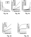
- Logarithmizing the pulse response is based on the assumption that the pulse response decays exponentially when approximated.
- a logarithm of the pulse response as in the figure Figure 5a shown, provides approximately linearly falling curves, especially for non-ferrous metals such as aluminum
- the target object distance can be determined from the axis intercept. However, both courses differ significantly from each other, so that determining the distance would depend on the material.
- the average slope for Alu and St37 shown in the figure Figure 5c differs significantly from each other for all target object distances shown. This parameter can be used to determine to what extent the target object is made of aluminum or St37, regardless of the distance.
- the target object distance can be determined independently of the material from the axis intercept by comparing it with the calibration values stored in the controller.
- logarithm represents a relatively complex calculation operation for a microcontroller, which typically takes several microseconds, even for a modern controller with high clock speeds.
Landscapes
- Physics & Mathematics (AREA)
- Engineering & Computer Science (AREA)
- Remote Sensing (AREA)
- Life Sciences & Earth Sciences (AREA)
- Electromagnetism (AREA)
- Environmental & Geological Engineering (AREA)
- Geology (AREA)
- General Life Sciences & Earth Sciences (AREA)
- General Physics & Mathematics (AREA)
- Geophysics (AREA)
- Measurement Of Length, Angles, Or The Like Using Electric Or Magnetic Means (AREA)
- Geophysics And Detection Of Objects (AREA)
Claims (13)
- Unité de capteur de proximité inductive (10) pour détecter un corps de détection, lequel corps de détection présente des propriétés métalliques, comprenant- une bobine de capteur (12) soumise à des signaux pulsés espacés entre eux dans le temps,- une unité d'évaluation (14), laquelle unité d'évaluation (14) est conçue pour mesurer des valeurs de tension ou d'intensité du signal pulsé à plusieurs instants d'échantillonnage et pour définir un signal chronologique réel à partir des valeurs mesurées (x1, x2, x3) et- une unité de mémoire (16), dans laquelle unité de mémoire (16) au moins trois valeurs (x1, x2, x3) d'un signal chronologique de référence sont mémorisées pour le corps de détection,
l'unité d'évaluation (14) étant conçue- pour définir, à partir d'au moins trois paires des valeurs définies à partir de trois valeurs (x1, x2, x3) du signal chronologique réel et de trois valeurs correspondantes (y1, y2, y3) du signal chronologique de référence, une courbe d'évaluation établissant un lien fonctionnel entre le signal chronologique réel et le signal chronologique de référence, et- pour déterminer une valeur de linéarité de la courbe d'évaluation afin de vérifier le lien fonctionnel, et- pour déterminer à l'aide de la valeur de linéarité le type de métal faisant office de propriété d'objet du corps de détection. - Unité de capteur de proximité inductive (10) selon la revendication 1, caractérisée en ce que l'unité d'évaluation (14) est conçue pour déterminer, en plus du type de métal, au moins une autre propriété d'objet du corps de détection, dans la mesure où le lien fonctionnel est linéaire au moins sur une plage de valeurs.
- Unité de capteur de proximité inductive (10) selon la revendication 1 ou la revendication 2, caractérisée en ce que l'unité d'évaluation (14) est conçue pour déterminer en tant qu'autre autre propriété d'objet une distance par rapport au corps de détection et/ou une orientation spatiale et/ou une épaisseur d'une couche métallique du corps de détection.
- Unité de capteur de proximité inductive (10) selon la revendication 1 ou la revendication 2, caractérisée en ce que l'unité d'évaluation (14) est conçue pour déterminer la distance par rapport au corps de détection à partir de l'inclinaison de la pente de la courbe d'évaluation.
- Procédé pour la détermination d'une propriété d'objet d'un corps de détection métallique avec une unité de capteur de proximité inductive (10) selon lequel- l'unité de capteur de proximité inductive (10) comprend une bobine de capteur (12), un circuit de commande, un circuit de réception, une unité de mémoire (16) et une unité d'évaluation (14),- la bobine de capteur (12) est soumise à des signaux pulsés espacés entre eux dans le temps, un signal d'excitation étant appliqué à la bobine de capteur (12) par le biais du circuit de commande et des valeurs de tension ou d'intensité étant mesurées à plusieurs instants d'échantillonnage,- un signal chronologique réel est déterminé par l'unité d'évaluation à partir des valeurs mesurées,- au moins trois valeurs (x1, x2, x3) d'un signal chronologique de référence sont déposées dans l'unité de mémoire (16) pour le corps d'enregistrement, et
au moyen de l'unité d'évaluation (14),- au moins trois paires des valeurs sont définies à partir de trois valeurs (x1, x2, x3) du signal chronologique réel et de trois valeurs correspondantes (y1, y2, y3) du signal chronologique de référence,- une courbe d'évaluation établissant un lien fonctionnel entre le signal chronologique réel et le signal chronologique de référence est établie au moyen des paires de valeurs (xi, yi),- une valeur de linéarité est déterminée pour vérifier le lien fonctionnel, et- le type de métal faisant office de propriété d'objet du corps de détection est déterminé à l'aide de la valeur de linéarité. - Procédé pour la détermination d'une propriété d'objet d'un corps de détection métallique selon la revendication 5, caractérisé en ce qu'au moins une autre propriété d'objet du corps de détection est déterminée au moyen de l'unité d'évaluation (14), dans la mesure où le lien fonctionnel est linéaire au moins sur une plage de valeurs.
- Procédé pour la détermination d'une propriété d'objet d'un corps de détection métallique selon la revendication 5 ou la revendication 6, caractérisé en ce qu'une distance par rapport au corps de détection et/ou une orientation spatiale et/ou une épaisseur d'une couche métallique du corps de détection est déterminée en tant qu'autre propriété d'objet au moyen de l'unité d'évaluation (14).
- Procédé pour la détermination d'une propriété d'objet d'un corps de détection métallique selon une des revendications 5 à 7, caractérisé en ce que des valeurs (x1, x2, x3) de signaux chronologiques de référence sont déposées dans l'unité de mémoire (16) pour différents types de corps d'enregistrement.
- Procédé pour la détermination d'une propriété d'objet d'un corps de détection métallique selon une des revendications 5 à 8, caractérisé en ce que la distance par rapport au corps de détection est déterminée à l'aide de l'inclinaison de la pente de la courbe d'évaluation.
- Procédé pour la détermination d'une propriété d'objet d'un corps de détection métallique selon une des revendications 5 à 9, caractérisé en ce qu'une somme des carrés des écarts entre la droite de régression et le signal chronologique de référence est établie comme mesure de la coïncidence entre le signal chronologique réel et le signal chronologique de référence.
- Procédé pour la détermination d'une propriété d'objet d'un corps de détection métallique selon une des revendications 5 à 10, caractérisé en ce qu'un coefficient de corrélation de Bravais-Pearson est établi comme mesure de la linéarité de la courbe d'évaluation entre le signal chronologique réel et le signal chronologique de référence.
- Procédé pour la détermination d'une propriété d'objet d'un corps de détection métallique selon une des revendications 5 à 11, caractérisé en ce que la distance par rapport au corps de détection est déterminée indépendamment des propriétés métalliques au moyen de l'unité d'évaluation.
- Procédé pour la détermination d'une propriété d'objet d'un corps de détection métallique selon une des revendications 5 à 12, caractérisé en ce qu'un signal d'évaluation est émis par l'unité d'évaluation uniquement quand la linéarité du signal d'évaluation dépasse un seuil prédéfini.
Applications Claiming Priority (1)
| Application Number | Priority Date | Filing Date | Title |
|---|---|---|---|
| DE102021000156.7A DE102021000156A1 (de) | 2021-01-15 | 2021-01-15 | lnduktive Annäherungssensoreinheit und Verfahren zur Bestimmung einer Objekteigenschaft eines metallischen Erfassungskörpers |
Publications (2)
| Publication Number | Publication Date |
|---|---|
| EP4030199A1 EP4030199A1 (fr) | 2022-07-20 |
| EP4030199B1 true EP4030199B1 (fr) | 2024-03-06 |
Family
ID=79283077
Family Applications (1)
| Application Number | Title | Priority Date | Filing Date |
|---|---|---|---|
| EP22000001.2A Active EP4030199B1 (fr) | 2021-01-15 | 2022-01-04 | Unité inductive de détection de proximité et procédé de détermination d'une propriété d'objet d'un corps métallique de détection |
Country Status (2)
| Country | Link |
|---|---|
| EP (1) | EP4030199B1 (fr) |
| DE (1) | DE102021000156A1 (fr) |
Families Citing this family (2)
| Publication number | Priority date | Publication date | Assignee | Title |
|---|---|---|---|---|
| CN117571814B (zh) * | 2023-11-30 | 2024-04-02 | 科瑞工业自动化系统(苏州)有限公司 | 一种非接触式金属材质检测方法 |
| EP4571271A1 (fr) | 2023-12-11 | 2025-06-18 | Pepperl+Fuchs SE | Système de mesure destiné à fonctionner avec différents types de têtes de capteurs |
Family Cites Families (7)
| Publication number | Priority date | Publication date | Assignee | Title |
|---|---|---|---|---|
| ATE82451T1 (de) | 1990-12-21 | 1992-11-15 | Detra Sa | Induktiver naeherungssensor. |
| DE19506339C2 (de) | 1995-02-23 | 1998-01-15 | Klaus Ebinger | Verfahren und Schaltungsvorrichtung zur elektromagnetischen Detektion von Objekten |
| DE19530987C1 (de) | 1995-08-23 | 1997-02-13 | Elmed Dr Ing Mense Gmbh | Verfahren zum Auswerten der Signale eines Metalldetektors |
| DE102009058549A1 (de) | 2009-12-17 | 2011-06-22 | ThyssenKrupp Fördertechnik GmbH, 45143 | Detektionseinrichtung für eine Bandfördereinrichtung und Verfahren zur Detektion von elektrischen leitfähigen Fremdkörpern im Fördergut einer Bandfördereinrichtung |
| CN105122009B (zh) | 2013-03-19 | 2017-09-15 | 巴鲁夫公司 | 电感式位移测量传感器和用于操作所述传感器的方法 |
| DE102013209805A1 (de) | 2013-05-27 | 2014-11-27 | iCONTROLS k.s. | Induktiver Sensor |
| JP6880861B2 (ja) | 2017-03-15 | 2021-06-02 | オムロン株式会社 | 近接センサおよび検知方法 |
-
2021
- 2021-01-15 DE DE102021000156.7A patent/DE102021000156A1/de not_active Withdrawn
-
2022
- 2022-01-04 EP EP22000001.2A patent/EP4030199B1/fr active Active
Also Published As
| Publication number | Publication date |
|---|---|
| DE102021000156A1 (de) | 2022-07-21 |
| EP4030199A1 (fr) | 2022-07-20 |
Similar Documents
| Publication | Publication Date | Title |
|---|---|---|
| EP1969320B1 (fr) | Circuit d'évaluation et de compensation d'un capteur inductif de déplacement | |
| DE3813739C2 (fr) | ||
| EP4030199B1 (fr) | Unité inductive de détection de proximité et procédé de détermination d'une propriété d'objet d'un corps métallique de détection | |
| WO2012140265A2 (fr) | Dispositif et procédé de détection d'objets électriquement conducteurs | |
| EP2312338A1 (fr) | Dispositif et procédé de détection d'objets conducteurs d'électricité | |
| EP2994725A1 (fr) | Procédé permettant de surveiller au moins une propriété spécifique à un fluide pour une mesure de niveau | |
| EP1847810B1 (fr) | Procédé et dispositif destinés à la détection de position | |
| DE3228447C2 (de) | Meßverfahren zur Erkennung von metallischen Gegenständen und Metalldetektor zur Durchführung des Verfahrens | |
| DE102015107221B4 (de) | Elektromagnetischer Näherungssensor und Verfahren zur Erfassung eines Zielobjekts | |
| EP0654685A2 (fr) | Dispositif et procédé pour la détection des objets métalliques | |
| DE19506339C2 (de) | Verfahren und Schaltungsvorrichtung zur elektromagnetischen Detektion von Objekten | |
| EP3824323B1 (fr) | Détecteur servant à détecter du matériau électriquement conducteur | |
| EP4030622A1 (fr) | Unité inductive de détection de proximité et procédé de détection des dysfonctionnements de l'unité inductive de détection de proximité | |
| EP3829064B1 (fr) | Capteurs destinés à déterminer une valeur de sortie, procédé d'évaluation d'un signal de capteur et procédé d'apprentissage d'une unité de sortie destinée à évaluer un signal de capteur | |
| WO2014191352A2 (fr) | Capteur inductif | |
| DE2641798C3 (de) | Verfahren und Einrichtung zum berührungslosen Ermitteln physikalischer oder geometrischer Eigenschaften | |
| EP2981851B1 (fr) | Appareil de recherche d'objets et procédé de localisation d'un objet métallique et/ou aimantable | |
| DE102024104827B3 (de) | Verfahren zum Betreiben eines induktiven Näherungssensors sowie Vorrichtung zum Betreiben eines solchen Verfahrens und Luftfahrzeug mit einer solchen Vorrichtung | |
| DE69618623T2 (de) | Induktive vorrichtung zur bestimmung der lage und der abmessungen von messobjekten aus elektrisch leitfähigem material | |
| EP1093224A2 (fr) | Détecteur d'impulsions et procédé pour la détection d'impulsions sinusoidales | |
| DE102017003657A1 (de) | Verfahren zum Auswerten eines Sensorsystems und Vorrichtung zur Ausführung eines entsprechenden Verfahrens | |
| DE19730952A1 (de) | Verfahren und Vorrichtung zur elektromagnetischen Detektion von Objekten | |
| DE102020202361A1 (de) | Verfahren und Vorrichtung zur Auswertung einer qPCR-Kurve | |
| DE2705624A1 (de) | Messgeraet | |
| DE102018005248A1 (de) | Kapazitives Sensorsystem zur Berührungserkennung |
Legal Events
| Date | Code | Title | Description |
|---|---|---|---|
| PUAI | Public reference made under article 153(3) epc to a published international application that has entered the european phase |
Free format text: ORIGINAL CODE: 0009012 |
|
| STAA | Information on the status of an ep patent application or granted ep patent |
Free format text: STATUS: THE APPLICATION HAS BEEN PUBLISHED |
|
| AK | Designated contracting states |
Kind code of ref document: A1 Designated state(s): AL AT BE BG CH CY CZ DE DK EE ES FI FR GB GR HR HU IE IS IT LI LT LU LV MC MK MT NL NO PL PT RO RS SE SI SK SM TR |
|
| STAA | Information on the status of an ep patent application or granted ep patent |
Free format text: STATUS: REQUEST FOR EXAMINATION WAS MADE |
|
| 17P | Request for examination filed |
Effective date: 20221103 |
|
| RBV | Designated contracting states (corrected) |
Designated state(s): AL AT BE BG CH CY CZ DE DK EE ES FI FR GB GR HR HU IE IS IT LI LT LU LV MC MK MT NL NO PL PT RO RS SE SI SK SM TR |
|
| GRAP | Despatch of communication of intention to grant a patent |
Free format text: ORIGINAL CODE: EPIDOSNIGR1 |
|
| STAA | Information on the status of an ep patent application or granted ep patent |
Free format text: STATUS: GRANT OF PATENT IS INTENDED |
|
| INTG | Intention to grant announced |
Effective date: 20231128 |
|
| GRAS | Grant fee paid |
Free format text: ORIGINAL CODE: EPIDOSNIGR3 |
|
| GRAA | (expected) grant |
Free format text: ORIGINAL CODE: 0009210 |
|
| STAA | Information on the status of an ep patent application or granted ep patent |
Free format text: STATUS: THE PATENT HAS BEEN GRANTED |
|
| AK | Designated contracting states |
Kind code of ref document: B1 Designated state(s): AL AT BE BG CH CY CZ DE DK EE ES FI FR GB GR HR HU IE IS IT LI LT LU LV MC MK MT NL NO PL PT RO RS SE SI SK SM TR |
|
| REG | Reference to a national code |
Ref country code: CH Ref legal event code: EP |
|
| REG | Reference to a national code |
Ref country code: DE Ref legal event code: R096 Ref document number: 502022000573 Country of ref document: DE |
|
| REG | Reference to a national code |
Ref country code: IE Ref legal event code: FG4D Free format text: LANGUAGE OF EP DOCUMENT: GERMAN |
|
| REG | Reference to a national code |
Ref country code: LT Ref legal event code: MG9D |
|
| PG25 | Lapsed in a contracting state [announced via postgrant information from national office to epo] |
Ref country code: LT Free format text: LAPSE BECAUSE OF FAILURE TO SUBMIT A TRANSLATION OF THE DESCRIPTION OR TO PAY THE FEE WITHIN THE PRESCRIBED TIME-LIMIT Effective date: 20240306 |
|
| REG | Reference to a national code |
Ref country code: NL Ref legal event code: MP Effective date: 20240306 |
|
| PG25 | Lapsed in a contracting state [announced via postgrant information from national office to epo] |
Ref country code: GR Free format text: LAPSE BECAUSE OF FAILURE TO SUBMIT A TRANSLATION OF THE DESCRIPTION OR TO PAY THE FEE WITHIN THE PRESCRIBED TIME-LIMIT Effective date: 20240607 |
|
| PG25 | Lapsed in a contracting state [announced via postgrant information from national office to epo] |
Ref country code: HR Free format text: LAPSE BECAUSE OF FAILURE TO SUBMIT A TRANSLATION OF THE DESCRIPTION OR TO PAY THE FEE WITHIN THE PRESCRIBED TIME-LIMIT Effective date: 20240306 Ref country code: RS Free format text: LAPSE BECAUSE OF FAILURE TO SUBMIT A TRANSLATION OF THE DESCRIPTION OR TO PAY THE FEE WITHIN THE PRESCRIBED TIME-LIMIT Effective date: 20240606 |
|
| PG25 | Lapsed in a contracting state [announced via postgrant information from national office to epo] |
Ref country code: ES Free format text: LAPSE BECAUSE OF FAILURE TO SUBMIT A TRANSLATION OF THE DESCRIPTION OR TO PAY THE FEE WITHIN THE PRESCRIBED TIME-LIMIT Effective date: 20240306 |
|
| PG25 | Lapsed in a contracting state [announced via postgrant information from national office to epo] |
Ref country code: RS Free format text: LAPSE BECAUSE OF FAILURE TO SUBMIT A TRANSLATION OF THE DESCRIPTION OR TO PAY THE FEE WITHIN THE PRESCRIBED TIME-LIMIT Effective date: 20240606 Ref country code: NO Free format text: LAPSE BECAUSE OF FAILURE TO SUBMIT A TRANSLATION OF THE DESCRIPTION OR TO PAY THE FEE WITHIN THE PRESCRIBED TIME-LIMIT Effective date: 20240606 Ref country code: LT Free format text: LAPSE BECAUSE OF FAILURE TO SUBMIT A TRANSLATION OF THE DESCRIPTION OR TO PAY THE FEE WITHIN THE PRESCRIBED TIME-LIMIT Effective date: 20240306 Ref country code: HR Free format text: LAPSE BECAUSE OF FAILURE TO SUBMIT A TRANSLATION OF THE DESCRIPTION OR TO PAY THE FEE WITHIN THE PRESCRIBED TIME-LIMIT Effective date: 20240306 Ref country code: GR Free format text: LAPSE BECAUSE OF FAILURE TO SUBMIT A TRANSLATION OF THE DESCRIPTION OR TO PAY THE FEE WITHIN THE PRESCRIBED TIME-LIMIT Effective date: 20240607 Ref country code: FI Free format text: LAPSE BECAUSE OF FAILURE TO SUBMIT A TRANSLATION OF THE DESCRIPTION OR TO PAY THE FEE WITHIN THE PRESCRIBED TIME-LIMIT Effective date: 20240306 Ref country code: ES Free format text: LAPSE BECAUSE OF FAILURE TO SUBMIT A TRANSLATION OF THE DESCRIPTION OR TO PAY THE FEE WITHIN THE PRESCRIBED TIME-LIMIT Effective date: 20240306 Ref country code: BG Free format text: LAPSE BECAUSE OF FAILURE TO SUBMIT A TRANSLATION OF THE DESCRIPTION OR TO PAY THE FEE WITHIN THE PRESCRIBED TIME-LIMIT Effective date: 20240306 |
|
| PG25 | Lapsed in a contracting state [announced via postgrant information from national office to epo] |
Ref country code: SE Free format text: LAPSE BECAUSE OF FAILURE TO SUBMIT A TRANSLATION OF THE DESCRIPTION OR TO PAY THE FEE WITHIN THE PRESCRIBED TIME-LIMIT Effective date: 20240306 Ref country code: LV Free format text: LAPSE BECAUSE OF FAILURE TO SUBMIT A TRANSLATION OF THE DESCRIPTION OR TO PAY THE FEE WITHIN THE PRESCRIBED TIME-LIMIT Effective date: 20240306 |
|
| PG25 | Lapsed in a contracting state [announced via postgrant information from national office to epo] |
Ref country code: NL Free format text: LAPSE BECAUSE OF FAILURE TO SUBMIT A TRANSLATION OF THE DESCRIPTION OR TO PAY THE FEE WITHIN THE PRESCRIBED TIME-LIMIT Effective date: 20240306 |
|
| PG25 | Lapsed in a contracting state [announced via postgrant information from national office to epo] |
Ref country code: NL Free format text: LAPSE BECAUSE OF FAILURE TO SUBMIT A TRANSLATION OF THE DESCRIPTION OR TO PAY THE FEE WITHIN THE PRESCRIBED TIME-LIMIT Effective date: 20240306 |
|
| PG25 | Lapsed in a contracting state [announced via postgrant information from national office to epo] |
Ref country code: IS Free format text: LAPSE BECAUSE OF FAILURE TO SUBMIT A TRANSLATION OF THE DESCRIPTION OR TO PAY THE FEE WITHIN THE PRESCRIBED TIME-LIMIT Effective date: 20240706 |
|
| PG25 | Lapsed in a contracting state [announced via postgrant information from national office to epo] |
Ref country code: PT Free format text: LAPSE BECAUSE OF FAILURE TO SUBMIT A TRANSLATION OF THE DESCRIPTION OR TO PAY THE FEE WITHIN THE PRESCRIBED TIME-LIMIT Effective date: 20240708 Ref country code: SM Free format text: LAPSE BECAUSE OF FAILURE TO SUBMIT A TRANSLATION OF THE DESCRIPTION OR TO PAY THE FEE WITHIN THE PRESCRIBED TIME-LIMIT Effective date: 20240306 |
|
| PG25 | Lapsed in a contracting state [announced via postgrant information from national office to epo] |
Ref country code: EE Free format text: LAPSE BECAUSE OF FAILURE TO SUBMIT A TRANSLATION OF THE DESCRIPTION OR TO PAY THE FEE WITHIN THE PRESCRIBED TIME-LIMIT Effective date: 20240306 |
|
| PG25 | Lapsed in a contracting state [announced via postgrant information from national office to epo] |
Ref country code: PL Free format text: LAPSE BECAUSE OF FAILURE TO SUBMIT A TRANSLATION OF THE DESCRIPTION OR TO PAY THE FEE WITHIN THE PRESCRIBED TIME-LIMIT Effective date: 20240306 |
|
| PG25 | Lapsed in a contracting state [announced via postgrant information from national office to epo] |
Ref country code: SK Free format text: LAPSE BECAUSE OF FAILURE TO SUBMIT A TRANSLATION OF THE DESCRIPTION OR TO PAY THE FEE WITHIN THE PRESCRIBED TIME-LIMIT Effective date: 20240306 |
|
| PG25 | Lapsed in a contracting state [announced via postgrant information from national office to epo] |
Ref country code: SM Free format text: LAPSE BECAUSE OF FAILURE TO SUBMIT A TRANSLATION OF THE DESCRIPTION OR TO PAY THE FEE WITHIN THE PRESCRIBED TIME-LIMIT Effective date: 20240306 Ref country code: SK Free format text: LAPSE BECAUSE OF FAILURE TO SUBMIT A TRANSLATION OF THE DESCRIPTION OR TO PAY THE FEE WITHIN THE PRESCRIBED TIME-LIMIT Effective date: 20240306 Ref country code: RO Free format text: LAPSE BECAUSE OF FAILURE TO SUBMIT A TRANSLATION OF THE DESCRIPTION OR TO PAY THE FEE WITHIN THE PRESCRIBED TIME-LIMIT Effective date: 20240306 Ref country code: PT Free format text: LAPSE BECAUSE OF FAILURE TO SUBMIT A TRANSLATION OF THE DESCRIPTION OR TO PAY THE FEE WITHIN THE PRESCRIBED TIME-LIMIT Effective date: 20240708 Ref country code: PL Free format text: LAPSE BECAUSE OF FAILURE TO SUBMIT A TRANSLATION OF THE DESCRIPTION OR TO PAY THE FEE WITHIN THE PRESCRIBED TIME-LIMIT Effective date: 20240306 Ref country code: IS Free format text: LAPSE BECAUSE OF FAILURE TO SUBMIT A TRANSLATION OF THE DESCRIPTION OR TO PAY THE FEE WITHIN THE PRESCRIBED TIME-LIMIT Effective date: 20240706 Ref country code: EE Free format text: LAPSE BECAUSE OF FAILURE TO SUBMIT A TRANSLATION OF THE DESCRIPTION OR TO PAY THE FEE WITHIN THE PRESCRIBED TIME-LIMIT Effective date: 20240306 |
|
| PG25 | Lapsed in a contracting state [announced via postgrant information from national office to epo] |
Ref country code: IT Free format text: LAPSE BECAUSE OF FAILURE TO SUBMIT A TRANSLATION OF THE DESCRIPTION OR TO PAY THE FEE WITHIN THE PRESCRIBED TIME-LIMIT Effective date: 20240306 |
|
| REG | Reference to a national code |
Ref country code: DE Ref legal event code: R097 Ref document number: 502022000573 Country of ref document: DE |
|
| PG25 | Lapsed in a contracting state [announced via postgrant information from national office to epo] |
Ref country code: IT Free format text: LAPSE BECAUSE OF FAILURE TO SUBMIT A TRANSLATION OF THE DESCRIPTION OR TO PAY THE FEE WITHIN THE PRESCRIBED TIME-LIMIT Effective date: 20240306 |
|
| PLBE | No opposition filed within time limit |
Free format text: ORIGINAL CODE: 0009261 |
|
| STAA | Information on the status of an ep patent application or granted ep patent |
Free format text: STATUS: NO OPPOSITION FILED WITHIN TIME LIMIT |
|
| PG25 | Lapsed in a contracting state [announced via postgrant information from national office to epo] |
Ref country code: DK Free format text: LAPSE BECAUSE OF FAILURE TO SUBMIT A TRANSLATION OF THE DESCRIPTION OR TO PAY THE FEE WITHIN THE PRESCRIBED TIME-LIMIT Effective date: 20240306 |
|
| PG25 | Lapsed in a contracting state [announced via postgrant information from national office to epo] |
Ref country code: DK Free format text: LAPSE BECAUSE OF FAILURE TO SUBMIT A TRANSLATION OF THE DESCRIPTION OR TO PAY THE FEE WITHIN THE PRESCRIBED TIME-LIMIT Effective date: 20240306 |
|
| 26N | No opposition filed |
Effective date: 20241209 |
|
| PG25 | Lapsed in a contracting state [announced via postgrant information from national office to epo] |
Ref country code: SI Free format text: LAPSE BECAUSE OF FAILURE TO SUBMIT A TRANSLATION OF THE DESCRIPTION OR TO PAY THE FEE WITHIN THE PRESCRIBED TIME-LIMIT Effective date: 20240306 |
|
| PGFP | Annual fee paid to national office [announced via postgrant information from national office to epo] |
Ref country code: CH Payment date: 20250201 Year of fee payment: 4 |
|
| PG25 | Lapsed in a contracting state [announced via postgrant information from national office to epo] |
Ref country code: LU Free format text: LAPSE BECAUSE OF NON-PAYMENT OF DUE FEES Effective date: 20250104 Ref country code: MC Free format text: LAPSE BECAUSE OF FAILURE TO SUBMIT A TRANSLATION OF THE DESCRIPTION OR TO PAY THE FEE WITHIN THE PRESCRIBED TIME-LIMIT Effective date: 20240306 |
|
| PG25 | Lapsed in a contracting state [announced via postgrant information from national office to epo] |
Ref country code: BE Free format text: LAPSE BECAUSE OF NON-PAYMENT OF DUE FEES Effective date: 20250131 |
|
| REG | Reference to a national code |
Ref country code: BE Ref legal event code: MM Effective date: 20250131 |
|
| PG25 | Lapsed in a contracting state [announced via postgrant information from national office to epo] |
Ref country code: IE Free format text: LAPSE BECAUSE OF NON-PAYMENT OF DUE FEES Effective date: 20250104 |
|
| PGFP | Annual fee paid to national office [announced via postgrant information from national office to epo] |
Ref country code: CZ Payment date: 20251219 Year of fee payment: 5 |
|
| REG | Reference to a national code |
Ref country code: CH Ref legal event code: U11 Free format text: ST27 STATUS EVENT CODE: U-0-0-U10-U11 (AS PROVIDED BY THE NATIONAL OFFICE) Effective date: 20260201 |
|
| PGFP | Annual fee paid to national office [announced via postgrant information from national office to epo] |
Ref country code: DE Payment date: 20260120 Year of fee payment: 5 |
|
| PGFP | Annual fee paid to national office [announced via postgrant information from national office to epo] |
Ref country code: AT Payment date: 20260301 Year of fee payment: 5 |
|
| PGFP | Annual fee paid to national office [announced via postgrant information from national office to epo] |
Ref country code: FR Payment date: 20260128 Year of fee payment: 5 |