EP4030552A1 - Batteriepack und vorrichtung damit - Google Patents
Batteriepack und vorrichtung damit Download PDFInfo
- Publication number
- EP4030552A1 EP4030552A1 EP20894260.7A EP20894260A EP4030552A1 EP 4030552 A1 EP4030552 A1 EP 4030552A1 EP 20894260 A EP20894260 A EP 20894260A EP 4030552 A1 EP4030552 A1 EP 4030552A1
- Authority
- EP
- European Patent Office
- Prior art keywords
- fuse
- battery pack
- battery
- battery module
- fixing member
- Prior art date
- Legal status (The legal status is an assumption and is not a legal conclusion. Google has not performed a legal analysis and makes no representation as to the accuracy of the status listed.)
- Pending
Links
Images


Classifications
-
- H—ELECTRICITY
- H01—ELECTRIC ELEMENTS
- H01M—PROCESSES OR MEANS, e.g. BATTERIES, FOR THE DIRECT CONVERSION OF CHEMICAL ENERGY INTO ELECTRICAL ENERGY
- H01M50/00—Constructional details or processes of manufacture of the non-active parts of electrochemical cells other than fuel cells, e.g. hybrid cells
- H01M50/20—Mountings; Secondary casings or frames; Racks, modules or packs; Suspension devices; Shock absorbers; Transport or carrying devices; Holders
- H01M50/204—Racks, modules or packs for multiple batteries or multiple cells
- H01M50/207—Racks, modules or packs for multiple batteries or multiple cells characterised by their shape
- H01M50/209—Racks, modules or packs for multiple batteries or multiple cells characterised by their shape adapted for prismatic or rectangular cells
-
- H—ELECTRICITY
- H01—ELECTRIC ELEMENTS
- H01M—PROCESSES OR MEANS, e.g. BATTERIES, FOR THE DIRECT CONVERSION OF CHEMICAL ENERGY INTO ELECTRICAL ENERGY
- H01M50/00—Constructional details or processes of manufacture of the non-active parts of electrochemical cells other than fuel cells, e.g. hybrid cells
- H01M50/50—Current conducting connections for cells or batteries
- H01M50/502—Interconnectors for connecting terminals of adjacent batteries; Interconnectors for connecting cells outside a battery casing
-
- B—PERFORMING OPERATIONS; TRANSPORTING
- B60—VEHICLES IN GENERAL
- B60L—PROPULSION OF ELECTRICALLY-PROPELLED VEHICLES; SUPPLYING ELECTRIC POWER FOR AUXILIARY EQUIPMENT OF ELECTRICALLY-PROPELLED VEHICLES; ELECTRODYNAMIC BRAKE SYSTEMS FOR VEHICLES IN GENERAL; MAGNETIC SUSPENSION OR LEVITATION FOR VEHICLES; MONITORING OPERATING VARIABLES OF ELECTRICALLY-PROPELLED VEHICLES; ELECTRIC SAFETY DEVICES FOR ELECTRICALLY-PROPELLED VEHICLES
- B60L50/00—Electric propulsion with power supplied within the vehicle
- B60L50/50—Electric propulsion with power supplied within the vehicle using propulsion power supplied by batteries or fuel cells
- B60L50/60—Electric propulsion with power supplied within the vehicle using propulsion power supplied by batteries or fuel cells using power supplied by batteries
- B60L50/66—Arrangements of batteries
-
- H—ELECTRICITY
- H01—ELECTRIC ELEMENTS
- H01M—PROCESSES OR MEANS, e.g. BATTERIES, FOR THE DIRECT CONVERSION OF CHEMICAL ENERGY INTO ELECTRICAL ENERGY
- H01M10/00—Secondary cells; Manufacture thereof
- H01M10/42—Methods or arrangements for servicing or maintenance of secondary cells or secondary half-cells
- H01M10/425—Structural combination with electronic components, e.g. electronic circuits integrated to the outside of the casing
-
- H—ELECTRICITY
- H01—ELECTRIC ELEMENTS
- H01M—PROCESSES OR MEANS, e.g. BATTERIES, FOR THE DIRECT CONVERSION OF CHEMICAL ENERGY INTO ELECTRICAL ENERGY
- H01M50/00—Constructional details or processes of manufacture of the non-active parts of electrochemical cells other than fuel cells, e.g. hybrid cells
- H01M50/20—Mountings; Secondary casings or frames; Racks, modules or packs; Suspension devices; Shock absorbers; Transport or carrying devices; Holders
-
- H—ELECTRICITY
- H01—ELECTRIC ELEMENTS
- H01M—PROCESSES OR MEANS, e.g. BATTERIES, FOR THE DIRECT CONVERSION OF CHEMICAL ENERGY INTO ELECTRICAL ENERGY
- H01M50/00—Constructional details or processes of manufacture of the non-active parts of electrochemical cells other than fuel cells, e.g. hybrid cells
- H01M50/20—Mountings; Secondary casings or frames; Racks, modules or packs; Suspension devices; Shock absorbers; Transport or carrying devices; Holders
- H01M50/204—Racks, modules or packs for multiple batteries or multiple cells
-
- H—ELECTRICITY
- H01—ELECTRIC ELEMENTS
- H01M—PROCESSES OR MEANS, e.g. BATTERIES, FOR THE DIRECT CONVERSION OF CHEMICAL ENERGY INTO ELECTRICAL ENERGY
- H01M50/00—Constructional details or processes of manufacture of the non-active parts of electrochemical cells other than fuel cells, e.g. hybrid cells
- H01M50/20—Mountings; Secondary casings or frames; Racks, modules or packs; Suspension devices; Shock absorbers; Transport or carrying devices; Holders
- H01M50/204—Racks, modules or packs for multiple batteries or multiple cells
- H01M50/207—Racks, modules or packs for multiple batteries or multiple cells characterised by their shape
- H01M50/211—Racks, modules or packs for multiple batteries or multiple cells characterised by their shape adapted for pouch cells
-
- H—ELECTRICITY
- H01—ELECTRIC ELEMENTS
- H01M—PROCESSES OR MEANS, e.g. BATTERIES, FOR THE DIRECT CONVERSION OF CHEMICAL ENERGY INTO ELECTRICAL ENERGY
- H01M50/00—Constructional details or processes of manufacture of the non-active parts of electrochemical cells other than fuel cells, e.g. hybrid cells
- H01M50/20—Mountings; Secondary casings or frames; Racks, modules or packs; Suspension devices; Shock absorbers; Transport or carrying devices; Holders
- H01M50/233—Mountings; Secondary casings or frames; Racks, modules or packs; Suspension devices; Shock absorbers; Transport or carrying devices; Holders characterised by physical properties of casings or racks, e.g. dimensions
- H01M50/24—Mountings; Secondary casings or frames; Racks, modules or packs; Suspension devices; Shock absorbers; Transport or carrying devices; Holders characterised by physical properties of casings or racks, e.g. dimensions adapted for protecting batteries from their environment, e.g. from corrosion
-
- H—ELECTRICITY
- H01—ELECTRIC ELEMENTS
- H01M—PROCESSES OR MEANS, e.g. BATTERIES, FOR THE DIRECT CONVERSION OF CHEMICAL ENERGY INTO ELECTRICAL ENERGY
- H01M50/00—Constructional details or processes of manufacture of the non-active parts of electrochemical cells other than fuel cells, e.g. hybrid cells
- H01M50/20—Mountings; Secondary casings or frames; Racks, modules or packs; Suspension devices; Shock absorbers; Transport or carrying devices; Holders
- H01M50/258—Modular batteries; Casings provided with means for assembling
-
- H—ELECTRICITY
- H01—ELECTRIC ELEMENTS
- H01M—PROCESSES OR MEANS, e.g. BATTERIES, FOR THE DIRECT CONVERSION OF CHEMICAL ENERGY INTO ELECTRICAL ENERGY
- H01M50/00—Constructional details or processes of manufacture of the non-active parts of electrochemical cells other than fuel cells, e.g. hybrid cells
- H01M50/50—Current conducting connections for cells or batteries
-
- H—ELECTRICITY
- H01—ELECTRIC ELEMENTS
- H01M—PROCESSES OR MEANS, e.g. BATTERIES, FOR THE DIRECT CONVERSION OF CHEMICAL ENERGY INTO ELECTRICAL ENERGY
- H01M50/00—Constructional details or processes of manufacture of the non-active parts of electrochemical cells other than fuel cells, e.g. hybrid cells
- H01M50/50—Current conducting connections for cells or batteries
- H01M50/502—Interconnectors for connecting terminals of adjacent batteries; Interconnectors for connecting cells outside a battery casing
- H01M50/507—Interconnectors for connecting terminals of adjacent batteries; Interconnectors for connecting cells outside a battery casing comprising an arrangement of two or more busbars within a container structure, e.g. busbar modules
-
- H—ELECTRICITY
- H01—ELECTRIC ELEMENTS
- H01M—PROCESSES OR MEANS, e.g. BATTERIES, FOR THE DIRECT CONVERSION OF CHEMICAL ENERGY INTO ELECTRICAL ENERGY
- H01M50/00—Constructional details or processes of manufacture of the non-active parts of electrochemical cells other than fuel cells, e.g. hybrid cells
- H01M50/50—Current conducting connections for cells or batteries
- H01M50/572—Means for preventing undesired use or discharge
-
- H—ELECTRICITY
- H01—ELECTRIC ELEMENTS
- H01M—PROCESSES OR MEANS, e.g. BATTERIES, FOR THE DIRECT CONVERSION OF CHEMICAL ENERGY INTO ELECTRICAL ENERGY
- H01M50/00—Constructional details or processes of manufacture of the non-active parts of electrochemical cells other than fuel cells, e.g. hybrid cells
- H01M50/50—Current conducting connections for cells or batteries
- H01M50/572—Means for preventing undesired use or discharge
- H01M50/574—Devices or arrangements for the interruption of current
- H01M50/581—Devices or arrangements for the interruption of current in response to temperature
-
- H—ELECTRICITY
- H01—ELECTRIC ELEMENTS
- H01M—PROCESSES OR MEANS, e.g. BATTERIES, FOR THE DIRECT CONVERSION OF CHEMICAL ENERGY INTO ELECTRICAL ENERGY
- H01M50/00—Constructional details or processes of manufacture of the non-active parts of electrochemical cells other than fuel cells, e.g. hybrid cells
- H01M50/50—Current conducting connections for cells or batteries
- H01M50/572—Means for preventing undesired use or discharge
- H01M50/574—Devices or arrangements for the interruption of current
- H01M50/583—Devices or arrangements for the interruption of current in response to current, e.g. fuses
-
- H—ELECTRICITY
- H01—ELECTRIC ELEMENTS
- H01M—PROCESSES OR MEANS, e.g. BATTERIES, FOR THE DIRECT CONVERSION OF CHEMICAL ENERGY INTO ELECTRICAL ENERGY
- H01M2200/00—Safety devices for primary or secondary batteries
- H01M2200/10—Temperature sensitive devices
- H01M2200/103—Fuse
-
- H—ELECTRICITY
- H01—ELECTRIC ELEMENTS
- H01M—PROCESSES OR MEANS, e.g. BATTERIES, FOR THE DIRECT CONVERSION OF CHEMICAL ENERGY INTO ELECTRICAL ENERGY
- H01M2220/00—Batteries for particular applications
- H01M2220/20—Batteries in motive systems, e.g. vehicle, ship, plane
-
- Y—GENERAL TAGGING OF NEW TECHNOLOGICAL DEVELOPMENTS; GENERAL TAGGING OF CROSS-SECTIONAL TECHNOLOGIES SPANNING OVER SEVERAL SECTIONS OF THE IPC; TECHNICAL SUBJECTS COVERED BY FORMER USPC CROSS-REFERENCE ART COLLECTIONS [XRACs] AND DIGESTS
- Y02—TECHNOLOGIES OR APPLICATIONS FOR MITIGATION OR ADAPTATION AGAINST CLIMATE CHANGE
- Y02E—REDUCTION OF GREENHOUSE GAS [GHG] EMISSIONS, RELATED TO ENERGY GENERATION, TRANSMISSION OR DISTRIBUTION
- Y02E60/00—Enabling technologies; Technologies with a potential or indirect contribution to GHG emissions mitigation
- Y02E60/10—Energy storage using batteries
Definitions
- the present disclosure relates to a battery pack and a device including the same, and more particularly to a battery pack including a fuse, and a device including the same.
- Secondary batteries which are easily applied to various product groups and has electrical characteristics such as high energy density, are universally applied not only for a portable device but also for an electric vehicle or a hybrid electric vehicle, an energy storage system or the like, which is driven by an electric driving source.
- Such secondary battery is attracting attention as a new environment-friendly energy source for improving energy efficiency since it gives a primary advantage of remarkably reducing the use of fossil fuels and also does not generate by-products from the use of energy at all.
- the lithium secondary battery has come into the spotlight because they have advantages, for example, hardly exhibiting memory effects compared to nickel-based secondary batteries and thus being freely charged and discharged, and having very low self-discharge rate and high energy density.
- Such lithium secondary battery mainly uses a lithium-based oxide and a carbonaceous material as a positive electrode active material and a negative electrode active material, respectively.
- the lithium secondary battery includes an electrode assembly in which a positive electrode plate and a negative electrode plate respectively coated with the positive electrode active material and the negative electrode active material are disposed with a separator being interposed between them, and an exterior material, i.e., battery case, which seals and accommodates the electrode assembly together with an electrolyte solution.
- the lithium secondary battery may be classified based on the shape of the exterior material into a prismatic-type secondary battery in which the electrode assembly is mounted in a metal can, and a pouch-type secondary battery in which the electrode assembly is mounted in a pouch of an aluminum laminate sheet.
- a battery module in which a large number of battery cells are electrically connected is used.
- a plurality of battery cells is connected to each other in series or parallel to form a cell stack, thereby improving capacity and output.
- a plurality of battery modules can be mounted together with various control and protection systems such as a battery management system (BMS) and a cooling system to form a battery pack.
- BMS battery management system
- the battery pack is formed in a structure in which a large number of battery modules are combined. Thus, when overvoltage, overcurrent or overheating occur in some battery modules, the safety and operating efficiency of the battery pack become a big problem, and thus, a means for detecting and controlling them is required.
- the battery pack includes a fuse that is blown out to interrupt the flow of currents when an overcurrent flows due to a short circuit of a wire or the like.
- a fuse that is blown out to interrupt the flow of currents when an overcurrent flows due to a short circuit of a wire or the like.
- problems may occur in which the fuse box for wrapping the fuse may melt and comes into contact with the internal structure. In this case, the fuse does not cut off the current and an additional event occurs inside the battery pack, and thus, the safety of the battery pack is greatly reduced.
- Embodiments of the present disclosure have been designed to solve the above-mentioned problems of the previously proposed methods, and an object of the present disclosure is to provide a battery pack with improved safety by disposing an additional fixing device for the fuse installed inside the battery pack, and a device including the same.
- a battery pack includes: a first battery module and a second battery module each including a plurality of battery cells; a first bus bar extended from the first battery module and a second bus bar extended from the second battery module; a fuse for connecting the first bus bar and the second bus bar; and a fixing member having heat resistance in which at least a part is located at the lower end part of the fuse.
- the fuse may include a non-conductive part having an electrical insulation, and the fixing member may be located at the lower end part of the non-conductive part.
- the lowermost part of the first battery module may be located higher than the uppermost part of the second battery module.
- the first bus bar may be configured so as to become upward as it goes toward the first battery module, and the second bus bar may be configured so as to become downward as it goes toward the second battery module.
- the first battery module and the second battery module may form a layered structure.
- the fixing member may include at least one of a ceramic material, fiberglass, and plastic material.
- the battery pack may include a fuse box for accommodating the fuse therein, wherein the fuse box may include an outer peripheral frame that wraps the fuse and has one open side, and a cover that covers the one opened side of the outer peripheral frame.
- the outer peripheral frame may include a fixing member frame for wrapping an outer peripheral surface of the fixing member.
- the fixing member frame may be integrated with the outer peripheral frame.
- the fuse box may include an injection material.
- the fixing member may include a clamp part for wrapping at least a part of an outer peripheral surface of the fuse, and the clamp part may support the lower end part of the fuse.
- the clamp part may support the lower end part while wrapping the lower end part, one side part and upper end part of the fuse.
- the fuse may have a cylindrical shape, and the clamp part has a circular clamp shape.
- the fuse can be fixed by the fixing member supporting the lower end part thereof to prevent the fuse from coming into contact with other structures.
- the fixing member can be applied to a fuse product in which only a part has an insulating property, cost reduction can be expected.
- planar when referred to as “planar”, it means when a target portion is viewed from the upper side, and when referred to as “cross-sectional”, it means when a target portion is viewed from the side of a cross section cut vertically.
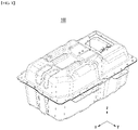
- FIG. 1 is a perspective view of a battery pack 100 according to one embodiment of the present disclosure
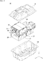
- FIG. 2 is an exploded perspective view of the battery pack 100 of FIG. 1 .
- the battery pack 100 includes a first battery module 110 and a second battery module 120 each including a plurality of battery cells; a first bus bar 210 extended from the first battery module 110 and a second bus bar 220 extended from the second battery module 120; a fuse 300 for connecting the first bus bar 210 and the second bus bar 220; and a fixing member having heat resistance in which at least a part is located at the lower end part of the fuse 300.
- the fixing member will be described in detail later in FIG. 4 .
- the lowermost part of the first battery module 110 may be located higher than the uppermost part of the second battery module 120.
- the first battery module 110 and the second battery module 120 may form a layered structure, the first battery module 110 may be located at the upper layer, and the second battery module may be located at the lower layer.
- the battery pack 100 may further include other battery module in addition to the first battery module 110 and the second battery module 120.
- the battery pack 100 may further include other battery module in addition to the first battery module 110 and the second battery module 120.
- the battery pack 100 may further include other battery module in addition to the first battery module 110 and the second battery module 120.
- two battery modules including the first battery module 110 may be located in the upper layer, and four battery modules including the second battery module 120 may be located in the lower layer.
- the battery module located in the upper layer and the battery module located in the lower layer may be distinguished by a layered structure with a horizontal plate 150 being interposed therebetween.
- the battery pack 100 may include an upper case 130 and a lower case 140 that accommodate battery modules including the first battery module 110 and the second battery module 120 therein.
- the upper case 130 and the lower case 140 may be fastened by bolt-nut connection.
- FIG. 3 is a front view of the battery pack of FIG. 2 as viewed from a direction opposite to the x-axis. More specifically, FIG. 3 is a front view showing a state in which the upper case 130 and the lower case 140 are moved from the battery pack 100 of FIG. 2 .
- a fuse 300 connects a first bus bar 210 extended from the first battery module 110 and a second bus bar 220 extended from the second battery module 120.
- the fuse 300 can cut off the current to interrupt the current between the first battery module 110 and the second battery module 120.
- a side plate 160 may be located on one side of the first battery module 110, and a fuse 300 may be fixed to the side plate 160.
- FIG. 4 is an enlarged perspective view of the fuse 300 of FIG. 3 . More specifically, FIG. 4 shows a state in which the cover 520 of the fuse box 500 is disassembled.
- the battery pack according to the present embodiment includes a fixing member 400 having heat resistance in which at least a part is located at the lower end part of the fuse 300.
- the battery pack according to the present embodiment may include a fuse box 500 that accommodates the fuse 300 therein, wherein the fuse box 500 may include an outer peripheral frame 510 that warps the fuse 300 and has one open side (in the x-axis direction in FIG. 4 ), and a cover 520 that covers the one open side of the outer peripheral frame 510.
- the fuse box 500 including the outer peripheral frame 510 and the cover 520 may include an injection material for designing insulation, and the outer peripheral frame 510 of the fuse box 500 can play a role of fixing the fuse 300 in the inside of the battery pack.
- the outer peripheral frame 510 can be fastened to a side plate 160 so that the fuse 300 can be fixed to the side plate 160.
- the fuse box 500 including the injection material may melt due to high temperature.
- the fuse 300 inside the fuse box 500 is exposed to the outside and the fuse 300 is not properly fixed, so that the fuse 300 can come into contact with other structures which lead to additional events such as ignition or explosion inside the battery pack.
- the battery pack according to the embodiments of the present disclosure has attempted to solve the above problems by including a fixing member 400 having heat resistance in which at least a part is located at the lower end of the fuse 300.
- the fixing member 400 may include at least one of a ceramic material, a fiberglass, and a plastic material.
- the fixing member 400 Even if the fuse box 500 melts due to occurrence of an abnormal condition such as an overcurrent, the fixing member 400 has heat resistance, so that the fuse 300 in which the fixation is released can be prevented from moving downward.
- the fuse 300 can be prevented from coming into contact with internal structures and the like to thereby prevent additional ignition or explosion of the battery pack.
- the fixing member 400 may have a structure that protrudes perpendicularly to the side plate 160. More specifically, the fixing member 400 may be formed by protruding an additional member interposed between the fuse 300 and the side plate 160 as shown in FIG. 4 . Further, unlike that, the fixing member can have a structure which is integrally protruded from the side plate 160.
- the outer peripheral frame 510 may include a fixing member frame 511 that wraps the outer peripheral surface of the fixing member 400, and the fixing member frame 511 may be integrated with the outer peripheral frame 510.
- the fuse box 500 can be stably disposed on the fixing member 400 via the fixing member frame 511. Usually, in a normal operating environment, flow or separation of the fuse box 500 caused by an external shock or the like can be minimized.
- the fuse 300 may be fastened to each of the first bus bar 210 and the second bus bar 220 by a bolt 330 in the fuse box 500.
- the first bus bar 210 may be configured so as to become upward as it goes toward the first battery module 110, and the second bus bar 220 may be configured so as to become downward as it goes toward the second battery module 120. More specifically, the first bus bar 210 may be configured so as to become upward as it goes toward the portion connected with the first battery module 110, and the second bus bar 220 may be configured so as to become downward as it goes toward the portion connected with the second battery module 120.
- the first bus bar 210 and the second bus bar 220 connected with each of them may form a constant angle, such as upward or downward.
- the first bus bar 210 and the second bus bar 220 which forms a constant angle in this way, may further induce a downward movement or irregular flow of the fuse 300 in which the fixation is released.
- the fixing member 400 in the present disclosure is provided with the fuse 300 that is connected with the bus bars 210 and 220 configured to form a certain angle, the effect of improving safety can be further maximized.
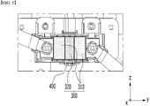
- FIG. 5 is a front view of the fuse of FIG. 4 as viewed from a direction opposite to the x-axis. More specifically, FIG. 5 is a view showing the inside of the fuse 300 as a projection.
- the fuse 300 includes a non-conductive part 320 having an electrical insulation, and the fixing member 400 may be located at a lower end part of the non-conductive part 320.
- the fuse 300 may further include a conductive part 310 having no electrical insulation, and the non-conductive part 320 may be located between the conductive parts 310.
- the positions of the conductive part 310 and the non-conductive part 320 are one exemplary configuration, and embodiments of the present disclosure are not limited thereto.
- the non-conductive part 320 and the conductive part 310 are provided so that the fixing member 400 can also be only applied to a part of the product of the fuse 300 has an insulation property, cost reduction can be expected.
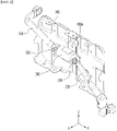
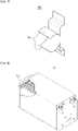
- FIG. 6 is a perspective view showing a fixing member 400a, a fuse 300, a first bus bar 210, a second bus bar 220, and a side plate 160 as a modified embodiment of the present disclosure. For convenience of explanation, illustration of other configurations is omitted.
- FIG. 7 is a perspective view of the fixing member 400a of FIG. 6 .
- the fixing member 400a having heat resistance may include a clamp part 410 that wraps at least a part of the outer peripheral surface of the fuse 300, and the clamp part 410 may support the lower end part of the fuse 300.
- the fixing member 400a may be fixed to the side plate 160 that is located on one side of the first battery module (not shown), and the clamp part 410 may be configured in the shape of supporting the lower end part while wrapping the lower end part, one side part and upper end part of the fuse 300.
- the one side part is a side surface in the direction in which the side plate 160 is located, and the other side part facing the one side part may be opened without being wrapped by the clamp part 410.
- the fuse 300 may be cylindrical, and the clamp part 410 may also be configured in a circular clamp shape accordingly.
- the fuse box described above may accommodate the fuse 300 therein.
- the fixing member 400a including the clamp part 410 not only supports the lower end part of the fuse 300 but also wraps at least part of the outer peripheral surface, the fuse 300 can be stably fixed to the side plate 160. Not only it prevents the fuse 300 from moving downward in abnormal conditions such as overvoltage, overcurrent, or overheating, but it also enables stable fixing of the fuse 300 in the condition of external shock or vibration.
- the fixing member 400a preferably has heat resistance, and may include at least one of a ceramic material, a fiberglass, and a plastic material. Further, the clamp part 410 may wrap a non-conductive part having an electrical insulation among the fuse 300.
- the side plate 160, the bolt 330, the first bus bar 210 that is configured so as to become upward as it goes toward the first battery module (not shown), and the second bus bar 220 that is configured so as to become downward as it goes toward the second battery module (not shown) may be mutually identical or similar to the configuration described above.
- FIG. 8 is a perspective view showing a first battery module 110 included in the battery pack 100 of FIG. 1 .
- the first battery module 110 may include a plurality of battery cells 111. More specifically, the plurality of battery cells 111 are accommodated in the module case after being stacked along a preset direction, thereby configuring the first battery module 110.
- the types of the plurality of battery cells 111 are not particularly limited, a pouch-type secondary battery or a prismatic-type secondary battery can be used, but the pouch-type secondary battery is preferred.
- first battery module 110 has been described as an example for the battery module in the present disclosure
- other battery modules including the second battery module 120 in FIG. 1 may have a structure mutually identical or similar to the first battery module 110 described in FIG. 8 .
- One or more battery packs according to the present embodiment described above can be applied to various devices. These devices may be applied to transportation means such as an electric bicycle, an electric vehicle, a hybrid vehicle, but the present disclosure is not limited thereto and can be applied to various devices that can use the secondary battery.
Landscapes
- Chemical Kinetics & Catalysis (AREA)
- Electrochemistry (AREA)
- General Chemical & Material Sciences (AREA)
- Chemical & Material Sciences (AREA)
- Engineering & Computer Science (AREA)
- Sustainable Development (AREA)
- Life Sciences & Earth Sciences (AREA)
- Sustainable Energy (AREA)
- Power Engineering (AREA)
- Transportation (AREA)
- Mechanical Engineering (AREA)
- Microelectronics & Electronic Packaging (AREA)
- Manufacturing & Machinery (AREA)
- Connection Of Batteries Or Terminals (AREA)
- Battery Mounting, Suspending (AREA)
Applications Claiming Priority (2)
| Application Number | Priority Date | Filing Date | Title |
|---|---|---|---|
| KR1020190153521A KR102860573B1 (ko) | 2019-11-26 | 2019-11-26 | 전지 팩 및 이를 포함하는 디바이스 |
| PCT/KR2020/009537 WO2021107317A1 (ko) | 2019-11-26 | 2020-07-20 | 전지 팩 및 이를 포함하는 디바이스 |
Publications (2)
| Publication Number | Publication Date |
|---|---|
| EP4030552A1 true EP4030552A1 (de) | 2022-07-20 |
| EP4030552A4 EP4030552A4 (de) | 2023-03-08 |
Family
ID=76130282
Family Applications (1)
| Application Number | Title | Priority Date | Filing Date |
|---|---|---|---|
| EP20894260.7A Pending EP4030552A4 (de) | 2019-11-26 | 2020-07-20 | Batteriepack und vorrichtung damit |
Country Status (6)
| Country | Link |
|---|---|
| US (1) | US12512562B2 (de) |
| EP (1) | EP4030552A4 (de) |
| JP (1) | JP7357777B2 (de) |
| KR (1) | KR102860573B1 (de) |
| CN (1) | CN114556688B (de) |
| WO (1) | WO2021107317A1 (de) |
Families Citing this family (1)
| Publication number | Priority date | Publication date | Assignee | Title |
|---|---|---|---|---|
| KR20250058430A (ko) * | 2023-10-23 | 2025-04-30 | 주식회사 엘지에너지솔루션 | 전지모듈 |
Family Cites Families (26)
| Publication number | Priority date | Publication date | Assignee | Title |
|---|---|---|---|---|
| US3457535A (en) * | 1966-11-15 | 1969-07-22 | Fuse Indicator Corp | Blown fuse indicator |
| US4661807A (en) * | 1984-10-12 | 1987-04-28 | Gould Inc. | Electric fuse holder having an integral current sensor |
| JP2002203528A (ja) * | 2000-12-28 | 2002-07-19 | Sanyo Electric Co Ltd | 組電池 |
| JP2003045383A (ja) | 2001-07-31 | 2003-02-14 | Nec Mobile Energy Kk | 電池パック |
| JP4023237B2 (ja) | 2002-07-09 | 2007-12-19 | 住友電装株式会社 | ヒューズボックスの固定構造 |
| CN101017887B (zh) * | 2005-11-28 | 2010-06-16 | Nec东金株式会社 | 电池层叠体及电池组件 |
| JP5010250B2 (ja) * | 2005-11-28 | 2012-08-29 | Necエナジーデバイス株式会社 | 電池積層体および電池パック |
| JP4606356B2 (ja) * | 2006-03-16 | 2011-01-05 | 矢崎総業株式会社 | ヒューズ及び該ヒューズを備えた電源回路遮断装置 |
| EP2279539A1 (de) * | 2008-05-15 | 2011-02-02 | Johnson Controls Saft Advanced Power Solutions LLC | Batteriesystem |
| CN201966164U (zh) * | 2010-12-31 | 2011-09-07 | 东莞新能源科技有限公司 | 保险丝及具有该保险丝的锂离子二次电池 |
| CN201988184U (zh) | 2011-01-17 | 2011-09-28 | 上海东方教具有限公司 | 用于组合模型的六面体连接块 |
| KR101254903B1 (ko) * | 2011-06-07 | 2013-04-18 | 삼성에스디아이 주식회사 | 퓨즈부를 구비하는 배터리 팩 |
| KR101295151B1 (ko) * | 2011-06-30 | 2013-08-09 | (주)둔포기계 | 기판 수납용기 |
| KR101287107B1 (ko) * | 2011-08-25 | 2013-07-17 | 로베르트 보쉬 게엠베하 | 연결부재를 가지는 전지 모듈 |
| KR20140100098A (ko) * | 2013-02-05 | 2014-08-14 | 삼성에스디아이 주식회사 | 배터리 팩 |
| JP2014229384A (ja) * | 2013-05-20 | 2014-12-08 | 三菱自動車工業株式会社 | バスバー |
| JP2015005473A (ja) | 2013-06-24 | 2015-01-08 | 住友電気工業株式会社 | ブスバーおよびブスバーの製造方法 |
| KR101749721B1 (ko) * | 2014-04-04 | 2017-06-21 | 주식회사 엘지화학 | 퓨즈 어셈블리를 포함하는 전지모듈 어셈블리 |
| KR102364884B1 (ko) | 2014-12-30 | 2022-02-18 | 에이치엘그린파워 주식회사 | 교체형 퓨즈 박스를 갖는 배터리 모듈 및 이의 조립 방법 |
| JP6362549B2 (ja) * | 2015-01-28 | 2018-07-25 | 住友重機械工業株式会社 | 蓄電装置 |
| WO2016135924A1 (ja) * | 2015-02-26 | 2016-09-01 | 株式会社 東芝 | 電池モジュール及び車両 |
| JP6426056B2 (ja) * | 2015-06-08 | 2018-11-21 | 豊田鉄工株式会社 | ヒューズ |
| KR102399621B1 (ko) * | 2017-05-12 | 2022-05-18 | 현대자동차주식회사 | 배터리 시스템 |
| US10320004B2 (en) | 2017-05-12 | 2019-06-11 | GM Global Technology Operations LLC | Fuel cell with segregated electrolyte distribution and method for making the same |
| CN207572429U (zh) | 2017-11-30 | 2018-07-03 | 北京新能源汽车股份有限公司 | 电池包和具有该电池包的车辆 |
| KR102820188B1 (ko) * | 2020-05-13 | 2025-06-13 | 주식회사 엘지에너지솔루션 | 단락 방지용 퓨즈박스 브라켓이 구비된 배터리 팩 |
-
2019
- 2019-11-26 KR KR1020190153521A patent/KR102860573B1/ko active Active
-
2020
- 2020-07-20 US US17/769,035 patent/US12512562B2/en active Active
- 2020-07-20 WO PCT/KR2020/009537 patent/WO2021107317A1/ko not_active Ceased
- 2020-07-20 CN CN202080070554.2A patent/CN114556688B/zh active Active
- 2020-07-20 EP EP20894260.7A patent/EP4030552A4/de active Pending
- 2020-07-20 JP JP2022517932A patent/JP7357777B2/ja active Active
Also Published As
| Publication number | Publication date |
|---|---|
| JP2022548385A (ja) | 2022-11-18 |
| KR102860573B1 (ko) | 2025-09-15 |
| EP4030552A4 (de) | 2023-03-08 |
| WO2021107317A1 (ko) | 2021-06-03 |
| CN114556688A (zh) | 2022-05-27 |
| JP7357777B2 (ja) | 2023-10-06 |
| US12512562B2 (en) | 2025-12-30 |
| US20240030559A1 (en) | 2024-01-25 |
| CN114556688B (zh) | 2024-05-31 |
| KR20210064845A (ko) | 2021-06-03 |
Similar Documents
| Publication | Publication Date | Title |
|---|---|---|
| CN109844996B (zh) | 电池模块和包括该电池模块的电池组和车辆 | |
| CN105576169B (zh) | 电池组和使用电池组作为电源的装置 | |
| KR102308168B1 (ko) | 배터리 모듈과 이를 포함하는 배터리 팩 및 자동차 | |
| EP4152503B1 (de) | Batteriepack und fahrzeug damit | |
| EP4084212B1 (de) | Batteriepack mit sicherungskastenklemme zur kurzschlussvermeidung | |
| EP4109649A1 (de) | Batteriemodul und batteriepack damit | |
| US12155091B2 (en) | Battery module and battery pack including the same | |
| US12512562B2 (en) | Battery pack and device including the same | |
| US12315964B2 (en) | Battery module and battery pack including the same | |
| EP4250452A1 (de) | Batteriepack und vorrichtung damit | |
| KR102720585B1 (ko) | 배터리 모듈, 이를 포함하는 배터리 팩 및 자동차 | |
| EP4164039A1 (de) | Batteriepack und vorrichtung damit | |
| EP4531196A1 (de) | Sammelschienenanordnung und batteriepack damit | |
| EP4254626A1 (de) | Batteriepack und vorrichtung damit | |
| EP4661202A1 (de) | Sammelschienenanordnung und batteriepack damit | |
| EP4564581A1 (de) | Sammelschienenanordnung und batteriepack damit | |
| JP2025520164A (ja) | バッテリーモジュール、該バッテリーモジュールを含むバッテリーパック及び自動車 | |
| KR20240012307A (ko) | 전지셀 유닛 및 이를 포함하는 전지셀 어셈블리 | |
| KR20250096443A (ko) | 전지 모듈 및 이를 포함하는 전지팩 | |
| KR20140011441A (ko) | 안전성이 향상된 중대형 전지모듈 |
Legal Events
| Date | Code | Title | Description |
|---|---|---|---|
| STAA | Information on the status of an ep patent application or granted ep patent |
Free format text: STATUS: THE INTERNATIONAL PUBLICATION HAS BEEN MADE |
|
| PUAI | Public reference made under article 153(3) epc to a published international application that has entered the european phase |
Free format text: ORIGINAL CODE: 0009012 |
|
| STAA | Information on the status of an ep patent application or granted ep patent |
Free format text: STATUS: REQUEST FOR EXAMINATION WAS MADE |
|
| 17P | Request for examination filed |
Effective date: 20220414 |
|
| AK | Designated contracting states |
Kind code of ref document: A1 Designated state(s): AL AT BE BG CH CY CZ DE DK EE ES FI FR GB GR HR HU IE IS IT LI LT LU LV MC MK MT NL NO PL PT RO RS SE SI SK SM TR |
|
| REG | Reference to a national code |
Ref country code: DE Ref legal event code: R079 Free format text: PREVIOUS MAIN CLASS: H01M0050572000 Ipc: H01M0050502000 |
|
| DAV | Request for validation of the european patent (deleted) | ||
| DAX | Request for extension of the european patent (deleted) | ||
| A4 | Supplementary search report drawn up and despatched |
Effective date: 20230208 |
|
| RIC1 | Information provided on ipc code assigned before grant |
Ipc: H01M 50/583 20210101ALI20230202BHEP Ipc: H01M 50/502 20210101AFI20230202BHEP |