EP4030652A1 - Procédé de commande de temporisateur, procédé de configuration, dispositif électronique et support de stockage - Google Patents
Procédé de commande de temporisateur, procédé de configuration, dispositif électronique et support de stockage Download PDFInfo
- Publication number
- EP4030652A1 EP4030652A1 EP19954821.5A EP19954821A EP4030652A1 EP 4030652 A1 EP4030652 A1 EP 4030652A1 EP 19954821 A EP19954821 A EP 19954821A EP 4030652 A1 EP4030652 A1 EP 4030652A1
- Authority
- EP
- European Patent Office
- Prior art keywords
- dormant
- bwp
- terminal device
- timer
- scell
- Prior art date
- Legal status (The legal status is an assumption and is not a legal conclusion. Google has not performed a legal analysis and makes no representation as to the accuracy of the status listed.)
- Ceased
Links
Images


Classifications
-
- H—ELECTRICITY
- H04—ELECTRIC COMMUNICATION TECHNIQUE
- H04W—WIRELESS COMMUNICATION NETWORKS
- H04W24/00—Supervisory, monitoring or testing arrangements
- H04W24/02—Arrangements for optimising operational condition
-
- H—ELECTRICITY
- H04—ELECTRIC COMMUNICATION TECHNIQUE
- H04L—TRANSMISSION OF DIGITAL INFORMATION, e.g. TELEGRAPHIC COMMUNICATION
- H04L5/00—Arrangements affording multiple use of the transmission path
- H04L5/0001—Arrangements for dividing the transmission path
- H04L5/0003—Two-dimensional division
- H04L5/0005—Time-frequency
- H04L5/0007—Time-frequency the frequencies being orthogonal, e.g. OFDM(A) or DMT
- H04L5/001—Time-frequency the frequencies being orthogonal, e.g. OFDM(A) or DMT the frequencies being arranged in component carriers
-
- H—ELECTRICITY
- H04—ELECTRIC COMMUNICATION TECHNIQUE
- H04L—TRANSMISSION OF DIGITAL INFORMATION, e.g. TELEGRAPHIC COMMUNICATION
- H04L5/00—Arrangements affording multiple use of the transmission path
- H04L5/003—Arrangements for allocating sub-channels of the transmission path
- H04L5/0032—Distributed allocation, i.e. involving a plurality of allocating devices, each making partial allocation
-
- H—ELECTRICITY
- H04—ELECTRIC COMMUNICATION TECHNIQUE
- H04L—TRANSMISSION OF DIGITAL INFORMATION, e.g. TELEGRAPHIC COMMUNICATION
- H04L5/00—Arrangements affording multiple use of the transmission path
- H04L5/003—Arrangements for allocating sub-channels of the transmission path
- H04L5/0078—Timing of allocation
-
- H—ELECTRICITY
- H04—ELECTRIC COMMUNICATION TECHNIQUE
- H04L—TRANSMISSION OF DIGITAL INFORMATION, e.g. TELEGRAPHIC COMMUNICATION
- H04L5/00—Arrangements affording multiple use of the transmission path
- H04L5/0091—Signalling for the administration of the divided path, e.g. signalling of configuration information
- H04L5/0096—Indication of changes in allocation
- H04L5/0098—Signalling of the activation or deactivation of component carriers, subcarriers or frequency bands
-
- H—ELECTRICITY
- H04—ELECTRIC COMMUNICATION TECHNIQUE
- H04W—WIRELESS COMMUNICATION NETWORKS
- H04W52/00—Power management, e.g. Transmission Power Control [TPC] or power classes
- H04W52/02—Power saving arrangements
- H04W52/0209—Power saving arrangements in terminal devices
- H04W52/0225—Power saving arrangements in terminal devices using monitoring of external events, e.g. the presence of a signal
- H04W52/0229—Power saving arrangements in terminal devices using monitoring of external events, e.g. the presence of a signal where the received signal is a wanted signal
-
- H—ELECTRICITY
- H04—ELECTRIC COMMUNICATION TECHNIQUE
- H04W—WIRELESS COMMUNICATION NETWORKS
- H04W72/00—Local resource management
- H04W72/20—Control channels or signalling for resource management
- H04W72/21—Control channels or signalling for resource management in the uplink direction of a wireless link, i.e. towards the network
-
- H—ELECTRICITY
- H04—ELECTRIC COMMUNICATION TECHNIQUE
- H04W—WIRELESS COMMUNICATION NETWORKS
- H04W76/00—Connection management
- H04W76/10—Connection setup
- H04W76/12—Setup of transport tunnels
-
- H—ELECTRICITY
- H04—ELECTRIC COMMUNICATION TECHNIQUE
- H04W—WIRELESS COMMUNICATION NETWORKS
- H04W76/00—Connection management
- H04W76/10—Connection setup
- H04W76/15—Setup of multiple wireless link connections
-
- H—ELECTRICITY
- H04—ELECTRIC COMMUNICATION TECHNIQUE
- H04W—WIRELESS COMMUNICATION NETWORKS
- H04W76/00—Connection management
- H04W76/20—Manipulation of established connections
- H04W76/27—Transitions between radio resource control [RRC] states
-
- H—ELECTRICITY
- H04—ELECTRIC COMMUNICATION TECHNIQUE
- H04W—WIRELESS COMMUNICATION NETWORKS
- H04W76/00—Connection management
- H04W76/30—Connection release
- H04W76/38—Connection release triggered by timers
-
- H—ELECTRICITY
- H04—ELECTRIC COMMUNICATION TECHNIQUE
- H04L—TRANSMISSION OF DIGITAL INFORMATION, e.g. TELEGRAPHIC COMMUNICATION
- H04L5/00—Arrangements affording multiple use of the transmission path
- H04L5/003—Arrangements for allocating sub-channels of the transmission path
- H04L5/0044—Allocation of payload; Allocation of data channels, e.g. PDSCH or PUSCH
-
- H—ELECTRICITY
- H04—ELECTRIC COMMUNICATION TECHNIQUE
- H04L—TRANSMISSION OF DIGITAL INFORMATION, e.g. TELEGRAPHIC COMMUNICATION
- H04L5/00—Arrangements affording multiple use of the transmission path
- H04L5/003—Arrangements for allocating sub-channels of the transmission path
- H04L5/0048—Allocation of pilot signals, i.e. of signals known to the receiver
-
- H—ELECTRICITY
- H04—ELECTRIC COMMUNICATION TECHNIQUE
- H04L—TRANSMISSION OF DIGITAL INFORMATION, e.g. TELEGRAPHIC COMMUNICATION
- H04L5/00—Arrangements affording multiple use of the transmission path
- H04L5/003—Arrangements for allocating sub-channels of the transmission path
- H04L5/0058—Allocation criteria
- H04L5/0064—Rate requirement of the data, e.g. scalable bandwidth, data priority
-
- Y—GENERAL TAGGING OF NEW TECHNOLOGICAL DEVELOPMENTS; GENERAL TAGGING OF CROSS-SECTIONAL TECHNOLOGIES SPANNING OVER SEVERAL SECTIONS OF THE IPC; TECHNICAL SUBJECTS COVERED BY FORMER USPC CROSS-REFERENCE ART COLLECTIONS [XRACs] AND DIGESTS
- Y02—TECHNOLOGIES OR APPLICATIONS FOR MITIGATION OR ADAPTATION AGAINST CLIMATE CHANGE
- Y02D—CLIMATE CHANGE MITIGATION TECHNOLOGIES IN INFORMATION AND COMMUNICATION TECHNOLOGIES [ICT], I.E. INFORMATION AND COMMUNICATION TECHNOLOGIES AIMING AT THE REDUCTION OF THEIR OWN ENERGY USE
- Y02D30/00—Reducing energy consumption in communication networks
- Y02D30/70—Reducing energy consumption in communication networks in wireless communication networks
Definitions
- the embodiments of the present application relate to the field of wireless communication technology, and more particularly, to a timer control method, a configuration method, an electronic device, and a storage medium.
- a terminal device user equipment, UE
- UE controls a timer on a dormant bandwidth part (BWP) or a non-dormant BWP
- BWP dormant bandwidth part
- non-dormant BWP non-dormant bandwidth part
- connection timer control method a configuration method, an electronic device, and a storage medium, which clarify how to control a timer on a dormant BWP or a non-dormant BWP and how to control the timer when a state of a secondary cell accessed by the terminal device is an active state of a dormant behavior.
- an embodiment of the present application provides a timer control method, comprising: when a terminal device switches to a dormant BWP or a non-dormant BWP, the terminal device starts a first timer, stops the first timer, or restarts the first timer.
- an embodiment of the present application provides a method for controlling an uplink behavior of a terminal device, wherein method comprises: when a secondary cell (SCell) accessed by the terminal device enters an active state of a dormant behavior, the terminal device determines an uplink behavior of the terminal device according to a configuration information sent by a network device.
- SCell secondary cell
- an embodiment of the present application provides a timer control method, wherein method comprises: when a state of a SCell accessed by a terminal device is an active state of a dormant behavior, the terminal device stops running a second timer, starts the second timer, or restarts the second timer.
- an embodiment of the present application provides a secondary cell group configuration method, wherein method comprises: a terminal device receiving a first configuration information sent by a network device, wherein the first configuration information comprises at least one dormant secondary cell (SCell) group, and the at least one dormant SCell group comprises at least one SCell.
- SCell dormant secondary cell
- an embodiment of the present application provides a bandwidth part configuration method, wherein method comprises: a terminal device receiving a second RRC dedicated signaling sent by a network device, wherein the second RRC dedicated signaling comprises at least one first BWP, and each of the at least one first BWP is associated with a first BWP ID.
- an embodiment of the present application provides a timer control method, wherein method comprises: a network device sending a first indication information to a terminal device, wherein the first indication information is used to indicate whether to use a first timer when a state of a SCell accessed by the terminal device is an active state of a dormant behavior or an active state of a non-dormant behavior.
- an embodiment of the present application provides a timer control method, wherein method comprises: a network device sending a first indication information to a terminal device, wherein the first indication information is used to indicate whether to use a second timer when a state of a SCell is an active state of a dormant behavior.
- an embodiment of the present application provides a secondary cell group configuration method, wherein method comprises: a network device sending a first configuration information to a terminal device, wherein the first configuration information comprises at least one dormant SCell group, and the at least one dormant SCell group comprises at least one SCell.
- an embodiment of the present application provides a bandwidth part configuration method, wherein method comprises: a network device sending a second RRC dedicated signaling to a terminal device, wherein the second RRC dedicated signaling comprises at least one first BWP, and each of the at least one first BWP is associated with a first BWP ID.
- an embodiment of the present application provides a ninth aspect, and an embodiment of the present application provides a terminal device, wherein the terminal device comprises: a first processor, wherein when the terminal device switches to a dormant BWP or a non-dormant BWP, the first processor starts a first timer, stops the first timer, or restarts the first timer.
- an embodiment of the present application provides a terminal device, wherein the terminal device comprises: a second processor, wherein when a secondary cell (SCell) accessed by the terminal device enters an active state of a dormant behavior, the terminal device determines an uplink behavior of the terminal device according to a configuration information sent by a network device.
- SCell secondary cell
- an embodiment of the present application provides a terminal device, wherein the terminal device comprises: a third processor, wherein when a state of a secondary cell (SCell) accessed by a terminal device is an active state of a dormant behavior, the terminal device stops running a second timer, starts the second timer, or restarts the second timer.
- SCell secondary cell
- an embodiment of the present application provides a terminal device, wherein the terminal device comprises: a fourth receiver configured to receive a first configuration information sent by a network device, wherein the first configuration information comprises at least one dormant SCell group, and the at least one dormant SCell group comprises at least one SCell.
- an embodiment of the present application provides a terminal device, wherein the terminal device comprises: a fifth receiver configured to receive a second RRC dedicated signaling sent by a network device, wherein the second RRC dedicated signaling comprises at least one first bandwidth part (BWP), and each of the at least one first BWP is associated with a first BWP ID.
- the terminal device comprises: a fifth receiver configured to receive a second RRC dedicated signaling sent by a network device, wherein the second RRC dedicated signaling comprises at least one first bandwidth part (BWP), and each of the at least one first BWP is associated with a first BWP ID.
- BWP bandwidth part
- an embodiment of the present application provides a network device, wherein the network device comprises: a first transmitter configured to send a first indication information to a terminal device, wherein the first indication information is used to indicate whether to use a first timer when a state of a SCell accessed by the terminal device is an active state of a dormant behavior or an active state of a non-dormant behavior.
- an embodiment of the present application provides a network device, wherein the network device comprises: a second transmitter configured to send a first indication information to a terminal device, wherein the first indication information is used to indicate whether to use a second timer when a state of a SCell is an active state of a dormant behavior.
- an embodiment of the present application provides a network device, wherein the network device comprises: a third transmitter configured to send a first configuration information to a terminal device, wherein the first configuration information comprises at least one dormant SCell group, and the at least one dormant SCell group comprises at least one SCell.
- an embodiment of the present application provides a network device, wherein the network device comprises: a fourth transmitter configured to send a second RRC dedicated signaling to a terminal device, wherein the second RRC dedicated signaling comprises at least one first BWP, and each of the at least one first BWP is associated with a first BWP ID.
- an embodiment of the present application provides a terminal device comprising a processor and a memory configured to store a computer program executable on the processor, wherein the processor is configured to, when running the computer program, perform steps of the timer control method, the method for controlling the uplink behavior of the terminal device, the secondary cell group configuration method, or the bandwidth part configuration method performed by the aforesaid terminal device.
- an embodiment of the present application provides a network device comprising a processor and a memory configured to store a computer program executable on the processor, wherein the processor is configured to, when running the computer program, perform steps of the timer control method, the secondary cell group configuration method, or the bandwidth part configuration method performed by the aforesaid network device.
- an embodiment of the present application provides a chip comprising a processor for calling and running a computer program from a memory, so that a device installed with the chip performs the timer control method, the method for controlling the uplink behavior of the terminal device, the secondary cell group configuration method, or the bandwidth part configuration method performed by the aforesaid terminal device.
- an embodiment of the present application provides a chip comprising a processor for calling and running a computer program from a memory, so that a device installed with the chip performs the timer control method, the secondary cell group configuration method, or the bandwidth part configuration method performed by the aforesaid network device.
- an embodiment of the present application provides a storage medium storing an executable program, the executable program, when executed by a processor, implements the timer control method, the method for controlling the uplink behavior of the terminal device, wherein the secondary cell group configuration method, or the bandwidth part configuration method performed by the aforesaid terminal device.
- an embodiment of the present application provides a storage medium storing an executable program, wherein the executable program, when executed by a processor, implements the timer control method, the secondary cell group configuration method, or the bandwidth part configuration method performed by the aforesaid network device.
- an embodiment of the present application provides a computer program product comprising a computer program instruction, wherein the computer program instruction causes a computer to perform the timer control method, the method for controlling the uplink behavior of the terminal device, the secondary cell group configuration method, or the bandwidth part configuration method performed by the aforesaid terminal device.
- an embodiment of the present application provides a computer program product comprising a computer program instruction, wherein the computer program instruction causes a computer to perform the timer control method, the secondary cell group configuration method, or the bandwidth part configuration method performed by the aforesaid network device.
- an embodiment of the present application provides a computer program, wherein the computer program causes a computer to perform the timer control method, the method for controlling the uplink behavior of the terminal device, the secondary cell group configuration method, or the bandwidth part configuration method performed by the aforesaid terminal device.
- an embodiment of the present application provides a computer program, wherein the computer program causes a computer to perform the timer control method, the secondary cell group configuration method, or the bandwidth part configuration method performed by the aforesaid network device.
- Embodiments of the present application provide a chip used to perform the above data retransmission method.
- the chip comprises a processor for calling and running a computer program from a memory, so that a device installed with the chip performs the above data retransmission method.
- a timer control method, an electronic device, and a storage medium comprises: when a terminal device switches to a dormant BWP or a non-dormant BWP, the terminal device starts a first timer, stops the first timer, or restarts the first timer. In this way, it is clarified how to control a timer on the dormant BWP or the non-dormant BWP.
- the timer control method further comprises: when a state of a secondary cell (SCell) accessed by the terminal device is an active state of a dormant behavior, the terminal device stops running a second timer, starts the second timer, or restarts the second timer. In this way, it is clarified how to control the timer when the state of the secondary cell accessed by the terminal device is the active state of the dormant behavior.
- SCell secondary cell
- 5G 5th generation
- 3GPP 3rd generation partnership project
- eMBB enhance mobile broadband
- URLLC ultra reliable low latency communications
- mMTC massive machine type communication
- eMBB evolved Multimedia Subsystem
- Typical applications of URLLC include: industrial automation, power automation, remote medical operation (surgery), traffic safety and security, and the like.
- Typical features of mMTC include: high connection density, small data volume, delay-insensitive services, low cost and long lifetime of the module, and the like.
- LTE long-term evolution
- NR new radio
- a maximum channel bandwidth can be 400 MHz, which is much larger than a maximum bandwidth of 20 MHz in the LTE system. If the terminal equipment keeps working on the wideband carrier, the power consumption of the terminal device is very large. Therefore, it is recommended that a radio frequency (RF) bandwidth of the terminal device can be adjusted according to an actual throughput of the terminal device.
- RF radio frequency
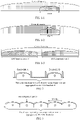
- BWP is introduced. If a rate requirement of the terminal device is very low, a small bandwidth can be configured for the terminal device, as illustrated in FIG. 1-1 , a bandwidth allocation diagram 1. If the rate requirement of the terminal device is high, a slightly larger bandwidth f can be configured for the terminal device, as illustrated in FIG.
- a bandwidth allocation diagram 2 If the terminal device supports a high rate or works in a carrier aggregation (CA) mode, multiple BWPs can be configured for the terminal device, as illustrated in FIG. 1-3 , a bandwidth allocation diagram 3. BWP can also trigger a coexistence of multiple numerologies in a cell.
- CA carrier aggregation
- a terminal device can be configured with up to 4 uplink BWPs and 4 downlink BWPs through dedicated signaling for radio resource control (RRC), but only one uplink BWP and one downlink BWP can be activated at the same time.
- RRC dedicated signaling may also indicate the first activated BWP among the BWPs configured for the terminal device.
- Configuration parameters for each BWP can include:
- the initial first activated BWP is the BWP corresponding to the first activated BWP ID in the RRC signaling.
- the BWP ID is 0 to 4 in the RRC signaling, and 0 is the initial BWP by default.
- a network side uses consecutive BWP IDs when configuring BWPs, as illustrated in the following table.
- Value of BWP indicator field Bandwidth part 2 bits 00 First bandwidth part configured by higher layers 01 Second bandwidth part configured by higher layers 10 Third bandwidth part configured by higher layers 11 Fourth bandwidth part configured by higher layers
- CA Carrier aggregation
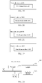
- FIG. 2 A schematic diagram of a carrier aggregation is illustrated in FIG. 2 .
- FIG. 3 Another schematic diagram of a carrier aggregation is illustrated in FIG. 3 .
- CA enables the NR system to support a larger bandwidth by jointly scheduling and using resources on multiple component carriers (CCs), thereby enabling a higher system peak rate.
- CCs component carriers
- PCC primary component carrier
- NAS non-access stratum
- SCC secondary component carrier
- the PCC and the SCC are collectively known as serving cells.
- the standard also specifies that the aggregated carriers support a maximum of 5 carries, that is, the maximum bandwidth after aggregation is 100MHZ, and the aggregated carriers belong to the same network device.
- All aggregated carriers use the same cell-radio network temporary identifier (C-RNTI), and the network device ensures that the C-RNTI does not conflict in the cells where each of the carriers is located. Because both asymmetric carrier aggregation and symmetric carrier aggregation are supported, it is required that the aggregated carriers must have downlink but may not have uplink. For the PCC cell, there must be physical downlink control channel (PDCCH) and PUCCH of the current cell, and only the primary carrier cell has the PUCCH, and other secondary carrier cells may have the PDCCH.
- PDCH physical downlink control channel
- PUCCH physical downlink control channel
- the SCell is configured through RRC dedicated signaling, and the initial configured state is an inactive state in which data transmission and reception cannot be performed. Then, the data transmission and reception can only be performed if the SCell is activated through the MAC CE.
- a schematic diagram of the MAC CE is illustrated in FIG. 4 . From the perspective of SCell configuration and activation delay, such architecture is not an optimal architecture. The delay caused by the state transition reduces the efficiency of CA usage and radio resources, especially in small cell deployment scenarios. In a dense small cell deployment scenario, the signaling load of each SCell is also very large, especially when each SCell needs to be configured separately. Therefore, the current CA architecture introduces additional delay, which restricts the use of CA and reduces the gain of CA load sharing.
- LTE R15 optimizes the CA, and the functions that are mainly optimized are as follows.
- Dormant SCell state States of the SCell include an active state and an inactive state, and in order to realize fast cell recovery, a new cell state is defined, i.e., a dormant state.
- a dormant state the terminal device measures and reports CQI/RRM, but does not decode PDCCH.
- a new MAC CE is defined to control the transition of the dormant state, that is, the transition between the active state and the dormant state.
- a setting of 1 identifies the dormant state, and 0 indicates the active state.
- FIG. 5 A schematic diagram of state transition of SCell in LTE is illustrated in FIG. 5 .
- the activated state and the deactivated state can be converted to each other, the activated state and the dormant state can be converted to each other, the dormant state can be converted to the deactivated state, and the deactivated state cannot be converted to the dormant state.
- the dormant BWP of the SCell is switched to the non-dormant BWP through the DCI to activate the service transmission function of the cell, which has a shorter activation delay and lower complexity compared with the traditional dormant state of the SCell.
- the current standard allows RRC to directly configure the state of the SCell as an activated state and also stipulates that the dormant behavior is a part of the activated SCell state. Therefore, in the current standard, the SCell state is only configured to be the active state through RRC signaling, and it is not clear whether it is the activated SCell state of the dormant behavior or the activated SCell state of the non-dormant behavior.
- the standard agrees that the terminal device can reside on the dormant BWP to realize the dormant behavior, but the standard does not stipulate which BWP the UE will send/receive data on after the terminal device changes from the dormant behavior to the non-dormant activate state.
- GSM global system of mobile communication
- CDMA code division multiple access
- WCDMA wideband code division multiple access
- GPRS general packet radio service
- LTE long term evolution
- LTE frequency division duplex FDD
- TDD LTE time division duplex
- LTE-A advanced long term evolution
- NR new radio
- LTE-U LTE-based access to unlicensed spectrum
- NR-U NR-based access to unlicensed spectrum
- UMTS universal mobile telecommunication system
- WiMAX worldwide interoperability for microwave access
- WLAN wireless local area networks
- WiFi wireless fidelity
- next generation communication system or other communication systems etc.
- D2D device to device
- M2M machine to machine
- MTC machine type communication
- V2V vehicle to vehicle
- the network device involved in embodiments of the present application may be a common base station (such as an NodeB or an eNB or a gNB), a new radio controller (NR controller), a centralized unit, a new radio base station, a remote radio module, a micro base station, a relay, a distributed unit, a transmission reception point (TRP), a transmission point (TP) or any other devices.
- a common base station such as an NodeB or an eNB or a gNB
- NR controller new radio controller
- a centralized unit such as an NodeB or an eNB or a gNB
- a new radio base station such as an a gNB
- NR controller new radio controller
- a centralized unit such as a new radio base station, a remote radio module, a micro base station, a relay, a distributed unit, a transmission reception point (TRP), a transmission point (TP) or any other devices.
- TRP transmission reception point
- TP transmission point
- terminal devices may be terminals of any kind.
- the terminal device may be a user equipment of machine type communication.
- the terminal device may also be referred to as a user equipment (UE), a mobile station (MS), a mobile terminal, a terminal etc.
- the terminal device may communicate with one or more core networks via a radio access network (RAN).
- RAN radio access network
- the terminal device may be a mobile phone (also known as a "cellular" phone), a computer with a mobile terminal etc.
- the terminal device may also be a portable, a pocket-sized, a handheld, a computer built-in or a vehicle on board mobile apparatus, which may exchange language and/or data with the wireless access network.
- the terminal device may not be specifically limited in embodiments of the present application.
- the network device and the terminal device may be deployed on land, whether indoor or outdoor, handheld or vehicle on board.
- the network device and the terminal device may also be deployed on water surface, and may also be deployed on airborne aircraft, balloons and satellites.
- the application scenarios of the network device and the terminal device may not be limited in embodiments of the present application.
- a communication between the network device and the terminal device and a communication between the terminal devices may be carried out through a licensed spectrum, or through an unlicensed spectrum or through both of them.
- the communication between the network device and the terminal device may be conducted in the spectrum below 7 gigahertz (GHz), in the spectrum above 7 GHz, or in both of them.
- GHz gigahertz
- the specific spectrum resource adopted by the communication between the network device and the terminal device may not be limited in embodiments of the present application.
- D2D device to device
- M2M machine to machine
- MTC machine type communication
- V2V vehicle to vehicle
- the communication system 100 may include a network device 110.
- the network device 110 may be a device communicating with a terminal device 120 (or referred to as a communication terminal or a terminal).
- the network device 110 may provide a communication coverage for a specific geographic area, and may communicate with terminal devices located in the coverage area.
- the network device 110 may be a base transceiver station (BTS) of a GSM system or a CDMA system, or a base station (NodeB, NB) of a WCDMA system, or an evolutional base station (Evolutional Node B, eNB or eNodeB) of an LTE system, or a wireless controller of a cloud radio access network (CRAN).
- BTS base transceiver station
- NodeB, NB base station
- Evolutional Node B, eNB or eNodeB evolutional base station
- LTE long term evolutional base station
- the network device may be a mobile switching center, a relay station, an access point, a vehicle on board device, a wearable device, a hub, a switch, a bridge, a router, a network side device of a 5G network, or a network device of a future evolutional public land mobile network (PLMN), etc.
- PLMN public land mobile network
- the communication system 100 may also include at least one terminal device 120 located in the coverage area of the network device 110.
- terminal device may include, but be not limited to: a connection via a wired line, such as via a public switched telephone networks (PSTN), a digital subscriber line (DSL), a digital cable, and a direct cable connection; and/or another data connection/network; and/or via a wireless interface, for example, in a case of a cellular network, a wireless local area networks (WLAN), a digital TV network such as a DVB-H network, a satellite network, an AM- FM broadcast transmitter; and/or an apparatus of another terminal device that is configured to receive/transmit communication signals; and/or an internet of things (IoT) device.
- PSTN public switched telephone networks
- DSL digital subscriber line
- a digital cable and a direct cable connection
- wireless interface for example, in a case of a cellular network, a wireless local area networks (WLAN), a digital TV network such as a DVB-
- a terminal device configured to communicate via a wireless interface may be referred to as a "wireless communication terminal", a “wireless terminal” or a “mobile terminal”.
- the mobile terminal may include but be not limited to: a satellite or cellular phone; a personal communications system (PCS) terminal that combines a cellular radio phone with data processing, fax and data communication capability; a PDA that may include a radio phone, a pager, an Internet/Intranet access, a web browser, a memo pad, a calendar and/or a global positioning system (GPS) receiver; and a conventional laptop and/or palmtop receiver or other electrical apparatuses including a radio telephone transceiver.
- PCS personal communications system
- GPS global positioning system
- the terminal device may refer to an access terminal, a user equipment (UE), a user unit, a user station, a mobile station, a mobile platform, a remote station, a remote terminal, a mobile device, a user terminal, a terminal, a wireless communication device, a user agent or a user apparatus.
- the access terminal may be a cellular phone, a cordless phone, a session initiation protocol (SIP) phone, a wireless local loop (WLL) station, a personal digital assistant (PDA), and a handheld device with wireless communication function, a computing device or other processing devices connecting to wireless modems, a vehicle on board device, a wearable device, a terminal device in a 5G network, or a terminal device in the future evolutional PLMN, etc.
- SIP session initiation protocol
- WLL wireless local loop
- PDA personal digital assistant
- a Device to Device (D2D) communication may be performed between terminal devices 120.
- D2D Device to Device
- the 5G system or the 5G network may also be referred to as a new radio (NR) system or a NR network.
- NR new radio
- FIG. 6 illustrates a network device and two terminal devices as an example.
- the communication system 100 may include multiple network devices and the coverage area of each network device may include different numbers of terminal devices, which is not limited in embodiments of the present application.
- the communication system 100 may also include other network entities, such as a network controller, a mobile management entity, which are not limited in embodiments of the present application.
- network entities such as a network controller, a mobile management entity, which are not limited in embodiments of the present application.
- the communication device may include a network device 110 and a terminal device 120 with communication functions.
- the network device 110 and the terminal device 120 may be specific devices described above, which will not be repeated here again.
- the communication device may also include other devices in the communication system 100, for example, other network entities such as a network controller or a mobile management entity, which is not limited in embodiments of the present application.
- Step S201 When a terminal device switches to a dormant BWP or a non-dormant BWP, the terminal device starts a first timer, stops the first timer, or restarts the first timer.
- the first timer is used for switching the BWP state, for example, the first timer is used for switching from a dormant BWP to a non-dormant BWP, or the first timer is used for switching from a non-dormant BWP to a dormant BWP.
- the method may further include: the terminal device receiving a first indication information sent by a network device, wherein the first indication information is used to indicate whether the terminal device switches to the non-dormant BWP. If the first indication information indicates the terminal device to switch to the non-dormant BWP, the terminal device enters the non-dormant BWP.
- the first indication information is further used to indicate whether to use the first timer on the non-dormant BWP. In the case that the terminal device has entered a non-dormant BWP according to the first indication information, if the first indication information indicates that the first timer is used on the non-dormant BWP, the terminal device starts the first timer, or the terminal device restarts the first timer.
- the terminal device switches to the dormant BWP; or the terminal device switches from the non-dormant BWP to the dormant BWP according to the first indication information sent by the network device; or the terminal device switches from the non-dormant BWP to a default BWP according to the first indication information sent by the network device.
- the first timer is restarted.
- the data transmission comprises at least one of the followings: the terminal device receiving a schedule sent by a network device, the terminal device sending data, and the terminal device receiving data.
- the terminal device in the case that the terminal device has entered a non-dormant BWP according to the first indication information, if the first indication information indicates that the first timer is not used on the non-dormant BWP, the terminal device prohibits starting the first timer, or the terminal device stops the running first timer.
- the first timer may be a BWP inactivity timer (bwp-InactivityTimer), and the first timer may also be a timer for controlling the transition of the state of a SCell from the active state of the non-dormant behavior to the active state of the dormant behavior.
- bwp-InactivityTimer BWP inactivity timer
- the first indication information may be carried in an RRC dedicated signaling.
- the method may further include: the terminal device receiving a second indication information sent by the network device, wherein the second indication information is used to indicate whether the terminal device is switch to the non-dormant BWP. If the second indication information indicates the terminal device to switch to the non-dormant BWP, the terminal device enters the non-dormant BWP.
- the second indication information is further used to indicate whether to use the first timer on the dormant BWP.
- the terminal device has entered the dormant BWP according to the second indication information
- the terminal device starts the first timer, or the terminal device restarts the first timer.
- the terminal device switches to a first BWP.
- the first BWP may be the first activated BWP configured by the network device, or the non-dormant BWP configured by the network device, or the BWP of the latest service; the first activated BWP may be the first activated BWP configured by the network device.
- the terminal device in the case that the terminal device has entered the dormant BWP according to the first indication information, if the second indication information indicates that the first timer is not used on the dormant BWP, the terminal device prohibits starting the first timer, or the terminal device stops the running first timer.
- the first timer may be a timer for controlling the transition of the state of the SCell from the active state of dormant behavior to the active state of non-dormant behavior.
- the second indication information may be carried in an RRC dedicated signaling.
- An embodiment of the present application provides an optional processing flow of a method for controlling an uplink behavior of a terminal device, as illustrated in FIG. 8 , including the following steps: Step S301: When a SCell accessed by the terminal device enters an active state of a dormant behavior, the terminal device determines an uplink behavior of the terminal device according to a configuration information sent by a network device.
- the terminal device switches to the currently activated uplink BWP; or the terminal device switches to the first uplink activated BWP configured by the network device; or the terminal device switches to the uplink initial BWP; or the terminal device switches to the BWP with the smallest BWP ID; or the terminal device switches to the BWP with the largest BWP ID.
- the configuration information includes dormant downlink BWP and does not include dormant uplink BWP.
- the terminal device enters the dormant BWP according to the indication information sent by the network device, and the terminal device enters the dormant downlink BWP on the SCell.
- the terminal device enters the currently activated uplink BWP in the uplink direction, or the terminal device enters the first uplink activated BWP configured by the network device in the uplink direction, or the terminal device enters the uplink initial BWP in the uplink direction, or the terminal device enters the BWP with the smallest BWP ID in the uplink direction, or the terminal device enters the BWP with the largest BWP ID in the uplink direction.
- the configuration information may be carried in RRC dedicated signaling.
- the terminal device is prohibited from sending data and/or uplink signals on the uplink BWP regardless of which BWP the terminal device enters in the uplink direction.
- the data may include: an uplink shared channel (physical uplink shared channel, PUSCH); the uplink signal may include: a sounding reference signal (SRS).
- SRS sounding reference signal
- Step S401 When a state of a SCell accessed by a terminal device is an active state of a dormant behavior, the terminal device stops running a second timer, starts the second timer, or restarts the second timer.
- the terminal device when the state of the SCell accessed by the terminal device is the active state of the dormant behavior, the terminal device switches to the dormant BWP.
- the method further includes: the terminal device receiving a third indication information sent by the network device.
- the third indication information is used to indicate whether the SCell accessed by the terminal device enters the active state of dormancy behavior, and/or whether the second timer is used when the state of the SCell is the active state of dormant behavior.
- the terminal device stops running the second timer, and the terminal device is prohibited from starting the second timer.
- the second timer is used when the third indication information indicates that the state of the SCell is the active state of the dormant behavior, if the terminal device enters the dormant BWP according to the third indication information, and the state of the SCell is the active state of the dormant behavior, the terminal device starts the second timer, or continues to run the second timer, or restarts the second timer. If the second timer expires, the SCell enters a deactivated state.
- the second timer is a SCell deactivation timer, or the second timer is a timer used to control the transition of the state of the SCell from the active state of the dormant behavior to the deactivated state.
- the third indication information may be carried in an RRC dedicated signaling.
- An optional processing flow of a secondary cell group configuration method includes the following steps: S501: A terminal device receiving a first configuration information sent by a network device, wherein the first configuration information comprises at least one dormant secondary cell (SCell) group, and the at least one dormant SCell group comprises at least one SCell.
- SCell dormant secondary cell
- each of the dormant SCell groups is associated with a group that represents a group ID.
- the at least one dormant SCell group constitutes a dormant SCell group set, and the dormant SCell group set is associated with a group set ID.
- the dormant SCell group sets there is no identical dormant SCell among the dormant SCell groups.
- each SCell is associated with at least one dormant SCell group set ID; and/or each SCell is associated with at least one group ID.
- a schematic diagram of allocation of secondary cell groups as illustrated in FIG. 11 , all the dormant SCell groups belong to a dormant SCell group set; or all the dormant SCell groups have a same group assignment.
- One dormant SCell in one dormant SCell group set may belong to two or more dormant SCell groups.
- each of the dormant SCell groups belongs to one in at least one dormant SCell group set; or each of the dormant SCell groups has at least one group assignment. It can be understood that, there are two or more group assignments for dormant SCell groups for dormant SCells, and a dormant SCell group set has one group assignment for dormant SCell group.
- the first configuration information is carried in an RRC dedicated signaling, for example, the first configuration information is carried in a first RRC dedicated signaling.
- the related protocol can be described as:
- Step S601 A terminal device receiving a second RRC dedicated signaling sent by a network device, wherein the second RRC dedicated signaling comprises at least one first BWP, and each of the at least one first BWP is associated with a first BWP ID.
- the second RRC dedicated signaling further comprises a dormant BWP.
- the second RRC dedicated signaling further comprises a dormant BWP ID.
- the dormant BWP ID is associated with one first BWP ID and is used to indicate the dormant BWP in the at least one first BWP.
- an indication of the dormant BWP in the at least one first BWP is configured in a serving cell configuration IE of each cell in a cell group configuration in an RRC reconfiguration message.
- a configuration of each first BWP carries one second indication information, and the second indication information is used to indicate whether a corresponding second BWP is the dormant BWP.
- a first parameter of the dormant BWP is configured by default, and the first parameter configured by default is used to indicate the dormant BWP.
- the first parameter comprises: a downlink control channel (physical downlink control channel, PDCCH) configuration parameter, and/or a downlink shared channel (physical downlink control channel, PDSCH) configuration parameter.
- the second RRC dedicated signaling includes 5 BWPs, one of which has a default PDCCH configuration parameter, and the BWP of the default PDCCH configuration parameter is the dormant BWP.
- the second RRC dedicated signaling comprises one dormant BWP, the dormant BWP has no corresponding dormant BWP ID, and/or a second parameter of the dormant BWP is configured by default, the second parameter configured by default is used to indicate the dormant BWP.
- the second parameter comprises: a PDCCH configuration parameter, and/or a PDSCH configuration parameter.
- the related protocol can be described as:
- a composition structure diagram 1 of the terminal device is illustrated in FIG. 14 .
- a terminal device 800 includes: a first processor 801, wherein when the terminal device switches to a dormant BWP or a non-dormant BWP, the first processor starts a first timer, stops the first timer, or restarts the first timer.
- the first processor 801 restarts the first timer.
- the data transmission comprises at least one of the followings: receiving a schedule sent by a network device; sending data; and receiving data.
- the first processor 801 switches from the non-dormant BWP to the dormant BWP or the first processor 801 switches from the dormant BWP to the non-dormant BWP.
- the first processor 801 switches from the non-dormant BWP to the dormant BWP, or from the non-dormant BWP to a default BWP, according to a first indication information sent by a network device.
- the terminal device further comprises: a first receiver 802 configured to receive a first indication information sent by a network device; wherein the first indication information is used to indicate whether the terminal device switches to the dormant BWP or the non-dormant BWP, and/or the first indication information is used to indicate whether to use the first timer on the non-dormant BWP.
- the first processor 801 switches from the dormant BWP to a first BWP.
- the first BWP is a first activated BWP configured by a network device, or the non-dormant BWP configured by the network device, or a BWP of a latest service.
- the terminal device further comprises: a second receiver 803 configured to receive a second indication information sent by a network device, where the second indication information is used to indicate whether the terminal device switches to the non-dormant BWP, and/or the second indication information is used to indicate whether to use the first timer on the dormant BWP.
- the first timer is a BWP inactivity timer, or the first timer is a timer used to control a transition of a state of a SCell from an active state of a non-dormant behavior to an active state of a dormant behavior, or the first timer is a timer used to control a transition of a state of the SCell from the active state of the dormant behavior to the active state of the non-dormant behavior.
- a composition structure diagram 2 of the terminal device is illustrated in FIG. 15 .
- a terminal device 900 includes: a second processor 901, wherein when a SCell accessed by the terminal device enters an active state of a dormant behavior, the terminal device determines an uplink behavior of the terminal device according to a configuration information sent by a network device.
- the configuration information does not comprise a dormant uplink BWP, and the terminal device remains in a currently activated uplink BWP; or the terminal device switches to a first uplink activated BWP configured by the network device; or the terminal device switches to an uplink initial BWP; or the terminal device switches to a BWP with a smallest BWP identifier (ID); or the terminal device switches to a BWP with a largest BWP ID.
- ID BWP identifier
- the second processor 901 is configured to prohibit a transmission of data and/or an uplink signal on an uplink BWP; and/or the second processor 901 is configured to suspend or clear a configured authorized resource.
- the data comprises an uplink shared channel (PUSCH); and/or the uplink signal comprises an SRS.
- PUSCH uplink shared channel
- SRS uplink signal
- a composition structure diagram 3 of the terminal device is illustrated in FIG. 16 .
- a terminal device 1000 includes: a third processor 1001, wherein when a state of a SCell accessed by a terminal device is an active state of a dormant behavior, the terminal device stops running a second timer, starts the second timer, or restarts the second timer.
- the third processor 1001 is configured to switch to a dormant BWP.
- the terminal device 1000 further comprises: a third receiver 1002 configured to receive a third indication information sent by a network device; wherein the third indication information is used to indicate whether the SCell accessed by the terminal device enters the active state of the dormant behavior, and/or whether to use the second timer when the state of the SCell is the active state of the dormant behavior.
- the third indication information indicates that the second timer is not used when the state of the SCell is the active state of the dormant behavior, the third processor 1001 stops running the second timer.
- the third indication information indicates that the second timer is used when the state of the SCell is the active state of the dormant behavior, the third processor 1001 starts the second timer, continues to run the second timer, or restarts the second timer.
- the SCell when the second timer expires, the SCell enters a deactivated state.
- the second timer is an SCell deactivation timer, or the second timer is a timer used to control a transition of the state of the SCell from the active state of the dormant behavior to a deactivated state.
- a composition structure diagram 4 of the terminal device is illustrated in FIG. 17 .
- a terminal device 2000 includes: a fourth receiver 2001 configured to receive a first configuration information sent by a network device, wherein the first configuration information comprises at least one dormant SCell group, and the at least one dormant SCell group comprises at least one SCell.
- all the dormant SCell groups belong to a dormant SCell group set; or all the dormant SCell groups have a same group assignment.
- each of the dormant SCell groups belongs to one in at least one dormant SCell group set; or each of the dormant SCell groups has at least one group assignment.
- each of the dormant SCell groups is associated with a group that represents a group ID.
- the at least one dormant SCell group constitutes a dormant SCell group set, and the dormant SCell group set is associated with a group set ID.
- each of the dormant SCell group sets there is no identical dormant SCell among the dormant SCell groups.
- each SCell is associated with at least one dormant SCell group set ID; and/or each SCell is associated with at least one group ID.
- the first configuration information is carried in a first RRC dedicated signaling.
- a composition structure diagram 5 of the terminal device is illustrated in FIG. 18 .
- a terminal device 3000 includes: a fifth receiver 3001 configured to receive a second RRC dedicated signaling sent by a network device, wherein the second RRC dedicated signaling comprises at least one first BWP, and each of the at least one first BWP is associated with a first BWP identifier (ID).
- ID a first BWP identifier
- the second RRC dedicated signaling further comprises a dormant BWP.
- the second RRC dedicated signaling further comprises a dormant BWP ID.
- the dormant BWP ID is associated with one first BWP ID and is used to indicate the dormant BWP in the at least one first BWP.
- an indication of the dormant BWP in the at least one first BWP is configured in a serving cell configuration IE of each cell in a cell group configuration in an RRC reconfiguration message.
- a configuration of each first BWP carries one second indication information, and the second indication information is used to indicate whether a corresponding second BWP is the dormant BWP.
- a first parameter of the dormant BWP is configured by default, and the first parameter configured by default is used to indicate the dormant BWP.
- the first parameter comprises: a PDCCH configuration parameter, and/or a PDSCH configuration parameter.
- the second RRC dedicated signaling further comprises one dormant BWP; the dormant BWP has no corresponding dormant BWP ID, and/or a second parameter of the dormant BWP is configured by default, the second parameter configured by default is used to indicate the dormant BWP.
- the second parameter comprises: a PDCCH configuration parameter, and/or a PDSCH configuration parameter.
- a composition structure diagram 1 of the network device is illustrated in FIG. 19 .
- a terminal device 4000 includes: a first transmitter 4001 configured to send a first indication information to a terminal device, wherein the first indication information is used to indicate whether to use a first timer when a state of a SCell accessed by the terminal device is an active state of a dormant behavior or an active state of a non-dormant behavior.
- the first indication information is further used to indicate the terminal device to switch from a non-dormant BWP to a dormant BWP, or to switch from the non-dormant BWP to a default BWP.
- the first timer is a BWP inactivity timer, or the first timer is a timer used to control a transition of the state of the SCell from the active state of the non-dormant behavior to the dormant behavior.
- the first indication information is further used to indicate whether the terminal device switches to a dormant BWP or a non-dormant BWP; and/or the first indication information is used to indicate whether to use the first timer on the non-dormant BWP or the dormant BWP.
- An embodiment of the present application further provides a network device.
- a composition structure diagram 2 of the network device is illustrated in FIG. 20 .
- a terminal device 5000 includes: a second transmitter 5001 configured to send a first indication information to a terminal device, wherein the first indication information is used to indicate whether to use a second timer when a state of a SCell is an active state of a dormant behavior.
- the first indication information is further used to indicate whether the SCell accessed by the terminal device enters the active state of the dormant behavior.
- a composition structure diagram 3 of the network device is illustrated in FIG. 21 .
- a terminal device 6000 includes: a third transmitter 6001 configured to send a first configuration information to a terminal device, wherein the first configuration information comprises at least one dormant SCell group, and the at least one dormant SCell group comprises at least one SCell.
- all the dormant SCell groups belong to a dormant SCell group set; or all the dormant SCell groups have a same group assignment.
- each of the dormant SCell groups belongs to one in at least one dormant SCell group set; or each of the dormant SCell groups has at least one group assignment.
- each of the dormant SCell groups is associated with a group that represents a group ID.
- the at least one dormant SCell group constitutes a dormant SCell group set, and the dormant SCell group set is associated with a group set ID.
- each of the dormant SCell group sets there is no identical dormant SCell among the dormant SCell groups.
- each SCell is associated with at least one dormant SCell group set ID; and/or each SCell is associated with at least one group ID.
- the first configuration information is carried in a first RRC dedicated signaling.
- a composition structure diagram 4 of the network device is illustrated in FIG. 22 .
- a terminal device 7000 includes: a fourth transmitter 7001 configured to send a second RRC dedicated signaling to a terminal device, wherein the second RRC dedicated signaling comprises at least one first BWP, and each of the at least one first BWP is associated with a first BWP identifier (ID).
- ID a first BWP identifier
- the second RRC dedicated signaling further comprises a dormant BWP.
- the second RRC dedicated signaling further comprises a dormant BWP ID.
- the dormant BWP ID is associated with one first BWP ID and is used to indicate the dormant BWP in the at least one first BWP.
- an indication of the dormant BWP in the at least one first BWP is configured in a serving cell configuration IE of each cell in a cell group configuration in an RRC reconfiguration message.
- a configuration of each first BWP carries one second indication information, and the second indication information is used to indicate whether a corresponding second BWP is the dormant BWP.
- a first parameter of the dormant BWP is configured by default, and the first parameter configured by default is used to indicate the dormant BWP.
- the first parameter comprises: a PDCCH configuration parameter, and/or a PDSCH configuration parameter.
- the second RRC dedicated signaling further comprises one dormant BWP; the dormant BWP has no corresponding dormant BWP ID, and/or a second parameter of the dormant BWP is configured by default, the second parameter configured by default is used to indicate the dormant BWP.
- the second parameter comprises: a PDCCH configuration parameter, and/or a PDSCH configuration parameter.
- An embodiment of the present application further provides a terminal device comprising a processor and a memory configured to store a computer program executable on the processor, wherein the processor is configured to, when running the computer program, perform steps of the timer control method, the method for controlling the uplink behavior of the terminal device, the secondary cell group configuration method, or the bandwidth part configuration method performed by the aforesaid terminal device.
- An embodiment of the present application further provides a network device comprising a processor and a memory configured to store a computer program executable on the processor, wherein the processor is configured to, when running the computer program, perform steps of the timer control method, the secondary cell group configuration method, or the bandwidth part configuration method performed by the aforesaid network device.
- An embodiment of the present application further provides a chip comprising a processor for calling and running a computer program from a memory, so that a device installed with the chip performs the timer control method, the method for controlling the uplink behavior of the terminal device, the secondary cell group configuration method, or the bandwidth part configuration method performed by the aforesaid terminal device.
- An embodiment of the present application further provides a chip comprising a processor for calling and running a computer program from a memory, so that a device installed with the chip performs the timer control method, the secondary cell group configuration method, or the bandwidth part configuration method performed by the aforesaid network device.
- An embodiment of the present application further provides a storage medium storing an executable program, the executable program, when executed by a processor, implements the timer control method, the method for controlling the uplink behavior of the terminal device, wherein the secondary cell group configuration method, or the bandwidth part configuration method performed by the aforesaid terminal device.
- An embodiment of the present application further provides a storage medium storing an executable program, wherein the executable program, when executed by a processor, implements the timer control method, the secondary cell group configuration method, or the bandwidth part configuration method performed by the aforesaid network device.
- An embodiment of the present application further provides a computer program product comprising a computer program instruction, wherein the computer program instruction causes a computer to perform the timer control method, the method for controlling the uplink behavior of the terminal device, the secondary cell group configuration method, or the bandwidth part configuration method performed by the aforesaid terminal device.
- An embodiment of the present application further provides a computer program product comprising a computer program instruction, wherein the computer program instruction causes a computer to perform the timer control method, the secondary cell group configuration method, or the bandwidth part configuration method performed by the aforesaid network device.
- An embodiment of the present application further provides a computer program, wherein the computer program causes a computer to perform the timer control method, the method for controlling the uplink behavior of the terminal device, the secondary cell group configuration method, or the bandwidth part configuration method performed by the aforesaid terminal device.
- An embodiment of the present application further provides a computer program, wherein the computer program causes a computer to perform the timer control method, the secondary cell group configuration method, or the bandwidth part configuration method performed by the aforesaid network device.
- FIG. 23 is a hardware composition structure diagram of an electronic device (UE or a network device) according to an embodiment of the present application.
- the electronic device 700 includes at least one processor 701, a memory 702 and at least one network interface 704. Each component in the electronic device 700 is coupled together through a bus system 705. It can be understood that the bus system 705 is used to implement connection communication between these components.
- the bus system 705 includes a data bus and further includes a power bus, a control bus and a state signal bus. However, for clear description, various buses in FIG. 23 are marked as the bus system 705.
- the memory 702 may be a volatile memory or a nonvolatile memory, and may also include both of the volatile and nonvolatile memories.
- the nonvolatile memory may be a read only memory (ROM), a programmable read-only memory (PROM), an erasable programmable read-only memory (EPROM), an electrically erasable programmable read-only memory (EEPROM), a ferromagnetic random access memory (FRAM), a flash memory, a magnetic surface memory, a compact disc or a compact disc read-only memory (CD-ROM).
- the magnetic surface memory may be a disk memory or a tape memory.
- the volatile memory may be a random access memory (RAM), and is used as an external high-speed cache.
- RAMs in various forms may be adopted, such as a static random access memory (SRAM), a synchronous static random access memory (SSRAM), a dynamic random access memory (DRAM), a synchronous dynamic random access memory (SDRAM), a double data rate synchronous dynamic random access memory (DDRSDRAM), an enhanced synchronous dynamic random access memory (ESDRAM), a syncLink dynamic random access memory (SLDRAM) and a direct rambus random access memory (DRRAM).
- SRAM static random access memory
- SSRAM synchronous static random access memory
- DRAM dynamic random access memory
- SDRAM synchronous dynamic random access memory
- DDRSDRAM double data rate synchronous dynamic random access memory
- ESDRAM enhanced synchronous dynamic random access memory
- SLDRAM syncLink dynamic random access memory
- DRRAM direct rambus random access memory
- the memory 702 is configured to store various types of data to support the operation of the electronic device 700.
- Examples of the data include any computer program, for example, an application program 7022, operated in the electronic device 700.
- a program for implementing the method in the embodiments of the present application may be included in the application program 7022.
- the method disclosed in the embodiments of the present application may be applied to the processor 701 or implemented by the processor 701.
- the processor 701 may be an integrated circuit chip with a signal processing capability. In an implementation process, each step of the method may be completed by an integrated logic circuit in a hardware form in the processor 701 or an instruction in a software form.
- the processor 701 may be a universal processor, a digital signal processor (DSP) or another programmable logic device (PLD), a discrete gate or transistor logic device, a discrete hardware component and the like.
- the processor 701 may be configured to implement or execute each method, step and logical block diagram disclosed in the embodiments of the present application.
- the universal processor may be a microprocessor, any conventional processor or the like.
- the steps of the method disclosed in combination with the embodiments of the present application may be directly embodied to be executed and completed by a hardware decoding processor or executed and completed by a combination of software modules and the hardware in the decoding processor.
- the software module may be located in a storage medium, and the storage medium is located in the memory 702.
- the processor 701 reads information in the memory 702 and completes the steps of the method in combination with the hardware thereof.
- the electronic device 700 may be implemented by one or more application specific integrated circuits (ASICs), DSPs, PLDs, complex programmable logic devices (CPLDs), field programmable gate arrays (FPGAs), universal processors, controllers, micro controller units (MCUs), microprocessor units (MPUs) or other electronic components, and is configured to execute the abovementioned method.
- ASICs application specific integrated circuits
- DSPs digital signal processors
- CPLDs complex programmable logic devices
- FPGAs field programmable gate arrays
- controllers controllers
- MCUs micro controller units
- MPUs microprocessor units
- the embodiments of the present application also provide a storage medium, which is configured to store a computer program.
- the storage medium may be applied to UE in the embodiments of the present application, and the computer program enables a computer to execute corresponding flows in each method in the embodiments of the present application.
- the computer program enables a computer to execute corresponding flows in each method in the embodiments of the present application.
- These computer program instructions may be provided for a universal computer, a dedicated computer, an embedded processor or a processor of another programmable data processing device to generate a machine, so that a device for implementing a function specified in one flow or multiple flows in the flowcharts and/or one block or multiple blocks in the block diagrams is generated by the instructions executed through the computer or the processor of the other programmable data processing device.
- These computer program instructions may also be stored in a computer-readable memory capable of guiding the computer or the other programmable data processing device to work in a specific manner, so that a product including instruction means may be generated by the instructions stored in the computer-readable memory.
- the instruction means is used to implement the function specified in one flow or multiple flows in the flowcharts and/or one block or multiple blocks in the block diagrams.
- These computer program instructions may further be loaded onto the computer or the other programmable data processing device, so that a series of operating steps are executed on the computer or the other programmable data processing device to generate processing implemented by the computer, and steps for implementing the function specified in one flow or multiple flows in the flowcharts and/or one block or multiple blocks in the block diagrams are provided by the instructions executed on the computer or the other programmable data processing device.
Landscapes
- Engineering & Computer Science (AREA)
- Signal Processing (AREA)
- Computer Networks & Wireless Communication (AREA)
- Mobile Radio Communication Systems (AREA)
Applications Claiming Priority (1)
| Application Number | Priority Date | Filing Date | Title |
|---|---|---|---|
| PCT/CN2019/122462 WO2021108958A1 (fr) | 2019-12-02 | 2019-12-02 | Procédé de commande de temporisateur, procédé de configuration, dispositif électronique et support de stockage |
Publications (2)
| Publication Number | Publication Date |
|---|---|
| EP4030652A1 true EP4030652A1 (fr) | 2022-07-20 |
| EP4030652A4 EP4030652A4 (fr) | 2023-03-29 |
Family
ID=76221306
Family Applications (1)
| Application Number | Title | Priority Date | Filing Date |
|---|---|---|---|
| EP19954821.5A Ceased EP4030652A4 (fr) | 2019-12-02 | 2019-12-02 | Procédé de commande de temporisateur, procédé de configuration, dispositif électronique et support de stockage |
Country Status (4)
| Country | Link |
|---|---|
| US (1) | US12167492B2 (fr) |
| EP (1) | EP4030652A4 (fr) |
| CN (2) | CN113207321A (fr) |
| WO (1) | WO2021108958A1 (fr) |
Families Citing this family (2)
| Publication number | Priority date | Publication date | Assignee | Title |
|---|---|---|---|---|
| CN113329449B (zh) * | 2019-05-30 | 2023-05-12 | Oppo广东移动通信有限公司 | 一种bwp的管理方法及装置、终端 |
| KR102918446B1 (ko) | 2020-02-11 | 2026-01-28 | 삼성전자 주식회사 | 차세대 이동 통신 시스템에서 휴면 부분 대역폭을 관리하는 방법 및 장치 |
Family Cites Families (13)
| Publication number | Priority date | Publication date | Assignee | Title |
|---|---|---|---|---|
| WO2015180299A1 (fr) * | 2014-05-27 | 2015-12-03 | 中兴通讯股份有限公司 | Procédé de traitement de signal de découverte et station de base |
| CN106470436A (zh) | 2015-08-19 | 2017-03-01 | 中国移动通信集团江苏有限公司 | 一种确定非激活定时器时长的方法及网络侧设备 |
| EP3611866A1 (fr) * | 2017-10-26 | 2020-02-19 | Ofinno, LLC | Rapport de puissance reçue de signal de référence |
| CN110012499B (zh) * | 2018-01-04 | 2022-07-12 | 株式会社Kt | 用于控制SCell状态的方法及其装置 |
| CN110011752B (zh) * | 2018-01-04 | 2021-10-22 | 维沃移动通信有限公司 | 一种cqi上报方法、终端设备及网络设备 |
| CN110324890B (zh) * | 2018-03-30 | 2022-05-17 | 维沃移动通信有限公司 | 部分带宽激活定时器的控制方法及终端 |
| CN109496447B (zh) * | 2018-10-19 | 2022-07-15 | 北京小米移动软件有限公司 | 定时器配置方法及装置 |
| WO2020159227A1 (fr) * | 2019-01-29 | 2020-08-06 | Samsung Electronics Co., Ltd. | Procédé et appareil pour améliorer l'agrégation de porteuse dans un système de communication mobile de nouvelle génération |
| KR102854552B1 (ko) * | 2019-02-13 | 2025-09-02 | 삼성전자주식회사 | 무선 통신 시스템에서 캐리어 어그리게이션을 지원하기 위한 방법 및 장치 |
| US11363625B2 (en) * | 2019-03-28 | 2022-06-14 | Ofinno, Llc | Bandwidth part operation in new radio |
| PT3845011T (pt) * | 2019-03-28 | 2023-09-27 | Ofinno Llc | Bwp ativa de poupança de energia |
| CN110519853B (zh) * | 2019-09-06 | 2023-04-28 | 中兴通讯股份有限公司 | 切换指示方法、切换方法、装置、服务节点、终端及介质 |
| EP4140235A4 (fr) * | 2020-07-14 | 2023-10-18 | Samsung Electronics Co., Ltd. | Procédé et appareil pour commander l'activation d'un groupe de cellules dans un système de communication sans fil |
-
2019
- 2019-12-02 WO PCT/CN2019/122462 patent/WO2021108958A1/fr not_active Ceased
- 2019-12-02 EP EP19954821.5A patent/EP4030652A4/fr not_active Ceased
- 2019-12-02 CN CN201980081584.0A patent/CN113207321A/zh not_active Withdrawn
- 2019-12-02 CN CN202110887716.8A patent/CN113490229B/zh active Active
-
2022
- 2022-02-18 US US17/675,499 patent/US12167492B2/en active Active
Also Published As
| Publication number | Publication date |
|---|---|
| CN113490229B (zh) | 2023-06-27 |
| US20220174776A1 (en) | 2022-06-02 |
| CN113490229A (zh) | 2021-10-08 |
| WO2021108958A1 (fr) | 2021-06-10 |
| CN113207321A (zh) | 2021-08-03 |
| EP4030652A4 (fr) | 2023-03-29 |
| US12167492B2 (en) | 2024-12-10 |
Similar Documents
| Publication | Publication Date | Title |
|---|---|---|
| US12323368B2 (en) | Method and device for managing band width part | |
| US11751278B2 (en) | Cell state management method and apparatus, terminal device, and network device | |
| US12439419B2 (en) | Channel monitoring method, electronic device, and storage medium | |
| US12167335B2 (en) | Discontinuous reception method, electronic device and storage medium | |
| US20220352923A1 (en) | Frequency hopping methods, electronic device, and storage medium | |
| WO2021087675A1 (fr) | Procédé de surveillance d'un signal de réveil, dispositif électronique et support de stockage | |
| WO2020248143A1 (fr) | Procédé de commande de puissance, dispositif terminal et dispositif de réseau | |
| WO2021097698A1 (fr) | Procédé d'accès en liaison montante, dispositif électronique et support de stockage | |
| WO2021128210A1 (fr) | Procédé de mesure, appareil électronique et support de stockage | |
| CN115280845B (zh) | 一种小区切换方法、电子设备及存储介质 | |
| WO2021030928A1 (fr) | Procédé de commande de mesures, dispositif électronique et support de stockage | |
| US12507138B2 (en) | Cell accessing method, electronic device, and storage medium | |
| US12167492B2 (en) | Timer control method, configuration method, electronic device, and storage medium | |
| WO2021232377A1 (fr) | Procédé de configuration pour une réception discontinue, dispositif électronique et support de stockage | |
| CN116097804B (zh) | 一种信号传输方法、电子设备及存储介质 | |
| CN114600511B (zh) | 控制小区状态的方法及装置、终端设备、网络设备 | |
| EP4057545B1 (fr) | Procédé et appareil de rétroaction, dispositif terminal et dispositif réseau | |
| US20230363007A1 (en) | Methods for channel transmission and terminal device | |
| CN115426092B (zh) | 一种非连续接收持续定时器控制方法、电子设备及存储介质 | |
| CN115767727A (zh) | 一种数据传输方法、电子设备及存储介质 |
Legal Events
| Date | Code | Title | Description |
|---|---|---|---|
| STAA | Information on the status of an ep patent application or granted ep patent |
Free format text: STATUS: THE INTERNATIONAL PUBLICATION HAS BEEN MADE |
|
| PUAI | Public reference made under article 153(3) epc to a published international application that has entered the european phase |
Free format text: ORIGINAL CODE: 0009012 |
|
| STAA | Information on the status of an ep patent application or granted ep patent |
Free format text: STATUS: REQUEST FOR EXAMINATION WAS MADE |
|
| 17P | Request for examination filed |
Effective date: 20220221 |
|
| AK | Designated contracting states |
Kind code of ref document: A1 Designated state(s): AL AT BE BG CH CY CZ DE DK EE ES FI FR GB GR HR HU IE IS IT LI LT LU LV MC MK MT NL NO PL PT RO RS SE SI SK SM TR |
|
| REG | Reference to a national code |
Ref country code: DE Ref legal event code: R079 Free format text: PREVIOUS MAIN CLASS: H04L0001000000 Ipc: H04L0005000000 |
|
| RIC1 | Information provided on ipc code assigned before grant |
Ipc: H04W 52/02 20090101ALI20221104BHEP Ipc: H04W 76/27 20180101ALI20221104BHEP Ipc: H04W 76/15 20180101ALI20221104BHEP Ipc: H04L 1/00 20060101ALI20221104BHEP Ipc: H04L 5/00 20060101AFI20221104BHEP |
|
| DAV | Request for validation of the european patent (deleted) | ||
| DAX | Request for extension of the european patent (deleted) | ||
| A4 | Supplementary search report drawn up and despatched |
Effective date: 20230224 |
|
| RIC1 | Information provided on ipc code assigned before grant |
Ipc: H04W 52/02 20090101ALI20230220BHEP Ipc: H04W 76/27 20180101ALI20230220BHEP Ipc: H04W 76/15 20180101ALI20230220BHEP Ipc: H04L 1/00 20060101ALI20230220BHEP Ipc: H04L 5/00 20060101AFI20230220BHEP |
|
| STAA | Information on the status of an ep patent application or granted ep patent |
Free format text: STATUS: EXAMINATION IS IN PROGRESS |
|
| 17Q | First examination report despatched |
Effective date: 20231024 |
|
| REG | Reference to a national code |
Ref country code: DE Ref legal event code: R003 |
|
| STAA | Information on the status of an ep patent application or granted ep patent |
Free format text: STATUS: THE APPLICATION HAS BEEN REFUSED |
|
| 18R | Application refused |
Effective date: 20250115 |