EP4030869A1 - Terminal et procédé de communication - Google Patents
Terminal et procédé de communication Download PDFInfo
- Publication number
- EP4030869A1 EP4030869A1 EP19945167.5A EP19945167A EP4030869A1 EP 4030869 A1 EP4030869 A1 EP 4030869A1 EP 19945167 A EP19945167 A EP 19945167A EP 4030869 A1 EP4030869 A1 EP 4030869A1
- Authority
- EP
- European Patent Office
- Prior art keywords
- terminal
- harq
- ack
- base station
- feedback
- Prior art date
- Legal status (The legal status is an assumption and is not a legal conclusion. Google has not performed a legal analysis and makes no representation as to the accuracy of the status listed.)
- Pending
Links
Images


Classifications
-
- H—ELECTRICITY
- H04—ELECTRIC COMMUNICATION TECHNIQUE
- H04L—TRANSMISSION OF DIGITAL INFORMATION, e.g. TELEGRAPHIC COMMUNICATION
- H04L1/00—Arrangements for detecting or preventing errors in the information received
- H04L1/12—Arrangements for detecting or preventing errors in the information received by using return channel
- H04L1/16—Arrangements for detecting or preventing errors in the information received by using return channel in which the return channel carries supervisory signals, e.g. repetition request signals
- H04L1/18—Automatic repetition systems, e.g. Van Duuren systems
- H04L1/1825—Adaptation of specific ARQ protocol parameters according to transmission conditions
-
- H—ELECTRICITY
- H04—ELECTRIC COMMUNICATION TECHNIQUE
- H04W—WIRELESS COMMUNICATION NETWORKS
- H04W72/00—Local resource management
- H04W72/02—Selection of wireless resources by user or terminal
-
- H—ELECTRICITY
- H04—ELECTRIC COMMUNICATION TECHNIQUE
- H04L—TRANSMISSION OF DIGITAL INFORMATION, e.g. TELEGRAPHIC COMMUNICATION
- H04L1/00—Arrangements for detecting or preventing errors in the information received
- H04L1/12—Arrangements for detecting or preventing errors in the information received by using return channel
- H04L1/16—Arrangements for detecting or preventing errors in the information received by using return channel in which the return channel carries supervisory signals, e.g. repetition request signals
- H04L1/18—Automatic repetition systems, e.g. Van Duuren systems
- H04L1/1812—Hybrid protocols; Hybrid automatic repeat request [HARQ]
-
- H—ELECTRICITY
- H04—ELECTRIC COMMUNICATION TECHNIQUE
- H04L—TRANSMISSION OF DIGITAL INFORMATION, e.g. TELEGRAPHIC COMMUNICATION
- H04L1/00—Arrangements for detecting or preventing errors in the information received
- H04L1/12—Arrangements for detecting or preventing errors in the information received by using return channel
- H04L1/16—Arrangements for detecting or preventing errors in the information received by using return channel in which the return channel carries supervisory signals, e.g. repetition request signals
- H04L1/18—Automatic repetition systems, e.g. Van Duuren systems
- H04L1/1829—Arrangements specially adapted for the receiver end
- H04L1/1854—Scheduling and prioritising arrangements
-
- H—ELECTRICITY
- H04—ELECTRIC COMMUNICATION TECHNIQUE
- H04L—TRANSMISSION OF DIGITAL INFORMATION, e.g. TELEGRAPHIC COMMUNICATION
- H04L5/00—Arrangements affording multiple use of the transmission path
- H04L5/003—Arrangements for allocating sub-channels of the transmission path
- H04L5/0053—Allocation of signalling, i.e. of overhead other than pilot signals
-
- H—ELECTRICITY
- H04—ELECTRIC COMMUNICATION TECHNIQUE
- H04W—WIRELESS COMMUNICATION NETWORKS
- H04W72/00—Local resource management
- H04W72/04—Wireless resource allocation
- H04W72/044—Wireless resource allocation based on the type of the allocated resource
- H04W72/0446—Resources in time domain, e.g. slots or frames
-
- H—ELECTRICITY
- H04—ELECTRIC COMMUNICATION TECHNIQUE
- H04W—WIRELESS COMMUNICATION NETWORKS
- H04W72/00—Local resource management
- H04W72/20—Control channels or signalling for resource management
-
- H—ELECTRICITY
- H04—ELECTRIC COMMUNICATION TECHNIQUE
- H04L—TRANSMISSION OF DIGITAL INFORMATION, e.g. TELEGRAPHIC COMMUNICATION
- H04L1/00—Arrangements for detecting or preventing errors in the information received
- H04L2001/0092—Error control systems characterised by the topology of the transmission link
- H04L2001/0097—Relays
-
- H—ELECTRICITY
- H04—ELECTRIC COMMUNICATION TECHNIQUE
- H04W—WIRELESS COMMUNICATION NETWORKS
- H04W92/00—Interfaces specially adapted for wireless communication networks
- H04W92/16—Interfaces between hierarchically similar devices
- H04W92/18—Interfaces between hierarchically similar devices between terminal devices
Definitions
- the present invention relates to a terminal and a communication method in a radio communication system.
- LTE Long Term Evolution
- LTE-A LTE-Advanced
- NR New Radio
- D2D Device to Device
- V2X Vehicle to Everything
- V2X is a part of Intelligent Transport Systems (ITS) and, as illustrated in FIG. 1 , V2X is a generic term for Vehicle to Vehicle (V2V), which implies a communication mode executed between vehicles; Vehicle to Infrastructure (V2I), which implies a communication mode executed between a vehicle and a rode-side unit (RSU: Road-Side Unit); Vehicle to Nomadic device (V2N), which implies a communication mode executed between a vehicle and a driver's mobile terminal; and a Vehicle to Pedestrian (V2P), which implies a communication mode executed between a vehicle and a pedestrian's mobile terminal.
- V2V Vehicle to Vehicle
- V2I Vehicle to Infrastructure
- RSU Road-Side Unit
- V2N Vehicle to Nomadic device
- V2P Vehicle to Pedestrian
- Non-Patent Document 1 3GPP TS 38.214 V15.5.0(2019-03)
- Hybrid Automatic Repeat Request (HARQ) is expected to be introduced.
- HARQ-Acknowledgement (HARQ-ACK) is transmitted by using a Physical Sidelink Feedback Channel (PSFCH).
- PSFCH Physical Sidelink Feedback Channel
- a terminal including a transmitting unit that transmits, on a sidelink resource, at least one of a transport block or control information; and a control unit that selects a specific operation related to feedback, to a base station, of Hybrid Automatic Repeat Request-Acknowledgement (HARQ-ACK) for the sidelink resource, in response to detecting that feedback for the at least one of the transport block or the control information is not performed.
- HARQ-ACK Hybrid Automatic Repeat Request-Acknowledgement
- an operation is clarified that is related to feedback performed by a transmitting terminal to a base station when a function for transmitting a HARQ-ACK from a receiving terminal to the transmitting terminal through a PSFCH is disabled.
- a method of inter-terminal direct communication is assumed to be LTE or NR sidelink (SL (Sidelink)), but the method of inter-terminal direct communication is not limited to this method.
- the name "sidelink” is an example and Uplink (UL) may include a function of SL without using the name "sidelink.”
- SL may be distinguished from Downlink (DL) or UL by a difference in frequency or time resource and SL may have another name.
- UL and SL may also be distinguished by a difference in one or more combinations of time resources, frequency resources, time and frequency resources, reference signals referenced to determine a Pathloss in transmission power control, and reference signals used for synchronization (PSS/SSS/PSSS/SSSS).
- a reference signal of an antenna port X_ANT is used as a reference signal to be referenced to determine a Pathloss in transmission power control
- a reference signal of antenna port Y_ANT is used as a reference signal to be referenced to determine a Pathloss in transmission power control.
- a terminal which may be referred to as user equipment (UE)
- UE user equipment
- a terminal may be a terminal carried by a person
- a terminal may be a device installed in a drone or an aircraft
- a terminal may be a base station, an RSU, a relay station (relay node), a user equipment having a scheduling capability, or the like.
- FIG. 1 is a diagram illustrating an example of a configuration of a radio communication system according to an embodiment.
- a radio communication system according to the embodiment includes a base station 10, a terminal 20A, and a terminal 20B. Note that, in practice, there may be a large number of terminals, but FIG. 1 illustrates the terminal 20A and the terminal 20B as an example.
- the terminal 20A is intended to be the transmitting side and the terminal 20B is intended to be the receiving side.
- each of the terminal 20A and the terminal 20B is provided with both transmission function and reception function.
- the terminals 20A, 20B, and the like are not particularly distinguished, it is simply described as the terminal 20 or the terminal.
- FIG. 1 for example, a case is indicated in which both the terminal 20A and the terminal 20B are within the coverage.
- the operation according to this embodiment can be applied to a case in which all the terminals 20 are within the coverage; a case in which some of the terminals 20 are within the coverage and other terminals 20 are outside the coverage; and a case in which all the terminals 20 are outside the coverage.
- the terminal 20 is, for example, a device installed in a vehicle such as an automobile and has a function of cellular communication as a UE in the LTE or NR and a side link function. Additionally, the terminal 20 includes functions, such as a GPS device, a camera, various types of sensors, for obtaining report information (location, event information, or the like).
- the terminal 20 may be a typical mobile terminal (such as a smartphone).
- the terminal 20 may be an RSU.
- the RSU may be a UE-type RSU with UE functions, a BS-type RSU with base station functions (also referred to as gNB-type UE), or a relay station.
- the terminal 20 need not be a single housing device. For example, even if various types of sensors are distributed in a vehicle, the device including the various types of sensors is the terminal 20.
- the terminal 20 need not include various types of sensors, and the terminal 20 may include a function for transmitting data to and receiving data from the various types of sensors.
- the details of processing of sidelink transmission by the terminal 20 are basically the same as the details of processing of UL transmission in the LTE or NR.
- the terminal 20 scrambles a code word of transmission data, modulates to generate complex-valued symbols, and maps the complex-valued symbols to one or two layers for precoding.
- the precoded complex-valued symbols are then mapped to a resource element to generate a transmission signal (e.g., CP-OFDM, DFT-s-OFDM) and the transmission signal is transmitted from each antenna port.
- a transmission signal e.g., CP-OFDM, DFT-s-OFDM
- the base station 10 has a function of cellular communication as the base station 10 in LTE or NR, and the base station 10 has a function for enabling communication of the terminal 20 according to the embodiments (e.g., resource pool configuration or resource allocation).
- the base station 10 may be an RSU (gNB-type RSU), a relay station, or a terminal having a scheduling function.
- a signal waveform used by the terminal 20 for SL or UL may be OFDMA, SC-FDMA, or other signal waveforms.
- a frame including a plurality of subframes e.g., 10 subframes
- the frequency direction is formed of a plurality of subcarriers.
- One subframe is an example of one transmission Time Interval (TTI).
- TTIs are not necessarily subframes.
- a TTI may be in units of slots or mini-slots or other time domain units.
- the number of slots per subframe may be determined in accordance with the subcarrier spacing.
- the number of symbols per slot may be 14.
- Hybrid Automatic Repeat Request (HARQ) is expected to be introduced.
- HARQ-ACK HARQ-Acknowledgement
- PSFCH Physical Sidelink Feedback Channel
- a transport block is transmitted from a transmitting terminal 20A to a receiving terminal 20B on a Physical Sidelink Control Channel (PSCCH)/a Physical Sidelink Shared Channel (PSSCH).
- the terminal 20B transmits a HARQ-ACK to the terminal 20A in the PSFCH.
- the transmitting terminal 20A transmits a HARQ-ACK of a sidelink to the base station 10 (gNB).
- the HARQ-ACK of the sidelink may mean a HARQ-ACK corresponding to a sidelink channel and/or a sidelink resource. More specifically, for example, as illustrated in FIG. 2 , the base station 10 performs scheduling of the terminal 20A (S101), and the terminal 20A transmits a transport block to the terminal 20B on a PSCCH/PSSCH (S102).
- the terminal 20B transmits, to the terminal 20A, feedback in response to the transmission of the transport block on the PSCCH/PSSCH (S103), and based on this, the terminal 20A transmits HARQ-ACK feedback to the base station 10 (S104).
- the terminal 20A may relay, to the base station 10, a HARQ-ACK (a positive response (ACK: acknowledgement) or a negative response (NACK: negative-acknowledgement)) received from the terminal 20B.
- a transmission function for transmitting a HARQ-ACK via a PSFCH from the terminal 20B to the terminal 20A can be enabled or disabled by a (pre)configuration.
- "disabling” as in “disabling a function of transmitting a HARQ-ACK via a PSFCH from the receiving terminal 20B to the transmitting terminal 20A” is not limited to disabling by a (pre)configuration (condition 1) and includes at least condition 2 to condition 8 described below.
- instructing, with Sidelink Control Information (SCI), to disable the transmission function for transmitting the HARQ-ACK via the PSFCH from the receiving terminal 20B may be "disabling the transmission function for transmitting the HARQ-ACK via the PSFCH from the receiving terminal 20B."
- SCI Sidelink Control Information
- autonomously disabling the transmission function for transmitting the HARQ-ACK via the PSFCH from the receiving terminal 20B, based on a channel state (QoS parameter or the like) may be "disabling the transmission function for transmitting the HARQ-ACK via the PSFCH from the receiving terminal 20B."
- disabling the transmission function for transmitting the HARQ-ACK via the PSFCH from the receiving terminal 20B in a case where a distance between the transmitting terminal 20A and the receiving terminal 20B is greater than or equal to a threshold value may be "disabling the transmission function for transmitting the HARQ-ACK via the PSFCH from the receiving terminal 20B.”
- the receiving terminal 20 returns only NACKs.
- the receiving terminal 20 in a case where the receiving terminal 20 successfully receives a transport block in a sidelink, the receiving terminal 20 does not transmit an ACK via the PSFCH. Not transmitting an ACK via the PSFCH from the receiving terminal 20 in a case where a sidelink communication is successfully received, as described above, may be "disabling the transmission function for transmitting the HARQ-ACK via the PSFCH from the receiving terminal 20B."
- not transmitting the HARQ-ACK via the PSFCH from the receiving terminal 20B in accordance with the order of priority of the sidelink communication may be "disabling the transmission function for transmitting the HARQ-ACK via the PSFCH from the receiving terminal 20B."
- not transmitting the HARQ-ACK via the PSFCH from the receiving terminal 20B in accordance with a cast type may be "disabling the transmission function for transmitting the HARQ-ACK via the PSFCH from the receiving terminal 20B."
- not transmitting the HARQ-ACK via the PSFCH from the receiving terminal 20B in a case where a timing of transmitting a HARQ-ACK via the PSFCH from the receiving terminal 20B overlaps a timing of another sidelink transmission from the receiving terminal 20B or in a case where the timing of transmitting a HARQ-ACK via the PSFCH from the receiving terminal 20B overlaps a timing of a sidelink reception by the receiving terminal 20B may be "disabling the transmission function for transmitting the HARQ-ACK via the PSFCH from the receiving terminal 20B."
- the transmitting terminal 20A may perform a specific operation related to a sidelink HARQ-ACK feedback.
- the transmitting terminal 20A transmits a transport block via a PSCCH/PSSCH to the terminal 20B in step S202, but does not receive a HARQ-ACK from the receiving terminal 20B in step S203.
- the terminal 20A may transmit an ACK to the base station 10 in step S204.
- the terminal 20A having transmitted the PSCCH/PSSCH on the sidelink resource scheduled by the base station 10 may transmit an ACK to the base station 10, as an HARQ-ACK corresponding to the sidelink resource, in a case where a function of transmitting a HARQ-ACK via the PSFCH from the receiving terminal 20B to the transmitting terminal 20A is disabled.
- the terminal 20B does not transmit a feedback to the terminal 20A according to a (pre)configuration
- a time interval from (i) at least one of a timing of a PDCCH for scheduling a sidelink resource, a timing of PSCCH/PSSCH on a scheduled sidelink resource, or a timing of a PSFCH corresponding to the PSCCH/PSSCH until (ii) a timing of performing a HARQ feedback from the terminal 20A to the base station 10 may be shorter than the corresponding time interval in a case in which the sidelink HARQ feedback is enabled.
- the case where the sidelink HARQ feedback is disabled includes at least the cases where the sidelink HARQ feedback is disabled under the condition 1 to the condition 8 described above.
- the transmitting terminal 20A transmits a transport block via a PSCCH/PSSCH to the terminal 20B in step S302, but does not receive the HARQ-ACK from the receiving terminal 20B in step S303. In this case, the terminal 20A need not transmit a HARQ-ACK to the base station 10 in step S304.
- the terminal 20A having transmitted the PSCCH/PSSCH on the sidelink resource scheduled by the base station 10 need not transmit a HARQ-ACK to the base station 10 as an HARQ-ACK corresponding to the sidelink resource, in a case where a function of transmitting a HARQ-ACK via the PSFCH from the receiving terminal 20B to the transmitting terminal 20A is disabled.
- the terminal 20A transmits, to the base station 10, a HARQ-ACK corresponding to the sidelink resource while multiplexing the HARQ-ACK corresponding to the sidelink resource with another HARQ-ACK in step S304 of FIG. 4 .
- the terminal 20A may configure an "ACK" as the HARQ corresponding to the sidelink resource and transmit, to the base station 10, the "ACK” while multiplexing the "ACK” with another HARQ-ACK in step S304 of FIG. 4 .
- step S304 in a case where it is expected that the terminal 20A transmits the HARQ-ACK corresponding to the sidelink resource to the base station 10 without multiplexing the HARQ-ACK with another HARQ-ACK, the terminal 20A need not transmit the HARQ-ACK corresponding to the sidelink resource to the base station 10.
- the terminal 20A transmits, to the base station 10, the HARQ-ACK corresponding to the sidelink resource while multiplexing the HARQ-ACK corresponding to the sidelink resource with another HARQ-ACK in step S304 in FIG. 4 .
- the terminal 20A need not transmit the HARQ-ACK corresponding to the sidelink resource to the base station 10 in step S304 in FIG. 4 .
- the another HARQ-ACK expected to be transmitted to the base station 10 while being multiplexed with the HARQ-ACK corresponding to the sidelink resource may be transmitted to the base station 10 at a smaller payload size than a payload size in a case where the another HARQ-ACK is transmitted while being multiplexed with the HARQ-ACK corresponding to the sidelink resource in step S304 in FIG. 4 .
- the HARQ-ACK codebook defines how to bundle multiple HARQ-ACKs when the multiple HARQ-ACKs are multiplexed and transmitted. For example, it is assumed that, in a case where the sidelink HARQ feedback is not disabled, it is expected that the terminal 20A transmits, to the base station 10, a HARQ-ACK while multiplexing the HARQ-ACK with another HARQ-ACK in step S304 in FIG. 4 .
- the terminal 20A may configure an "ACK" as the HARQ-ACK corresponding to the sidelink resource and transmit, to the base station 10, the "ACK" while multiplexing the "ACK” with another HARQ-ACK in step S304 of FIG. 4 .
- the terminal 20A need not transmit the HARQ-ACK corresponding to the sidelink resource to the base station 10 in step S304 in FIG. 4 .
- a Downlink Assignment Index (DAI) in scheduling Downlink Control Information (DCI) may be calculated as a value ignoring the HARQ-ACK corresponding to the sidelink resource that is not to be transmitted.
- the case where the sidelink HARQ feedback is disabled includes at least the cases where the sidelink HARQ feedback is disabled under the condition 1 to the condition 8 as described above.
- a transmission of a HARQ-ACK from the terminal 20A to the base station 10 may be disabled by a (pre)configuration or scheduling DCI.
- a HARQ feedback from the terminal 20B to the terminal 20A via a PSFCH and a HARQ feedback from the terminal 20A to the base station 10 may be enabled or disabled.
- a parameter for a (pre)configuration for enabling or disabling a HARQ feedback via the PSFCH from the terminal 20B to the terminal 20A may be different from a parameter for a (pre)configuration for enabling or disabling a HARQ feedback from the terminal 20A to the base station 10.
- a configuration may be such that, if the HARQ feedback via the PSFCH from the terminal 20B to the terminal 20A is disabled, it is ensured that the HARQ-ACK feedback from the terminal 20A to the base station 10 is disabled.
- a notification of disabling the sidelink HARQ feedback may be transmitted to the terminal 20, for example, by using a single dedicated field, or alternatively, may be transmitted by using a PUCCH resource indicator field and/or a feedback slot indication field.
- the fact that all the values of the feedback slot indication field are zero may indicate that the sidelink HARQ feedback is disabled.
- the case where the sidelink HARQ feedback is disabled includes at least the cases where the sidelink HARQ feedback is disabled under the condition 1 to the condition 8 described above.
- a content of a HARQ-ACK transmitted from the transmitting terminal 20A to the base station 10 may depend on a condition for disabling the sidelink HARQ feedback.
- the terminal 20A may transmit an "ACK" as the sidelink HARQ-ACK to the base station 10.
- the terminal 20A need not transmit the sidelink HARQ-ACK to the base station 10.
- FIG. 5 is a diagram illustrating an example of a case where the sidelink HARQ feedback is disabled based on a (pre)configuration.
- the terminal 20A knows the reason why the terminal 20B does not transmit the HARQ-ACK in step S403. Accordingly, the terminal 20A transmits an ACK as the sidelink HARQ-ACK to the base station 10 in step S404.
- the terminal 20A may request scheduling again by transmitting a "NACK" as the sidelink HARQ-ACK to the base station 10.
- FIG. 6 is a diagram illustrating an example of a case where the sidelink HARQ feedback is disabled based on overlapping between the timing of transmission and the timing of reception.
- the terminal 20A does not know the reason why the terminal 20B does not transmit the sidelink HARQ-ACK in step S503. Accordingly, the terminal 20A requests the base station 10 to perform scheduling again by transmitting a "NACK" as the sidelink HARQ-ACK to the base station 10 in step S504.
- the terminal 20A can request the base station 10 for a resource for the retransmission.
- FIG. 7 is a diagram illustrating an example of a functional configuration of the base station 10.
- the base station 10 includes a transmitting unit 101, a receiving unit 102, and a control unit 103.
- the functional configuration illustrated in FIG. 7 is merely one example.
- the functional division and names of functional units may be any division and names, provided that the operation according to the embodiments of the present invention can be performed.
- the transmitting unit 101 may be referred to as a transmitting device
- the receiving unit 102 may be referred to as a receiving device.
- the transmitting unit 101 includes a function for generating a signal to be transmitted to the terminal 20 and wirelessly transmitting the signal.
- the receiving unit 102 includes a function for receiving various types of signals wirelessly transmitted from the terminal 20 and obtaining a higher layer signal from the received signal. Furthermore, the receiving unit 102 includes a function for measuring a received signal to obtain a quality value.
- the control unit 103 controls the base station 10. Note that a function of the control unit 103 related to transmission may be included in the transmitting unit 101 and a function of the control unit 103 related to reception may be included in the receiving unit 102.
- control unit 103 of the base station 10 configures a resource for a sidelink communication for the terminal 20, generates a message for specifying a resource for a configured sidelink communication, and the transmitting unit 101 transmits the message to the terminal 20.
- the receiving unit 102 of the base station 10 receives a HARQ-ACK transmitted from the terminal 20.
- the control unit 103 may configure a resource for retransmission in a sidelink by the terminal 20 and generate a message for specifying the configured resource for retransmission in the sidelink, and the transmitting unit 101 may transmit the message to the terminal 20.
- FIG. 8 is a diagram illustrating an example of a functional configuration of the terminal 20.
- the terminal 20 includes a transmitting unit 201, a receiving unit 202, and a control unit 203.
- the functional configuration illustrated in FIG. 8 is merely an example.
- the functional division and names of functional units may be any division and names, provided that the operation according to the embodiments can be performed.
- the transmitting unit 201 may be referred to as a transmitting device
- the receiving unit 202 may be referred to as a receiving device.
- the terminal 20 may be the transmitting terminal 20A or the receiving terminal 20B.
- the terminal 20 may be the scheduling terminal 20.
- the transmitting unit 201 generates a transmitting signal from transmitting data and transmits the transmitting signal through radio.
- the receiving unit 202 receives various types of signals and obtains a higher layer signal from the received physical layer signal.
- the receiving unit 202 includes a function for measuring a received signal and obtaining a quality value.
- the control unit 203 controls of the terminal 20. Note that the function of the control unit 203 related to transmission may be included in the transmitting unit 201, and the function of the control unit 203 related to reception may be included in the receiving unit 202.
- the receiving unit 202 of the terminal 20 receives a signal including a higher layer parameter including a configuration information of a resource for a sidelink transmission transmitted from the base station 10, the control unit 203 of the terminal 20 configures a resource according to the configuration information included in the received higher layer parameter, and the transmitting unit 201 of the terminal 20 performs a sidelink data transmission by using the configured resource.
- the receiving unit 202 of the terminal 20 receives the sidelink HARQ-ACK transmitted from the receiving terminal 20.
- the transmitting unit 201 transmits a HARQ-ACK to the base station 10 in response to the receiving unit 202 receiving the sidelink HARQ-ACK.
- the control unit 203 of the terminal 20 may select to perform a specific operation related to a sidelink HARQ-ACK feedback described in Proposal A to Proposal D described above.
- each functional block is implemented by any combination of at least one of hardware or software.
- the implementation method of each functional block is not particularly limited. That is, each functional block may be implemented using a single device that is physically or logically combined, or may be implemented by directly or indirectly connecting two or more devices that are physically or logically separated (e.g., using wire or radio) and using these multiple devices.
- the functional block may be implemented by combining software with the above-described one device or the above-described plurality of devices.
- Functions include, but are not limited to, judgment, decision, determination, computation, calculation, processing, derivation, research, search, verification, reception, transmission, output, access, resolution, choice, selection, establishment, comparison, assumption, expectation, deeming, broadcasting, notifying, communicating, forwarding, configuring, reconfiguring, allocating, mapping, assigning, and the like.
- a functional block (component) that functions to transmit is called a transmitting unit or a transmitter. In either case, as described above, the implementation method is not particularly limited.
- the terminal 20 and the base station 10 may function as computers performing the process of the radio communication according to the embodiments of the present invention.
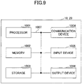
- FIG. 9 is a diagram illustrating an example of a hardware configuration of the terminal 20 and the base station 10 according to the embodiment.
- Each of the above-described terminal 20 and the base station 10 may be physically configured as a computer device including a processor 1001, a memory 1002, a storage device 1003, a communication device 1004, an input device 1005, an output device 1006, a bus 1007, or the like.
- the term “device” can be replaced with a circuit, a device, a unit, or the like.
- the hardware configuration of the terminal 20 and the base station 10 may be configured to include one or more of the devices depicted in the figures, which are indicated by 1001 through 1006, or may be configured without some devices.
- Each function of the terminal 20 and the base station 10 is implemented by loading predetermined software (program) on hardware, such as the processor 1001 and the memory 1002, so that the processor 1001 performs computation and controls communication by the communication device 1004, and at least one of reading and writing of data in the memory 1002 and the storage device 1003.
- predetermined software program
- the processor 1001 for example, operates an operating system to control the entire computer.
- the processor 1001 may be configured with a central processing unit (CPU: Central Processing Unit) including an interface with a peripheral device, a control device, a processing device, a register, or the like.
- CPU Central Processing Unit
- the processor 1001 reads a program (program code), a software module, data, or the like from at least one of the storage 1003 and the communication device 1004 to the memory 1002, and executes various processes according to these.
- a program is used which causes a computer to execute at least a part of the operations described in the above-described embodiment.
- the control unit 203 of the terminal 20 may be implemented by a control program that is stored in the memory 1002 and that is operated by the processor 1001. While the various processes described above are described as being executed in one processor 1001, they may be executed simultaneously or sequentially by two or more processors 1001.
- the processor 1001 may be implemented by one or more chips.
- the program may be transmitted from a network via a telecommunications line.
- the memory 1002 is a computer readable storage medium, and, for example, the memory 1002 may be formed of at least one of a Read Only Memory (ROM), an Erasable Programmable ROM (EPROM), an Electrically Erasable Programmable ROM (EEPROM), and a Random Access Memory (RAM).
- ROM Read Only Memory
- EPROM Erasable Programmable ROM
- EEPROM Electrically Erasable Programmable ROM
- RAM Random Access Memory
- the memory 1002 may be referred to as a register, a cache, a main memory (main storage device), or the like.
- the memory 1002 may store a program (program code), a software module, or th like, which can be executed for implementing the radio communication method according to the embodiments of the present disclosure.
- the storage 1003 is a computer readable storage medium and may be formed of, for example, at least one of an optical disk, such as a Compact Disc ROM (CD-ROM), a hard disk drive, a flexible disk, an optical magnetic disk (e.g., a compact disk, a digital versatile disk, a Blu-ray (registered trademark) disk), a smart card, a flash memory (e.g., a card, a stick, a key drive), a floppy (registered trademark) disk, or a magnetic strip.
- the storage 1003 may be referred to as an auxiliary storage device.
- the above-described storage medium may be, for example, a database including at least one of the memory 1002 and the storage 1003, a server, or any other suitable medium.
- the communication device 1004 is hardware (transmitting and receiving device) for performing communication between computers through at least one of a wired network and a wireless network, and is also referred to, for example, as a network device, a network controller, a network card, a communication module, or the like.
- the communication device 1004 may be configured to include, for example, a high frequency switch, a duplexer, a filter, a frequency synthesizer, or the like to implement at least one of frequency division duplex (FDD: Frequency Division Duplex) and time division duplex (TDD: Time Division Duplex).
- FDD Frequency Division Duplex
- TDD Time Division Duplex
- the input device 1005 is an input device (e.g., a keyboard, mouse, microphone, switch, button, or sensor) that receives an external input.
- the output device 1006 is an output device (e.g., a display, speaker, or LED lamp) that implements an external output.
- the input device 1005 and the output device 1006 may have an integrated configuration (for example, a touch panel).
- Each device such as the processor 1001 and the memory 1002, is also connected by the bus 1007 for communicating information.
- the bus 1007 may be formed of a single bus or may be formed of different buses between devices.
- the terminal 20 and the base station 10 may each include hardware, such as a microprocessor, a digital signal processor (DSP: Digital Signal Processor), an Application Specific Integrated Circuit (ASIC), a Programmable Logic Device (PLD), and a Field Programmable Gate Array (FPGA), which may implement some or all of the functional blocks.
- DSP Digital Signal Processor
- ASIC Application Specific Integrated Circuit
- PLD Programmable Logic Device
- FPGA Field Programmable Gate Array
- processor 1001 may be implemented using at least one of these hardware components.
- a terminal including a transmitting unit that transmits, on a sidelink resource, at least one of a transport block or control information; and a control unit that selects a specific operation related to feedback, to a base station, of Hybrid Automatic Repeat Request-Acknowledgement (HARQ-ACK) for the sidelink resource, in response to detecting that feedback for the at least one of the transport block or the control information is not performed.
- HARQ-ACK Hybrid Automatic Repeat Request-Acknowledgement
- the control unit may select to transmit a positive acknowledgement (ACK) to the base station, as the specific operation related to the feedback, to the base station, of the HARQ-ACK.
- ACK positive acknowledgement
- the control unit may select not to perform a feedback of a HARQ-ACK to the base station, as the specific operation related to the feedback, to the base station, of the HARQ-ACK.
- control unit may select, based on the configuration, not to perform the feedback of the HARQ-ACK for the sidelink resource to the base station, as the specific operation related to the feedback, to the base station, of the HARQ-ACK.
- control unit may determine the specific operation related to the feedback, to the base station, of the HARQ-ACK, in accordance with a condition under which the feedback is not performed.
- the transmitting terminal can request the base station for a resource for the retransmission.
- a communication method to be executed by a terminal including transmitting, on a sidelink resource, at least one of a transport block or control information; and selecting a specific operation related to feedback, to a base station, of Hybrid Automatic Repeat Request-Acknowledgement (HARQ-ACK) for the sidelink resource, in response to detecting that feedback for the at least one of the transport block or the control information is not performed.
- HARQ-ACK Hybrid Automatic Repeat Request-Acknowledgement
- An operation by a plurality of functional units may be physically performed by one component or an operation by one functional unit may be physically executed by a plurality of components.
- the order of processing may be changed as long as there is no contradiction.
- the terminal 20 and the base station 10 are described using functional block diagrams, but such devices may be implemented in hardware, software, or a combination thereof.
- Software operated by a processor included in the terminal 20 in accordance with the embodiments of the present invention and software operated by a processor included in the base station 10 in accordance with the embodiments of the present invention may be stored in a random access memory (RAM), a flash memory, a read-only memory (ROM), an EPROM, an EEPROM, a register, a hard disk (HDD), a removable disk, a CD-ROM, a database, a server, or any other suitable storage medium.
- RAM random access memory
- ROM read-only memory
- EPROM an EPROM
- EEPROM electrically erasable programmable read-only memory
- register a register
- HDD hard disk
- CD-ROM compact disc-read only memory
- database a database
- server or any other suitable storage medium.
- Notification of information is not limited to the aspects/embodiments described in the disclosure, and notification of information may be made by another method.
- notification of information may be implemented by physical layer signaling (e.g., Downlink Control Information (DCI), Uplink Control Information (UCI), higher layer signaling (e.g., Radio Resource Control (RRC) signaling, Medium Access Control (MAC) signaling, broadcast information (Master Information Block (MIB), System Information Block (SIB))), or other signals or combinations thereof.
- DCI Downlink Control Information
- UCI Uplink Control Information
- RRC Radio Resource Control
- MAC Medium Access Control
- MIB Master Information Block
- SIB System Information Block
- RRC signaling may be referred to as an RRC message, for example, which may be an RRC connection setup message, an RRC connection reconfiguration message, or the like.
- LTE Long Term Evolution
- LTE-A LTE-Advanced
- SUPER 3G IMT-Advanced
- 4G 4th generation mobile communication system
- 5G 5th generation mobile communication system
- Future Radio Access FAA
- W-CDMA Registered Trademark
- GSM Global System for Mobile Communications
- UMB Ultra Mobile Broadband
- IEEE 802.11 Wi-Fi (Registered Trademark)
- IEEE 802.16 WiMAX (Registered Trademark)
- IEEE 802.20 Ultra-WideBand (UWB), Bluetooth (Registered Trademark), any other appropriate system, and a next generation system extended based on theses.
- a plurality of systems may be combined (e.g., a combination of at least one of LTE and LTE-A and 5G) to be applied.
- the particular operation described in this disclosure to be performed by the base station 10 may be performed by an upper node in some cases. It is apparent that in a network consisting of one or more network nodes having the base station 10, various operations performed for communicating with the terminal may be performed by at least one of the base station 10 and a network node other than the base station 10 (e.g., MME or S-GW can be considered, however, the network node is not limited to these).
- a network node other than the base station 10 e.g., MME or S-GW can be considered, however, the network node is not limited to these.
- MME Mobility Management Entity
- Input and output information may be stored in a specific location (e.g., memory) or managed using management tables. Input and output information may be overwritten, updated, or added. Output information may be deleted. The input information may be transmitted to another device.
- the determination may be made by a value (0 or 1) represented by 1 bit, by a true or false value (Boolean: true or false), or by comparison of numerical values (e.g., a comparison with a predefined value).
- Notification of predetermined information is not limited to a method that is explicitly performed, and may also be made implicitly (e.g. "no notice of the predetermined information").
- Software should be broadly interpreted to mean, regardless of whether referred to as software, firmware, middleware, microcode, hardware description language, or any other name, instructions, sets of instructions, code, code segments, program code, programs, subprograms, software modules, applications, software applications, software packages, routines, subroutines, objects, executable files, executable threads, procedures, functions, or the like.
- Software, instructions, information, or the like may also be transmitted and received via a transmission medium.
- a transmission medium For example, when software is transmitted from a website, server, or other remote source using at least one of wireline technology (such as coaxial cable, fiber optic cable, twisted pair, digital subscriber line) and wireless technology (e.g., infrared or microwave), at least one of these wireline technology and wireless technology is included within the definition of a transmission medium.
- wireline technology such as coaxial cable, fiber optic cable, twisted pair, digital subscriber line
- wireless technology e.g., infrared or microwave
- the information, signals, or the like described in this disclosure may be represented using any of a variety of different techniques.
- data, instructions, commands, information, signals, bits, symbols, chips, or the like which may be referred to throughout the above description may be represented by voltages, currents, electromagnetic waves, magnetic fields or magnetic particles, optical fields or photons, or any combination thereof.
- At least one of the channels and the symbols may be a signal (signaling).
- the signal may also be a message.
- radio resources may be those indicated by an index.
- Base Station Radio Base Station
- NodeB NodeB
- eNodeB(eNB) gNodeB (gNB)
- Access Point "Transmission Point”
- Reception Point Transmission/Reception Point
- Cell Cell Group
- Carrier Carrier
- Component Carrier and the like
- the base stations may be referred to in terms such as macro-cell, small-cell, femto-cell, or pico-cell.
- the base station can accommodate one or more (e.g., three) cells. Where the base station accommodates a plurality of cells, the entire coverage area of the base station can be divided into a plurality of smaller areas, each smaller area can also provide communication services by means of a base station subsystem (e.g., an indoor small base station (RRH) or a remote Radio Head).
- a base station subsystem e.g., an indoor small base station (RRH) or a remote Radio Head.
- RRH indoor small base station
- a remote Radio Head e.g., a base station subsystem
- the term "cell” or “sector” refers to a portion or all of the coverage area of at least one of the base station and base station subsystem that provides communication services at the coverage.
- MS Mobile Station
- UE User Equipment
- the mobile station may be referred to by one of ordinary skill in the art as a subscriber station, a mobile unit, a subscriber unit, a wireless unit, a remote unit, a mobile device, a wireless device, a wireless communication device, a remote device, a mobile subscriber station, an access terminal, a mobile terminal, a wireless terminal, a remote terminal, a handset, a user agent, a mobile client, a client, or some other suitable term.
- At least one of a base station and a mobile station may be referred to as a transmitter, receiver, communication device, or the like.
- At least one of a base station and a mobile station may be a device installed in a mobile body, a mobile body itself, or the like.
- the mobile body may be a vehicle (e.g., a car or an airplane), an unmanned mobile (e.g., a drone or an automated vehicle), or a robot (manned or unmanned).
- At least one of a base station and a mobile station includes a device that does not necessarily move during communication operations.
- at least one of a base station and a mobile station may be an Internet of Things (IoT) device such as a sensor.
- IoT Internet of Things
- the base station in the present disclosure may be replaced with the user terminal.
- various aspects/embodiments of the present disclosure may be applied to a configuration in which communication between the base station and the user terminal is replaced with communication between multiple user terminals (e.g., may be referred to as Device-to-Device (D2D) or Vehicle-to-Everything (V2X)).
- D2D Device-to-Device
- V2X Vehicle-to-Everything
- a configuration may be such that the above-described function of the base station 10 is included in the user terminal 20.
- the terms “up” and “down” may also be replaced with the terms corresponding to terminal-to-terminal communication (e.g., "side”).
- an uplink channel, a downlink channel, or the like may be replaced with a sidelink channel.
- the user terminal according to the present disclosure may be replaced with a base station.
- a configuration may be such that, the function included in the above-described user terminal 20 may be included in the base station 10.
- connection means any direct or indirect connection or connection between two or more elements and may include the presence of one or more intermediate elements between two elements “connected” or “coupled” with each other.
- the coupling or connection between the elements may be physical, logical, or a combination of these.
- connection may be replaced with "access”.
- the two elements may be considered as being “connected” or “coupled” to each other using at least one of the one or more wires, cables, and printed electrical connections and, as a number of non-limiting and non-inclusive examples, electromagnetic energy having wavelengths in the radio frequency region, the microwave region, and the light (both visible and invisible) region.
- the reference signal may be abbreviated as RS (Reference Signal) or may be referred to as a pilot, depending on the standard applied.
- the expression “based on” does not mean “based on only” unless otherwise specified. In other words, the expression “based on” means both “based on only” and “at least based on.”
- a radio frame may be formed of one or more frames in the time domain.
- each of the one or more frames may be referred to as a subframe.
- a subframe may further be formed of one or more slots in the time domain.
- a subframe may be a fixed time length (e.g., 1 ms) that does not depend on numerology.
- the numerology may be a communication parameter to be applied to at least one of transmission or reception of a signal or a channel.
- the numerology may represent, for example, at least one of a subcarrier spacing (SCS: SubCarrier Spacing), a bandwidth, a symbol length, a cyclic prefix length, a transmission time interval (TTI: Transmission Time Interval), a symbol number per TTI, a radio frame configuration, a specific filtering process performed by a transceiver in a frequency domain, a specific windowing process performed by a transceiver in a time domain, or the like.
- SCS SubCarrier Spacing
- TTI Transmission Time Interval
- a slot may be formed of, in a time domain, one or more symbols (Orthogonal Frequency Division Multiplexing (OFDM) symbols, Single Carrier Frequency Division Multiple Access (SC-FDMA) symbols).
- OFDM Orthogonal Frequency Division Multiplexing
- SC-FDMA Single Carrier Frequency Division Multiple Access
- a slot may be a unit of time based on the numerology.
- a slot may include a plurality of mini-slots. In a time domain, each mini-slot may be formed of one or more symbols. A mini-slot may also be referred to as a sub-slot. A mini-slot may be formed of fewer symbols than those of a slot.
- the PDSCH (or PUSCH) transmitted in a unit of time that is greater than a mini-slot may be referred to as PDSCH (or PUSCH) mapping type A.
- the PDSCH (or PUSCH) transmitted using a mini-slot may be referred to as PDSCH (or PUSCH) mapping type B.
- Each of the radio frame, subframe, slot, mini-slot, and symbol represents a time unit for transmitting a signal.
- the radio frame, subframe, slot, mini-slot, and symbol may be called by respective different names.
- one subframe may be referred to as a transmission time interval (TTI: Transmission Time Interval)
- TTI Transmission Time Interval
- a plurality of consecutive subframes may be referred to as TTI
- one slot or one mini-slot may be referred to as TTI.
- at least one of a subframe and TTI may be a subframe (1 ms) in the existing LTE, may be a time interval shorter than 1 ms (e.g., 1 to 13 symbols), or a time interval longer than 1 ms.
- the unit representing the TTI may be referred to as a slot, a mini-slot, or the like, instead of a subframe.
- the TTI refers to, for example, the minimum time unit of scheduling in radio communication.
- the base station performs scheduling for allocating radio resources (such as a frequency bandwidth, or transmission power that can be used in each user terminal) in units of TTIs to each user terminal.
- radio resources such as a frequency bandwidth, or transmission power that can be used in each user terminal.
- the definition of the TTI is not limited to this.
- the TTI may be a transmission time unit, such as a channel coded data packet (transport block), a code block, and a codeword, or may be a processing unit for scheduling, link adaptation, or the like. Note that, when a TTI is provided, a time interval (e.g., a symbol number) onto which a transport block, a code block, or a code ward is actually mapped may be shorter than the TTI.
- a time interval e.g., a symbol number
- one or more TTIs may be the minimum time unit of scheduling. Additionally, the number of slots (the number of mini-slots) forming the minimum time unit of scheduling may be controlled.
- a TTI with a time length of 1 ms may be referred to as an ordinary TTI (TTI in LTE Rel. 8-12), a normal TTI, a long TTI, an ordinary subframe, a normal subframe, a long subframe, a slot, or the like.
- TTI that is shorter than a normal TTI may be referred to as a shortened TTI, a short TTI, a partial TTI (partial TTI or fractional TTI), a shortened subframe, a short subframe, a mini-slot, a sub-slot, a slot, or the like.
- a long TTI (e.g., a normal TTI, a subframe) may be replaced with a TTI with a time length exceeding 1 ms
- a short TTI (e.g., a shortened TTI) may be replaced with a TTI with a TTI length that is shorter than the TTI length of the long TTI and longer than or equal to 1 ms.
- a resource block is a resource allocation unit in the time domain and the frequency domain, and may include one or more consecutive subcarriers in the frequency domain.
- a number of subcarriers included in a RB may be the same irrespective of numerology, and may be 12, for example. The number of subcarriers included in a RB may be determined based on numerology.
- the resource block may include one or more symbols in the time domain, and may have a length of one slot, one mini-slot, one subframe, or one TTI. Each of one TTI and one subframe may be formed of one or more resource blocks.
- one or more RBs may be referred to as a physical resource block (PRB: Physical RB), a subcarrier group (SCG: Sub-Carrier Group), a resource element group (REG: Resource Element Group), a PRB pair, a RB pair, or the like.
- PRB Physical resource block
- SCG Sub-Carrier Group
- REG Resource Element Group
- a resource block may be formed of one or more resource elements (RE: Resource Element).
- RE Resource Element
- 1 RE may be a radio resource area of 1 subcarrier and 1 symbol.
- a bandwidth part (which may also be referred to as a partial bandwidth) may represent, in a certain carrier, a subset of consecutive common RB (common resource blocks) for a certain numerology.
- the common RB may be specified by an index of a RB when a common reference point of the carrier is used as a reference.
- a PRB may be defined in a BWP, and may be numbered in the BWP.
- the BWP may include a BWP for UL (UL BWP) and a BWP for DL (DL BWP).
- UL BWP UL BWP
- DL BWP DL BWP
- one or more BWPs may be configured within one carrier.
- At least one of the configured BWPs may be active, and the UE is may not assume that a predetermined signal/channel is communicated outside the active BWP. Note that "cell,” “carrier,” or the like in the present disclosure may be replaced with “BWP.”
- the structures of the above-described radio frame, subframe, slot, mini-slot, symbol, or the like are merely illustrative.
- the following configurations can be variously changed: the number of subframes included in the radio frame; the number of slots per subframe or radio frame; the number of mini-slots included in the slot; the number of symbols and RBs included in the slot or mini-slot; the number of subcarriers included in the RB; and the number of symbols, the symbol length, the cyclic prefix (CP: Cyclic Prefix) length, or the like, within the TTI.
- CP Cyclic Prefix
- a and B are different may imply that "A and B are different from each other.” Note that the term may also imply “each of A and B is different from C.”
- the terms, such as “separated” or “coupled,” may also be interpreted similarly.
Landscapes
- Engineering & Computer Science (AREA)
- Signal Processing (AREA)
- Computer Networks & Wireless Communication (AREA)
- Mobile Radio Communication Systems (AREA)
Applications Claiming Priority (1)
| Application Number | Priority Date | Filing Date | Title |
|---|---|---|---|
| PCT/JP2019/035987 WO2021048991A1 (fr) | 2019-09-12 | 2019-09-12 | Terminal et procédé de communication |
Publications (2)
| Publication Number | Publication Date |
|---|---|
| EP4030869A1 true EP4030869A1 (fr) | 2022-07-20 |
| EP4030869A4 EP4030869A4 (fr) | 2023-04-26 |
Family
ID=74866321
Family Applications (1)
| Application Number | Title | Priority Date | Filing Date |
|---|---|---|---|
| EP19945167.5A Pending EP4030869A4 (fr) | 2019-09-12 | 2019-09-12 | Terminal et procédé de communication |
Country Status (6)
| Country | Link |
|---|---|
| US (1) | US12557072B2 (fr) |
| EP (1) | EP4030869A4 (fr) |
| JP (1) | JP7469320B2 (fr) |
| CN (1) | CN114342554B (fr) |
| AU (1) | AU2019465791B2 (fr) |
| WO (1) | WO2021048991A1 (fr) |
Families Citing this family (5)
| Publication number | Priority date | Publication date | Assignee | Title |
|---|---|---|---|---|
| EP4091277A1 (fr) * | 2020-01-16 | 2022-11-23 | Lenovo (Singapore) Pte. Ltd. | Retransmission d'un bloc de transport ayant une rétroaction de liaison latérale désactivée |
| KR102840432B1 (ko) * | 2020-04-28 | 2025-07-29 | 삼성전자주식회사 | 무선 통신 시스템에서 단말의 송신 전력 제어 방법 및 장치 |
| KR20230035323A (ko) * | 2020-07-14 | 2023-03-13 | 퀄컴 인코포레이티드 | 릴레이에 의해 보조되는 네트워크 코딩을 사용한 차량-사물 통신들 |
| WO2022041183A1 (fr) * | 2020-08-31 | 2022-03-03 | Qualcomm Incorporated | Schéma d'indication pour transmissions de codes sans débit sans informations de rétroaction |
| US12302310B2 (en) * | 2021-07-14 | 2025-05-13 | Qualcomm Incorporated | Cancellation of different sidelink channels |
Family Cites Families (14)
| Publication number | Priority date | Publication date | Assignee | Title |
|---|---|---|---|---|
| JP4978327B2 (ja) * | 2007-06-19 | 2012-07-18 | 富士通株式会社 | 再送制御方法及びその装置 |
| CN101616492B (zh) * | 2008-06-26 | 2012-04-04 | 中兴通讯股份有限公司 | 上行应答消息反馈方法 |
| WO2010035496A1 (fr) * | 2008-09-29 | 2010-04-01 | パナソニック株式会社 | Dispositif de transmission radio et procédé de transmission radio |
| WO2011139058A2 (fr) * | 2010-05-04 | 2011-11-10 | Samsung Electronics Co., Ltd. | Procédé d'indication de commande dans des systèmes de communication à entrées multiples et à sorties multiples |
| JP2015139106A (ja) * | 2014-01-22 | 2015-07-30 | 株式会社Nttドコモ | ユーザ端末、無線基地局及び無線通信方法 |
| US10440771B2 (en) * | 2015-03-06 | 2019-10-08 | Qualcomm Incorporated | Conditional HARQ feedback |
| US10798697B2 (en) * | 2016-09-14 | 2020-10-06 | Sharp Kabushiki Kaisha | Terminal apparatus that transmit PUSCH, base station apparatus that receives PUSCH, and communication method that uses PUSCH |
| US10306652B2 (en) * | 2017-02-10 | 2019-05-28 | Qualcomm Incorporated | Feedback interference management in sidelink |
| CN108809525A (zh) * | 2017-05-04 | 2018-11-13 | 株式会社Ntt都科摩 | Harq-ack反馈方法、harq-ack提取方法、基站和用户设备 |
| WO2019021929A1 (fr) * | 2017-07-24 | 2019-01-31 | シャープ株式会社 | Dispositif terminal, dispositif station de base et procédé de communication |
| US11432369B2 (en) * | 2018-06-19 | 2022-08-30 | Apple Inc. | Reference signal and control information processing in 5G-NR wireless systems |
| US12082207B2 (en) * | 2018-09-27 | 2024-09-03 | Interdigital Patent Holdings, Inc. | Uu based sidelink control for Nr V2x |
| CN111431671B (zh) * | 2019-01-09 | 2022-04-12 | 大唐移动通信设备有限公司 | 一种终端节点间harq反馈配置的方法及设备 |
| US11589417B2 (en) * | 2019-07-17 | 2023-02-21 | Intel Corporation | Sidelink communication range signaling |
-
2019
- 2019-09-12 CN CN201980099933.1A patent/CN114342554B/zh active Active
- 2019-09-12 AU AU2019465791A patent/AU2019465791B2/en active Active
- 2019-09-12 JP JP2021545062A patent/JP7469320B2/ja active Active
- 2019-09-12 US US17/641,326 patent/US12557072B2/en active Active
- 2019-09-12 EP EP19945167.5A patent/EP4030869A4/fr active Pending
- 2019-09-12 WO PCT/JP2019/035987 patent/WO2021048991A1/fr not_active Ceased
Also Published As
| Publication number | Publication date |
|---|---|
| EP4030869A4 (fr) | 2023-04-26 |
| AU2019465791A1 (en) | 2022-03-03 |
| AU2019465791B2 (en) | 2025-10-23 |
| US12557072B2 (en) | 2026-02-17 |
| CN114342554B (zh) | 2024-10-18 |
| JP7469320B2 (ja) | 2024-04-16 |
| WO2021048991A1 (fr) | 2021-03-18 |
| CN114342554A (zh) | 2022-04-12 |
| US20220338172A1 (en) | 2022-10-20 |
| JPWO2021048991A1 (fr) | 2021-03-18 |
Similar Documents
| Publication | Publication Date | Title |
|---|---|---|
| EP3905768B1 (fr) | Terminal et procédé de communication | |
| US12395979B2 (en) | User equipment and communication apparatus | |
| US12126453B2 (en) | Terminal and communication method | |
| US12120683B2 (en) | User equipment and feedback information transmission method | |
| EP3979678A1 (fr) | Terminal et procédé de communication | |
| US12237925B2 (en) | Terminal and communication method | |
| US12557072B2 (en) | Terminal and communication method | |
| EP4030814B1 (fr) | Terminal | |
| US12250681B2 (en) | Terminal and communication method | |
| EP4037394A1 (fr) | Terminal et procédé de communication | |
| US20220377724A1 (en) | Terminal and communication method | |
| EP4102921A1 (fr) | Terminal, station de base et procédé de communication | |
| EP4102932B1 (fr) | Terminal et procédé de communication | |
| US20220256507A1 (en) | User equipment | |
| EP4102882A1 (fr) | Terminal et procédé de mesure | |
| EP4040899A1 (fr) | Terminal et procédé de communication | |
| EP4124170A1 (fr) | Terminal et procédé de communication | |
| EP4152801A1 (fr) | Terminal et procédé de communication | |
| EP4017187A1 (fr) | Terminal et procédé de communication |
Legal Events
| Date | Code | Title | Description |
|---|---|---|---|
| STAA | Information on the status of an ep patent application or granted ep patent |
Free format text: STATUS: THE INTERNATIONAL PUBLICATION HAS BEEN MADE |
|
| PUAI | Public reference made under article 153(3) epc to a published international application that has entered the european phase |
Free format text: ORIGINAL CODE: 0009012 |
|
| STAA | Information on the status of an ep patent application or granted ep patent |
Free format text: STATUS: REQUEST FOR EXAMINATION WAS MADE |
|
| 17P | Request for examination filed |
Effective date: 20220210 |
|
| AK | Designated contracting states |
Kind code of ref document: A1 Designated state(s): AL AT BE BG CH CY CZ DE DK EE ES FI FR GB GR HR HU IE IS IT LI LT LU LV MC MK MT NL NO PL PT RO RS SE SI SK SM TR |
|
| DAV | Request for validation of the european patent (deleted) | ||
| DAX | Request for extension of the european patent (deleted) | ||
| A4 | Supplementary search report drawn up and despatched |
Effective date: 20230324 |
|
| RIC1 | Information provided on ipc code assigned before grant |
Ipc: H04L 1/1829 20230101ALI20230320BHEP Ipc: H04W 28/04 20090101ALI20230320BHEP Ipc: H04W 4/40 20180101ALI20230320BHEP Ipc: H04W 92/18 20090101AFI20230320BHEP |
|
| P01 | Opt-out of the competence of the unified patent court (upc) registered |
Effective date: 20230509 |
|
| STAA | Information on the status of an ep patent application or granted ep patent |
Free format text: STATUS: EXAMINATION IS IN PROGRESS |
|
| 17Q | First examination report despatched |
Effective date: 20250220 |