EP4030965B1 - Improved support device for furniture shelves - Google Patents
Improved support device for furniture shelves Download PDFInfo
- Publication number
- EP4030965B1 EP4030965B1 EP20785602.2A EP20785602A EP4030965B1 EP 4030965 B1 EP4030965 B1 EP 4030965B1 EP 20785602 A EP20785602 A EP 20785602A EP 4030965 B1 EP4030965 B1 EP 4030965B1
- Authority
- EP
- European Patent Office
- Prior art keywords
- pin
- shelf
- supporting device
- slide
- previous
- Prior art date
- Legal status (The legal status is an assumption and is not a legal conclusion. Google has not performed a legal analysis and makes no representation as to the accuracy of the status listed.)
- Active
Links
Images




Classifications
-
- A—HUMAN NECESSITIES
- A47—FURNITURE; DOMESTIC ARTICLES OR APPLIANCES; COFFEE MILLS; SPICE MILLS; SUCTION CLEANERS IN GENERAL
- A47B—TABLES; DESKS; OFFICE FURNITURE; CABINETS; DRAWERS; GENERAL DETAILS OF FURNITURE
- A47B96/00—Details of cabinets, racks or shelf units not covered by a single one of groups A47B43/00 - A47B95/00; General details of furniture
- A47B96/06—Brackets or similar supporting means for cabinets, racks or shelves
- A47B96/066—Supporting means received within an edge of the shelf
-
- F—MECHANICAL ENGINEERING; LIGHTING; HEATING; WEAPONS; BLASTING
- F16—ENGINEERING ELEMENTS AND UNITS; GENERAL MEASURES FOR PRODUCING AND MAINTAINING EFFECTIVE FUNCTIONING OF MACHINES OR INSTALLATIONS; THERMAL INSULATION IN GENERAL
- F16B—DEVICES FOR FASTENING OR SECURING CONSTRUCTIONAL ELEMENTS OR MACHINE PARTS TOGETHER, e.g. NAILS, BOLTS, CIRCLIPS, CLAMPS, CLIPS OR WEDGES; JOINTS OR JOINTING
- F16B12/00—Jointing of furniture or the like, e.g. hidden from exterior
- F16B12/10—Jointing of furniture or the like, e.g. hidden from exterior using pegs, bolts, tenons, clamps, clips, or the like
- F16B12/12—Jointing of furniture or the like, e.g. hidden from exterior using pegs, bolts, tenons, clamps, clips, or the like for non-metal furniture parts, e.g. made of wood, of plastics
- F16B12/26—Jointing of furniture or the like, e.g. hidden from exterior using pegs, bolts, tenons, clamps, clips, or the like for non-metal furniture parts, e.g. made of wood, of plastics using snap-action elements
-
- F—MECHANICAL ENGINEERING; LIGHTING; HEATING; WEAPONS; BLASTING
- F16—ENGINEERING ELEMENTS AND UNITS; GENERAL MEASURES FOR PRODUCING AND MAINTAINING EFFECTIVE FUNCTIONING OF MACHINES OR INSTALLATIONS; THERMAL INSULATION IN GENERAL
- F16B—DEVICES FOR FASTENING OR SECURING CONSTRUCTIONAL ELEMENTS OR MACHINE PARTS TOGETHER, e.g. NAILS, BOLTS, CIRCLIPS, CLAMPS, CLIPS OR WEDGES; JOINTS OR JOINTING
- F16B12/00—Jointing of furniture or the like, e.g. hidden from exterior
- F16B12/10—Jointing of furniture or the like, e.g. hidden from exterior using pegs, bolts, tenons, clamps, clips, or the like
- F16B12/12—Jointing of furniture or the like, e.g. hidden from exterior using pegs, bolts, tenons, clamps, clips, or the like for non-metal furniture parts, e.g. made of wood, of plastics
- F16B12/24—Jointing of furniture or the like, e.g. hidden from exterior using pegs, bolts, tenons, clamps, clips, or the like for non-metal furniture parts, e.g. made of wood, of plastics using separate pins, dowels, or the like
Definitions
- the present invention relates to a perfected supporting device for furniture shelves for the reversible connection of a shelf to opposite shoulders of a piece of furniture.
- the device according to the present invention responds to the need, felt in the field, for being able to provide furniture shelves with increasingly miniaturized supporting devices which form a connection with the shoulders of a piece of furniture, so as to minimize the aesthetic impact and even completely disappear from sight when the shelf is assembled.
- Devices of this type are commonly called shelf brackets in the field, and have the function of stably, but removably, supporting and fixing a horizontal element (shelf) of a piece of furniture between two vertical elements commonly called shoulders.
- Said shelves and said shoulders are arranged perpendicular to each other.
- shelf brackets of this type are known in the state of the art, such shelf bracket is disclosed in GB 2 494 462 A or in particular the same Applicant is the holder of Italian patent application Nr. 102019000013428 which illustrates an innovative shelf-supporting device of which the present invention represents an improvement.
- this previous patent application in the name of the same applicant illustrates various alternative embodiments of a shelf-supporting device which has a minimal aesthetic impact once assembled in the shelf and allows an easy and rapid assembly and disassembly of the shelf itself with respect to the shoulders of the furniture.
- the shelf bracket 10 allows the reversible connection of a shelf 100 to the shoulders 200 of a piece of furniture wherein the connection is effected by means of a pin or plug 11 which is part of said shelf-supporting device 10 which is inserted into said shelf 100 and is configured so as to cause said pin or plug 11 to protrude from the edge B of said shelf 100 to enable it to be inserted into a corresponding housing hole 201 formed on the shoulder 200 of the furniture.
- Said shelf-supporting device 10 comprises a main body 12 with respect to which movable engagement means 15 are slidingly associated, in turn associated with an engagement pin 11.
- the device 10 is configured so that it can be inserted within the thickness of a shelf 100 and comprises movable engagement means 15 which slide with respect to the main body 12 along a sliding direction Y between a first non-operating position wherein the engagement pin 11 does not protrude from the transverse edge B of the shelf 100, and a second operating position in which the engagement pin 11 protrudes outwardly from the shelf 100.
- the main body 12 has a box-like shape and is preferably produced by coupling two half-shells, as can be seen for example in Figure 4 .
- the shelf bracket 10 comprises actuation means 13 of the engagement means 15 which can be rotated around an axis X substantially orthogonal with respect to the sliding direction Y of said engagement means 15.
- the movable engagement means comprise a slide 15 with which the engagement pin or plug 11 is integrally associated, and are driven in translation by means of motion transmission means which allow the rotational movement around the axis X of actuation means moved by the operator by means of a maneuvering tool U, to be transformed into the translational movement along the direction Y of the slide 15, and therefore the pin 11.
- the various embodiments of the shelf-supporting device object of the previous patent applications cited above in the name of the same applicant are analogous in the fact that the movable sliding element 15 comprises the pin or plug 11 suitable for being inserted into the hole 201 formed in the shoulder 200 of the piece of furniture with which the shelf 100 must be associated.
- the pin or plug 11 is generally produced in one piece, by moulding, with the slide 15.
- the slide 15 and pin 11 can be moulded in materials such as zamak, aluminium or plastic, which makes the production of the shelf bracket easier and inexpensive but which has proved to have various drawbacks.
- the mechanical seal of the shelf bracket itself should be mentioned, and in particular of the pin, that cannot be produced in excessively small diameters, which would cause breakage of the device.
- the known solutions in which the slide and pin are produced in one piece, for example in zamak or in plastic require diameters of the pin not less than 4 ⁇ 5 mm, which entails the need for producing holes of congruent diameters in the shoulder 200 of the furniture.
- the diameter of the pin 11 cannot be less than 4 ⁇ 5 mm.
- a bush is inserted into the hole 201 formed in the shoulder 200 of the piece of furniture as this expedient allows not only the aesthetics of the hole to be improved, as it hides the interior of the panel (generally made of chipboard) from the user's view, but also improves the mechanical seal of the shelf bracket as it limits the clearance between the pin 11 and the internal walls of the hole ensuring that the pin itself is aligned with the hole, limiting and guaranteeing greater uniformity of distribution of the shear stress acting on the pin itself.
- the undertaking of the present invention is to solve the drawbacks affecting supporting devices for shelves, also called shelf-bracket devices, of the type known in the state of the art.
- the objective of the present invention is to provide a supporting and fixing device for furniture shelves (shelf bracket), which further improves the reduced aesthetic impact of the shelf brackets known from the above-mentioned patent applications in the name of the same applicant, and which allows excellent mechanical resistance while requiring the creation of holes in the shoulder having very small diameters with respect to the diameters used in shelf brackets of the known type, generally not less than 4 ⁇ 5 mm, thus minimizing the aesthetic impact of the hole 201 formed on the shoulder of the furniture.
- An objective of the present invention is also to provide a shelf-supporting device that is more versatile so that it can be used with numerous different diameters of holes provided in the shoulders of the piece of furniture, creating in fact a modular system.
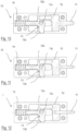
- FIGS. 1A-4 disclose embodiments not according to the invention, an example of a shelf-supporting device 10 is illustrated, for the reversible connection of a shelf 100 to opposite shoulders 200 of a piece of furniture, according to what is known from the above-mentioned patent applications in the name of the same applicant.
- the supporting device 10 is of the type suitable for creating a connection by means of a pin 11 associated with the shelf 100 and configured for protruding from the transverse edge B of said shelf 100 and suitable for being inserted into a corresponding housing hole 201 formed on the shoulder 200 of a piece of furniture.
- the shelf-supporting device 10 comprises a main body 12 with which movable engagement means 15 are slidingly associated, which is produced in a single piece with the pin 11.
- the device 10 is configured for being inserted within the thickness of a shelf 100 and said movable engagement means 15 are sliding with respect to the main body 12 along a sliding direction Y between a first non-operating position in which the pin 11 does not protrude from the transverse edge B of the shelf 100, and a second operating position in which the pin 11 protrudes outwardly from the shelf 100.
- Said main body 12 is box-shaped and is advantageously produced by the coupling of two half-shells.
- the shelf-supporting device 10 comprises actuation means 13 of the engagement means 15 which can be rotated around an axis X substantially orthogonal with respect to the sliding direction Y of said engagement means 15, or, according to alternative embodiments, actuation means of the engagement means 15 movable in the direction X, and further comprises motion transmission means 13b, 15c, 15b suitable for transforming the rotation movement around the rotation axis X of the actuation means 13 into the translational movement along the sliding direction Y of said movable engagement means 15, or it comprises other means, for example the slide 15 can have a tilted plane, suitable for transforming the translation in the direction X of the actuation means into the translational movement along the sliding direction Y of the movable engagement means 15 .
- a helical spring 19 is advantageously provided between the slide 15 and the body 12 in order to push the same slide forwards.
- the movable engagement means 15 comprise a slide 15 which is produced integrally with the pin 11.
- the slide 15 advantageously comprises an outlet 15a configured for receiving a cam 13 which comprises a substantially hollow cylindrical central body whose central hole 13c is shaped for receiving a maneuvering tool.
- the central body can be advantageously shaped so as to have a hole having two different diameters accessible with maneuvering tools having different dimensions.
- Said shelf-supporting device provides that the slide 15 and the pin 11 are produced integrally, so as to be able to reduce the production costs as the slide assembly with the pin can be produced directly by moulding using low-cost materials such as zamak, aluminium, plastic. With these materials, however, it is not possible to produce a device with a diameter of the pin 11 which is less than 4 ⁇ 5 mm, as a pin with a smaller diameter made of these materials could break during normal use.
- Figures 10 and 11 illustrate a shelf-supporting device 10 of a known type in which the slide 15 and the pin 11 are produced in a single piece.
- figure 10 shows a pin whose diameter is about 4 ⁇ 5 mm and is accepted by the market as it ensures the necessary mechanical resistance
- figure 11 shows a device whose pin, produced integrally with the slide, has a reduced diameter, i.e. about 2 ⁇ 3 mm. If the slide and the pin were produced in a single piece in materials such as zamak, aluminium or plastic, this device would not have the necessary mechanical strength and would break during use.
- Figure 12 shows a first embodiment of a shelf-supporting device 1 according to the present invention wherein the slide 15' and the pin 11 consist of two distinct elements advantageously joined together through a coupling with interference, i.e. interlocking.
- the slide and pin are distinct elements allows the two elements to be produced in different materials.
- the slide 15' can still be made of plastic, zamak or aluminium
- the pin 11 which in normal use is destined to be subjected to even very high stress, can be made of a material having higher mechanical characteristics, such as steel.
- this is an exploded view of the device 1 of figure 11 .
- the shelf-supporting device 1 for the reversible connection of a shelf to the shoulders of a piece of furniture provides that the connection be effected by means of a pin 11, 11', 11" associated with said shelf 100 and configured so as to protrude from the edge B of said shelf and be inserted into a corresponding housing hole 201 formed on the shoulder 200 of a piece of furniture.
- the shelf-supporting device 1 comprises a main body 12 with which movable engagement means 15', 15" are slidingly associated, advantageously consisting of a slide, associated with a pin 11, 11', 11".
- the shelf-supporting device 1 is configured for being inserted within the thickness of said shelf 100, and the movable engagement means 15', 15" slide with respect to the main body 12 of the device along a sliding direction Y between a first non-operating position wherein said pin 11, 11', 11" does not protrude from the shelf 100, and a second operating position wherein said pin 11, 11', 11" protrudes outwardly from the shelf 100 so as to be able to be inserted into a housing hole 201 formed on a shoulder 200 of a piece of furniture.
- the shelf-supporting device 1 comprises actuation means 13, in the embodiment shown in the figures, consisting of a cam, suitable for actuating the movable engagement means 15', 15", and motion transmission means 13b, 15c, 15b suitable for transforming the movement of said actuation means 13 into a translational movement along the sliding direction Y of the movable engagement means 15', 15".
- the shelf-supporting device 1 advantageously further comprises retaining means 15d suitable for keeping the engagement means 15', 15" blocked in said first non-operating position wherein said pin 11, 11', 11" does not protrude from said shelf 100, and furthermore the movable engagement means 15', 15" can be advantageously moved at least in a further third intermediate non-operating and non-blocked position wherein said pin 11, 11', 11" is free to move back until it is completely retracted but wherein said retaining means 15d do not keep said engagement means 15 blocked.
- the functionalities of the device 1 are therefore the same as those already described in the previous patent applications cited above, whose contents are referred to herein for reference, whereas the shelf-supporting device 1 according to the present invention is characterized in that the movable engagement means 15', 15" and the pin 11, 11', 11" are produced in two distinct parts, which are coupled together.
- the movable engagement means comprise a slide 15' with which said pin 11 is associated by means of an interference coupling.
- the slide 15' advantageously comprises a seat 20 for housing the pin 11 configured for receiving a first end 11a of said pin 11 with an interference coupling, i.e. by interlocking.
- said interference means can comprise a plurality of radial projections 11c which extend longitudinally for a portion of said first end 11a of said pin 11 destined for being inserted within the housing seat 20.
- the shelf-supporting device 1' is characterized in that the pin 11', 11" is associated with the movable engagement means, which in the example comprise a slide 15", by means of a shape coupling.
- the slide 15' comprises a housing seat 30 for housing the pin 11', 11" which is configured for receiving a first end 11a', 11a" of said pin 11', 11" in shape coupling.
- Said first end 11a', 11a" of said pin 11', 11" advantageously comprises a cylindrical portion 41 provided with a collar 41a, and said housing seat 30 of said slide 15" in turn comprises a groove 31 suitable for receiving said collar 41a, thus creating a shape coupling between the slide 15" and the pin 11', 11" suitable for inhibiting the possibility of longitudinal movements of the pin 11', 11" with respect to the slide 15".
- the shelf-supporting device 1' can provide that the pin 11', 11" be inserted in a bush 40', 40" configured for being inserted into a corresponding seat 12' formed within said main body 12, in particular a half-seat 12a', 12b' of said seat 12' being formed on each of the two half-shells 12a and 12b of the main body 12.
- a plurality of bushes 40', 40" can be advantageously arranged so that each bush has the same external diameter and the same external conformation so that it can be received within the cylindrical seat 12' formed on said main body 12, but different internal diameters, so that a pin with a different diameter can be inserted in each bush.
- a pin 11' having a larger diameter is inserted into a first bush 40', whereas a pin 11" having a larger diameter is inserted into a second bush 40'' having the same external diameter and the same external shape as the first bush 40'.
- the shelf bracket 1' is modular with respect to the possibility of associating pins 11', 11" having different diameters with the same device, and in particular with the same slide 15" and with the same main body 12.
- a pin 11, 11' having a reduced diameter of even less than 3 mm, the minimum diameter is deemed to be 2 mm, is in the embodiment with interference coupling of figures 12 and 13 , it is preferably made of steel for reasons of sealing, whereas the slide 15', 15" can be made for example of plastic, pins having larger diameters, for example a pin with a diameter of 5 mm, can be made of plastic without risks for the mechanical seal.
- the shelf-supporting device 1' according to the embodiment shown in figures 14, 15 and 16 therefore allows, thanks to the bushes having a different internal diameter, pins 11" made of steel having a small diameter or pins having a larger diameter that can be made either of steel or, for example, of plastic or other similar materials, to be indifferently housed.
- the shelf-supporting device 1, 1' in all its possible embodiments of which only some examples have been shown herein, can be further improved by providing that the pin 11, 11', 11" has its own free end 11b, 11b', 11b" suitable for being inserted into the hole 201 formed on the shoulder 200 of the piece of furniture, having a conical shape, as shown schematically in figure 17 and in figures 19A and 19B .
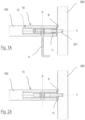
- the conical shape simplifies the operations for inserting the pin 11, 11', 11" into the hole 201 and, as can be seen in particular from the comparison between figures 18A and 18B and figures 19A and 19B , the conical shape also allows the clearance between the pin and the housing hole in the shoulder to be reduced if not cancelled, improving the stability of the coupling of the shelf to the shoulder of the furniture and reducing if not eliminating the possibility of the pin, also due to a greater lever arm, being subjected to bending stress that could compromise its mechanical resistance.
Landscapes
- Engineering & Computer Science (AREA)
- General Engineering & Computer Science (AREA)
- Mechanical Engineering (AREA)
- Assembled Shelves (AREA)
- Furniture Connections (AREA)
- Warehouses Or Storage Devices (AREA)
Applications Claiming Priority (2)
| Application Number | Priority Date | Filing Date | Title |
|---|---|---|---|
| IT102019000016343A IT201900016343A1 (it) | 2019-09-16 | 2019-09-16 | Dispositivo di supporto perfezionato per ripiani di mobili |
| PCT/IB2020/058361 WO2021053463A1 (en) | 2019-09-16 | 2020-09-09 | Improved support device for furniture shelves |
Publications (2)
| Publication Number | Publication Date |
|---|---|
| EP4030965A1 EP4030965A1 (en) | 2022-07-27 |
| EP4030965B1 true EP4030965B1 (en) | 2024-03-20 |
Family
ID=69191143
Family Applications (1)
| Application Number | Title | Priority Date | Filing Date |
|---|---|---|---|
| EP20785602.2A Active EP4030965B1 (en) | 2019-09-16 | 2020-09-09 | Improved support device for furniture shelves |
Country Status (10)
| Country | Link |
|---|---|
| US (1) | US11877657B2 (pl) |
| EP (1) | EP4030965B1 (pl) |
| CN (1) | CN114391068B (pl) |
| BR (1) | BR112022004176A2 (pl) |
| CA (1) | CA3150319A1 (pl) |
| DK (1) | DK4030965T3 (pl) |
| ES (1) | ES2984218T3 (pl) |
| IT (1) | IT201900016343A1 (pl) |
| PL (1) | PL4030965T3 (pl) |
| WO (1) | WO2021053463A1 (pl) |
Families Citing this family (6)
| Publication number | Priority date | Publication date | Assignee | Title |
|---|---|---|---|---|
| DE212020000339U1 (de) * | 2019-07-31 | 2021-01-21 | Leonardo S.R.L. | Tragvorrichtung für Möbelfachböden |
| IT202000014326A1 (it) * | 2020-06-16 | 2021-12-16 | Effegi Brevetti Srl | Dispositivo di supporto e di fissaggio di ripiani di mobili |
| EP4236726B1 (en) * | 2020-11-02 | 2025-01-08 | Bauce Bruno & C. S.r.l. | Shelf system comprising a marble shelf |
| IT202000026440A1 (it) * | 2020-11-05 | 2022-05-05 | Leonardo Srl | Dispositivo di supporto per ripiani di mobili con trasferimento ottimizzato dei carichi |
| US12018707B2 (en) * | 2021-03-01 | 2024-06-25 | Välinge Innovation AB | Mechanical connection arrangement for panels |
| IT202100025988A1 (it) * | 2021-10-11 | 2023-04-11 | Effegi Brevetti Srl | Dispositivo di supporto e di fissaggio di ripiani di mobili |
Family Cites Families (22)
| Publication number | Priority date | Publication date | Assignee | Title |
|---|---|---|---|---|
| DE4437273C2 (de) * | 1994-10-18 | 1996-09-26 | Salice Arturo Spa | Verbindungsbeschlag |
| ITPN20010004U1 (it) * | 2001-02-05 | 2002-08-05 | Livenza Ferramenta Srl | Supporto per ripiani ad inserimento rapido per mobili e simili |
| EP1454565A1 (en) * | 2003-02-12 | 2004-09-08 | Agostino Ferrari S.p.A. | A disappearing device for shelf support in furniture |
| DE102009060456A1 (de) * | 2009-10-19 | 2011-04-21 | Apple Inc., Cupertino | Verbindungsmittel für Bauelemente und Möbel |
| DE102010051372B4 (de) * | 2010-11-13 | 2012-05-24 | Amer Khodabandeh | Verbindungselement mit integrierter Schnappverbindung |
| IT1403925B1 (it) * | 2011-02-09 | 2013-11-08 | O M M S A S Dell Ing Roberto Mariani & C | Dispositivo di giunzione di pannelli di un mobile. |
| GB2494462B (en) * | 2011-09-12 | 2014-09-10 | Christopher Mark Wilkinson | Invisible support structure |
| ITPN20110085A1 (it) * | 2011-12-30 | 2013-07-01 | Livenza Ferramenta Srl | Reggi piano a scomparsa |
| ITMI20130076A1 (it) * | 2013-01-22 | 2014-07-23 | Agostino Ferrari Spa | Dispositivo reggipiano a scomparsa per supportare un ripiano di un mobile e ripiano di mobile comprendente tale dispositivo |
| PL3131438T3 (pl) * | 2014-04-14 | 2020-03-31 | Effegi Brevetti S.R.L. | Urządzenie do montażu/łączenia części mebli modułowych i akcesoriów meblowych |
| KR102485249B1 (ko) * | 2014-10-07 | 2023-01-04 | 에페기 브레베티 에스.알.엘. | 가구 및 가구용 액세서리의 부품들을 결합하기 위한 장치 |
| RU2683192C1 (ru) * | 2015-06-08 | 2019-03-26 | Кар С.Р.Л. | Соединительное устройство для компонентов предмета мебели |
| WO2017001419A1 (en) * | 2015-06-29 | 2017-01-05 | Ferramenta Livenza - Societa' A Responsabilita' Limitata | Joining device, particularly for joining a shelf to a wall of a piece of furniture |
| ITUB20151914A1 (it) * | 2015-07-07 | 2017-01-07 | Leonardo Srl | Dispositivo di giunzione a minima visibilita’ per parti di mobili e articoli da arredamento |
| ITUA20162145A1 (it) * | 2016-03-31 | 2017-10-01 | Effegi Brevetti Srl | Dispositivo di giunzione perfezionato per parti di mobili e complementi di arredo |
| SI3545202T1 (sl) * | 2016-11-24 | 2020-11-30 | Haefele Berlin Gmbh & Co Kg | Izboljšana naprava za povezovanje delov pohištva in pohištvenih dodatkov |
| IT201800002497A1 (it) * | 2018-02-08 | 2019-08-08 | O M M S R L Dell’Ing Roberto Natale Mariani | Giunzione ad espansione autobloccante per un mobile |
| CN109008350A (zh) * | 2018-09-05 | 2018-12-18 | 杭州顾家定制家居有限公司 | 一种橱柜滑销式层板托 |
| CA3113093A1 (en) * | 2018-10-26 | 2020-04-30 | Leonardo S.R.L. | Improved actuation and blocking system of a joint between a shoulder and a shelf of a piece of furniture or other furnishing items |
| DE212020000339U1 (de) * | 2019-07-31 | 2021-01-21 | Leonardo S.R.L. | Tragvorrichtung für Möbelfachböden |
| IT202000005086A1 (it) * | 2020-03-10 | 2021-09-10 | Effegi Brevetti Srl | Dispositivo di giunzione perfezionato per parti di mobili e complementi di arredo |
| IT202000014326A1 (it) * | 2020-06-16 | 2021-12-16 | Effegi Brevetti Srl | Dispositivo di supporto e di fissaggio di ripiani di mobili |
-
2019
- 2019-09-16 IT IT102019000016343A patent/IT201900016343A1/it unknown
-
2020
- 2020-09-09 WO PCT/IB2020/058361 patent/WO2021053463A1/en not_active Ceased
- 2020-09-09 PL PL20785602.2T patent/PL4030965T3/pl unknown
- 2020-09-09 BR BR112022004176A patent/BR112022004176A2/pt active IP Right Grant
- 2020-09-09 US US17/640,818 patent/US11877657B2/en active Active
- 2020-09-09 DK DK20785602.2T patent/DK4030965T3/da active
- 2020-09-09 EP EP20785602.2A patent/EP4030965B1/en active Active
- 2020-09-09 ES ES20785602T patent/ES2984218T3/es active Active
- 2020-09-09 CN CN202080061432.7A patent/CN114391068B/zh active Active
- 2020-09-09 CA CA3150319A patent/CA3150319A1/en active Pending
Also Published As
| Publication number | Publication date |
|---|---|
| CN114391068B (zh) | 2024-06-04 |
| US11877657B2 (en) | 2024-01-23 |
| US20220338630A1 (en) | 2022-10-27 |
| IT201900016343A1 (it) | 2021-03-16 |
| DK4030965T3 (da) | 2024-04-29 |
| PL4030965T3 (pl) | 2024-06-24 |
| ES2984218T3 (es) | 2024-10-29 |
| CN114391068A (zh) | 2022-04-22 |
| CA3150319A1 (en) | 2021-03-25 |
| EP4030965A1 (en) | 2022-07-27 |
| WO2021053463A1 (en) | 2021-03-25 |
| BR112022004176A2 (pt) | 2022-05-31 |
Similar Documents
| Publication | Publication Date | Title |
|---|---|---|
| EP4030965B1 (en) | Improved support device for furniture shelves | |
| US12239226B2 (en) | Device for supporting and fixing shelves of furniture | |
| CA2996745C (en) | Joining device with wide accessibility for parts of furniture and furnishing items | |
| EP4296525A2 (en) | Support device for furniture shelves | |
| US12571418B2 (en) | Actuation and blocking system of a joint between a shoulder and a shelf of furniture or other furnishing items | |
| CN106121427B (zh) | 具有缓冲器的家具铰链 | |
| CN106121428A (zh) | 具有缓冲器和弹簧的家具铰链 | |
| EP3482086B1 (en) | Joining system with front actuation axis for furniture | |
| CA3113093A1 (en) | Improved actuation and blocking system of a joint between a shoulder and a shelf of a piece of furniture or other furnishing items | |
| EP3919760B1 (en) | Joint for the firm interconnection of a first and a second panel of furniture and other furnishing items | |
| EP3815576A1 (en) | Supporting device for shelves | |
| EP3897292B1 (en) | Supporting and stable positioning system for a shelf of a piece of furniture | |
| RU2820810C2 (ru) | Опорное устройство полки для обратимого присоединения полки к торцам предмета мебели | |
| EP4247221B1 (en) | Rotating shelf-supporting device for removably supporting furniture shelves | |
| RU2800336C2 (ru) | Усовершенствованная система активации и блокировки узла крепления между боковиной и полкой детали мебели или другими элементами мебели | |
| US20200392754A1 (en) | Manual control device of the opening and closing of the lock of a door or window | |
| EP3075931B1 (en) | Hinge device |
Legal Events
| Date | Code | Title | Description |
|---|---|---|---|
| STAA | Information on the status of an ep patent application or granted ep patent |
Free format text: STATUS: UNKNOWN |
|
| STAA | Information on the status of an ep patent application or granted ep patent |
Free format text: STATUS: THE INTERNATIONAL PUBLICATION HAS BEEN MADE |
|
| PUAI | Public reference made under article 153(3) epc to a published international application that has entered the european phase |
Free format text: ORIGINAL CODE: 0009012 |
|
| STAA | Information on the status of an ep patent application or granted ep patent |
Free format text: STATUS: REQUEST FOR EXAMINATION WAS MADE |
|
| 17P | Request for examination filed |
Effective date: 20220203 |
|
| AK | Designated contracting states |
Kind code of ref document: A1 Designated state(s): AL AT BE BG CH CY CZ DE DK EE ES FI FR GB GR HR HU IE IS IT LI LT LU LV MC MK MT NL NO PL PT RO RS SE SI SK SM TR |
|
| DAV | Request for validation of the european patent (deleted) | ||
| DAX | Request for extension of the european patent (deleted) | ||
| STAA | Information on the status of an ep patent application or granted ep patent |
Free format text: STATUS: EXAMINATION IS IN PROGRESS |
|
| 17Q | First examination report despatched |
Effective date: 20230406 |
|
| GRAP | Despatch of communication of intention to grant a patent |
Free format text: ORIGINAL CODE: EPIDOSNIGR1 |
|
| STAA | Information on the status of an ep patent application or granted ep patent |
Free format text: STATUS: GRANT OF PATENT IS INTENDED |
|
| INTG | Intention to grant announced |
Effective date: 20231019 |
|
| GRAS | Grant fee paid |
Free format text: ORIGINAL CODE: EPIDOSNIGR3 |
|
| GRAA | (expected) grant |
Free format text: ORIGINAL CODE: 0009210 |
|
| STAA | Information on the status of an ep patent application or granted ep patent |
Free format text: STATUS: THE PATENT HAS BEEN GRANTED |
|
| P01 | Opt-out of the competence of the unified patent court (upc) registered |
Effective date: 20240125 |
|
| AK | Designated contracting states |
Kind code of ref document: B1 Designated state(s): AL AT BE BG CH CY CZ DE DK EE ES FI FR GB GR HR HU IE IS IT LI LT LU LV MC MK MT NL NO PL PT RO RS SE SI SK SM TR |
|
| REG | Reference to a national code |
Ref country code: GB Ref legal event code: FG4D |
|
| REG | Reference to a national code |
Ref country code: CH Ref legal event code: EP |
|
| REG | Reference to a national code |
Ref country code: IE Ref legal event code: FG4D |
|
| REG | Reference to a national code |
Ref country code: DE Ref legal event code: R096 Ref document number: 602020027592 Country of ref document: DE |
|
| REG | Reference to a national code |
Ref country code: DK Ref legal event code: T3 Effective date: 20240424 |
|
| PG25 | Lapsed in a contracting state [announced via postgrant information from national office to epo] |
Ref country code: LT Free format text: LAPSE BECAUSE OF FAILURE TO SUBMIT A TRANSLATION OF THE DESCRIPTION OR TO PAY THE FEE WITHIN THE PRESCRIBED TIME-LIMIT Effective date: 20240320 |
|
| REG | Reference to a national code |
Ref country code: LT Ref legal event code: MG9D |
|
| PG25 | Lapsed in a contracting state [announced via postgrant information from national office to epo] |
Ref country code: GR Free format text: LAPSE BECAUSE OF FAILURE TO SUBMIT A TRANSLATION OF THE DESCRIPTION OR TO PAY THE FEE WITHIN THE PRESCRIBED TIME-LIMIT Effective date: 20240621 |
|
| PG25 | Lapsed in a contracting state [announced via postgrant information from national office to epo] |
Ref country code: HR Free format text: LAPSE BECAUSE OF FAILURE TO SUBMIT A TRANSLATION OF THE DESCRIPTION OR TO PAY THE FEE WITHIN THE PRESCRIBED TIME-LIMIT Effective date: 20240320 Ref country code: RS Free format text: LAPSE BECAUSE OF FAILURE TO SUBMIT A TRANSLATION OF THE DESCRIPTION OR TO PAY THE FEE WITHIN THE PRESCRIBED TIME-LIMIT Effective date: 20240620 |
|
| REG | Reference to a national code |
Ref country code: NL Ref legal event code: MP Effective date: 20240320 |
|
| PG25 | Lapsed in a contracting state [announced via postgrant information from national office to epo] |
Ref country code: RS Free format text: LAPSE BECAUSE OF FAILURE TO SUBMIT A TRANSLATION OF THE DESCRIPTION OR TO PAY THE FEE WITHIN THE PRESCRIBED TIME-LIMIT Effective date: 20240620 Ref country code: NO Free format text: LAPSE BECAUSE OF FAILURE TO SUBMIT A TRANSLATION OF THE DESCRIPTION OR TO PAY THE FEE WITHIN THE PRESCRIBED TIME-LIMIT Effective date: 20240620 Ref country code: LT Free format text: LAPSE BECAUSE OF FAILURE TO SUBMIT A TRANSLATION OF THE DESCRIPTION OR TO PAY THE FEE WITHIN THE PRESCRIBED TIME-LIMIT Effective date: 20240320 Ref country code: HR Free format text: LAPSE BECAUSE OF FAILURE TO SUBMIT A TRANSLATION OF THE DESCRIPTION OR TO PAY THE FEE WITHIN THE PRESCRIBED TIME-LIMIT Effective date: 20240320 Ref country code: GR Free format text: LAPSE BECAUSE OF FAILURE TO SUBMIT A TRANSLATION OF THE DESCRIPTION OR TO PAY THE FEE WITHIN THE PRESCRIBED TIME-LIMIT Effective date: 20240621 Ref country code: FI Free format text: LAPSE BECAUSE OF FAILURE TO SUBMIT A TRANSLATION OF THE DESCRIPTION OR TO PAY THE FEE WITHIN THE PRESCRIBED TIME-LIMIT Effective date: 20240320 Ref country code: BG Free format text: LAPSE BECAUSE OF FAILURE TO SUBMIT A TRANSLATION OF THE DESCRIPTION OR TO PAY THE FEE WITHIN THE PRESCRIBED TIME-LIMIT Effective date: 20240320 |
|
| REG | Reference to a national code |
Ref country code: AT Ref legal event code: UEP Ref document number: 1667026 Country of ref document: AT Kind code of ref document: T Effective date: 20240320 |
|
| PG25 | Lapsed in a contracting state [announced via postgrant information from national office to epo] |
Ref country code: SE Free format text: LAPSE BECAUSE OF FAILURE TO SUBMIT A TRANSLATION OF THE DESCRIPTION OR TO PAY THE FEE WITHIN THE PRESCRIBED TIME-LIMIT Effective date: 20240320 Ref country code: LV Free format text: LAPSE BECAUSE OF FAILURE TO SUBMIT A TRANSLATION OF THE DESCRIPTION OR TO PAY THE FEE WITHIN THE PRESCRIBED TIME-LIMIT Effective date: 20240320 |
|
| PG25 | Lapsed in a contracting state [announced via postgrant information from national office to epo] |
Ref country code: NL Free format text: LAPSE BECAUSE OF FAILURE TO SUBMIT A TRANSLATION OF THE DESCRIPTION OR TO PAY THE FEE WITHIN THE PRESCRIBED TIME-LIMIT Effective date: 20240320 |
|
| PG25 | Lapsed in a contracting state [announced via postgrant information from national office to epo] |
Ref country code: NL Free format text: LAPSE BECAUSE OF FAILURE TO SUBMIT A TRANSLATION OF THE DESCRIPTION OR TO PAY THE FEE WITHIN THE PRESCRIBED TIME-LIMIT Effective date: 20240320 |
|
| PG25 | Lapsed in a contracting state [announced via postgrant information from national office to epo] |
Ref country code: IS Free format text: LAPSE BECAUSE OF FAILURE TO SUBMIT A TRANSLATION OF THE DESCRIPTION OR TO PAY THE FEE WITHIN THE PRESCRIBED TIME-LIMIT Effective date: 20240720 |
|
| PG25 | Lapsed in a contracting state [announced via postgrant information from national office to epo] |
Ref country code: PT Free format text: LAPSE BECAUSE OF FAILURE TO SUBMIT A TRANSLATION OF THE DESCRIPTION OR TO PAY THE FEE WITHIN THE PRESCRIBED TIME-LIMIT Effective date: 20240722 Ref country code: SM Free format text: LAPSE BECAUSE OF FAILURE TO SUBMIT A TRANSLATION OF THE DESCRIPTION OR TO PAY THE FEE WITHIN THE PRESCRIBED TIME-LIMIT Effective date: 20240320 |
|
| PG25 | Lapsed in a contracting state [announced via postgrant information from national office to epo] |
Ref country code: EE Free format text: LAPSE BECAUSE OF FAILURE TO SUBMIT A TRANSLATION OF THE DESCRIPTION OR TO PAY THE FEE WITHIN THE PRESCRIBED TIME-LIMIT Effective date: 20240320 Ref country code: CZ Free format text: LAPSE BECAUSE OF FAILURE TO SUBMIT A TRANSLATION OF THE DESCRIPTION OR TO PAY THE FEE WITHIN THE PRESCRIBED TIME-LIMIT Effective date: 20240320 |
|
| PG25 | Lapsed in a contracting state [announced via postgrant information from national office to epo] |
Ref country code: SK Free format text: LAPSE BECAUSE OF FAILURE TO SUBMIT A TRANSLATION OF THE DESCRIPTION OR TO PAY THE FEE WITHIN THE PRESCRIBED TIME-LIMIT Effective date: 20240320 |
|
| REG | Reference to a national code |
Ref country code: ES Ref legal event code: FG2A Ref document number: 2984218 Country of ref document: ES Kind code of ref document: T3 Effective date: 20241029 |
|
| PG25 | Lapsed in a contracting state [announced via postgrant information from national office to epo] |
Ref country code: SM Free format text: LAPSE BECAUSE OF FAILURE TO SUBMIT A TRANSLATION OF THE DESCRIPTION OR TO PAY THE FEE WITHIN THE PRESCRIBED TIME-LIMIT Effective date: 20240320 Ref country code: SK Free format text: LAPSE BECAUSE OF FAILURE TO SUBMIT A TRANSLATION OF THE DESCRIPTION OR TO PAY THE FEE WITHIN THE PRESCRIBED TIME-LIMIT Effective date: 20240320 Ref country code: RO Free format text: LAPSE BECAUSE OF FAILURE TO SUBMIT A TRANSLATION OF THE DESCRIPTION OR TO PAY THE FEE WITHIN THE PRESCRIBED TIME-LIMIT Effective date: 20240320 Ref country code: PT Free format text: LAPSE BECAUSE OF FAILURE TO SUBMIT A TRANSLATION OF THE DESCRIPTION OR TO PAY THE FEE WITHIN THE PRESCRIBED TIME-LIMIT Effective date: 20240722 Ref country code: IS Free format text: LAPSE BECAUSE OF FAILURE TO SUBMIT A TRANSLATION OF THE DESCRIPTION OR TO PAY THE FEE WITHIN THE PRESCRIBED TIME-LIMIT Effective date: 20240720 Ref country code: EE Free format text: LAPSE BECAUSE OF FAILURE TO SUBMIT A TRANSLATION OF THE DESCRIPTION OR TO PAY THE FEE WITHIN THE PRESCRIBED TIME-LIMIT Effective date: 20240320 Ref country code: CZ Free format text: LAPSE BECAUSE OF FAILURE TO SUBMIT A TRANSLATION OF THE DESCRIPTION OR TO PAY THE FEE WITHIN THE PRESCRIBED TIME-LIMIT Effective date: 20240320 |
|
| REG | Reference to a national code |
Ref country code: DE Ref legal event code: R097 Ref document number: 602020027592 Country of ref document: DE |
|
| PLBE | No opposition filed within time limit |
Free format text: ORIGINAL CODE: 0009261 |
|
| STAA | Information on the status of an ep patent application or granted ep patent |
Free format text: STATUS: NO OPPOSITION FILED WITHIN TIME LIMIT |
|
| 26N | No opposition filed |
Effective date: 20241223 |
|
| PG25 | Lapsed in a contracting state [announced via postgrant information from national office to epo] |
Ref country code: MC Free format text: LAPSE BECAUSE OF FAILURE TO SUBMIT A TRANSLATION OF THE DESCRIPTION OR TO PAY THE FEE WITHIN THE PRESCRIBED TIME-LIMIT Effective date: 20240320 Ref country code: SI Free format text: LAPSE BECAUSE OF FAILURE TO SUBMIT A TRANSLATION OF THE DESCRIPTION OR TO PAY THE FEE WITHIN THE PRESCRIBED TIME-LIMIT Effective date: 20240320 |
|
| REG | Reference to a national code |
Ref country code: CH Ref legal event code: PL |
|
| PG25 | Lapsed in a contracting state [announced via postgrant information from national office to epo] |
Ref country code: LU Free format text: LAPSE BECAUSE OF NON-PAYMENT OF DUE FEES Effective date: 20240909 |
|
| PG25 | Lapsed in a contracting state [announced via postgrant information from national office to epo] |
Ref country code: CH Free format text: LAPSE BECAUSE OF NON-PAYMENT OF DUE FEES Effective date: 20240930 |
|
| PG25 | Lapsed in a contracting state [announced via postgrant information from national office to epo] |
Ref country code: IE Free format text: LAPSE BECAUSE OF NON-PAYMENT OF DUE FEES Effective date: 20240909 |
|
| PGFP | Annual fee paid to national office [announced via postgrant information from national office to epo] |
Ref country code: DK Payment date: 20250925 Year of fee payment: 6 Ref country code: DE Payment date: 20250929 Year of fee payment: 6 |
|
| PGFP | Annual fee paid to national office [announced via postgrant information from national office to epo] |
Ref country code: TR Payment date: 20250822 Year of fee payment: 6 Ref country code: IT Payment date: 20250918 Year of fee payment: 6 Ref country code: PL Payment date: 20250821 Year of fee payment: 6 |
|
| PGFP | Annual fee paid to national office [announced via postgrant information from national office to epo] |
Ref country code: BE Payment date: 20250929 Year of fee payment: 6 Ref country code: GB Payment date: 20250929 Year of fee payment: 6 |
|
| PGFP | Annual fee paid to national office [announced via postgrant information from national office to epo] |
Ref country code: AT Payment date: 20250929 Year of fee payment: 6 Ref country code: FR Payment date: 20250925 Year of fee payment: 6 |
|
| PG25 | Lapsed in a contracting state [announced via postgrant information from national office to epo] |
Ref country code: CY Free format text: LAPSE BECAUSE OF FAILURE TO SUBMIT A TRANSLATION OF THE DESCRIPTION OR TO PAY THE FEE WITHIN THE PRESCRIBED TIME-LIMIT; INVALID AB INITIO Effective date: 20200909 |
|
| PGFP | Annual fee paid to national office [announced via postgrant information from national office to epo] |
Ref country code: ES Payment date: 20251001 Year of fee payment: 6 |
|
| PG25 | Lapsed in a contracting state [announced via postgrant information from national office to epo] |
Ref country code: HU Free format text: LAPSE BECAUSE OF FAILURE TO SUBMIT A TRANSLATION OF THE DESCRIPTION OR TO PAY THE FEE WITHIN THE PRESCRIBED TIME-LIMIT; INVALID AB INITIO Effective date: 20200909 |