EP4031217B1 - Inhalateur de brume à ultrasons - Google Patents
Inhalateur de brume à ultrasons Download PDFInfo
- Publication number
- EP4031217B1 EP4031217B1 EP19956917.9A EP19956917A EP4031217B1 EP 4031217 B1 EP4031217 B1 EP 4031217B1 EP 19956917 A EP19956917 A EP 19956917A EP 4031217 B1 EP4031217 B1 EP 4031217B1
- Authority
- EP
- European Patent Office
- Prior art keywords
- airflow
- liquid
- ultrasonic
- chamber
- mist inhaler
- Prior art date
- Legal status (The legal status is an assumption and is not a legal conclusion. Google has not performed a legal analysis and makes no representation as to the accuracy of the status listed.)
- Active
Links
Images



Classifications
-
- A—HUMAN NECESSITIES
- A24—TOBACCO; CIGARS; CIGARETTES; SIMULATED SMOKING DEVICES; SMOKERS' REQUISITES
- A24B—MANUFACTURE OR PREPARATION OF TOBACCO FOR SMOKING OR CHEWING; TOBACCO; SNUFF
- A24B15/00—Chemical features or treatment of tobacco; Tobacco substitutes, e.g. in liquid form
- A24B15/10—Chemical features of tobacco products or tobacco substitutes
- A24B15/16—Chemical features of tobacco products or tobacco substitutes of tobacco substitutes
- A24B15/167—Chemical features of tobacco products or tobacco substitutes of tobacco substitutes in liquid or vaporisable form, e.g. liquid compositions for electronic cigarettes
-
- A—HUMAN NECESSITIES
- A24—TOBACCO; CIGARS; CIGARETTES; SIMULATED SMOKING DEVICES; SMOKERS' REQUISITES
- A24F—SMOKERS' REQUISITES; MATCH BOXES; SIMULATED SMOKING DEVICES
- A24F40/00—Electrically operated smoking devices; Component parts thereof; Manufacture thereof; Maintenance or testing thereof; Charging means specially adapted therefor
- A24F40/05—Devices without heating means
-
- A—HUMAN NECESSITIES
- A24—TOBACCO; CIGARS; CIGARETTES; SIMULATED SMOKING DEVICES; SMOKERS' REQUISITES
- A24F—SMOKERS' REQUISITES; MATCH BOXES; SIMULATED SMOKING DEVICES
- A24F40/00—Electrically operated smoking devices; Component parts thereof; Manufacture thereof; Maintenance or testing thereof; Charging means specially adapted therefor
- A24F40/10—Devices using liquid inhalable precursors
-
- A—HUMAN NECESSITIES
- A24—TOBACCO; CIGARS; CIGARETTES; SIMULATED SMOKING DEVICES; SMOKERS' REQUISITES
- A24F—SMOKERS' REQUISITES; MATCH BOXES; SIMULATED SMOKING DEVICES
- A24F40/00—Electrically operated smoking devices; Component parts thereof; Manufacture thereof; Maintenance or testing thereof; Charging means specially adapted therefor
- A24F40/40—Constructional details, e.g. connection of cartridges and battery parts
-
- A—HUMAN NECESSITIES
- A24—TOBACCO; CIGARS; CIGARETTES; SIMULATED SMOKING DEVICES; SMOKERS' REQUISITES
- A24F—SMOKERS' REQUISITES; MATCH BOXES; SIMULATED SMOKING DEVICES
- A24F40/00—Electrically operated smoking devices; Component parts thereof; Manufacture thereof; Maintenance or testing thereof; Charging means specially adapted therefor
- A24F40/40—Constructional details, e.g. connection of cartridges and battery parts
- A24F40/42—Cartridges or containers for inhalable precursors
-
- A—HUMAN NECESSITIES
- A24—TOBACCO; CIGARS; CIGARETTES; SIMULATED SMOKING DEVICES; SMOKERS' REQUISITES
- A24F—SMOKERS' REQUISITES; MATCH BOXES; SIMULATED SMOKING DEVICES
- A24F40/00—Electrically operated smoking devices; Component parts thereof; Manufacture thereof; Maintenance or testing thereof; Charging means specially adapted therefor
- A24F40/40—Constructional details, e.g. connection of cartridges and battery parts
- A24F40/44—Wicks
-
- A—HUMAN NECESSITIES
- A61—MEDICAL OR VETERINARY SCIENCE; HYGIENE
- A61M—DEVICES FOR INTRODUCING MEDIA INTO, OR ONTO, THE BODY; DEVICES FOR TRANSDUCING BODY MEDIA OR FOR TAKING MEDIA FROM THE BODY; DEVICES FOR PRODUCING OR ENDING SLEEP OR STUPOR
- A61M11/00—Sprayers or atomisers specially adapted for therapeutic purposes
- A61M11/005—Sprayers or atomisers specially adapted for therapeutic purposes using ultrasonics
-
- A—HUMAN NECESSITIES
- A61—MEDICAL OR VETERINARY SCIENCE; HYGIENE
- A61M—DEVICES FOR INTRODUCING MEDIA INTO, OR ONTO, THE BODY; DEVICES FOR TRANSDUCING BODY MEDIA OR FOR TAKING MEDIA FROM THE BODY; DEVICES FOR PRODUCING OR ENDING SLEEP OR STUPOR
- A61M15/00—Inhalators
- A61M15/0085—Inhalators using ultrasonics
-
- A—HUMAN NECESSITIES
- A61—MEDICAL OR VETERINARY SCIENCE; HYGIENE
- A61M—DEVICES FOR INTRODUCING MEDIA INTO, OR ONTO, THE BODY; DEVICES FOR TRANSDUCING BODY MEDIA OR FOR TAKING MEDIA FROM THE BODY; DEVICES FOR PRODUCING OR ENDING SLEEP OR STUPOR
- A61M15/00—Inhalators
- A61M15/06—Inhaling appliances shaped like cigars, cigarettes or pipes
-
- B—PERFORMING OPERATIONS; TRANSPORTING
- B05—SPRAYING OR ATOMISING IN GENERAL; APPLYING FLUENT MATERIALS TO SURFACES, IN GENERAL
- B05B—SPRAYING APPARATUS; ATOMISING APPARATUS; NOZZLES
- B05B17/00—Apparatus for spraying or atomising liquids or other fluent materials, not covered by the preceding groups
- B05B17/04—Apparatus for spraying or atomising liquids or other fluent materials, not covered by the preceding groups operating with special methods
- B05B17/06—Apparatus for spraying or atomising liquids or other fluent materials, not covered by the preceding groups operating with special methods using ultrasonic or other kinds of vibrations
- B05B17/0607—Apparatus for spraying or atomising liquids or other fluent materials, not covered by the preceding groups operating with special methods using ultrasonic or other kinds of vibrations generated by electrical means, e.g. piezoelectric transducers
- B05B17/0653—Details
- B05B17/0676—Feeding means
- B05B17/0684—Wicks or the like
-
- B—PERFORMING OPERATIONS; TRANSPORTING
- B05—SPRAYING OR ATOMISING IN GENERAL; APPLYING FLUENT MATERIALS TO SURFACES, IN GENERAL
- B05B—SPRAYING APPARATUS; ATOMISING APPARATUS; NOZZLES
- B05B7/00—Spraying apparatus for discharge of liquids or other fluent materials from two or more sources, e.g. of liquid and air, of powder and gas
- B05B7/0012—Apparatus for achieving spraying before discharge from the apparatus
-
- B—PERFORMING OPERATIONS; TRANSPORTING
- B06—GENERATING OR TRANSMITTING MECHANICAL VIBRATIONS IN GENERAL
- B06B—METHODS OR APPARATUS FOR GENERATING OR TRANSMITTING MECHANICAL VIBRATIONS OF INFRASONIC, SONIC, OR ULTRASONIC FREQUENCY, e.g. FOR PERFORMING MECHANICAL WORK IN GENERAL
- B06B1/00—Methods or apparatus for generating mechanical vibrations of infrasonic, sonic, or ultrasonic frequency
- B06B1/02—Methods or apparatus for generating mechanical vibrations of infrasonic, sonic, or ultrasonic frequency making use of electrical energy
- B06B1/06—Methods or apparatus for generating mechanical vibrations of infrasonic, sonic, or ultrasonic frequency making use of electrical energy operating with piezoelectric effect or with electrostriction
-
- A—HUMAN NECESSITIES
- A61—MEDICAL OR VETERINARY SCIENCE; HYGIENE
- A61M—DEVICES FOR INTRODUCING MEDIA INTO, OR ONTO, THE BODY; DEVICES FOR TRANSDUCING BODY MEDIA OR FOR TAKING MEDIA FROM THE BODY; DEVICES FOR PRODUCING OR ENDING SLEEP OR STUPOR
- A61M15/00—Inhalators
- A61M15/0001—Details of inhalators; Constructional features thereof
- A61M15/0021—Mouthpieces therefor
-
- A—HUMAN NECESSITIES
- A61—MEDICAL OR VETERINARY SCIENCE; HYGIENE
- A61M—DEVICES FOR INTRODUCING MEDIA INTO, OR ONTO, THE BODY; DEVICES FOR TRANSDUCING BODY MEDIA OR FOR TAKING MEDIA FROM THE BODY; DEVICES FOR PRODUCING OR ENDING SLEEP OR STUPOR
- A61M16/00—Devices for influencing the respiratory system of patients by gas treatment, e.g. ventilators; Tracheal tubes
- A61M16/0003—Accessories therefor, e.g. sensors, vibrators, negative pressure
- A61M2016/0015—Accessories therefor, e.g. sensors, vibrators, negative pressure inhalation detectors
- A61M2016/0018—Accessories therefor, e.g. sensors, vibrators, negative pressure inhalation detectors electrical
- A61M2016/0021—Accessories therefor, e.g. sensors, vibrators, negative pressure inhalation detectors electrical with a proportional output signal, e.g. from a thermistor
-
- A—HUMAN NECESSITIES
- A61—MEDICAL OR VETERINARY SCIENCE; HYGIENE
- A61M—DEVICES FOR INTRODUCING MEDIA INTO, OR ONTO, THE BODY; DEVICES FOR TRANSDUCING BODY MEDIA OR FOR TAKING MEDIA FROM THE BODY; DEVICES FOR PRODUCING OR ENDING SLEEP OR STUPOR
- A61M16/00—Devices for influencing the respiratory system of patients by gas treatment, e.g. ventilators; Tracheal tubes
- A61M16/0003—Accessories therefor, e.g. sensors, vibrators, negative pressure
- A61M2016/0027—Accessories therefor, e.g. sensors, vibrators, negative pressure pressure meter
-
- A—HUMAN NECESSITIES
- A61—MEDICAL OR VETERINARY SCIENCE; HYGIENE
- A61M—DEVICES FOR INTRODUCING MEDIA INTO, OR ONTO, THE BODY; DEVICES FOR TRANSDUCING BODY MEDIA OR FOR TAKING MEDIA FROM THE BODY; DEVICES FOR PRODUCING OR ENDING SLEEP OR STUPOR
- A61M2202/00—Special media to be introduced, removed or treated
- A61M2202/04—Liquids
- A61M2202/0468—Liquids non-physiological
-
- A—HUMAN NECESSITIES
- A61—MEDICAL OR VETERINARY SCIENCE; HYGIENE
- A61M—DEVICES FOR INTRODUCING MEDIA INTO, OR ONTO, THE BODY; DEVICES FOR TRANSDUCING BODY MEDIA OR FOR TAKING MEDIA FROM THE BODY; DEVICES FOR PRODUCING OR ENDING SLEEP OR STUPOR
- A61M2205/00—General characteristics of the apparatus
- A61M2205/07—General characteristics of the apparatus having air pumping means
- A61M2205/076—General characteristics of the apparatus having air pumping means mouth operated
-
- A—HUMAN NECESSITIES
- A61—MEDICAL OR VETERINARY SCIENCE; HYGIENE
- A61M—DEVICES FOR INTRODUCING MEDIA INTO, OR ONTO, THE BODY; DEVICES FOR TRANSDUCING BODY MEDIA OR FOR TAKING MEDIA FROM THE BODY; DEVICES FOR PRODUCING OR ENDING SLEEP OR STUPOR
- A61M2205/00—General characteristics of the apparatus
- A61M2205/33—Controlling, regulating or measuring
- A61M2205/3331—Pressure; Flow
-
- A—HUMAN NECESSITIES
- A61—MEDICAL OR VETERINARY SCIENCE; HYGIENE
- A61M—DEVICES FOR INTRODUCING MEDIA INTO, OR ONTO, THE BODY; DEVICES FOR TRANSDUCING BODY MEDIA OR FOR TAKING MEDIA FROM THE BODY; DEVICES FOR PRODUCING OR ENDING SLEEP OR STUPOR
- A61M2205/00—General characteristics of the apparatus
- A61M2205/50—General characteristics of the apparatus with microprocessors or computers
-
- A—HUMAN NECESSITIES
- A61—MEDICAL OR VETERINARY SCIENCE; HYGIENE
- A61M—DEVICES FOR INTRODUCING MEDIA INTO, OR ONTO, THE BODY; DEVICES FOR TRANSDUCING BODY MEDIA OR FOR TAKING MEDIA FROM THE BODY; DEVICES FOR PRODUCING OR ENDING SLEEP OR STUPOR
- A61M2205/00—General characteristics of the apparatus
- A61M2205/82—Internal energy supply devices
- A61M2205/8206—Internal energy supply devices battery-operated
-
- A—HUMAN NECESSITIES
- A61—MEDICAL OR VETERINARY SCIENCE; HYGIENE
- A61M—DEVICES FOR INTRODUCING MEDIA INTO, OR ONTO, THE BODY; DEVICES FOR TRANSDUCING BODY MEDIA OR FOR TAKING MEDIA FROM THE BODY; DEVICES FOR PRODUCING OR ENDING SLEEP OR STUPOR
- A61M2206/00—Characteristics of a physical parameter; associated device therefor
- A61M2206/10—Flow characteristics
-
- A—HUMAN NECESSITIES
- A61—MEDICAL OR VETERINARY SCIENCE; HYGIENE
- A61M—DEVICES FOR INTRODUCING MEDIA INTO, OR ONTO, THE BODY; DEVICES FOR TRANSDUCING BODY MEDIA OR FOR TAKING MEDIA FROM THE BODY; DEVICES FOR PRODUCING OR ENDING SLEEP OR STUPOR
- A61M2206/00—Characteristics of a physical parameter; associated device therefor
- A61M2206/10—Flow characteristics
- A61M2206/20—Flow characteristics having means for promoting or enhancing the flow, actively or passively
-
- A—HUMAN NECESSITIES
- A61—MEDICAL OR VETERINARY SCIENCE; HYGIENE
- A61M—DEVICES FOR INTRODUCING MEDIA INTO, OR ONTO, THE BODY; DEVICES FOR TRANSDUCING BODY MEDIA OR FOR TAKING MEDIA FROM THE BODY; DEVICES FOR PRODUCING OR ENDING SLEEP OR STUPOR
- A61M2207/00—Methods of manufacture, assembly or production
- A61M2207/10—Device therefor
-
- B—PERFORMING OPERATIONS; TRANSPORTING
- B05—SPRAYING OR ATOMISING IN GENERAL; APPLYING FLUENT MATERIALS TO SURFACES, IN GENERAL
- B05B—SPRAYING APPARATUS; ATOMISING APPARATUS; NOZZLES
- B05B12/00—Arrangements for controlling delivery; Arrangements for controlling the spray area
- B05B12/004—Arrangements for controlling delivery; Arrangements for controlling the spray area comprising sensors for monitoring the delivery, e.g. by displaying the sensed value or generating an alarm
- B05B12/006—Pressure or flow rate sensors
- B05B12/008—Pressure or flow rate sensors integrated in or attached to a discharge apparatus, e.g. a spray gun
Definitions
- the invention relates to an ultrasonic mist inhaler for atomizing a liquid by ultrasonic vibrations.
- Electronic vaporizing inhalers are becoming popular among smokers who also want to avoid the tar and other harsh chemicals associated with traditional cigarettes and who wish to satisfy the craving for nicotine.
- Electronic vaporizing inhalers may contain liquid nicotine, which is typically a mixture of nicotine oil, a solvent, water, and often flavoring.
- liquid nicotine is drawn into a vaporizer where it is heated into a vapor.
- the vapor containing the nicotine is inhaled.
- Such electronic vaporizing inhalers may have medical purpose.
- Electronic vaporizing inhalers and other vapor inhalers typically have similar designs.
- Most electronic vaporizing inhalers feature a liquid nicotine reservoir with an interior membrane, such as a capillary element, typically cotton, that holds the liquid nicotine so as to prevent leaking from the reservoir. Nevertheless, these cigarettes are still prone to leaking because there is no obstacle to prevent the liquid from flowing out of the membrane and into the mouthpiece.
- a leaking electronic vaporizing inhaler is problematic for several reasons.
- the liquid can leak into the electronic components, which can cause serious damage to the device.
- the liquid can leak into the electronic vaporizing inhaler mouthpiece, and the user may inhale the unvaporized liquid.
- Electronic vaporizing inhalers are also known for providing inconsistent doses between draws.
- the aforementioned leaking is one cause of inconsistent doses because the membrane may be oversaturated or undersaturated near the vaporizer. If the membrane is oversaturated, then the user may experience a stronger than desired dose of vapor, and if the membrane is undersaturated, then the user may experience a weaker than desired dose of vapor. Additionally, small changes in the strength of the user's draw may provide stronger or weaker doses. Inconsistent dosing, along with leaking, can lead to faster consumption of the vaping liquid.
- conventional electronic vaporizing inhalers tend to rely on inducing high temperatures of a metal heating component configured to heat a liquid in the e-cigarette, thus vaporizing the liquid that can be breathed in.
- Problems with conventional electronic vaporizing inhalers may include the possibility of burning metal and subsequent breathing in of the metal along with the burnt liquid. In addition, some may not prefer the burnt smell caused by the heated liquid.
- Electronic vaporizing inhalers are generally designed so that the liquid nicotine reservoir is arranged away from the metal heating component to prevent heating the unused liquid in the reservoir. This arrangement makes the inhaler device more complex to produce.
- EP 3545778 discloses an atomizer and electronic cigarette inclined ultrasonic atomizing sheet structure.
- WO2019/052506 discloses an ultrasonic electronic cigarette atomizer with an air intake tube, an atomization area of an ultrasonic atomization sheet, an air discharge channel and a suction nozzle in communication in sequence.
- an ultrasonic mist inhaler as defined in claim 1 hereafter.
- the airflow member permits ambient air to have fluid contact with means of ultrasonic vibration when the user draws from the mouthpiece.
- Using a sonication chamber for ultrasonic vibrations in an ultrasonic mist inhaler allows the combination of the liquid chamber and the sonication chamber into the liquid reservoir structure.
- the airflow bridge comprises two semicircular airway openings.
- a capillary element may be arranged between the liquid chamber and the sonication chamber.
- the airflow duct may face the capillary element.
- the frustoconical element comprises at least a peripheral opening aligned with the peripheral opening of the airflow bridge.
- the ultrasonic mist inhaler comprises a mouthpiece for inhaling the mist.
- an airflow chamber is arranged between the mouthpiece and the frustoconical element.
- the mouthpiece may comprise at least a peripheral opening aligned with the peripheral opening of the airflow bridge and the peripheral opening of the frustoconical element.
- the end of the airflow duct may extend in the sonication chamber and is close to or at the capillary element.
- the airflow bridge and the airflow duct may be made in one piece.
- the liquid reservoir structure comprises an inhalation channel providing an air passage from the sonication chamber toward the surroundings.
- the inhalation channel may comprise a frustoconical element arranged between the mouthpiece and the liquid reservoir structure.
- the inhalation channel may comprise an inner container delimiting the sonication chamber and the liquid chamber.
- the inner container may form the inner wall of the liquid chamber.
- the frustoconical element may be in contact with the inner container.
- the mouthpiece may comprise an inner duct receiving the frustoconical element.
- the liquid reservoir structure may comprise an outer container delimiting the outer wall of the liquid chamber.
- the inner container may comprise a first section and a second section between which the capillary element is arranged.
- the capillary element may be a gauze.
- the capillary element may be formed of bamboo fibers, preferably in 100% bamboo fibers, or cotton, silica, tobacco cotton, or any combination of such material.
- the capillary element may have a flat shape extending from the sonication chamber to the liquid chamber.
- the capillary element may comprise a central portion and a peripheral portion.
- the peripheral portion may have an L-shape cross section extending down to the liquid chamber.
- the central portion may have a U-shape cross section extending down to the sonication chamber.
- the sonication chamber comprises means of ultrasonic vibrations.
- the means of ultrasonic vibrations are supported by an elastic member.
- the elastic member is formed from an annular plate-shaped rubber.
- the elastic member has an inner hole wherein a groove is designed for maintaining the means of ultrasonic vibrations.
- a high-frequency voltage may be applied to the means of ultrasonic vibrations to ultrasonically vibrate the means of ultrasonic vibrations, whereby a liquid supplied to a portion of the means of ultrasonic vibrations can be atomized and sprayed.
- fine particles of the liquid atomized by the means of ultrasonic vibrations having a relatively small size can be sprayed farther.
- Such means of ultrasonic vibrations may be a transducer, preferably designed in a circular plate-shape.
- the material of the piezoelectric transducer is preferably in ceramic.
- the U-shape cross section may have an inner portion and an outer portion, the inner portion of the U-shape cross section being in surface contact with the means of ultrasonic vibrations and the outer portion of the U-shape cross section being not in surface contact with the means of ultrasonic vibrations.
- the outer portion of the U-shape cross section may have airflow apertures through which may pass the mist produced between the outer portion of the U-shape cross section and the means of ultrasonic vibrations.
- the inner container may be configured to receive a mechanical spring.
- the mechanical spring pushes the central portion of the capillary element onto the means of ultrasonic vibrations to ensure the surface contact.
- the sonication chamber may have a bottom plate closing the sonication chamber.
- the bottom plate may be configured to support the elastic member.
- the bottom plate may comprise an upper surface having a recess wherein the elastic member is received.
- the liquid chamber may comprise a top surface representing the maximum level of the liquid chamber and the bottom surface representing the minimum level of the liquid, and wherein the bottom surface being the upper surface of the bottom plate.
- the liquid reservoir structure may comprise a cap closing the liquid chamber.
- the cap may comprise a lower surface, the top surface of the liquid chamber being the lower surface of the cap.
- the bottom plate may be arranged to receive connectors for powering the means of ultrasonic vibrations.
- the first connector is a spring-loaded contact probe and the second connector is a side pin crossing the elastic member.
- a spring-loaded contact probe provides a permanent contact with the means of ultrasonic vibrations.
- a metal plate ensures electrical contact between the second connector and the means of ultrasonic vibrations.
- the liquid reservoir structure may have a top end comprising an airway fluidically coupled to the internal bore and configured to allow liquid mist to flow out of the airway.
- the liquid reservoir structure may be arranged between a mouthpiece and a casing housing electrical components for powering and operating the inhaler.
- the bottom plate is sealed, thus preventing leakage of liquid from the sonication chamber to the casing.
- the top end of the liquid reservoir structure may be coupled with the mouthpiece via the frustoconical element, the mouthpiece being configured to allow suction of liquid mist flowing out of the airway to the surroundings.
- the liquid reservoir structure is detachable from the mouthpiece and the casing.
- the liquid reservoir structure and the mouthpiece or the casing may include complimentary arrangements for engaging with one another; further such complimentary arrangements may include; a bayonet type arrangement; a threaded engaged type arrangement; a magnetic arrangement; and, a friction fit arrangement; wherein the liquid reservoir structure includes a portion of the arrangement and the mouthpiece or the casing includes the complimentary portion of the arrangement.
- liquid reservoir structure to be disposable.
- the liquid reservoir structure may be removed and reinstalled when required; a feature that gives the user the freedom to interchange flavors without the limitation of either completely using or having to discard unused liquid.
- such design eliminates the risk of fatigue of the means of ultrasonic vibrations in the sonication chamber and has a disposable means of ultrasonic vibrations which prevents the risk of fatigue and a disposable capillary element which prevents the risk of mixing flavor.
- an integrated circuit may be coupled to the bottom end of the liquid reservoir structure and communicatively coupled to the means of ultrasonic vibrations, the integrated circuit configured to cause the means of ultrasonic vibrations to vibrate.
- the means of ultrasonic vibrations is in electrical communication with an integrated circuit, preferably via the connectors.
- the integrated circuit is designed to convert a direct current into an alternate current at high frequency.
- the means of ultrasonic vibrations may be powered from electrical components of the casing through the connectors.
- the casing is configured to contain an electrical storage device and may encase at least a portion of the integrated circuit.
- the casing may have all features described in the patent application PCT/IB2019/055192 .
- the ultrasonic mist inhaler according to the invention wherein said liquid to be received in the liquid chamber comprises 57-70 % (w/w) vegetable glycerin and 30-43% (w/w) propylene glycol, said propylene glycol including nicotine and flavorings.
- An ultrasonic mist inhaler or a personal ultrasonic atomizer device comprising:
- the present invention is directed to an ultrasonic mist inhaler.
- the description of the invention and accompanying figures will be directed to the electronic vaporizing inhaler embodiment; however, other embodiments are envisioned, such as an inhaler for hookah, flavored liquids, medicine, and herbal supplements.
- the device can be packaged to look like an object other than a cigarette. For instance, the device could resemble another smoking instrument, such as a pipe, water pipe, or slide, or the device could resemble another non-smoking related object.
- Ultrasonic mist inhalers are either disposable or reusable.
- reusable as used herein implies that the energy storage device is rechargeable or replaceable or that the liquid is able to be replenished either through refilling or through replacement of the liquid reservoir structure. Alternatively, in some embodiments reusable electronic device is both rechargeable and the liquid can be replenished.
- a disposable embodiment will be described first, followed by a description of a reusable embodiment.
- Conventional electronic vaporizing inhaler tend to rely on inducing high temperatures of a metal component configured to heat a liquid in the inhaler, thus vaporizing the liquid that can be breathed in.
- the liquid typically contains nicotine and flavorings blended into a solution of propylene glycol (PG) and vegetable glycerin (VG), which is vaporized via a heating component at high temperatures.
- PG propylene glycol
- VG vegetable glycerin
- problems with conventional inhaler may include the possibility of burning metal and subsequent breathing in of the metal along with the burnt liquid. In addition, some may not prefer the burnt smell and taste caused by the heated liquid.
- aspects of the present disclosure include an ultrasonic mist inhaler that atomizes the liquid through ultrasonic vibrations, which produces micro water bubbles in the liquid.
- ultrasonic vibrations When the bubbles come into contact with ambient air, water droplets of about 0.25 to 0.5 microns spray into the air, thereby generating micro-droplets that can be absorbed through breathing, similar to breathing in a mist.
- FIG. 1 depicts a disposable ultrasonic mist inhaler embodiment 100 of the invention.
- the ultrasonic mist inhaler 100 has a cylindrical body with a relatively long length as compared to the diameter.
- the ultrasonic mist inhaler 100 is designed to mimic the look of a typical cigarette.
- the inhaler can feature a first portion 101 that primarily simulates the tobacco rod portion of a cigarette and a second portion 102 that primarily simulates a filter.
- the first portion and second portion are regions of a single, but-separable device. The designation of a first portion 101 and a second portion 102 is used to conveniently differentiate the components that are primarily contained in each portion.
- the ultrasonic mist inhaler comprises a mouthpiece 1, a liquid reservoir structure 2 and a casing 3.
- the first portion 101 comprises the casing 3 and the second portion 102 comprises the mouthpiece 1 and the reservoir structure 2.
- the first portion 101 contains the power supply energy.
- An electrical storage device 30 powers the ultrasonic mist inhaler 100.
- the electrical storage device 30 can be a battery, including but not limited to a lithium-ion, alkaline, zinc-carbon, nickel-metal hydride, or nickel-cadmium battery; a super capacitor; or a combination thereof.
- the electrical storage device 30 is not rechargeable, but, in the reusable embodiment, the electrical storage device 30 would be selected for its ability to recharge.
- the electrical storage device 30 is primarily selected to deliver a constant voltage over the life of the inhaler 100. Otherwise, the performance of the inhaler would degrade over time.
- Preferred electrical storage devices that are able to provide a consistent voltage output over the life of the device include lithium-ion and lithium polymer batteries.
- the electrical storage device 30 has a first end 30a that generally corresponds to a positive terminal and a second end 30b that generally corresponds to a negative terminal.
- the negative terminal is extending to the first end 30a.
- the joint needs to provide electrical communication between those components.
- electrical communication is established using at least an electrode or probe that is compressed together when the first portion 101 is tightened into the second portion 102.
- the electrical storage device 30 is rechargeable.
- the casing 3 contains a charging port 32.
- the integrated circuit 4 has a proximal end 4a and a distal end 4b.
- the positive terminal at the first end 30a of the electrical storage device 30 is in electrical communication with a positive lead of the flexible integrated circuit 4.
- the negative terminal at the second end 30b of the electrical storage device 30 is in electrical communication with a negative lead of the integrated circuit 4.
- the distal end 4b of the integrated circuit 4 comprise a microprocessor.
- the microprocessor is configured to process data from a sensor, to control a light, to direct current flow to means of ultrasonic vibrations 5 in the second portion 102, and to terminate current flow after a preprogrammed amount of time.
- the sensor detects when the ultrasonic mist inhaler 100 is in use (when the user draws on the inhaler) and activates the microprocessor.
- the sensor can be selected to detect changes in pressure, air flow, or vibration.
- the sensor is a pressure sensor.
- the sensor takes continuous readings which in turn requires the digital sensor to continuously draw current, but the amount is small and overall battery life would be negligibly affected.
- the integrated circuit 4 may comprise a H bridge, preferably formed by 4 MOSFETs to convert a direct current into an alternate current at high frequency.
- the liquid reservoir structure 2 comprises a liquid chamber 21 adapted to receive liquid to be atomized and a sonication chamber 22 in fluid communication with the liquid chamber 21.
- the liquid reservoir structure 2 comprises an inhalation channel 20 providing an air passage from the sonication chamber 22 toward the surroundings.
- the senor may be located in the sonication chamber 22.
- the inhalation channel 20 has a frustoconical element 20a and an inner container 20b.
- the inhalation channel 20 has an airflow member 27 for providing air flow from the surroundings to the sonication chamber 22.
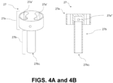
- the airflow member 27 has an airflow bridge 27a and an airflow duct 27b made in one piece, the airflow bridge 27a having two airway openings 27a' forming a portion of the inhalation channel 20 and the airflow duct 27b extending in the sonication chamber 22 from the airflow bridge 27a for providing the air flow from the surroundings to the sonication chamber.
- the airflow bridge 27a cooperates with the frustoconical element 20a at the second diameter 20a2.
- the airflow bridge 27a has two opposite peripheral openings 27a" providing air flow to the airflow duct 27b.
- the cooperation with the airflow bridge 27a and the frustoconical element 20a is arranged so that the two opposite peripheral openings 27a" cooperate with complementary openings 20a" in the frustoconical element 20a.
- the airflow member 27 and the frustoconical element 20a are made in one piece.
- the mouthpiece 1 and the frustoconical element 20a are radially spaced and an airflow chamber 28 is arranged between them.
- the mouthpiece 1 has two opposite peripheral openings 1".
- peripheral openings 27a", 20a", 1" of the airflow bridge 27a, the frustoconical element 20a and the mouthpiece 1 directly supply maximum air flow to the sonication chamber 22.
- the frustoconical element 20a includes an internal passage, aligned in the similar direction as the inhalation channel 20, having a first diameter 20a1 less than that of a second diameter 20a2, such that the internal passage reduces in diameter over the frustoconical element 20a.
- the frustoconical element 20a is positioned in alignment with the means of ultrasonic vibrations 5 and a capillary element 7, wherein the first diameter 20a1 is linked to an inner duct 11 of the mouthpiece 1 and the second diameter 20a2 is linked to the inner container 20b.
- the inner container 20b has an inner wall delimiting the sonication chamber 22 and the liquid chamber 21.
- the liquid reservoir structure 2 has an outer container 20c delimiting the outer wall of the liquid chamber 21.
- the inner container 20b and the outer container 20c are respectively the inner wall and the outer wall of the liquid chamber 21.
- the liquid reservoir structure 2 is arranged between the mouthpiece 1 and the casing 3 and is detachable from the mouthpiece 1 and the casing 3.
- the liquid reservoir structure 2 and the mouthpiece 1 or the casing 3 may include complimentary arrangements for engaging with one another; further such complimentary arrangements may include one of the following: a bayonet type arrangement; a threaded engaged type arrangement; a magnetic arrangement; or a friction fit arrangement; wherein the liquid reservoir structure 2 includes a portion of the arrangement and the mouthpiece 1 or the casing 3 includes the complimentary portion of the arrangement.
- the components are substantially the same.
- the differences in the reusable embodiment vis-a-vis the disposable embodiment are the accommodations made to replace the liquid reservoir structure 2.
- the liquid chamber 21 has a top wall 23 and a bottom wall 25 closing the inner container 20b and the outer container 20c of the liquid chamber 21.
- the capillary element 7 is arranged between a first section 20b1 and a second section 20b2 of the inner container 20b.
- the capillary element 7 has a flat shape extending from the sonication chamber to the liquid chamber.
- the capillary element 7 comprises a central portion 7a in U-shape and a peripheral portion 7b in L-shape.
- the L-shape portion 7b extends into the liquid chamber 21 on the inner container 20b and along the bottom wall 25.
- the U-shape portion 7a is contained into the sonication chamber 21.
- the U-shape portion 7a on the inner container 20b and along the bottom wall 25.
- the U-shape portion 7a has an inner portion 7a1 and an outer portion 7a2, the inner portion 7a1 being in surface contact with an atomization surface 50 of the means of ultrasonic vibrations 5 and the outer portion 7a2 being not in surface contact with the means of ultrasonic vibrations 5.
- the bottom wall 25 of the liquid chamber 21 is a bottom plate 25 closing the liquid chamber 21 and the sonication chamber 22.
- the bottom plate 25 is sealed, thus preventing leakage of liquid from the sonication chamber 22 to the casing 3.
- the bottom plate 25 has an upper surface 25a having a recess 25b on which is inserted an elastic member 8.
- the means of ultrasonic vibrations 5 are supported by the elastic member 8.
- the elastic member 8 is formed from an annular plate-shaped rubber having an inner hole 8' wherein a groove is designed for maintaining the means of ultrasonic vibrations 5.
- the top wall 23 of the liquid chamber 21 is a cap 23 closing the liquid chamber 23.
- the top wall 23 has a top surface 23 representing the maximum level of the liquid that the liquid chamber 21 may contain and the bottom surface 25 representing the minimum level of the liquid in the liquid chamber 21.
- the top wall 23 is sealed, thus preventing leakage of liquid from the liquid chamber 21 to the mouthpiece 1.
- the top wall 23 and the bottom wall 25 are fixed to the liquid reservoir structure 2 by means of fixation such as screws, glue or friction.
- the elastic member 8 is in line contact with the means of ultrasonic vibrations 5 and prevents contact between the means of ultrasonic vibrations 5 and the inhaler walls, suppression of vibrations of the liquid reservoir structure are more effectively prevented. Thus, fine particles of the liquid atomized by the atomizing member can be sprayed farther.
- the inner container 20b has openings 20b' between the first section 20b1 and the second section 20b2 from which the capillary element 7 is extending from the sonication chamber 21.
- the capillary element 7 absorbs liquid from the liquid chamber 21 through the apertures 20b'.
- the capillary element 7 is a wick.
- the capillary element 7 transports liquid to the sonication chamber 22 via capillary action.
- the capillary element 7 is made of bamboo fibers; however, cotton, paper, or other fiber strands could be used for a wick material.
- the means of ultrasonic vibrations 5 are disposed directly below the capillary element 7.
- the means of ultrasonic vibrations 5 may be a transducer.
- the means of ultrasonic vibrations 5 may be a piezoelectric transducer, preferably designed in a circular plate-shape.
- the material of the piezoelectric transducer is preferably in ceramic.
- transducer materials can also be used for the means of ultrasonic vibrations 5.
- the end of the airflow duct 27b1 faces the means of ultrasonic vibrations 5.
- the means of ultrasonic vibrations 5 are in electrical communication with electrical contactors 101a, 101b.
- the distal end 4b of the integrated circuit 4 has an inner electrode and an outer electrode.
- the inner electrode contacts the first electrical contact 101a which is a spring contact probe, and the outer electrode contacts the second electrical contact 101b which is a side pin.
- the first electrical contact 101a is in electrical communication with the positive terminal of the electrical storage device 30 by way of the microprocessor, while the second electrical contact 101b is in electrical communication with the negative terminal of the electrical storage device 30.
- the electrical contacts 101a, 101b crossed the bottom plate 25.
- the bottom plate 25 is designed to be received inside the perimeter wall 26 of the liquid reservoir structure 2.
- the bottom plate 25 rests on complementary ridges, thereby creating the liquid chamber 21 and sonication chamber 22.
- the inner container 20b comprises a circular inner slot 20d on which a mechanical spring is applied.
- the mechanical spring 9 By pushing the central portion 7a1 onto the means of ultrasonic vibrations 5, the mechanical spring 9 ensures a contact surface between them.
- the liquid reservoir structure 2 and the bottom plate 25 can be made using a variety of thermoplastic materials.
- the sensor activates the integrated circuit 4, which triggers the means of ultrasonic vibrations 5 to begin vibrating.
- the draw reduces the pressure outside the reservoir chamber 21 such that flow of the liquid through the apertures 20b' begins, which saturates the capillary element 7.
- the capillary element 7 transports the liquid to the means of ultrasonic vibrations 5, which causes bubbles to form in a capillary channel by the means of ultrasonic vibrations 5 and mist the liquid. Then, the mist liquid is drawn by the user.
- the ultrasonic mist inhaler 100 of the present disclosures is a more powerful version of current portable medical nebulizers, in the shape and size of current e-cigarettes and with a particular structure for effective vaporization. It is a healthier alternative to cigarettes and current e-cigarettes products.
- the ultrasonic mist inhaler 100 of the present disclosures has particular applicability for those who use electronic inhalers as a means to quit smoking and reduce their nicotine dependency.
- the ultrasonic mist inhaler 100 provides a way to gradually taper the dose of nicotine.
Landscapes
- Health & Medical Sciences (AREA)
- Engineering & Computer Science (AREA)
- Life Sciences & Earth Sciences (AREA)
- Public Health (AREA)
- Anesthesiology (AREA)
- Biomedical Technology (AREA)
- Heart & Thoracic Surgery (AREA)
- Hematology (AREA)
- Veterinary Medicine (AREA)
- Animal Behavior & Ethology (AREA)
- General Health & Medical Sciences (AREA)
- Pulmonology (AREA)
- Bioinformatics & Cheminformatics (AREA)
- Mechanical Engineering (AREA)
- Chemical & Material Sciences (AREA)
- Chemical Kinetics & Catalysis (AREA)
- General Chemical & Material Sciences (AREA)
- Special Spraying Apparatus (AREA)
- Medicinal Preparation (AREA)
Claims (6)
- Inhalateur de brume ultrasonique, comprenant :une structure de réservoir de liquide (2) comprenant une chambre à liquide (21) adaptée pour recevoir le liquide à atomiser,une chambre de sonification (22) en communication fluidique avec la chambre à liquide (21),un moyen de vibrations ultrasoniques (5) configuré pour générer des ondes ultrasoniques à l'intérieur de la chambre de sonification (22) ;un embout buccal (1) pour l'inhalation de la brume ;un élément de circulation d'air (27) qui est fourni à l'intérieur d'une partie de la structure de réservoir de liquide (2), dans lequel l'élément de circulation d'air (27) comprend :un pont d'écoulement d'air (27a) ayant au moins une ouverture de passage d'air (27a') qui fait partie d'un canal d'inhalation (20) allant de la chambre de sonification (22) à un embout buccal (1), etun conduit d'écoulement d'air allongé (27b) ayant une première extrémité accouplée au pont d'écoulement d'air (27a) et une seconde extrémité positionnée de manière adjacente et face au moyen de vibrations ultrasoniques (5),dans lequel le pont d'écoulement d'air (27a) comprend en outre une ouverture périphérique (27a") qui fournit un chemin d'écoulement d'air depuis l'environnement de l'inhalateur de brume ultrasonique (100) vers une chambre d'écoulement d'air (28), puis vers la première extrémité du conduit d'écoulement d'air (27b), de sorte que l'élément d'écoulement d'air (27) fournit un écoulement d'air depuis l'environnement à travers le conduit d'écoulement d'air (27b) vers la chambre de sonification (22) et hors de la chambre de sonification (22) à travers le canal d'inhalation (20) au moment de l'inhalation, dans lequel le pont d'écoulement d'air (27a) est en prise avec un élément tronconique (20a) qui comprend au moins une ouverture périphérique (20a") alignée avec l'ouverture périphérique (27a") du pont d'écoulement d'air (27a), et dans lequel la chambre d'écoulement d'air (28) est disposée entre l'embout buccal (1) et l'élément tronconique (20a).
- Inhalateur de brume ultrasonique selon la revendication 1, dans lequel l'embout buccal (1) comprend au moins une ouverture périphérique (1") alignée avec l'ouverture périphérique (27a") du pont d'écoulement d'air (27a) et l'ouverture périphérique (20a") de l'élément tronconique (20a).
- Inhalateur de brume ultrasonique selon l'une quelconque des revendications précédentes, dans lequel un élément capillaire (7) est disposé entre la chambre à liquide (21) et la chambre de sonification (22).
- Inhalateur de brume ultrasonique selon la revendication 3, dans lequel la seconde extrémité du conduit d'écoulement d'air (27b) s'étend dans la chambre de sonification (22) et est proche ou au niveau de l'élément capillaire (7).
- Inhalateur de brume ultrasonique selon l'une quelconque des revendications précédentes, dans lequel le pont d'écoulement d'air (27a) et le conduit d'écoulement d'air (27b) sont fabriqués en une seule pièce.
- Inhalateur de brume ultrasonique selon l'une quelconque des revendications précédentes, dans lequel ledit liquide à recevoir dans la chambre à liquide (21) comprend de 57 à 70 % (p/p) de glycérine végétale et de 30 à 43 % (p/p) de propylène glycol, ledit propylène glycol comportant de la nicotine et des arômes.
Priority Applications (2)
| Application Number | Priority Date | Filing Date | Title |
|---|---|---|---|
| HUE19956917A HUE071485T2 (hu) | 2019-12-15 | 2019-12-15 | Ultrahangos párainhalátor |
| MA70018A MA70018B1 (fr) | 2019-12-15 | 2019-12-15 | Inhalateur de brume à ultrasons |
Applications Claiming Priority (1)
| Application Number | Priority Date | Filing Date | Title |
|---|---|---|---|
| PCT/IB2019/060809 WO2021123868A1 (fr) | 2019-12-15 | 2019-12-15 | Inhalateur de brume à ultrasons |
Publications (3)
| Publication Number | Publication Date |
|---|---|
| EP4031217A1 EP4031217A1 (fr) | 2022-07-27 |
| EP4031217A4 EP4031217A4 (fr) | 2023-06-21 |
| EP4031217B1 true EP4031217B1 (fr) | 2025-03-26 |
Family
ID=76478215
Family Applications (1)
| Application Number | Title | Priority Date | Filing Date |
|---|---|---|---|
| EP19956917.9A Active EP4031217B1 (fr) | 2019-12-15 | 2019-12-15 | Inhalateur de brume à ultrasons |
Country Status (10)
| Country | Link |
|---|---|
| US (1) | US20220370739A1 (fr) |
| EP (1) | EP4031217B1 (fr) |
| JP (1) | JP7480337B2 (fr) |
| KR (1) | KR102743594B1 (fr) |
| ES (1) | ES3017733T3 (fr) |
| HU (1) | HUE071485T2 (fr) |
| MA (1) | MA70018B1 (fr) |
| MD (1) | MD4031217T2 (fr) |
| PL (1) | PL4031217T3 (fr) |
| WO (1) | WO2021123868A1 (fr) |
Families Citing this family (6)
| Publication number | Priority date | Publication date | Assignee | Title |
|---|---|---|---|---|
| US12501929B2 (en) | 2018-08-22 | 2025-12-23 | Qnovia, Inc. | Electronic device for producing an aerosol for inhalation by a person |
| US20200060338A1 (en) | 2018-08-22 | 2020-02-27 | Respira Technologies, Inc. | Electronic device for producing an aerosol for inhalation by a person |
| US20210113783A1 (en) | 2019-10-20 | 2021-04-22 | Respira Technologies, Inc. | Electronic devices and liquids for aerosolizing and inhaling therewith |
| US12471625B2 (en) | 2020-11-01 | 2025-11-18 | Qnovia, Inc. | Electronic devices and liquids for aerosolizing and inhaling therewith |
| CA3261770A1 (fr) | 2022-04-22 | 2023-10-26 | Qnovia, Inc. | Dispositifs électroniques pour vaporiser et inhaler un liquide |
| TWI885825B (zh) * | 2024-03-27 | 2025-06-01 | 董醒華 | 密封式霧化器儲液裝置 |
Family Cites Families (6)
| Publication number | Priority date | Publication date | Assignee | Title |
|---|---|---|---|---|
| AU2016422051B2 (en) * | 2016-08-31 | 2020-03-12 | China Tobacco Hunan Industrial Co., Ltd. | Ultrasonic electronic cigarette atomizing core and atomizer |
| CN108078009B (zh) * | 2016-11-22 | 2024-02-27 | 湖南中烟工业有限责任公司 | 斜置超声雾化片结构及雾化器、电子烟 |
| CN206303211U (zh) * | 2016-12-20 | 2017-07-07 | 湖南中烟工业有限责任公司 | 一种超声波雾化电子烟 |
| WO2019052506A1 (fr) * | 2017-09-13 | 2019-03-21 | 湖南中烟工业有限责任公司 | Atomiseur de cigarette électronique ultrasonore |
| GB201807154D0 (en) * | 2018-05-01 | 2018-06-13 | Nerudia Ltd | Smoking substitute system |
| CN208354603U (zh) * | 2018-06-22 | 2019-01-11 | 湖南中烟工业有限责任公司 | 一种电子烟雾化器及该电子烟 |
-
2019
- 2019-12-15 US US17/772,368 patent/US20220370739A1/en active Pending
- 2019-12-15 JP JP2022561691A patent/JP7480337B2/ja active Active
- 2019-12-15 MA MA70018A patent/MA70018B1/fr unknown
- 2019-12-15 HU HUE19956917A patent/HUE071485T2/hu unknown
- 2019-12-15 WO PCT/IB2019/060809 patent/WO2021123868A1/fr not_active Ceased
- 2019-12-15 MD MDE20220809T patent/MD4031217T2/ro unknown
- 2019-12-15 EP EP19956917.9A patent/EP4031217B1/fr active Active
- 2019-12-15 KR KR1020227024458A patent/KR102743594B1/ko active Active
- 2019-12-15 ES ES19956917T patent/ES3017733T3/es active Active
- 2019-12-15 PL PL19956917.9T patent/PL4031217T3/pl unknown
Also Published As
| Publication number | Publication date |
|---|---|
| KR20220141287A (ko) | 2022-10-19 |
| MD4031217T2 (ro) | 2025-07-31 |
| HUE071485T2 (hu) | 2025-08-28 |
| ES3017733T3 (en) | 2025-05-13 |
| PL4031217T3 (pl) | 2025-06-16 |
| MA70018B1 (fr) | 2025-04-30 |
| EP4031217A1 (fr) | 2022-07-27 |
| EP4031217A4 (fr) | 2023-06-21 |
| JP2023506331A (ja) | 2023-02-15 |
| WO2021123868A1 (fr) | 2021-06-24 |
| JP7480337B2 (ja) | 2024-05-09 |
| US20220370739A1 (en) | 2022-11-24 |
| KR102743594B1 (ko) | 2024-12-18 |
Similar Documents
| Publication | Publication Date | Title |
|---|---|---|
| EP4031216B1 (fr) | Nébulisateur à ultrasons | |
| US12403272B2 (en) | Ultrasonic mist inhaler | |
| US12262746B2 (en) | Ultrasonic mist inhaler for atomizing a liquid by ultrasonic vibrations | |
| US20250194671A1 (en) | Ultrasonic mist inhaler | |
| US12290098B2 (en) | Ultrasonic mist inhaler with capillary retainer | |
| US20220370739A1 (en) | Ultrasonic mist inhaler | |
| EP3834636A1 (fr) | Dispositif d'inhalation de brouillard ultrasonique | |
| HK40104424A (en) | Ultrasonic mist inhaler | |
| HK40104424B (en) | Ultrasonic mist inhaler |
Legal Events
| Date | Code | Title | Description |
|---|---|---|---|
| STAA | Information on the status of an ep patent application or granted ep patent |
Free format text: STATUS: THE INTERNATIONAL PUBLICATION HAS BEEN MADE |
|
| PUAI | Public reference made under article 153(3) epc to a published international application that has entered the european phase |
Free format text: ORIGINAL CODE: 0009012 |
|
| STAA | Information on the status of an ep patent application or granted ep patent |
Free format text: STATUS: REQUEST FOR EXAMINATION WAS MADE |
|
| 17P | Request for examination filed |
Effective date: 20220420 |
|
| AK | Designated contracting states |
Kind code of ref document: A1 Designated state(s): AL AT BE BG CH CY CZ DE DK EE ES FI FR GB GR HR HU IE IS IT LI LT LU LV MC MK MT NL NO PL PT RO RS SE SI SK SM TR |
|
| RAP3 | Party data changed (applicant data changed or rights of an application transferred) |
Owner name: SHAHEEN INNOVATIONS HOLDING LIMITED |
|
| RIN1 | Information on inventor provided before grant (corrected) |
Inventor name: ALSHAIBA SALEH GHANNAM ALMAZROUEI, MOHAMMED Inventor name: LAHOUD, IMAD |
|
| A4 | Supplementary search report drawn up and despatched |
Effective date: 20230522 |
|
| RIC1 | Information provided on ipc code assigned before grant |
Ipc: A24F 40/10 20200101ALI20230515BHEP Ipc: A24F 40/05 20200101ALI20230515BHEP Ipc: A61M 15/06 20060101ALI20230515BHEP Ipc: B05B 17/06 20060101ALI20230515BHEP Ipc: A61M 15/00 20060101AFI20230515BHEP |
|
| RIN1 | Information on inventor provided before grant (corrected) |
Inventor name: THE OTHER INVENTOR HAS WAIVED HIS RIGHT TO BE THUS MENTIONED. Inventor name: ALSHAIBA SALEH GHANNAM ALMAZROUEI, MOHAMMED |
|
| STAA | Information on the status of an ep patent application or granted ep patent |
Free format text: STATUS: EXAMINATION IS IN PROGRESS |
|
| 17Q | First examination report despatched |
Effective date: 20240315 |
|
| GRAP | Despatch of communication of intention to grant a patent |
Free format text: ORIGINAL CODE: EPIDOSNIGR1 |
|
| STAA | Information on the status of an ep patent application or granted ep patent |
Free format text: STATUS: GRANT OF PATENT IS INTENDED |
|
| RIC1 | Information provided on ipc code assigned before grant |
Ipc: A61M 11/00 20060101ALI20241216BHEP Ipc: A24F 40/10 20200101ALI20241216BHEP Ipc: A24F 40/05 20200101ALI20241216BHEP Ipc: A61M 15/06 20060101ALI20241216BHEP Ipc: B05B 17/06 20060101ALI20241216BHEP Ipc: A61M 15/00 20060101AFI20241216BHEP |
|
| GRAS | Grant fee paid |
Free format text: ORIGINAL CODE: EPIDOSNIGR3 |
|
| INTG | Intention to grant announced |
Effective date: 20250113 |
|
| GRAA | (expected) grant |
Free format text: ORIGINAL CODE: 0009210 |
|
| STAA | Information on the status of an ep patent application or granted ep patent |
Free format text: STATUS: THE PATENT HAS BEEN GRANTED |
|
| P01 | Opt-out of the competence of the unified patent court (upc) registered |
Free format text: CASE NUMBER: APP_3564/2025 Effective date: 20250122 |
|
| AK | Designated contracting states |
Kind code of ref document: B1 Designated state(s): AL AT BE BG CH CY CZ DE DK EE ES FI FR GB GR HR HU IE IS IT LI LT LU LV MC MK MT NL NO PL PT RO RS SE SI SK SM TR |
|
| REG | Reference to a national code |
Ref country code: GB Ref legal event code: FG4D Ref country code: TN Ref legal event code: VAGR Ref document number: TN/P/2025/0110 Country of ref document: TN |
|
| REG | Reference to a national code |
Ref country code: CH Ref legal event code: EP |
|
| REG | Reference to a national code |
Ref country code: DE Ref legal event code: R096 Ref document number: 602019067969 Country of ref document: DE |
|
| REG | Reference to a national code |
Ref country code: IE Ref legal event code: FG4D Ref country code: NL Ref legal event code: FP |
|
| REG | Reference to a national code |
Ref country code: MA Ref legal event code: VAGR Ref document number: 70018 Country of ref document: MA Kind code of ref document: B1 |
|
| REG | Reference to a national code |
Ref country code: ES Ref legal event code: FG2A Ref document number: 3017733 Country of ref document: ES Kind code of ref document: T3 Effective date: 20250513 |
|
| PG25 | Lapsed in a contracting state [announced via postgrant information from national office to epo] |
Ref country code: RS Free format text: LAPSE BECAUSE OF FAILURE TO SUBMIT A TRANSLATION OF THE DESCRIPTION OR TO PAY THE FEE WITHIN THE PRESCRIBED TIME-LIMIT Effective date: 20250626 |
|
| PG25 | Lapsed in a contracting state [announced via postgrant information from national office to epo] |
Ref country code: FI Free format text: LAPSE BECAUSE OF FAILURE TO SUBMIT A TRANSLATION OF THE DESCRIPTION OR TO PAY THE FEE WITHIN THE PRESCRIBED TIME-LIMIT Effective date: 20250326 |
|
| REG | Reference to a national code |
Ref country code: LT Ref legal event code: MG9D |
|
| PG25 | Lapsed in a contracting state [announced via postgrant information from national office to epo] |
Ref country code: NO Free format text: LAPSE BECAUSE OF FAILURE TO SUBMIT A TRANSLATION OF THE DESCRIPTION OR TO PAY THE FEE WITHIN THE PRESCRIBED TIME-LIMIT Effective date: 20250626 |
|
| PG25 | Lapsed in a contracting state [announced via postgrant information from national office to epo] |
Ref country code: HR Free format text: LAPSE BECAUSE OF FAILURE TO SUBMIT A TRANSLATION OF THE DESCRIPTION OR TO PAY THE FEE WITHIN THE PRESCRIBED TIME-LIMIT Effective date: 20250326 |
|
| PG25 | Lapsed in a contracting state [announced via postgrant information from national office to epo] |
Ref country code: LV Free format text: LAPSE BECAUSE OF FAILURE TO SUBMIT A TRANSLATION OF THE DESCRIPTION OR TO PAY THE FEE WITHIN THE PRESCRIBED TIME-LIMIT Effective date: 20250326 |
|
| PG25 | Lapsed in a contracting state [announced via postgrant information from national office to epo] |
Ref country code: BG Free format text: LAPSE BECAUSE OF FAILURE TO SUBMIT A TRANSLATION OF THE DESCRIPTION OR TO PAY THE FEE WITHIN THE PRESCRIBED TIME-LIMIT Effective date: 20250326 |
|
| REG | Reference to a national code |
Ref country code: MD Ref legal event code: VAGR Ref document number: 4031217 Country of ref document: MD Date of ref document: 20250731 Kind code of ref document: T2 |
|
| REG | Reference to a national code |
Ref country code: GR Ref legal event code: EP Ref document number: 20250400853 Country of ref document: GR Effective date: 20250613 |
|
| REG | Reference to a national code |
Ref country code: HU Ref legal event code: AG4A Ref document number: E071485 Country of ref document: HU |
|
| PG25 | Lapsed in a contracting state [announced via postgrant information from national office to epo] |
Ref country code: SE Free format text: LAPSE BECAUSE OF FAILURE TO SUBMIT A TRANSLATION OF THE DESCRIPTION OR TO PAY THE FEE WITHIN THE PRESCRIBED TIME-LIMIT Effective date: 20250326 |
|
| PG25 | Lapsed in a contracting state [announced via postgrant information from national office to epo] |
Ref country code: SM Free format text: LAPSE BECAUSE OF FAILURE TO SUBMIT A TRANSLATION OF THE DESCRIPTION OR TO PAY THE FEE WITHIN THE PRESCRIBED TIME-LIMIT Effective date: 20250326 |
|
| PG25 | Lapsed in a contracting state [announced via postgrant information from national office to epo] |
Ref country code: PT Free format text: LAPSE BECAUSE OF FAILURE TO SUBMIT A TRANSLATION OF THE DESCRIPTION OR TO PAY THE FEE WITHIN THE PRESCRIBED TIME-LIMIT Effective date: 20250728 |
|
| PG25 | Lapsed in a contracting state [announced via postgrant information from national office to epo] |
Ref country code: EE Free format text: LAPSE BECAUSE OF FAILURE TO SUBMIT A TRANSLATION OF THE DESCRIPTION OR TO PAY THE FEE WITHIN THE PRESCRIBED TIME-LIMIT Effective date: 20250326 |
|
| PG25 | Lapsed in a contracting state [announced via postgrant information from national office to epo] |
Ref country code: RO Free format text: LAPSE BECAUSE OF FAILURE TO SUBMIT A TRANSLATION OF THE DESCRIPTION OR TO PAY THE FEE WITHIN THE PRESCRIBED TIME-LIMIT Effective date: 20250326 |
|
| PG25 | Lapsed in a contracting state [announced via postgrant information from national office to epo] |
Ref country code: SK Free format text: LAPSE BECAUSE OF FAILURE TO SUBMIT A TRANSLATION OF THE DESCRIPTION OR TO PAY THE FEE WITHIN THE PRESCRIBED TIME-LIMIT Effective date: 20250326 |
|
| PG25 | Lapsed in a contracting state [announced via postgrant information from national office to epo] |
Ref country code: IS Free format text: LAPSE BECAUSE OF FAILURE TO SUBMIT A TRANSLATION OF THE DESCRIPTION OR TO PAY THE FEE WITHIN THE PRESCRIBED TIME-LIMIT Effective date: 20250726 |
|
| REG | Reference to a national code |
Ref country code: CH Ref legal event code: U11 Free format text: ST27 STATUS EVENT CODE: U-0-0-U10-U11 (AS PROVIDED BY THE NATIONAL OFFICE) Effective date: 20260101 |
|
| REG | Reference to a national code |
Ref country code: DE Ref legal event code: R097 Ref document number: 602019067969 Country of ref document: DE |
|
| PGFP | Annual fee paid to national office [announced via postgrant information from national office to epo] |
Ref country code: DE Payment date: 20251211 Year of fee payment: 7 |
|
| PGFP | Annual fee paid to national office [announced via postgrant information from national office to epo] |
Ref country code: GB Payment date: 20251204 Year of fee payment: 7 |
|
| PG25 | Lapsed in a contracting state [announced via postgrant information from national office to epo] |
Ref country code: DK Free format text: LAPSE BECAUSE OF FAILURE TO SUBMIT A TRANSLATION OF THE DESCRIPTION OR TO PAY THE FEE WITHIN THE PRESCRIBED TIME-LIMIT Effective date: 20250326 |
|
| PGFP | Annual fee paid to national office [announced via postgrant information from national office to epo] |
Ref country code: AT Payment date: 20251222 Year of fee payment: 7 |
|
| PGFP | Annual fee paid to national office [announced via postgrant information from national office to epo] |
Ref country code: IT Payment date: 20251222 Year of fee payment: 7 |
|
| PGFP | Annual fee paid to national office [announced via postgrant information from national office to epo] |
Ref country code: HU Payment date: 20251223 Year of fee payment: 7 Ref country code: NL Payment date: 20251219 Year of fee payment: 7 Ref country code: FR Payment date: 20251229 Year of fee payment: 7 |
|
| VSFP | Annual fee paid to validation state [announced via postgrant information from national office to epo] |
Ref country code: MD Payment date: 20251206 Year of fee payment: 7 |
|
| PGFP | Annual fee paid to national office [announced via postgrant information from national office to epo] |
Ref country code: TR Payment date: 20251209 Year of fee payment: 7 Ref country code: GR Payment date: 20251222 Year of fee payment: 7 Ref country code: BE Payment date: 20251219 Year of fee payment: 7 |
|
| PGFP | Annual fee paid to national office [announced via postgrant information from national office to epo] |
Ref country code: IE Payment date: 20251219 Year of fee payment: 7 Ref country code: CZ Payment date: 20251210 Year of fee payment: 7 |
|
| PGFP | Annual fee paid to national office [announced via postgrant information from national office to epo] |
Ref country code: PL Payment date: 20251204 Year of fee payment: 7 |
|
| PLBE | No opposition filed within time limit |
Free format text: ORIGINAL CODE: 0009261 |
|
| STAA | Information on the status of an ep patent application or granted ep patent |
Free format text: STATUS: NO OPPOSITION FILED WITHIN TIME LIMIT |
|
| REG | Reference to a national code |
Ref country code: CH Ref legal event code: L10 Free format text: ST27 STATUS EVENT CODE: U-0-0-L10-L00 (AS PROVIDED BY THE NATIONAL OFFICE) Effective date: 20260211 |
|
| VSFP | Annual fee paid to validation state [announced via postgrant information from national office to epo] |
Ref country code: MA Payment date: 20251216 Year of fee payment: 7 |
|
| 26N | No opposition filed |
Effective date: 20260105 |
|
| PGFP | Annual fee paid to national office [announced via postgrant information from national office to epo] |
Ref country code: ES Payment date: 20260130 Year of fee payment: 7 |
|
| PGFP | Annual fee paid to national office [announced via postgrant information from national office to epo] |
Ref country code: CH Payment date: 20260101 Year of fee payment: 7 |