EP4031286B1 - Pot jetable de centrifugeuse - Google Patents
Pot jetable de centrifugeuse Download PDFInfo
- Publication number
- EP4031286B1 EP4031286B1 EP20780277.8A EP20780277A EP4031286B1 EP 4031286 B1 EP4031286 B1 EP 4031286B1 EP 20780277 A EP20780277 A EP 20780277A EP 4031286 B1 EP4031286 B1 EP 4031286B1
- Authority
- EP
- European Patent Office
- Prior art keywords
- pot
- baffles
- cartridge according
- consumable cartridge
- central axis
- Prior art date
- Legal status (The legal status is an assumption and is not a legal conclusion. Google has not performed a legal analysis and makes no representation as to the accuracy of the status listed.)
- Active
Links
Images






Classifications
-
- B—PERFORMING OPERATIONS; TRANSPORTING
- B04—CENTRIFUGAL APPARATUS OR MACHINES FOR CARRYING-OUT PHYSICAL OR CHEMICAL PROCESSES
- B04B—CENTRIFUGES
- B04B7/00—Elements of centrifuges
- B04B7/08—Rotary bowls
- B04B7/12—Inserts, e.g. armouring plates
-
- B—PERFORMING OPERATIONS; TRANSPORTING
- B04—CENTRIFUGAL APPARATUS OR MACHINES FOR CARRYING-OUT PHYSICAL OR CHEMICAL PROCESSES
- B04B—CENTRIFUGES
- B04B1/00—Centrifuges with rotary bowls provided with solid jackets for separating predominantly liquid mixtures with or without solid particles
-
- B—PERFORMING OPERATIONS; TRANSPORTING
- B04—CENTRIFUGAL APPARATUS OR MACHINES FOR CARRYING-OUT PHYSICAL OR CHEMICAL PROCESSES
- B04B—CENTRIFUGES
- B04B1/00—Centrifuges with rotary bowls provided with solid jackets for separating predominantly liquid mixtures with or without solid particles
- B04B1/04—Centrifuges with rotary bowls provided with solid jackets for separating predominantly liquid mixtures with or without solid particles with inserted separating walls
- B04B1/06—Centrifuges with rotary bowls provided with solid jackets for separating predominantly liquid mixtures with or without solid particles with inserted separating walls of cylindrical shape
-
- B—PERFORMING OPERATIONS; TRANSPORTING
- B04—CENTRIFUGAL APPARATUS OR MACHINES FOR CARRYING-OUT PHYSICAL OR CHEMICAL PROCESSES
- B04B—CENTRIFUGES
- B04B5/00—Other centrifuges
- B04B5/04—Radial chamber apparatus for separating predominantly liquid mixtures, e.g. butyrometers
-
- B—PERFORMING OPERATIONS; TRANSPORTING
- B04—CENTRIFUGAL APPARATUS OR MACHINES FOR CARRYING-OUT PHYSICAL OR CHEMICAL PROCESSES
- B04B—CENTRIFUGES
- B04B5/00—Other centrifuges
- B04B5/04—Radial chamber apparatus for separating predominantly liquid mixtures, e.g. butyrometers
- B04B5/0407—Radial chamber apparatus for separating predominantly liquid mixtures, e.g. butyrometers for liquids contained in receptacles
-
- B—PERFORMING OPERATIONS; TRANSPORTING
- B04—CENTRIFUGAL APPARATUS OR MACHINES FOR CARRYING-OUT PHYSICAL OR CHEMICAL PROCESSES
- B04B—CENTRIFUGES
- B04B7/00—Elements of centrifuges
- B04B7/08—Rotary bowls
Definitions
- the present disclosure relates to pots for use in centrifugal separation of biological liquids into different phases (for example in diagnostics, therapeutics, sample preparation).
- the disclosure also relates to consumable cartridges suitable for use with centrifuge instruments and point-of-care diagnostic instruments.
- a common requirement is to be able to separate a whole blood sample into its liquid plasma component separated from the cellular matter of the blood (red and white blood cells).
- the sample is spun at high speed in a bench-top laboratory centrifuge which separates the blood into components according to their relative densities with the lighter liquid plasma remaining on top of the tube after spinning and available to be aspirated off.
- the sample In order to generate the centrifugal force necessary to achieve separation of the blood, the sample is spun some distance away from an axis at high speed. This is often achieved by using sample tubes placed 5-20cm away from the rotational axis and at an angle of 20-45deg from the vertical. The angled tubes help to maintain the plasma and blood separation as the centrifuge comes to a stop.
- centrifuges either require significant manual intervention to load and unload the sample and extract the generated plasma, or a large and complex machine is required to automate this process limiting it to, for example central lab instruments.
- the first is the use of a separation filter instead of centrifugation to separate the blood from plasma.
- a separation filter instead of centrifugation to separate the blood from plasma.
- the Pall Vivid Membrane This works by size filtration, trapping the cells that are too large to pass through the filter.
- this approach is slow, relying on capillary action to wick the sample through the membrane, inefficient with only a maximum of typically 80% of available plasma extracted, prone to contamination as the filter can cause cells to lyse releasing harmful cell contents into the plasma, and filters can typically only process up to ⁇ 100uL of blood sample input before they get clogged with cells.
- a second example is the use of a micro-fluidic centrifugal disc where the entire fluidic system is built on a rotating platform that includes specific elements to separate a blood sample into plasma in the same device.
- this restricts its use to those workflows that can be built into a rotating fluidic disc and the maximum volumes are again limited to those that can easily be accommodated on micro-fluidic discs, typically of the order of 100uL.
- the current art is missing a device that is suitable for separating larger volumes (>500ul) of blood into plasma in a way that could be integrated into a simple fluidic cartridge for use at the point of care.
- WO 97/12679 A1 describes a method for rapid separation of serum or plasma from cells in a whole blood sample uses a cylindrical sample tube having longitudinally-extending internal ribs. A separation gel and the sample are introduced into the tube, and the tube is axially centrifuged so as to form concentric shells of cells, gel, and serum or plasma.
- the serum or plasma collects in the tube by gravity flow and the cells and gel remain affixed to the walls and ribs of the tube.
- US 2,833,103 describes a centrifuge for separating the plasma and red cells of blood into segregated constituent volumes, comprising a vessel rotatable about a vertical axis to perform a centrifuging operation and having defined at the bottom thereof a central well and a trough disposed radially outwardly thereof, said well having an outer periphery defining the inner side wall of said trough, said trough having an open upper end at the periphery of the well and the latter being inclined downwardly from its periphery to the axis of rotation, whereby, with said trough having a capacity not less than the separate constituent red cell volume in a predetermined volume of blood received in said vessel for centrifuging but less than said predetermined volume of blood, said trough, upon completion of the centrifuging operation, will contain all of the said separate constituent red cell volume of said predetermined volume of blood, said vessel having a bottom wall provided with said well and an outer side wall extending upwardly therefrom, said outer side wall being conical and con
- a storage part forming a storage space includes a trap part which forms a trap space of a capacity capable of storing a high-specific-gravity ingredient when the analyte is centrifuged to form a layer structure on the outer peripheral side of the storage space, an inclined inner wall part which decreases gradually in diameter and connects the portion from the trap part to the bottom part, and a guide part which is provided at a position crossing the area where the layer structure is to be formed so as to be directed from the trap part toward the inclined inner wall part in order to guide low-specific-gravity ingredients in the layer structure flowing under the inertial force produced by deceleration of rotation to the inclined inner wall part.
- EP 1542020 A2 describes an analyzer, preferably a desktop analyzer, that includes: a component transport system; a liquid dispense or aspirating station; a member removably located on the transport system.
- the removable holder includes: a probe tip dispenser; a fluid supply section for holding a sample; a test element recess for holding one or more test elements or test element holders, wherein the removable holder is configured to contain the test element recess such that a test element can be acted upon by the liquid dispense or aspirating station, while the test element is in the recess; and a measurement device to analyze a sample.
- a removable centrifuge model on the transport system, which separates samples, such as whole blood before analysis.
- EP 2842633 A1 describes a device for separating materials of different densities.
- a cup body has an internal cavity configured to hold media.
- An inner wall defines a central body region having an upper and lower end. The upper end is wider than the lower end.
- An interior shoulder circumscribes the upper end of the central body region.
- the interior shoulder defines a neck region above the central body region and a shoulder trap below the neck region.
- the shoulder trap circumscribes the upper end of the central body region and is wider than the neck region.
- the present disclosure provides a solution using a pot which is adapted to allow centrifugation to take place by spinning the pot about its own axis, thus negating the need for any complex movements or rotations during the process.
- the simplicity afforded by this design allows for the integration of this pot into a disposable cartridge suitable for use in point of care workflows.
- the present disclosure provides a consumable cartridge as set out in claim 1.
- the pot is adapted to be spun on the central axis for centrifugal separation of the biological fluid in the inner volume, wherein the multiple components remain separated once the pot ceases to spin.
- each of the plurality of baffles does not protrude as far as a centre of the pot, and extends along the wall for between half of and all of a distance between the top end and the bottom end.
- the plurality of baffles are substantially equally spaced around the central axis.
- the plurality of baffles comprises a first baffle that protrudes from the wall by a first distance and a second baffle that protrudes from the wall by a second distance, the first distance being different from the second distance.
- the plurality of baffles are each formed as an arc of a curve in a plane defined by the central axis, the curve having a radius between 0.12 and 0.18 of a width of the pot.
- the protrusion from the bottom end is formed around the central axis with a width of approximately half of a width of the pot, and protrudes between 1 mm and 4 mm from the bottom end.
- the centrifugal separation separates plasma towards the central axis, and the pot is adapted to enable a component of the biological fluid to be extracted through an opening in the top end.
- a width of the pot is less than 40 mm.
- a distance between the top end and the bottom end is less than 30 mm.
- the pot is adapted to be spun at at least 10,000 RPM.
- the biological fluid is blood and the multiple components of the biological fluid comprise plasma and cellular matter.
- the consumable cartridge further comprises a second holding means adapted to securely hold the pot in place until the cartridge is inserted into a centrifuge instrument, and to release the pot to spin freely when the cartridge is inserted into the centrifuge instrument.
- the cartridge is adapted to hold the pot at least partly within the cartridge body when the pot is spinning at at least 10,000 RPM.
- the present disclosure provides a rotatable pot that, when spun along its axis, can effect the separation of the cellular matter from blood via centrifugation.
- the cellular matter of the blood remains separated from the liquid portion (plasma) even when the pot comes to a complete stop, or at least decreases a speed of remixing between the separated blood and plasma, thereby extending the time in which it is possible to extract the plasma for analysis.
- the design enables the pot to be integrated within a disposable cartridge to allow the inclusion of a centrifugation step within an existing micro- or meso-fluidic workflow.
- the design of the pot reduces the complexity normally associated with integrating a centrifugation step within a workflow that could be useful, for instance, at the point of care, and can be performed using smaller, lower cost equipment than would conventionally be available in a large-scale central lab.
- Figure 1 illustrates a pot comprising a lower part 110 and an upper part 120.
- the lower part 110 comprises a wall 111 around a central axis 112, and a bottom end 113, which together define an inner volume that can contain a liquid such as blood.
- the wall has a round, cylindrical shape.
- the wall may instead be polygonal, so long as a central axis can be defined.
- the upper part 120 comprises a top end 121 of the pot.
- the upper part 120 further comprises an opening 122 that is a permanently open hole through which contents of the pot may be added or removed. Even in examples where the upper part 120 comprises an opening, the upper part 120 prevents liquid from spilling out of the pot when it is spun.
- Centrifugation of blood separates plasma towards the central axis 112 and therefore including the opening 122 at or near to the middle of the top end 121 enables extraction of separated plasma through the opening 122.
- the upper part 120 is manufactured separately from the lower part 110, and acts as a removable lid for the lower part 110.
- the design of this pot disclosed in this invention can be made using for example, two injection moulded parts.
- the lower part 110 and upper part 120 may instead be formed together as a unitary pot.
- the upper and lower parts of the pot may be welded together or, in another example, blow-moulding may be used to create the pot as a single part.
- the lower part 110 additionally comprises a plurality of baffles 114 protruding from the wall into the inner volume.
- the baffles may take a variety of shapes, as explained below, but in this example the baffles are scalloped.
- the scalloped shape of the baffles has the effect of preventing re-mixing of separated blood and plasma when the pot experiences a decelerating force at the end of centrifugation.
- the baffles may be omitted.
- the pot has a radius of less than 20 mm and a height (i.e. a distance between the top end 121 and the bottom end 113) of less than 30 mm.
- the pot may be cylindrical, in which case “radius” takes its normal meaning. However, this is merely the simplest case and the pot may have a less smooth, polygonal, cross-section. In such alternatives, “radius” refers to half of the average width across the polygonal cross-section, and is alternatively called the "half-width" herein. Therefore, the pot may, more generally, usefully have a width of less than 40 mm.
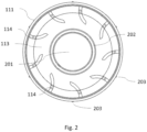
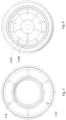
- Figure 2 provides a plan view of the pot in which the baffles can be more easily seen.
- each of the plurality of baffles 114 does not protrude as far as a centre 201 of the pot (corresponding to the central axis 112) and extends along the wall (i.e. out of the plane of Fig. 2 ) for between half of and all of the height of the wall (i.e. the distance between the top end 121 and the bottom end 113). Additionally, in this example, the plurality of baffles 114 are substantially equally spaced around the centre 201 (corresponding to the central axis 112).
- the lower part 110 comprises a protrusion 202 from the bottom end 113.
- the protrusion 202 extends into the inner volume and around the centre 201 (corresponding to the central axis 112).
- Such a protrusion 202 may be formed around the central axis 112 with a radius of approximately half of the radius of the pot.
- the protrusion 202 may take the shape of a circle of about half the radius of the pot.
- the protrusion 202 need not be a smooth shape, and may instead be polygonal.
- the protrusion 202 provides a small inner wall extending from the bottom of the pot. When blood is centrifuged in the pot, this inner wall feature helps to trap separated cellular matter away from the centre 201 of the pot, helping to maintain separation of plasma in the centre of the pot for longer after centrifugation. This effect is particularly enhanced in cases where the protrusion 202 protrudes between 1 mm and 4 mm from the bottom end.
- baffles 114 and the protrusion 202 independently assist in isolating plasma for longer, either the baffles 114 or the protrusion 202, or more preferably both, may be included in examples of the invention.
- the pot of this example includes one or more outer ribs 203 on an external surface of the wall 111. These outer ribs 203 can be provided to engage with a rotor of a centrifuge instrument in order to prevent slipping when the rotor is driving rotation of the pot.
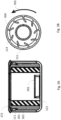
- Fig. 3A represents a pot spinning 4 ml of blood at 12,000 revolutions per minute (RPM) to give 2 ml of cellular matter 301 and 2 ml of plasma 302.
- the pot radius can be as small as, for example, 10 mm - 20 mm which then requires the pot to rotate with an angular velocity of between 10,000 RPM and 20,000 RPM to achieve a relative centrifugal force of between 500g - 2,000g which is typically understood to be required to enable separation of blood from plasma.
- the pot may be adapted to tolerate being spun at at least 10,000 RPM.
- the pot has a symmetric mass balance about its central axis 112 to ensure that there are no significant off-axis mechanical forces generated by the rotation that could damage a centrifuge mechanism with which the pot is used.
- Automatic mass-balancing may be achieved to a large extent by adapting the pot to be spun on its own central axis 112.
- the mass of the blood that is being spun can be of a similar or even greater level than the mass of the pot, the liquid blood will naturally act to compensate for any off-axis or non-symmetric mass distributions in the pot itself.
- This enables the pot to be made via methods that do not require accurate or precise mass distributions. For example, simple plastic injection moulding would be suitable for manufacturing the pot because any resulting irregularities or non-symmetric mass distributions would be compensated for by the mass of the blood spinning within the pot.
- a pot which tolerates high rotational speeds requires that the materials used to construct the pot are of sufficient strength to withstand the centrifugal stresses generated.
- An example of such a suitable material could be polypropylene or polycarbonate.
- Figure 3B is a schematic plan view of the pot during rotation corresponding to Fig. 3A .
- Arrow 303 illustrates a direction of rotation.
- the direction of rotation is chosen such that the baffles 114 curve against the direction of motion. This means that, when the pot slows its rotation, the inertia of the contents of the pot directs the contents into the regions 304 between the baffles 114 and the wall 111.
- the pot described herein is adapted to overcome this limitation, and make aspiration of the plasma 302 without aspirating the cellular material 301 easier and more effective.
- the inclusion of the baffles 114 as shown in Fig. 3B cause the denser cellular material 301, which has greater inertia than the plasma 302, to collect in the regions 304 between the baffles 114 and the wall 111. This prevents the cellular material 301 from moving radially inward as the pot reduces its rotation speed, and prevents the re-mixing of the separated cellular material 301 and plasma 302 upon deceleration. Effectively, the baffles 114 turn the pot into a series of isolated chambers 304, which helps reduce the ability of shear forces of the wall 111 against the cellular material 301 to cause re-mixing.
- the protrusion 202 prevents cellular material 301, which has collected under gravity at the bottom of the pot, from moving towards the centre 201.
- Fig. 3D is a schematic illustration of an example pot when it is slowing down after centrifugation, when it is still rotating at 300 RPM
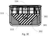
- Fig. 3E is a schematic illustration of the pot just after it has stopped rotating
- the distribution of Fig. 3C is reached by one minute after the pot has stopped rotating.
- Fig. 3D it can be seen that the combination of the baffles 114 and the protrusion 202 has caused the cellular material 301 to settle between the protrusion 202 and the wall 111.
- the continuing rotation at this stage means that the surface of the separated plasma 302 curves upwards away from the central axis 112.
- the pot of the invention provides an opportunity to aspirate the plasma from the centre 201 of the pot without requiring careful alignment of an aspiration means (such as an aspiration needle).
- the above described system enables the pot to be spun on its axis parallel with gravity. This allows for the use of a very simple instrument to carry out the centrifugation and consequently reduces the complexity of the fluidics necessary to collect the generated plasma from the device.
- the pot does not require rotation about any other axis in order to extract the generated plasma from the top of the pot.
- Figures 4A and 4B schematically illustrate a consumable cartridge having a pot as previously described.
- Figure 4A shows the cartridge in an initial fill state where the pot has been filled with 4.5 ml of blood 301, 302.
- Figure 4B shows the cartridge during centrifugation, wherein the pot is rotating in the cartridge at 12,000 RPM and the blood has separated into cellular material 301 and plasma 302.
- Figs. 4A and 4B show a cross-section through the cartridge and through the pot.
- the cartridge has a cartridge body 401 which is cut through in an intended vertical plane of the pot. It can be seen in Figs. 4A and 4B that the cartridge body 401 extends on either side of the pot and the cartridge body 401' also extends around behind the pot, such that the cartridge body 401, 401' is adapted to receive the pot at least partly within the cartridge body. However, the pot may also extend beyond the cartridge body 401, 401' as shown at the bottom of Figs. 4A and 4B .
- the cartridge comprises a dispensing element 402 for dispensing blood 301, 302 into the pot, and an aspirating element 403 for extracting plasma 302 from the pot.
- the dispensing element 402 and aspirating element 403 may approximately take the form of a needle.
- the dispensing element 402 and aspirating element 403 may be attached to the cartridge body 401 or may be formed as part of the cartridge body 401. In this example, the dispensing element 402 and the aspirating element 403 extend through the opening 122 in the top end 121, and remain in the pot during centrifugation as shown in Fig. 4B .
- the aspirating element 403 is located on the central axis 112 of the pot such that it is appropriately positioned to quickly take advantage of the temporary distribution of plasma 302 shown in Fig. 3E , as explained above.
- no moving parts are required for the dispensing element 402 and the aspirating element 403. Accordingly, it is not necessary to introduce a moving aspirating element after centrifugation, which would conventionally disrupt the separated components and cause some re-mixing.
- a cartridge as described herein does not require any moving parts other than the pot, which simplifies construction of the cartridge.
- the dispensing element 402 and aspirating element 403 may be omitted or replaced with moving parts, and the cartridge may only provide a convenient means for holding the pot during rotation.
- the cartridge also comprises a first holding means 404 for holding the pot at least partly within the cartridge body, while allowing the pot to rotate. More specifically, in this example, the first holding means extends with the dispensing element 402 and aspirating element 403 into the pot through the opening 122.
- the first holding means has a protrusion which extends radially beyond the opening 122 such that the first holding means cannot pass through the opening 122. This means that the pot must remain at least partly within the cartridge body. However, this does not prevent the pot from rotating around the dispensing element 402, aspirating element 403 and first holding means 404. In particular, there is sufficient clearance between the protrusion of the first holding means 404 and the cartridge body 401 to allow rotation of the pot without friction against the cartridge body 401 or the clip 404.
- the first holding means 404 may be provided in the form of a flexible clip comprising a flange that is sloped on one side. This allows for snap fit assembly of the cartridge by sliding the pot over the dispensing element 402, aspirating element 403 and first holding means 404. In such cases, the flexible clip must be stiff enough to prevent a reversal of the snap-fit connection due to forces experienced during centrifugation of the pot.
- the first holding means 404 may be attached to the cartridge body 401 or may be formed as part of the cartridge body 401.
- the cartridge may also comprise a second holding means 405 adapted to securely hold the pot in place until the cartridge is inserted into a centrifuge instrument for driving rotation of the pot, and adapted to release the pot to spin freely when the cartridge is inserted into the centrifuge instrument.
- a second holding means 405 adapted to securely hold the pot in place until the cartridge is inserted into a centrifuge instrument for driving rotation of the pot, and adapted to release the pot to spin freely when the cartridge is inserted into the centrifuge instrument.
- the second holding means 405 may be a flexible clip similar to the first holding means. However, the secure hold of the second holding means 405 may be provided by locating the second holding means close to a surface of the cartridge body 401, such that the pot can be secured between the second holding means 405 and the cartridge body 401. In such a position, friction between the pot, the cartridge body 401 and the second holding means 405 may be sufficient to prevent rotation of the pot. Additionally, the second holding means 405 may provide a reversible connection, so that the pot can disengage from the second holding means 405 to be released to spin freely during centrifugation. The second holding means 405 may be attached to the cartridge body 401 or may be formed as part of the cartridge body 401.
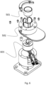
- Figures 5A and 5B illustrate what happens when the cartridge is inserted into a centrifuge instrument.
- Figs. 5A and 5B illustrate the cartridge before and after the pot has been disengaged from the second holding means 405.
- the centrifuge instrument may comprise a rotor 501 and first and second cartridge holding means 502 and 503 for securing the cartridge during centrifugation.
- the centrifuge instrument and cartridge may also comprise corresponding interfaces for allowing the centrifuge instrument to connect to the dispensing element 402 and aspirating element 403 of the cartridge.
- the centrifuge instrument may be part of an integrated diagnostic instrument for both centrifuging blood and analysing the obtained plasma.
- the rotor 501 may engage with the outer ribs 203 of the pot (if present) or may use friction with an outer surface of the pot to drive rotation of the pot during centrifugation.
- the centrifuge instrument may comprise a disengaging means 504 to provide the force to disengage the second holding means 405 from the pot (if the second holding means is present). Such a disengaging force may be transmitted through the top end 121 of the pot, as shown in Figs. 5A and 5B .
- This disengaging means 504 could be a passive extension which disengages the second holding means 405 from the pot when the first and second cartridge holding means 502 and 503 are secured around the cartridge.
- the disengaging means 504 could be an active linear actuator, controlled to disengage the pot from the second holding means 405 only when the centrifuge instrument is ready to perform centrifugation.
- the disengaging means 504 may only be used after the dispensing element 402 has filled the pot.
- the rotor 501 may be driven by a brushless DC motor 601.
- the holding means 502 may be part of the instrument housing, and may align the cartridge with the rotor 501 and ensure spacing between the cartridge and the spinning rotor, such that the cartridge cannot become misaligned during centrifugation or provide friction against the rotor 501.
- the pot has been shown to have scalloped baffles 114.
- these baffles may be omitted and the invention may instead rely on the protrusion 202.
- the baffles can take a variety of forms and can vary in their number.
- the baffles can protrude straight from the wall 111 toward the centre 201 and be of equal length and height, as shown in Figure 7 . In this example, there are six baffles.
- the number of radial baffles 114 can also be adapted depending on the properties of the liquid being centrifuged within the pot. In general, a pot with more radial baffles will help maintain separation better. For example, the pot of Figure 8 has 10 baffles. However, as the number of baffles increases, this will reduce the available volume of the pot as well as provide more points for liquid to become trapped, or 'pinned', due to surface tension.
- the baffles 114 may comprise a first baffle 114a that protrudes from the wall 111 by a first distance and a second baffle 114b that protrudes from the wall by a second distance, the first distance being different from the second distance.
- the baffles 114 may comprise plural of each type of baffle 114a, 114b, as shown in Figure 8 and Figure 9 . This arrangement enables more of the baffles to protrude further in toward the centre of the pot which helps to prevent remixing of the blood and plasma under deceleration without making the opening from the pot into the baffled zones too small, which might otherwise cause issues with surface tension pinning in pots with small dimensions.
- baffles act to provide more "separated" compartments whilst maintaining an minimum width of opening 901 between the baffles large that is enough to prevent pinning via surface tension. In many examples, this means that the baffles do not protrude as far as the centre 201, and protrude from the wall 111 by a distance less than a radius fo the pot.
- baffles 114a, 114b of different lengths are connected to the protrusion 202.
- the "compartments" defined by the baffles may be truly separated from the rest of the inner volume (in a plane perpendicular to the central axis 112) for at least part of the height of the pot, making remixing of cellular matter 301 and plasma 302 yet slower or even impossible.
- the shape of the baffles can also affect how the device performs.
- the shape of the baffles can be formed as an angled scallop which further helps to keep the blood and plasma separated, as shown in Fig. 1 .
- FIG. 11 Further detail of a particularly advantageous scalloped baffle embodiment is shown in Figure 11 .
- the scalloped baffles are formed as an arc of a curve of a radius 1101 between 0.25 and 0.35 of the radius of the pot, in a plane defined by the central axis 112 (as opposed to curving in a vertical plane).
- the scalloped baffles may be formed as an arc of a curve having a radius between 0.12 and 0.18 of a width of the pot.
- the scalloped baffles protrude into the inner volume by a distance of between 0.25 and 0.5 of the radius of the pot, as illustrated in Fig. 11 by the distance 1102 between the centre 201 and the and end of a baffle 114.
- the scalloped baffles may protrude into the inner volume by a distance of between 0.25 and 0.5 of the average half-width of the pot.
- baffle may be horizontal, or may curve in a vertical plane parallel to the central axis 112 towards or away from the bottom end 113 of the pot, as the baffle 114 protrudes away from the wall 111.
- baffles have been described by reference to Figs. 7 to 11 . More generally, various combinations of baffle number, baffle length(s), baffle shape and connectivity between baffles and the protrusion 202 are envisaged.
Landscapes
- Centrifugal Separators (AREA)
Claims (14)
- Consommable de type cassette comprenant :un pot pour la séparation par centrifugation d'un liquide biologique en de multiples composants (301, 302),un corps de cassette (401, 401') conçu pour recevoir le pot etun premier moyen de retenue (404) servant à maintenir le pot au moins en partie à l'intérieur du corps de cassette (401, 401'),où le premier moyen de retenue est conçu pour permettre une rotation du pot,le pot comprenant une paroi (111) autour d'un axe central (112), une face supérieure (121) et une face inférieure (113), le pot comprenant en outre :une pluralité de déflecteurs (114) faisant saillie depuis la paroi (111) jusqu'à un volume intérieur du pot et/ouune saillie (202) qui se prolonge depuis la face inférieure (113) jusqu'au volume intérieur et autour de l'axe central,le consommable de type cassette comprenant en outre un élément distributeur (402) conçu pour transférer un liquide biologique (301, 302) dans le pot et un élément aspirateur (403) conçu pour extraire un composant (302) du liquide biologique contenu dans le pot.
- Consommable de type cassette selon la revendication 1, où le pot est conçu pour être centrifugé sur l'axe central pour séparer par centrifugation le liquide biologique dans le volume intérieur, les multiples composants demeurant séparés quand le pot cesse de tourner.
- Consommable de type cassette selon l'une quelconque des revendications précédentes, où chacun des déflecteurs de la pluralité de déflecteurs (114) ne fait pas saillie jusqu'à un centre du pot et se prolonge le long de la paroi (111) sur entre la moitié et la totalité d'une distance entre la face supérieure et la face inférieure du pot.
- Consommable de type cassette selon l'une quelconque des revendications précédentes, où les déflecteurs de la pluralité de déflecteurs (114) sont espacés d'une distance sensiblement égale autour de l'axe central.
- Consommable de type cassette selon l'une quelconque des revendications précédentes, où la pluralité de déflecteurs (114) comprend un premier déflecteur (114a) qui fait saillie d'une première distance depuis la paroi et un second déflecteur (114b) qui fait saillie d'une seconde distance depuis la paroi, la première distance étant différente de la seconde distance.
- Consommable de type cassette selon l'une quelconque des revendications précédentes, où les déflecteurs de la pluralité de déflecteurs ont chacun la forme de l'arc d'une courbe dans un plan défini par l'axe central, la courbe ayant un rayon compris entre 0,12 et 0,18 fois une largeur du pot.
- Consommable de type cassette selon l'une quelconque des revendications précédentes, où la saillie (202) qui se prolonge depuis la face inférieure (113) est formée autour de l'axe central sur une largeur qui correspond approximativement à la moitié d'une largeur du pot et fait saillie d'entre 1 mm et 4 mm depuis la face inférieure.
- Consommable de type cassette selon l'une quelconque des revendications précédentes, où la séparation par centrifugation entraîne le plasma (302) vers l'axe central et où le pot est conçu pour permettre à un composant du liquide biologique d'être extrait au travers d'une ouverture (122) ménagée dans la face supérieure (121).
- Consommable de type cassette selon l'une quelconque des revendications précédentes, où une largeur du pot est inférieure à 40 mm.
- Consommable de type cassette selon l'une quelconque des revendications précédentes, où une distance entre la face supérieure (121) et la face inférieure (113) est inférieure à 30 mm.
- Consommable de type cassette selon l'une quelconque des revendications précédentes, où le pot est conçu pour être centrifugé à au moins 10 000 rpm.
- Consommable de type cassette selon l'une quelconque des revendications précédentes, où le liquide biologique est le sang et où les multiples composants du liquide biologique comprennent le plasma et les éléments cellulaires.
- Consommable de type cassette selon l'une quelconque des revendications précédentes comprenant en outre un second moyen de retenue (405) conçu pour maintenir le pot fermement en place jusqu'à l'insertion de la cassette dans un appareil de centrifugation et pour relâcher le pot afin qu'il puisse être centrifugé librement une fois la cassette insérée dans l'appareil de centrifugation.
- Consommable de type cassette selon l'une quelconque des revendications précédentes conçu pour maintenir le pot au moins en partie à l'intérieur du corps de cassette (401, 401') quand le pot est centrifugé à au moins 10 000 rpm.
Applications Claiming Priority (2)
| Application Number | Priority Date | Filing Date | Title |
|---|---|---|---|
| GB201913321A GB201913321D0 (en) | 2019-09-16 | 2019-09-16 | Disposable centrifuge pot |
| PCT/GB2020/052234 WO2021053329A1 (fr) | 2019-09-16 | 2020-09-16 | Pot jetable de centrifugeuse |
Publications (3)
| Publication Number | Publication Date |
|---|---|
| EP4031286A1 EP4031286A1 (fr) | 2022-07-27 |
| EP4031286B1 true EP4031286B1 (fr) | 2024-10-09 |
| EP4031286C0 EP4031286C0 (fr) | 2024-10-09 |
Family
ID=68315440
Family Applications (1)
| Application Number | Title | Priority Date | Filing Date |
|---|---|---|---|
| EP20780277.8A Active EP4031286B1 (fr) | 2019-09-16 | 2020-09-16 | Pot jetable de centrifugeuse |
Country Status (4)
| Country | Link |
|---|---|
| US (1) | US20220331818A1 (fr) |
| EP (1) | EP4031286B1 (fr) |
| GB (1) | GB201913321D0 (fr) |
| WO (1) | WO2021053329A1 (fr) |
Families Citing this family (1)
| Publication number | Priority date | Publication date | Assignee | Title |
|---|---|---|---|---|
| CN115025891B (zh) * | 2022-06-01 | 2025-09-12 | 深圳赛桥生物创新技术有限公司 | 一种离心杯、细胞离心方法及离心设备 |
Family Cites Families (10)
| Publication number | Priority date | Publication date | Assignee | Title |
|---|---|---|---|---|
| US1765386A (en) * | 1925-01-17 | 1930-06-24 | Nat Aniline & Chem Co Inc | Producing nonturbulent circulation of liquids |
| US2883103A (en) * | 1953-03-09 | 1959-04-21 | Technicon International Ltd | Centrifuge apparatus and method |
| EP0794835A1 (fr) * | 1995-10-03 | 1997-09-17 | Beckman Instruments, Inc. | Systeme et procede de separation du sang par rotation axiale |
| JP3619933B2 (ja) * | 2000-03-02 | 2005-02-16 | アークレイ株式会社 | 遠心分離用容器 |
| US6551230B2 (en) * | 2000-04-04 | 2003-04-22 | Fleetguard, Inc. | Molded spiral vane and linear component for a centrifuge |
| US6540653B2 (en) * | 2000-04-04 | 2003-04-01 | Fleetguard, Inc. | Unitary spiral vane centrifuge module |
| US8043562B2 (en) * | 2003-12-08 | 2011-10-25 | Ortho-Clinical Diagnostics, Inc. | Analyzer having removable holders or a centrifuge |
| US8870733B2 (en) * | 2010-11-19 | 2014-10-28 | Kensey Nash Corporation | Centrifuge |
| JP5936576B2 (ja) * | 2013-03-29 | 2016-06-22 | 富士フイルム株式会社 | 遠心分離用容器および遠心分離装置並びにそれらを用いた遠心分離方法 |
| EP2842633A1 (fr) * | 2013-08-25 | 2015-03-04 | Molecular Devices, LLC | Appareil et procédé permettant de séparer des matériaux de différentes densités |
-
2019
- 2019-09-16 GB GB201913321A patent/GB201913321D0/en not_active Ceased
-
2020
- 2020-09-16 WO PCT/GB2020/052234 patent/WO2021053329A1/fr not_active Ceased
- 2020-09-16 EP EP20780277.8A patent/EP4031286B1/fr active Active
- 2020-09-16 US US17/760,616 patent/US20220331818A1/en active Pending
Also Published As
| Publication number | Publication date |
|---|---|
| US20220331818A1 (en) | 2022-10-20 |
| WO2021053329A1 (fr) | 2021-03-25 |
| EP4031286C0 (fr) | 2024-10-09 |
| GB201913321D0 (en) | 2019-10-30 |
| EP4031286A1 (fr) | 2022-07-27 |
Similar Documents
| Publication | Publication Date | Title |
|---|---|---|
| US5354483A (en) | Double-ended tube for separating phases of blood | |
| KR101495563B1 (ko) | 액체 분량을 소분량으로 나누는 미세유체 테스트 캐리어 | |
| CA1296693C (fr) | Appareil et methode de separation des phrases | |
| CN109982731B (zh) | 离心流体分离设备 | |
| US7371330B2 (en) | Particle sedimentation apparatus and method for performing particle sedimentation | |
| EP2511011A2 (fr) | Tube pour centrifugeuse | |
| US20170120259A1 (en) | Device for constant-volume collection using centrifugation or for further storage | |
| JPH04227080A (ja) | 特に全血から血漿を分離するのに適している不均一液体試料の2つの相を遠心分離によって分離する装置 | |
| AU615292B2 (en) | Apparatus for separating phases of blood | |
| US9610590B2 (en) | Centrifugal separating assembly with a container body having a common inlet-outlet port | |
| AU2016247157A1 (en) | Systems, methods, and apparatuses for performing automated reagent-based assays | |
| HUT77810A (hu) | Berendezés és eljárás, valamint centrifuga-reagens ellátó redszer egy komponens elválasztására plazmából | |
| KR101495631B1 (ko) | 원심분리 키트 및 이를 이용한 원심분리 방법 | |
| EP2928607B1 (fr) | Système de soupapes destiné à être utilisé dans des plateformes micro-fluidiques centrifuges | |
| KR20140125387A (ko) | 샘플 캐리어 원심분리기 | |
| JP5442699B2 (ja) | 血液サンプルの液状成分を分離する装置および方法、ならびにそのような装置を備える分析装置 | |
| JP3619933B2 (ja) | 遠心分離用容器 | |
| US4981654A (en) | Unitary centrifuge tube and separable dispensing receptacle | |
| US20220331818A1 (en) | Disposable Centrifuge Pot | |
| JP2014198281A (ja) | 遠心分離用容器および遠心分離装置並びにそれらを用いた遠心分離方法 | |
| KR102508907B1 (ko) | 원심 분리 장치용 챔버 및 이를 포함하는 원심 분리 장치 | |
| WO2009123447A1 (fr) | Dispositif de centrifugeuse permettant la collecte et la séparation du sang | |
| JP7733073B2 (ja) | 分離インサート、及び分離器具 | |
| JP6352862B2 (ja) | 比重分離層吸引/採取用チップ | |
| CA1338468C (fr) | Separateurs pour composants du sang |
Legal Events
| Date | Code | Title | Description |
|---|---|---|---|
| STAA | Information on the status of an ep patent application or granted ep patent |
Free format text: STATUS: UNKNOWN |
|
| STAA | Information on the status of an ep patent application or granted ep patent |
Free format text: STATUS: THE INTERNATIONAL PUBLICATION HAS BEEN MADE |
|
| PUAI | Public reference made under article 153(3) epc to a published international application that has entered the european phase |
Free format text: ORIGINAL CODE: 0009012 |
|
| STAA | Information on the status of an ep patent application or granted ep patent |
Free format text: STATUS: REQUEST FOR EXAMINATION WAS MADE |
|
| 17P | Request for examination filed |
Effective date: 20220316 |
|
| AK | Designated contracting states |
Kind code of ref document: A1 Designated state(s): AL AT BE BG CH CY CZ DE DK EE ES FI FR GB GR HR HU IE IS IT LI LT LU LV MC MK MT NL NO PL PT RO RS SE SI SK SM TR |
|
| DAV | Request for validation of the european patent (deleted) | ||
| DAX | Request for extension of the european patent (deleted) | ||
| GRAP | Despatch of communication of intention to grant a patent |
Free format text: ORIGINAL CODE: EPIDOSNIGR1 |
|
| STAA | Information on the status of an ep patent application or granted ep patent |
Free format text: STATUS: GRANT OF PATENT IS INTENDED |
|
| INTG | Intention to grant announced |
Effective date: 20240510 |
|
| RIN1 | Information on inventor provided before grant (corrected) |
Inventor name: MALLOY, ANDREW |
|
| RIN1 | Information on inventor provided before grant (corrected) |
Inventor name: MALLOY, ANDREW |
|
| RIN1 | Information on inventor provided before grant (corrected) |
Inventor name: MALLOY, ANDREW |
|
| GRAS | Grant fee paid |
Free format text: ORIGINAL CODE: EPIDOSNIGR3 |
|
| GRAA | (expected) grant |
Free format text: ORIGINAL CODE: 0009210 |
|
| STAA | Information on the status of an ep patent application or granted ep patent |
Free format text: STATUS: THE PATENT HAS BEEN GRANTED |
|
| AK | Designated contracting states |
Kind code of ref document: B1 Designated state(s): AL AT BE BG CH CY CZ DE DK EE ES FI FR GB GR HR HU IE IS IT LI LT LU LV MC MK MT NL NO PL PT RO RS SE SI SK SM TR |
|
| REG | Reference to a national code |
Ref country code: CH Ref legal event code: EP |
|
| REG | Reference to a national code |
Ref country code: DE Ref legal event code: R096 Ref document number: 602020039177 Country of ref document: DE |
|
| REG | Reference to a national code |
Ref country code: IE Ref legal event code: FG4D |
|
| U01 | Request for unitary effect filed |
Effective date: 20241022 |
|
| U07 | Unitary effect registered |
Designated state(s): AT BE BG DE DK EE FI FR IT LT LU LV MT NL PT RO SE SI Effective date: 20241106 |
|
| PG25 | Lapsed in a contracting state [announced via postgrant information from national office to epo] |
Ref country code: HR Free format text: LAPSE BECAUSE OF FAILURE TO SUBMIT A TRANSLATION OF THE DESCRIPTION OR TO PAY THE FEE WITHIN THE PRESCRIBED TIME-LIMIT Effective date: 20241009 Ref country code: IS Free format text: LAPSE BECAUSE OF FAILURE TO SUBMIT A TRANSLATION OF THE DESCRIPTION OR TO PAY THE FEE WITHIN THE PRESCRIBED TIME-LIMIT Effective date: 20250209 |
|
| PG25 | Lapsed in a contracting state [announced via postgrant information from national office to epo] |
Ref country code: ES Free format text: LAPSE BECAUSE OF FAILURE TO SUBMIT A TRANSLATION OF THE DESCRIPTION OR TO PAY THE FEE WITHIN THE PRESCRIBED TIME-LIMIT Effective date: 20241009 |
|
| PG25 | Lapsed in a contracting state [announced via postgrant information from national office to epo] |
Ref country code: NO Free format text: LAPSE BECAUSE OF FAILURE TO SUBMIT A TRANSLATION OF THE DESCRIPTION OR TO PAY THE FEE WITHIN THE PRESCRIBED TIME-LIMIT Effective date: 20250109 |
|
| PG25 | Lapsed in a contracting state [announced via postgrant information from national office to epo] |
Ref country code: GR Free format text: LAPSE BECAUSE OF FAILURE TO SUBMIT A TRANSLATION OF THE DESCRIPTION OR TO PAY THE FEE WITHIN THE PRESCRIBED TIME-LIMIT Effective date: 20250110 |
|
| PG25 | Lapsed in a contracting state [announced via postgrant information from national office to epo] |
Ref country code: PL Free format text: LAPSE BECAUSE OF FAILURE TO SUBMIT A TRANSLATION OF THE DESCRIPTION OR TO PAY THE FEE WITHIN THE PRESCRIBED TIME-LIMIT Effective date: 20241009 |
|
| PG25 | Lapsed in a contracting state [announced via postgrant information from national office to epo] |
Ref country code: RS Free format text: LAPSE BECAUSE OF FAILURE TO SUBMIT A TRANSLATION OF THE DESCRIPTION OR TO PAY THE FEE WITHIN THE PRESCRIBED TIME-LIMIT Effective date: 20250109 |
|
| PG25 | Lapsed in a contracting state [announced via postgrant information from national office to epo] |
Ref country code: SM Free format text: LAPSE BECAUSE OF FAILURE TO SUBMIT A TRANSLATION OF THE DESCRIPTION OR TO PAY THE FEE WITHIN THE PRESCRIBED TIME-LIMIT Effective date: 20241009 |
|
| PG25 | Lapsed in a contracting state [announced via postgrant information from national office to epo] |
Ref country code: SK Free format text: LAPSE BECAUSE OF FAILURE TO SUBMIT A TRANSLATION OF THE DESCRIPTION OR TO PAY THE FEE WITHIN THE PRESCRIBED TIME-LIMIT Effective date: 20241009 |
|
| PG25 | Lapsed in a contracting state [announced via postgrant information from national office to epo] |
Ref country code: CZ Free format text: LAPSE BECAUSE OF FAILURE TO SUBMIT A TRANSLATION OF THE DESCRIPTION OR TO PAY THE FEE WITHIN THE PRESCRIBED TIME-LIMIT Effective date: 20241009 |
|
| PLBE | No opposition filed within time limit |
Free format text: ORIGINAL CODE: 0009261 |
|
| STAA | Information on the status of an ep patent application or granted ep patent |
Free format text: STATUS: NO OPPOSITION FILED WITHIN TIME LIMIT |
|
| U20 | Renewal fee for the european patent with unitary effect paid |
Year of fee payment: 6 Effective date: 20250807 |
|
| 26N | No opposition filed |
Effective date: 20250710 |
|
| PGFP | Annual fee paid to national office [announced via postgrant information from national office to epo] |
Ref country code: GB Payment date: 20250703 Year of fee payment: 6 |
|
| PGFP | Annual fee paid to national office [announced via postgrant information from national office to epo] |
Ref country code: IE Payment date: 20251202 Year of fee payment: 6 |
|
| REG | Reference to a national code |
Ref country code: CH Ref legal event code: H13 Free format text: ST27 STATUS EVENT CODE: U-0-0-H10-H13 (AS PROVIDED BY THE NATIONAL OFFICE) Effective date: 20260504 |
|
| PG25 | Lapsed in a contracting state [announced via postgrant information from national office to epo] |
Ref country code: MC Free format text: LAPSE BECAUSE OF FAILURE TO SUBMIT A TRANSLATION OF THE DESCRIPTION OR TO PAY THE FEE WITHIN THE PRESCRIBED TIME-LIMIT Effective date: 20241009 |
|
| PG25 | Lapsed in a contracting state [announced via postgrant information from national office to epo] |
Ref country code: CH Free format text: LAPSE BECAUSE OF NON-PAYMENT OF DUE FEES Effective date: 20250930 |