EP4031313B1 - Machine-outil pour usiner des dents, procédé d'usinage de flancs de dents d'une pièce à usiner et procédé de dressage d'un outil d'usinage de dents à l'aide d'une telle machine-outil - Google Patents
Machine-outil pour usiner des dents, procédé d'usinage de flancs de dents d'une pièce à usiner et procédé de dressage d'un outil d'usinage de dents à l'aide d'une telle machine-outil Download PDFInfo
- Publication number
- EP4031313B1 EP4031313B1 EP20764428.7A EP20764428A EP4031313B1 EP 4031313 B1 EP4031313 B1 EP 4031313B1 EP 20764428 A EP20764428 A EP 20764428A EP 4031313 B1 EP4031313 B1 EP 4031313B1
- Authority
- EP
- European Patent Office
- Prior art keywords
- tool
- workpiece
- spindle
- along
- axis
- Prior art date
- Legal status (The legal status is an assumption and is not a legal conclusion. Google has not performed a legal analysis and makes no representation as to the accuracy of the status listed.)
- Active
Links
Images



Classifications
-
- B—PERFORMING OPERATIONS; TRANSPORTING
- B23—MACHINE TOOLS; METAL-WORKING NOT OTHERWISE PROVIDED FOR
- B23F—MAKING GEARS OR TOOTHED RACKS
- B23F23/00—Accessories or equipment combined with or arranged in, or specially designed to form part of, gear-cutting machines
- B23F23/10—Arrangements for compensating irregularities in drives or indexing mechanisms
-
- B—PERFORMING OPERATIONS; TRANSPORTING
- B23—MACHINE TOOLS; METAL-WORKING NOT OTHERWISE PROVIDED FOR
- B23F—MAKING GEARS OR TOOTHED RACKS
- B23F5/00—Making straight gear teeth involving moving a tool relatively to a workpiece with a rolling-off or an enveloping motion with respect to the gear teeth to be made
-
- B—PERFORMING OPERATIONS; TRANSPORTING
- B23—MACHINE TOOLS; METAL-WORKING NOT OTHERWISE PROVIDED FOR
- B23F—MAKING GEARS OR TOOTHED RACKS
- B23F1/00—Making gear teeth by tools of which the profile matches the profile of the required surface
- B23F1/02—Making gear teeth by tools of which the profile matches the profile of the required surface by grinding
- B23F1/023—Making gear teeth by tools of which the profile matches the profile of the required surface by grinding the tool being a grinding worm
-
- B—PERFORMING OPERATIONS; TRANSPORTING
- B23—MACHINE TOOLS; METAL-WORKING NOT OTHERWISE PROVIDED FOR
- B23F—MAKING GEARS OR TOOTHED RACKS
- B23F15/00—Methods or machines for making gear wheels of special kinds not covered by groups B23F7/00 - B23F13/00
-
- B—PERFORMING OPERATIONS; TRANSPORTING
- B23—MACHINE TOOLS; METAL-WORKING NOT OTHERWISE PROVIDED FOR
- B23F—MAKING GEARS OR TOOTHED RACKS
- B23F19/00—Finishing gear teeth by other tools than those used for manufacturing gear teeth
- B23F19/002—Modifying the theoretical tooth flank form, e.g. crowning
-
- B—PERFORMING OPERATIONS; TRANSPORTING
- B23—MACHINE TOOLS; METAL-WORKING NOT OTHERWISE PROVIDED FOR
- B23F—MAKING GEARS OR TOOTHED RACKS
- B23F23/00—Accessories or equipment combined with or arranged in, or specially designed to form part of, gear-cutting machines
-
- B—PERFORMING OPERATIONS; TRANSPORTING
- B23—MACHINE TOOLS; METAL-WORKING NOT OTHERWISE PROVIDED FOR
- B23F—MAKING GEARS OR TOOTHED RACKS
- B23F23/00—Accessories or equipment combined with or arranged in, or specially designed to form part of, gear-cutting machines
- B23F23/006—Equipment for synchronising movement of cutting tool and workpiece, the cutting tool and workpiece not being mechanically coupled
-
- B—PERFORMING OPERATIONS; TRANSPORTING
- B23—MACHINE TOOLS; METAL-WORKING NOT OTHERWISE PROVIDED FOR
- B23F—MAKING GEARS OR TOOTHED RACKS
- B23F5/00—Making straight gear teeth involving moving a tool relatively to a workpiece with a rolling-off or an enveloping motion with respect to the gear teeth to be made
- B23F5/02—Making straight gear teeth involving moving a tool relatively to a workpiece with a rolling-off or an enveloping motion with respect to the gear teeth to be made by grinding
- B23F5/04—Making straight gear teeth involving moving a tool relatively to a workpiece with a rolling-off or an enveloping motion with respect to the gear teeth to be made by grinding the tool being a grinding worm
-
- B—PERFORMING OPERATIONS; TRANSPORTING
- B23—MACHINE TOOLS; METAL-WORKING NOT OTHERWISE PROVIDED FOR
- B23F—MAKING GEARS OR TOOTHED RACKS
- B23F9/00—Making gears having teeth curved in their longitudinal direction
- B23F9/02—Making gears having teeth curved in their longitudinal direction by grinding
-
- B—PERFORMING OPERATIONS; TRANSPORTING
- B23—MACHINE TOOLS; METAL-WORKING NOT OTHERWISE PROVIDED FOR
- B23Q—DETAILS, COMPONENTS, OR ACCESSORIES FOR MACHINE TOOLS, e.g. ARRANGEMENTS FOR COPYING OR CONTROLLING; MACHINE TOOLS IN GENERAL CHARACTERISED BY THE CONSTRUCTION OF PARTICULAR DETAILS OR COMPONENTS; COMBINATIONS OR ASSOCIATIONS OF METAL-WORKING MACHINES, NOT DIRECTED TO A PARTICULAR RESULT
- B23Q1/00—Members which are comprised in the general build-up of a form of machine, particularly relatively large fixed members
- B23Q1/70—Stationary or movable members for carrying working-spindles for attachment of tools or work
- B23Q1/706—Movable members, e.g. swinging arms
-
- B—PERFORMING OPERATIONS; TRANSPORTING
- B23—MACHINE TOOLS; METAL-WORKING NOT OTHERWISE PROVIDED FOR
- B23Q—DETAILS, COMPONENTS, OR ACCESSORIES FOR MACHINE TOOLS, e.g. ARRANGEMENTS FOR COPYING OR CONTROLLING; MACHINE TOOLS IN GENERAL CHARACTERISED BY THE CONSTRUCTION OF PARTICULAR DETAILS OR COMPONENTS; COMBINATIONS OR ASSOCIATIONS OF METAL-WORKING MACHINES, NOT DIRECTED TO A PARTICULAR RESULT
- B23Q5/00—Driving or feeding mechanisms; Control arrangements therefor
- B23Q5/22—Feeding members carrying tools or work
- B23Q5/34—Feeding other members supporting tools or work, e.g. saddles, tool-slides, through mechanical transmission
-
- B—PERFORMING OPERATIONS; TRANSPORTING
- B24—GRINDING; POLISHING
- B24B—MACHINES, DEVICES, OR PROCESSES FOR GRINDING OR POLISHING; DRESSING OR CONDITIONING OF ABRADING SURFACES; FEEDING OF GRINDING, POLISHING, OR LAPPING AGENTS
- B24B53/00—Devices or means for dressing or conditioning abrasive surfaces
- B24B53/005—Positioning devices for conditioning tools
-
- G—PHYSICS
- G05—CONTROLLING; REGULATING
- G05B—CONTROL OR REGULATING SYSTEMS IN GENERAL; FUNCTIONAL ELEMENTS OF SUCH SYSTEMS; MONITORING OR TESTING ARRANGEMENTS FOR SUCH SYSTEMS OR ELEMENTS
- G05B19/00—Program-control systems
- G05B19/02—Program-control systems electric
- G05B19/18—Numerical control [NC], i.e. automatically operating machines, in particular machine tools, e.g. in a manufacturing environment, so as to execute positioning, movement or co-ordinated operations by means of program data in numerical form
- G05B19/19—Numerical control [NC], i.e. automatically operating machines, in particular machine tools, e.g. in a manufacturing environment, so as to execute positioning, movement or co-ordinated operations by means of program data in numerical form characterised by positioning or contouring control systems, e.g. to control position from one programmed point to another or to control movement along a programmed continuous path
Definitions
- the present invention relates to a machine tool according to the preamble of claim 1 for machining gears, methods for its operation, and a computer program for carrying out the methods.
- the machining forces may be relatively small. This can lead to a load change when reversing the direction along the radial infeed direction, which leads to an additional undesirable reversal effect due to the finite stiffness of the components involved.
- DE 10 2012 016515 A1 discloses a machine tool according to the preamble of claim 1, namely a gear shaping machine whose shaping head slide is mounted on a machine stand in an inclined position. In this way, a displacement in the vertical direction results in a simultaneous displacement of the shaping tool in the horizontal direction in order to lift the shaping tool from the workpiece during the return stroke. The production of modifications is not addressed.
- the axial slide is guided along an axial guide direction that is inclined relative to the workpiece axis at an angle of inclination.
- the angle of inclination has a value between 0.1° and 30°, preferably between 0.1° and 15°, and particularly preferably between 0.1° and 3°. In some embodiments, the angle of inclination has a value between 0.5° and 30°, between 0.5° and 15°, or between 0.5° and 3°.
- the axial slide carries either the workpiece spindle or the tool spindle. Due to the inclined guide of the axial slide, the radial distance between the tool axis and the workpiece axis changes when the The axial slide is positioned along the axial guide direction. This makes it possible to machine gears with tooth trace modifications without having to reverse the direction of the radial feed movement during gear machining. The problems mentioned above that arise from a reversal of direction are thus avoided. Furthermore, it is possible to machine even the smallest tooth trace modifications without causing disruptive friction effects.
- the machine tool also features an infeed slide, which allows the center distance between the tool axis and the workpiece axis to be further varied along an infeed direction.
- This infeed can occur independently of the movement along the axial guide direction. It is superimposed on the change in the center distance due to the inclined guide of the axial slide. Accordingly, during the machining of the tooth flanks, the axial slide and the infeed slide move simultaneously.
- the feed direction can, but does not have to, be perpendicular to the workpiece axis. It is referred to below as the "radial feed direction," even though this direction is not necessarily exactly radial to the workpiece axis, i.e., not necessarily exactly perpendicular to the workpiece axis.
- the radial feed direction can form an angle with the workpiece axis in the range of 60° to 120°.
- the axial guide direction preferably runs in a common plane with the workpiece axis and the radial feed direction.
- the inclination angle can be positive or negative in this plane, i.e., the axial guide direction can be inclined away from or toward the workpiece axis (as viewed from the machine bed).
- the tool spindle is mounted directly or indirectly (i.e., via additional slides and/or swivel bodies) on the axial slide, meaning the tool spindle executes movements along the inclined axial guide direction relative to a machine bed of the machine tool.
- the axial slide forms a tool carrier.
- the workpiece spindle it is also conceivable for the workpiece spindle to be mounted directly or indirectly on the axial slide, meaning that the workpiece spindle executes movements along the inclined axial guide direction relative to the machine bed.
- the feed slide can be guided on the machine bed so as to be displaceable along the radial feed direction and form a tool carrier, and the axial slide can then be arranged on the feed slide so as to be guided along the axial guide direction.
- the tool spindle can be pivoted about a pivot axis relative to the axial slide.
- the machine tool can have a pivot body.
- the pivot body can in particular be arranged on the axial slide. If the tool is a grinding tool, the pivot body is also referred to as a grinding head.
- the pivot axis preferably runs parallel to the radial feed direction or perpendicular to the workpiece axis. However, it can also run at an angle to the radial feed direction that deviates from 0°, with this angle preferably lying between 0° and 30°.
- the pivot axis can also run at an angle to the workpiece axis that deviates from 90°, with this angle preferably lying in the range of 60° to 120°.
- the pivot axis can run perpendicular to the axial guide direction. It is advantageous if the pivot axis lies in a plane spanned by the workpiece axis and the axial guide direction.
- the tool spindle is displaceable relative to the axial slide along a shift direction that runs parallel to the tool axis.
- the machine tool may have a shift slide.
- the shift slide may, in particular, be mounted on the pivoting body such that it is displaceable relative to the pivoting body along the shift direction.
- the shift direction preferably runs perpendicular to the pivot axis about which the tool spindle is pivotable. In some embodiments, it also runs perpendicular to the radial feed direction.
- the machine has a control device which is designed to control the machine tool in such a way that it carries out corresponding simultaneous movements between the tool spindle and the workpiece spindle along the inclined axial guide direction and the radial feed direction.
- the sign of the axial guide speed does not change during a machining stroke.
- the sign of the radial infeed speed also preferably does not change during a machining stroke.
- the radial infeed speed during a machining stroke does not fall below a predetermined threshold value. This avoids adverse effects during the radial infeed movement. As a result, tooth trace modifications can be manufactured with much greater precision than with the prior art.
- the radial infeed speed and the axial guide speed are in a temporally variable relationship.
- these speeds can be in a variable relationship such that the radial infeed speed does not change its sign during a machining stroke (and thus during the machining of a tooth flank), while a resulting movement between the tool spindle and the workpiece spindle along the radial infeed direction has a speed that changes its sign during the machining of the tooth flanks (or during a machining stroke).
- This allows, in particular, wide-crowned modified gears to be manufactured without the above-described disadvantages of the prior art.
- the machine tool can have a dressing device with a dressing tool.
- the control device can then be designed to dress the tool, in particular a grinding worm, with the dressing tool, generating Dressing movements along the inclined axial guide direction.
- dressing relative movements are generated between the tool and the dressing tool along the inclined axial guide direction while the tool is in engagement with the dressing tool. This allows dressing to achieve similar benefits to those achieved when machining gears.
- the control device can be designed to align the tool spindle with its pivot axis relative to the axial slide such that the tool axis runs in or parallel to a plane spanned by the axial guide direction and the radial feed direction.
- This position of the tool spindle is referred to below as the dressing position.
- the specified selection of the dressing position is particularly advantageous when the tool is a grinding worm.
- the grinding worm can thus be easily moved along its longitudinal axis, i.e., along the tool axis, along the inclined axial guide direction relative to the dressing tool in order to dress the grinding worm across its entire width.
- the axial slide can be used for this purpose. If the tool spindle is mounted on a shift slide, the shift slide can also be used alternatively or additionally, depending on the design.
- the dressing device can have a dressing spindle designed to drive the dressing tool to rotate about a dressing spindle axis.
- the dressing spindle is preferably pivotable about at least one pivot axis in order to bring the dressing tool into engagement with the machining tool when the tool spindle is in the dressing position specified above.
- the dressing device can have a corresponding pivot body.
- the pivot axis of the dressing spindle preferably runs transversely to the axial feed direction, in particular at an angle of 60° to 120° to the axial feed direction, and transversely to the workpiece axis, preferably at an angle of 60° to 120° to the workpiece axis, in particular perpendicular to the latter. If the workpiece axis runs vertically in space, the pivot axis of the dressing spindle preferably runs horizontally.
- the grinding head 9 in turn, carries a shift slide, on which a tool spindle 11 can be shifted along a shift direction Y.
- the shift direction Y runs perpendicular to the pivot axis A and thus also perpendicular to the X direction, but not necessarily perpendicular to the Z' direction.
- a finishing tool in the form of a helically profiled grinding wheel (grinding worm) 12 is clamped on the tool spindle 11.
- the grinding worm 12 is driven by the tool spindle 11 to rotate about a tool axis B.
- the tool axis B runs parallel to the Y-direction.
- the workpiece 19 is clamped by an automatic workpiece changer onto the workpiece spindle 17 located in the workpiece change position.
- the workpiece change takes place in parallel with the machining of another workpiece 18 on the other workpiece spindle 16, which is in the machining position.
- the workpiece carrier 15 is pivoted 180° about the C3 axis so that the spindle with the newly machined workpiece moves into the machining position.
- a centering operation is performed using a centering probe (not shown in the drawing) arranged on the workpiece carrier 15.
- the workpiece spindle 17 is rotated, and the position of the tooth gaps of the workpiece 19 is measured using the centering probe.
- the rolling angle is determined on this basis.
- the workpiece spindle 17, which carries the workpiece 19 to be machined has reached the machining position, the workpiece 19 is brought into engagement with the grinding worm 12 by moving the tool carrier 5 along the X-axis. The workpiece 19 is then machined by the rotating grinding worm 12 in rolling engagement.
- the machine executes coordinated movements along the X, Y, and Z axes. Machining can be performed in one or more axial machining strokes. During each machining stroke, the machine executes a movement along the Z' axis, the speed of which does not change its sign.
- a further direction, Z is defined.
- this runs parallel to the workpiece axis C1, i.e., the rotational axis of the workpiece in the machining position.
- the machining stroke along the Z' axis continuously changes the position of the tool relative to the workpiece along the Z direction in order to machine the gear teeth across the entire width of the workpiece.
- This is referred to as the axial feed, and the Z direction is therefore also referred to as the axial feed direction.
- the machine control normally calculates the corresponding control commands in the X, Y, Z coordinate system for a desired flank shape of the gear.
- a pure feed movement along the Z-direction requires Simultaneous movements along the X and Z directions.
- the machine control is advantageously designed to transform the usual feed commands for movements along the Z direction into transformed control commands for simultaneous movements along the X and Z directions.
- the inverse transformation T -1 is used when measurements are taken with a measuring system arranged along the X and Z' directions, and the X and Z coordinates of the axial slide 7 are to be determined based on such measurements.
- This inverse transformation may be necessary to transfer the measured coordinates to the machine control in the required form.
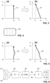
- a wide crowned modified spur gear 32 is symbolically shown in the Fig. 4
- the teeth of the spur gear are thicker in the middle than at the ends along the width direction (during machining this is the Z-direction), and the tooth flanks are curved accordingly.
- the tip diameter in the center of the spur gear is larger than at the edges, so that the spur gear also receives a barrel-shaped outer contour.
- Fig. 4 The barrel-shaped outer contour is drawn extremely exaggerated to simplify the explanation of the principle. In reality, such modifications usually only vary in size by a few micrometers and are invisible to the naked eye.
- the Figure 6 schematically illustrates various functional units that are used to generate the axial feed movement along the Z direction and the radial infeed movement along the X direction.
- Position sensors 41, 42 detect the positions x', z' of the axial slide 7 along the X and Z directions.
- a first transformation device 43 transforms these positions in the X, Y, Z' coordinate system into the positions x and z in the X, Y, Z coordinate system by applying the inverse transformation T -1 and transfers these actual values to a control computer 44 of the machine control system.
- the control computer 44 generates control signals Ax, Az that correspond to setpoints for the positions of the axial slide 7 in the X, Y, Z coordinate system.
- a second transformation device 45 transforms these control signals into transformed control signals Ax', Az' in the X, Y, Z' coordinate system and transfers these transformed control signals to the axis modules 3 of the machine control system.
- the dressing device 13 is mounted on the workpiece carrier (rotating turret) 15. It can be brought into a position in which it faces the grinding worm 12 by pivoting the turret through 90°.
- the dressing device 13 comprises a dressing spindle with a dressing wheel 14 mounted thereon, which is driven to rotate.
- the dressing spindle is mounted on a pivoting body 21. This is pivotally connected to the workpiece carrier in such a way that the dressing wheel 14 can be rotated in the direction of the worm threads and relative to the grinding worm profile.
- the corresponding swivel axis runs perpendicular to the workpiece axes C1, C2 and horizontally in space.
- the corresponding swivel axis runs perpendicular to the drawing plane.
- the dressing spindle can be swiveled about another swivel axis, which also runs horizontally in space and is perpendicular to the aforementioned swivel axis.
- This additional swivel axis runs horizontally in the drawing plane. This additional swivel axis can be used, for example, to change the profile angle during dressing.
- the present invention is also advantageous when dressing is carried out with a gear-shaped dressing wheel clamped on the workpiece spindle.
- the advantages of the present invention were explained above using the example of the production of wide-crowned modified spur gears.
- the invention is not limited to this application, but can also be advantageously used in the production of other gears or gears.
- the invention also has advantages in the production of gears modified in other ways, e.g., conically modified gears, since disruptive friction effects can be avoided with the invention in these cases as well.
- FIG. 7 A second embodiment of a generating grinding machine is shown schematically. This differs from the first embodiment in that the A-axis is not perpendicular to the Z-direction and parallel to the X-direction, but perpendicular to the Z'-direction and accordingly at an angle ⁇ to the X-direction. As a result, the Y-axis and the tool axis B are no longer perpendicular to the X-direction as soon as the swivel angle around the A-axis differs from the Fig. 7 shown position. Nevertheless, the advantages mentioned above can still be achieved with this arrangement. This design is particularly suitable for small inclination angles between 0.1° and 3°.
- FIG. 8 A third embodiment of a generating grinding machine is shown schematically.
- the entire tool carrier 5, including the axial slide 7, shift slide, and grinding head 9, is of conventional construction.
- the axial guide direction Z' runs perpendicular to the feed direction X.
- the workpiece carrier (rotating turret) 15 is inclined relative to the vertical.
- the workpiece axis C1 and thus also the axial feed direction Z which by definition runs parallel to the workpiece axis C1, no longer runs perpendicular to the X direction.
- this embodiment also requires additional coordinate transformations to convert from a coordinate system defined by the machine axes X, Y, Z', A, B, C1 to an orthogonal coordinate system or to a conventional coordinate system of the machine control system, and vice versa.
- the corresponding transformations can again be easily derived using simple trigonometric considerations.
- FIG. 9 A generating grinding machine according to a fourth embodiment is shown schematically.
- the turret with the axes C1 and C3 is positioned vertically in space, and the axial slide 7 is guided relative to the tool carrier 5 along an axial guide direction Z', which runs at an inclination angle ⁇ to the vertical relative to the workpiece axis C1 running vertically in space.
- the entire tool carrier 5, including the axial slide 7, shift slide, and grinding head 9 is not guided exactly horizontally on the machine bed 4, but along a direction that runs at an inclination angle ⁇ to the horizontal.
- this guide direction is again referred to as the X direction.
- the X direction is therefore not perpendicular to the Z direction here, but perpendicular to the Z' direction.
- the A axis runs horizontally in space and thus perpendicular to the Z direction.
- the A-axis does not run parallel to the X-direction.
- this embodiment also requires additional coordinate transformations to convert from a coordinate system defined by the machine axes X, Y, Z', A, B, C1 to an orthogonal coordinate system or to a conventional coordinate system of the machine control system, and vice versa.
- the corresponding transformations can again be easily derived using simple trigonometric considerations.
- the inclination angle ⁇ is positive, i.e. the Z' axis is inclined towards the positive X direction or away from the workpiece axis C1.
- a negative inclination angle ⁇ can be particularly advantageous if the final finishing stroke is along the negative Z-direction (i.e. in the Figure 2 from top to bottom), since the tool carrier 5 is then moved along the negative X direction, i.e., toward the workpiece, to generate the compensation movement. This is advantageous because the radial machining forces counteract the compensation movement, resulting in defined force ratios in the components involved in generating the X movement.
- the present invention is not limited to a specific machining method.
- the advantages of the invention were explained above with reference to continuous generating grinding.
- the invention also demonstrates its advantages in other processes for producing gears, including processes with a geometrically undefined cutting edge and processes with a geometrically defined cutting edge. Examples include pitch generating grinding, discontinuous or continuous profile grinding, gear honing, gear hobbing, or gear skiving.
- the invention can be used to manufacture both externally and internally toothed workpieces.
- the invention is particularly advantageously used in the fine machining of pre-toothed workpieces, in particular in hard fine machining.
- the present invention is not limited to a specific axis sequence. Depending on the type of machine, it may also be advantageous, for example, to arrange the axial slide directly on the machine bed and mount the workpiece spindle on a radial slide in order to achieve radial feed through movement of the workpiece spindle.
- the present invention is also not limited to the radial feed direction X running perpendicular to the workpiece axis C1.
- the radial feed direction X runs at an angle other than 90° to the workpiece axis C1.
- the axial guide direction Z' runs in a common plane with the radial feed direction X and the workpiece axis C1.
- the at least one workpiece spindle does not need to be mounted on a movable workpiece carrier, but can be mounted directly on the The machine bed can be arranged.
- the at least one workpiece spindle is arranged on a movable workpiece carrier, which implements the radial feed movement along the X-direction.
- the A-axis can also be implemented on the workpiece side instead of the tool side.
- the dressing device 13 can also be attached to the machine bed instead of to a movable workpiece carrier.
- the tool carrier 5 can be pivoted relative to the machine bed in order to move the machining tool to the dressing tool, as is shown, for example, in US5857894B is known.
- the present invention is not limited to specific drive types for the various linear guides.
- the drive can be implemented in any manner known in the art, e.g., by ball screws or linear motors.
Landscapes
- Engineering & Computer Science (AREA)
- Mechanical Engineering (AREA)
- Automation & Control Theory (AREA)
- Manufacturing & Machinery (AREA)
- Physics & Mathematics (AREA)
- General Physics & Mathematics (AREA)
- Human Computer Interaction (AREA)
- Grinding-Machine Dressing And Accessory Apparatuses (AREA)
- Gear Processing (AREA)
- Constituent Portions Of Griding Lathes, Driving, Sensing And Control (AREA)
- Grinding And Polishing Of Tertiary Curved Surfaces And Surfaces With Complex Shapes (AREA)
- Drilling And Boring (AREA)
- Dental Tools And Instruments Or Auxiliary Dental Instruments (AREA)
Claims (15)
- Machine-outil (1) pour l'usinage d'engrenages, présentant :une broche porte-pièce (16) pour entraîner une pièce à usiner (18) en rotation autour d'un axe de pièce à usiner (C1) ;une broche d'outil (11) pour entraîner un outil (12) en rotation autour d'un axe d'outil (B), etun chariot axial (7) avec lequel une position d'avance axiale relative entre la broche porte-outil (11) et la broche porte-pièce (16) peut être varier par rapport à l'axe (C1) de la pièce à usiner, le chariot axial (7) étant guidé le long d'une direction de guidage axial (Z') qui est inclinée d'un angle d'inclinaison (Ψ) par rapport à l'axe (C1) de la pièce à usiner, l'angle d'inclinaison (Ψ) ayant en valeur absolue une valeur comprise entre 0.1° et 30° , en particulier entre 0,5° et 30° ; etun chariot d'avance (5) avec lequel une distance axiale radiale entre l'axe d'outil (B) et l'axe de pièce (C1) est variable le long d'une direction d'avance radiale (X), la direction de guidage axiale (Z') s'étendant de préférence dans un plan commun avec l'axe de pièce (C1) et la direction d'avance radiale (X), et la direction d'avance radiale (X) s'étendant de préférence selon un angle de 60° à 120° par rapport à l'axe de pièce (C1), en particulier perpendiculairement à l'axe de pièce (C1),caractérisé en ce que la machine-outil comprend un dispositif de commande (2, 3) qui est conçu pour exécuter le procédé suivant :exécuter des mouvements simultanés entre la broche porte-outil (11) et la broche porte-pièce (16) le long de la direction de guidage axial inclinée (Z') et de la direction d'avance radiale (X), tandis qu'un outil (12) serré sur la broche porte-outil (11) se trouve en prise d'usinage avec la pièce à usiner (18) serrée sur la broche porte-pièce,le mouvement le long de la direction de guidage axial inclinée (Z') étant effectué à une vitesse de guidage axial et le mouvement le long de la direction d'avance radiale (X) étant effectué à une vitesse d'avance radiale,la vitesse d'avance radiale ne descendant pas pendant une course d'usinage en dessous d'une valeur seuil prédéterminée.
- Machine-outil (1) selon la revendication 1 :un banc de machine (4) ;le chariot d'avance (5) étant guidé de manière déplaçable sur le banc de machine (4) le long de la direction d'avance radiale (X) et formant un porte-outil ;le chariot axial (7) étant guidé sur le chariot d'avance (5) le long de la direction de guidage axial (Z').
- Machine-outil (1) selon la revendication 1 ou 2,la broche d'outil (11) pouvant pivoter autour d'un axe de pivotement (A) par rapport au chariot axial (7), etl'axe de pivotement (A) s'étendant dans un plan commun avec l'axe de la pièce à usiner (C1) et la direction d'avance radiale (X), avec un angle par rapport à la direction d'avance radiale (X) ayant en valeur absolue une valeur comprise entre 0° et 30°, en particulier parallèlement à la direction d'avance radiale (X),la broche d'outil (11) étant de préférence déplaçable par rapport au chariot axial (7) le long d'une direction de décalage (Y) qui s'étend parallèlement à l'axe d'outil (B), la direction de décalage (Y) s'étendant perpendiculairement à l'axe de pivotement (A).
- Machine-outil (1) selon l'une quelconque des revendications précédentes, dans laquelle le dispositif de commande (2, 3) est conçu pour commander la vitesse d'avance radiale et la vitesse de guidage axial de manière à ce que la vitesse d'avance radiale et la vitesse de guidage axial soient dans un rapport qui varie pendant la course d'usinage.
- Machine-outil (1) selon l'une quelconque des revendications précédentes, dans laquelle le dispositif de commande (2, 3) est conçu pour commander la vitesse d'avance radiale et la vitesse de guidage axial de telle sorte que la vitesse d'avance radiale ne change pas de signe pendant la course d'usinage, tandis qu'un mouvement résultant entre la broche porte-outil (11) et la broche porte-pièce (16) le long de la direction d'avance radiale (X) présente une vitesse (vX) qui change de signe pendant la course d'usinage.
- Machine-outil (1) selon l'une quelconque des revendications précédentes, dans laquelle le dispositif de commande (2, 3) comprend au moins l'un des dispositifs de transformation suivants :un premier dispositif de transformation (43) pour transformer des grandeurs de position (x', z') mesurées le long de la direction d'avance radiale (X) et de la direction de guidage axial inclinée (Z') en grandeurs de position transformées (x, z) le long de la direction d'avance radiale (X) et d'une direction d'avance axiale (Z) s'étendant parallèlement à l'axe de la pièce à usiner (C1) ; etun deuxième dispositif de transformation (45) pour transformer des instructions de commande pour un mouvement de la broche porte-outil (11) par rapport à la broche porte-pièce (16) le long d'une direction d'avance axiale (Z) s'étendant parallèlement à l'axe (C1) de la pièce à usiner en instructions de commande transformées (Ax', Az') pour un mouvement simultané de la broche porte-outil (11) le long de la direction de guidage axiale inclinée (Z') et de la direction d'avance radiale (X).
- Machine-outil (1) selon l'une quelconque des revendications précédentes, comprenant un dispositif de dressage (13) avec un outil de dressage (14)le dispositif de commande (2, 3) étant conçu pour dresser l'outil (12) avec l'outil de dressage (14) en générant des mouvements le long de la direction de guidage axial inclinée (Z'),le dispositif de commande (2, 3) étant de préférence conçu pour amener la broche d'outil (11) dans une position de dressage dans laquelle l'axe d'outil (B) s'étend dans ou parallèlement à un plan qui est tendu par la direction de guidage axial (Z') et la direction d'avance radiale (X).
- Machine-outil (1) selon la revendication 7,dans lequel le dispositif de dressage (13) comprend une broche de dressage qui est adaptée pour entraîner l'outil de dressage (14) en rotation autour d'un axe de broche de dressage, etdans lequel la broche de dressage peut pivoter autour d'au moins un axe de pivotement de dressage afin d'amener l'outil de dressage (14) en prise avec l'outil (12) lorsque la broche d'outil (11) est dans la position de dressage,l'axe de pivotement de dressage s'étendant de préférence transversalement à la direction d'avance axiale (Z'), en particulier selon un angle de 60° à 120° par rapport à la direction d'avance axiale.
- Machine-outil (1) selon l'une quelconque des revendications précédentes, dans laquelle la machine-outil est conçue pour l'un des procédés suivants : rectification par génération en continu, rectification par génération partielle, rectification de profil discontinue ou continue, honage d'engrenages, fraisage par génération ou écroûtage par génération.
- Procédé d'usinage de flancs de dents d'une pièce (18) avec une machine-outil (1) selon l'une quelconque des revendications précédentes, comprenant :exécuter des mouvements simultanés entre la broche porte-outil (11) et la broche porte-pièce (16) le long de la direction de guidage axial inclinée (Z') et de la direction d'avance radiale (X), tandis qu'un outil (12) serré sur la broche porte-outil (11) se trouve en prise d'usinage avec la pièce à usiner (18) serrée sur la broche porte-pièce,le mouvement le long de la direction de guidage axial inclinée (Z') étant effectué à une vitesse de guidage axial et le mouvement le long de la direction d'avance radiale (X) étant effectué à une vitesse d'avance radiale,la vitesse d'avance radiale ne descendant pas pendant une course d'usinage en dessous d'une valeur seuil prédéterminée.
- Procédé selon la revendication 10,dans lequel la vitesse d'avance radiale et la vitesse de guidage axial sont dans un rapport qui varie pendant la course d'usinage,la vitesse d'avance radiale et la vitesse de guidage axial étant de préférence dans un rapport variable dans le temps de telle sorte que la vitesse d'avance radiale ne change pas de signe pendant la course d'usinage, tandis qu'un mouvement résultant entre la broche porte-outil (11) et la broche porte-pièce (16) le long de la direction d'avance radiale (X) présente une vitesse (vX) qui change de signe pendant la course d'usinage.
- Procédé de dressage d'un outil (12) d'usinage d'engrenages avec une machine selon l'une des revendications 1 à 9, comprenant :générer des mouvements relatifs entre l'outil (12) et un dispositif de dressage (13) avec un outil de dressage (14) le long de la direction de guidage axial inclinée (Z'), tandis que l'outil (12) est en prise avec l'outil de dressage (14), pour dresser l'outil (12),la broche d'outil (11) étant de préférence amenée avant le dressage dans une position de dressage dans laquelle l'axe d'outil (B) s'étend dans ou parallèlement à un plan qui est tendu par la direction de guidage axial (Z') et la direction d'avance radiale (X).
- Procédé selon l'une quelconque des revendications 10 à 12, ledit procédé comprenant :mesurer des grandeurs de position (x', z') le long de la direction d'avance radiale (X) et de la direction de guidage axial inclinée (Z') ; ettransformer les grandeurs de position mesurées (x', z') en grandeurs de position transformées (x, z) le long de la direction d'avance radiale (X) et d'une direction d'avance axiale (Z) s'étendant parallèlement à l'axe de la pièce à usiner (C1),et/ou dans lequel le procédé comprendgénérer des instructions de commande (Ax, Az) pour un mouvement de la broche porte-outil (11) par rapport à la broche porte-pièce (16) le long d'une direction d'avance axiale (Z) s'étendant parallèlement à l'axe (C1) de la pièce à usiner ; ettransformer les instructions de commande générées en instructions de commande transformées (Ax', Az') pour un mouvement simultané de la broche porte-outil (11) le long de la direction de guidage axial inclinée (Z') et de la direction d'avance radiale (X).
- Procédé selon la revendication 10 ou 11, dans lequel le procédé est l'un des procédés suivants : rectification par génération en continu, rectification par génération partielle, rectification de profil discontinue ou continue, honage d'engrenages, fraisage par génération ou écroûtage par génération.
- Programme d'ordinateur comprenant des instructions qui font qu'un dispositif de commande (2, 3) d'une machine-outil (1) selon l'une des revendications 1 à 9 exécute un procédé selon l'une des revendications 10 à 14.
Applications Claiming Priority (2)
| Application Number | Priority Date | Filing Date | Title |
|---|---|---|---|
| CH11692019 | 2019-09-16 | ||
| PCT/EP2020/074836 WO2021052787A1 (fr) | 2019-09-16 | 2020-09-04 | Machine-outil pour usiner des dents, procédé d'usinage de flancs de dents d'une pièce à usiner et procédé de dressage d'un outil d'usinage de dents à l'aide d'une telle machine-outil |
Publications (3)
| Publication Number | Publication Date |
|---|---|
| EP4031313A1 EP4031313A1 (fr) | 2022-07-27 |
| EP4031313B1 true EP4031313B1 (fr) | 2025-06-04 |
| EP4031313C0 EP4031313C0 (fr) | 2025-06-04 |
Family
ID=68066514
Family Applications (1)
| Application Number | Title | Priority Date | Filing Date |
|---|---|---|---|
| EP20764428.7A Active EP4031313B1 (fr) | 2019-09-16 | 2020-09-04 | Machine-outil pour usiner des dents, procédé d'usinage de flancs de dents d'une pièce à usiner et procédé de dressage d'un outil d'usinage de dents à l'aide d'une telle machine-outil |
Country Status (10)
| Country | Link |
|---|---|
| US (1) | US20220339723A1 (fr) |
| EP (1) | EP4031313B1 (fr) |
| JP (1) | JP7744333B2 (fr) |
| KR (1) | KR102906408B1 (fr) |
| CN (1) | CN114401808B (fr) |
| CH (1) | CH716649B1 (fr) |
| ES (1) | ES3036229T3 (fr) |
| MX (1) | MX2022003174A (fr) |
| TW (1) | TWI862677B (fr) |
| WO (1) | WO2021052787A1 (fr) |
Families Citing this family (5)
| Publication number | Priority date | Publication date | Assignee | Title |
|---|---|---|---|---|
| DE102019128100A1 (de) * | 2019-10-17 | 2021-04-22 | KAPP NILES GmbH & Co. KG | Verfahren zum Schleifen der Verzahnung oder des Profils eines Werkstücks |
| CN117983904A (zh) * | 2024-02-23 | 2024-05-07 | 爱思恩梯(苏州)机床有限公司 | 用于磨齿机的小立柱结构 |
| DE102024122379A1 (de) * | 2024-08-06 | 2026-02-12 | Liebherr-Verzahntechnik Gmbh | Verfahren zum Kalibrieren einer Verzahnmaschine |
| CN121115643B (zh) * | 2025-11-13 | 2026-02-03 | 金华市蓝海光电技术有限公司 | 用于影像测量仪载物台的工件防滑移运动控制方法 |
| CN121402721B (zh) * | 2025-12-26 | 2026-04-21 | 湖南中大创远数控装备有限公司 | 双工位立式外齿强力珩齿机床 |
Family Cites Families (24)
| Publication number | Priority date | Publication date | Assignee | Title |
|---|---|---|---|---|
| CH452322A (de) * | 1965-02-04 | 1968-05-31 | Reishauer Ag | Zahnradschleifmaschine |
| JPH0630368Y2 (ja) * | 1988-02-22 | 1994-08-17 | 光洋機械工業株式会社 | 研削装置 |
| JP3595612B2 (ja) * | 1995-10-06 | 2004-12-02 | 株式会社 神崎高級工機製作所 | 内歯歯車加工装置 |
| DE19625370C1 (de) * | 1996-06-25 | 1997-04-30 | Reishauer Ag | Schleifmaschine zum Schleifen von Stirnzahnrädern |
| DE19857592A1 (de) * | 1998-12-14 | 2000-06-15 | Reishauer Ag | Maschine zum Bearbeiten von vorverzahnten Werkstücken |
| DE10256222B4 (de) * | 2002-12-02 | 2005-05-12 | Klingelnberg Gmbh | Maschine und Verfahren mit 7 Achsen zum CNC-gesteuerten spanabhebenden Bearbeiten, insbesondere Wälzfräsen oder Wälzschleifen, von Spiralkegelrädern |
| DE202004004480U1 (de) * | 2004-03-19 | 2004-06-03 | Klingelnberg Gmbh | Kegelrad-Verzahnmaschine zum Anfasen und/oder Entgraten von Kanten an den Zähnen eines Kegelrades |
| US20090060672A1 (en) * | 2005-02-04 | 2009-03-05 | Fitzgerald Brian M | Multiple Operation Gear Manufacturing Apparatus With Common Work Axis |
| JP4648219B2 (ja) * | 2006-02-28 | 2011-03-09 | 三菱重工業株式会社 | 歯車研削盤 |
| JP5471159B2 (ja) * | 2009-08-24 | 2014-04-16 | 株式会社ジェイテクト | 工作機械の制御装置 |
| DE102010023830B4 (de) * | 2010-06-15 | 2015-10-29 | Gleason-Pfauter Maschinenfabrik Gmbh | Verfahren und Werkzeugmaschine zum Bearbeiten einer Verzahnung, Computerprogrammprodukt und Verzahnung |
| CN202052994U (zh) * | 2011-01-26 | 2011-11-30 | 安徽金寨万山机械制造有限公司 | 一种用于加工鼓形齿轮的滚齿机 |
| ITTO20110709A1 (it) * | 2011-08-01 | 2013-02-02 | Sicmat Spa | Macchina honatrice di potenza/rettificatrice per la finitura di ingranaggi cilindrici con utensili a dentatura esterna |
| CN102773565B (zh) * | 2012-08-02 | 2016-05-11 | 北京广宇大成数控机床有限公司 | 数控成形砂轮磨齿机 |
| DE102012016515B4 (de) | 2012-08-20 | 2016-02-25 | Liebherr-Verzahntechnik Gmbh | Wälzstoßmaschine und zugehörige Verfahren zur Herstellung von Verzahnungen und Profilen |
| DE102013003795A1 (de) * | 2013-03-05 | 2014-09-11 | Liebherr-Verzahntechnik Gmbh | Bearbeitungsverfahren zum Hartfeinbearbeiten von geräuschoptimierten Verzahnungen auf einer Verzahnmaschine |
| JP5693685B2 (ja) * | 2013-09-06 | 2015-04-01 | 三菱重工業株式会社 | 歯車加工機械 |
| EP3034221A1 (fr) * | 2014-12-17 | 2016-06-22 | Klingelnberg AG | Affûteuse dotée d'un outil de rectification pour rectifier deux pièces à usiner |
| CH712442A1 (de) * | 2016-05-09 | 2017-11-15 | Reishauer Ag | Zahnradbearbeitungsmaschine mit Einzentriervorrichtung. |
| CH713065B1 (de) * | 2016-10-21 | 2020-11-30 | Reishauer Ag | Werkzeug zum Wälzschälen vorverzahnter Werkstücke. |
| DE102017003648A1 (de) * | 2017-04-13 | 2018-10-18 | Liebherr-Verzahntechnik Gmbh | Verfahren zur Verzahnbearbeitung eines Werkstücks |
| CH713798A1 (de) * | 2017-05-19 | 2018-11-30 | Reishauer Ag | Maschine zur Feinbearbeitung von verzahnten Werkstücken sowie Verfahren zur Vermessung von Kenngrössen eines Feinbearbeitungswerkzeugs. |
| CN206883280U (zh) * | 2017-06-05 | 2018-01-16 | 东莞汉为智能技术有限公司 | 异形曲面高速进给加工机床 |
| DE102018001103A1 (de) * | 2018-02-09 | 2019-08-14 | Rheinisch-Westfälische Technische Hochschule (Rwth) Aachen | Einrichtung zum Verzahnen von Werkstücken |
-
2020
- 2020-09-04 WO PCT/EP2020/074836 patent/WO2021052787A1/fr not_active Ceased
- 2020-09-04 ES ES20764428T patent/ES3036229T3/es active Active
- 2020-09-04 CH CH01094/20A patent/CH716649B1/de unknown
- 2020-09-04 MX MX2022003174A patent/MX2022003174A/es unknown
- 2020-09-04 US US17/760,595 patent/US20220339723A1/en active Pending
- 2020-09-04 CN CN202080065035.7A patent/CN114401808B/zh active Active
- 2020-09-04 EP EP20764428.7A patent/EP4031313B1/fr active Active
- 2020-09-04 KR KR1020227012173A patent/KR102906408B1/ko active Active
- 2020-09-04 JP JP2022515820A patent/JP7744333B2/ja active Active
- 2020-09-09 TW TW109130961A patent/TWI862677B/zh active
Also Published As
| Publication number | Publication date |
|---|---|
| CN114401808A (zh) | 2022-04-26 |
| KR102906408B1 (ko) | 2025-12-30 |
| MX2022003174A (es) | 2022-04-06 |
| JP7744333B2 (ja) | 2025-09-25 |
| CH716649A2 (de) | 2021-03-31 |
| ES3036229T3 (en) | 2025-09-16 |
| EP4031313A1 (fr) | 2022-07-27 |
| CH716649B1 (de) | 2021-10-15 |
| KR20220062604A (ko) | 2022-05-17 |
| JP2022547970A (ja) | 2022-11-16 |
| TWI862677B (zh) | 2024-11-21 |
| US20220339723A1 (en) | 2022-10-27 |
| EP4031313C0 (fr) | 2025-06-04 |
| CN114401808B (zh) | 2024-10-25 |
| WO2021052787A1 (fr) | 2021-03-25 |
| TW202116453A (zh) | 2021-05-01 |
Similar Documents
| Publication | Publication Date | Title |
|---|---|---|
| EP4031313B1 (fr) | Machine-outil pour usiner des dents, procédé d'usinage de flancs de dents d'une pièce à usiner et procédé de dressage d'un outil d'usinage de dents à l'aide d'une telle machine-outil | |
| DE69917012T2 (de) | Schneckenförmige schleifscheibe und verfahren zum abrichten | |
| EP3191248B1 (fr) | Dispositif de taillage en développante d'une pièce pour la production d'un chanfrein et procédé de fonctionnement associé | |
| EP1981674B1 (fr) | Procede d'usinage de roues coniques dans un procede de division avec compensation complete des erreurs de division | |
| EP2314404B1 (fr) | Procédé de traitement précis et dur des flancs de dents d'une roue dentée | |
| EP3388179A1 (fr) | Procédé d'usinage de denture d'une pièce à usiner | |
| DE102012015846A1 (de) | Verfahren und Vorrichtung zum Hartfeinbearbeiten von modifizierten Verzahnungen | |
| EP1319457B1 (fr) | Procédé d'usinage de roues dentées essentiellement cylindriques à denture intérieure ou extérieure | |
| DD237998A5 (de) | Verfahren und vorrichtung zur herstellung evolventenfoermiger zahnflanken | |
| EP3345707B2 (fr) | Procédé de détermination de manière automatique des dimensions géométriques d'un outil dans une machine à tailler les engrenages | |
| EP0631211B1 (fr) | Méthode pour l'usinage en finition des engrenages | |
| EP3066533B1 (fr) | Procédé d'usinage d'une pièce brute au moyen d'un outil | |
| EP3147059A2 (fr) | Procede de fabrication d'une piece usinee presentant une geometrie de denture modifiee | |
| DE102014019740B4 (de) | Vorrichtung zur Wälzschälbearbeitung eines Werkstücks zur Fertigung einer Fase mit rotierbarer Werkzeugspindel-Halterung und zugehöriges Betriebsverfahren | |
| WO2024132706A9 (fr) | Procédé et appareil pour générer une structure de surface modifiée sur un flanc de dent | |
| EP2851150B1 (fr) | Outil, procédé et machine destinés à fabriquer un profil denté sur une pièce par taillage des engrenages par développante | |
| EP2848348A2 (fr) | Procédé de fabrication d'un outil de dressage, outil de dressage et procédé de dressage d'une meule à vis | |
| DE102018126259A1 (de) | Verfahren zum Abrichten einer Schleifschnecke und Vorrichtung zum Abrichten einer Schleifschnecke | |
| EP3139228B1 (fr) | Procede de fabrication d'une ou plusieurs pieces a usiner | |
| EP3620251B1 (fr) | Procédé d'usinage de denture d'une pièce à usiner, machine à tailler les engrenages et logiciel correspondant | |
| EP3898079B1 (fr) | Procédé de traitement de surface, composant de roulement et dispositif | |
| WO2022180223A1 (fr) | Dispositif et procédé d'usinage d'une pièce à usiner, et produit programme d'ordinateur pour commander un dispositif d'usinage d'une pièce à usiner | |
| EP3698919B1 (fr) | Procédé de dressage d'une meule | |
| DE102017129651A1 (de) | Verfahren zur Verzahnbearbeitung eines Werkstücks | |
| DE102017129613A1 (de) | Verfahren zur Verzahnbearbeitung eines Werkstücks |
Legal Events
| Date | Code | Title | Description |
|---|---|---|---|
| STAA | Information on the status of an ep patent application or granted ep patent |
Free format text: STATUS: UNKNOWN |
|
| STAA | Information on the status of an ep patent application or granted ep patent |
Free format text: STATUS: THE INTERNATIONAL PUBLICATION HAS BEEN MADE |
|
| PUAI | Public reference made under article 153(3) epc to a published international application that has entered the european phase |
Free format text: ORIGINAL CODE: 0009012 |
|
| STAA | Information on the status of an ep patent application or granted ep patent |
Free format text: STATUS: REQUEST FOR EXAMINATION WAS MADE |
|
| 17P | Request for examination filed |
Effective date: 20220308 |
|
| AK | Designated contracting states |
Kind code of ref document: A1 Designated state(s): AL AT BE BG CH CY CZ DE DK EE ES FI FR GB GR HR HU IE IS IT LI LT LU LV MC MK MT NL NO PL PT RO RS SE SI SK SM TR |
|
| DAV | Request for validation of the european patent (deleted) | ||
| DAX | Request for extension of the european patent (deleted) | ||
| GRAP | Despatch of communication of intention to grant a patent |
Free format text: ORIGINAL CODE: EPIDOSNIGR1 |
|
| STAA | Information on the status of an ep patent application or granted ep patent |
Free format text: STATUS: GRANT OF PATENT IS INTENDED |
|
| INTG | Intention to grant announced |
Effective date: 20250107 |
|
| GRAS | Grant fee paid |
Free format text: ORIGINAL CODE: EPIDOSNIGR3 |
|
| GRAA | (expected) grant |
Free format text: ORIGINAL CODE: 0009210 |
|
| STAA | Information on the status of an ep patent application or granted ep patent |
Free format text: STATUS: THE PATENT HAS BEEN GRANTED |
|
| AK | Designated contracting states |
Kind code of ref document: B1 Designated state(s): AL AT BE BG CH CY CZ DE DK EE ES FI FR GB GR HR HU IE IS IT LI LT LU LV MC MK MT NL NO PL PT RO RS SE SI SK SM TR |
|
| REG | Reference to a national code |
Ref country code: GB Ref legal event code: FG4D Free format text: NOT ENGLISH |
|
| REG | Reference to a national code |
Ref country code: CH Ref legal event code: EP |
|
| REG | Reference to a national code |
Ref country code: DE Ref legal event code: R096 Ref document number: 502020011172 Country of ref document: DE |
|
| REG | Reference to a national code |
Ref country code: IE Ref legal event code: FG4D Free format text: LANGUAGE OF EP DOCUMENT: GERMAN |
|
| U01 | Request for unitary effect filed |
Effective date: 20250610 |
|
| U07 | Unitary effect registered |
Designated state(s): AT BE BG DE DK EE FI FR IT LT LU LV MT NL PT RO SE SI Effective date: 20250617 |
|
| REG | Reference to a national code |
Ref country code: ES Ref legal event code: FG2A Ref document number: 3036229 Country of ref document: ES Kind code of ref document: T3 Effective date: 20250916 |
|
| REG | Reference to a national code |
Ref country code: CH Ref legal event code: U11 Free format text: ST27 STATUS EVENT CODE: U-0-0-U10-U11 (AS PROVIDED BY THE NATIONAL OFFICE) Effective date: 20251001 |
|
| PG25 | Lapsed in a contracting state [announced via postgrant information from national office to epo] |
Ref country code: NO Free format text: LAPSE BECAUSE OF FAILURE TO SUBMIT A TRANSLATION OF THE DESCRIPTION OR TO PAY THE FEE WITHIN THE PRESCRIBED TIME-LIMIT Effective date: 20250904 Ref country code: GR Free format text: LAPSE BECAUSE OF FAILURE TO SUBMIT A TRANSLATION OF THE DESCRIPTION OR TO PAY THE FEE WITHIN THE PRESCRIBED TIME-LIMIT Effective date: 20250905 |
|
| PG25 | Lapsed in a contracting state [announced via postgrant information from national office to epo] |
Ref country code: PL Free format text: LAPSE BECAUSE OF FAILURE TO SUBMIT A TRANSLATION OF THE DESCRIPTION OR TO PAY THE FEE WITHIN THE PRESCRIBED TIME-LIMIT Effective date: 20250604 |
|
| U20 | Renewal fee for the european patent with unitary effect paid |
Year of fee payment: 6 Effective date: 20250911 |
|
| PG25 | Lapsed in a contracting state [announced via postgrant information from national office to epo] |
Ref country code: HR Free format text: LAPSE BECAUSE OF FAILURE TO SUBMIT A TRANSLATION OF THE DESCRIPTION OR TO PAY THE FEE WITHIN THE PRESCRIBED TIME-LIMIT Effective date: 20250604 |
|
| PG25 | Lapsed in a contracting state [announced via postgrant information from national office to epo] |
Ref country code: RS Free format text: LAPSE BECAUSE OF FAILURE TO SUBMIT A TRANSLATION OF THE DESCRIPTION OR TO PAY THE FEE WITHIN THE PRESCRIBED TIME-LIMIT Effective date: 20250904 |
|
| PG25 | Lapsed in a contracting state [announced via postgrant information from national office to epo] |
Ref country code: IS Free format text: LAPSE BECAUSE OF FAILURE TO SUBMIT A TRANSLATION OF THE DESCRIPTION OR TO PAY THE FEE WITHIN THE PRESCRIBED TIME-LIMIT Effective date: 20251004 |
|
| PG25 | Lapsed in a contracting state [announced via postgrant information from national office to epo] |
Ref country code: SM Free format text: LAPSE BECAUSE OF FAILURE TO SUBMIT A TRANSLATION OF THE DESCRIPTION OR TO PAY THE FEE WITHIN THE PRESCRIBED TIME-LIMIT Effective date: 20250604 |
|
| PGFP | Annual fee paid to national office [announced via postgrant information from national office to epo] |
Ref country code: CH Payment date: 20251001 Year of fee payment: 6 |
|
| PG25 | Lapsed in a contracting state [announced via postgrant information from national office to epo] |
Ref country code: CZ Free format text: LAPSE BECAUSE OF FAILURE TO SUBMIT A TRANSLATION OF THE DESCRIPTION OR TO PAY THE FEE WITHIN THE PRESCRIBED TIME-LIMIT Effective date: 20250604 |
|
| PG25 | Lapsed in a contracting state [announced via postgrant information from national office to epo] |
Ref country code: SK Free format text: LAPSE BECAUSE OF FAILURE TO SUBMIT A TRANSLATION OF THE DESCRIPTION OR TO PAY THE FEE WITHIN THE PRESCRIBED TIME-LIMIT Effective date: 20250604 |
|
| PGFP | Annual fee paid to national office [announced via postgrant information from national office to epo] |
Ref country code: ES Payment date: 20251030 Year of fee payment: 6 |
|
| PLBE | No opposition filed within time limit |
Free format text: ORIGINAL CODE: 0009261 |
|
| STAA | Information on the status of an ep patent application or granted ep patent |
Free format text: STATUS: NO OPPOSITION FILED WITHIN TIME LIMIT |
|
| REG | Reference to a national code |
Ref country code: CH Ref legal event code: L10 Free format text: ST27 STATUS EVENT CODE: U-0-0-L10-L00 (AS PROVIDED BY THE NATIONAL OFFICE) Effective date: 20260416 |