EP4031444B1 - Système de remorquage maritime - Google Patents
Système de remorquage maritime Download PDFInfo
- Publication number
- EP4031444B1 EP4031444B1 EP20781622.4A EP20781622A EP4031444B1 EP 4031444 B1 EP4031444 B1 EP 4031444B1 EP 20781622 A EP20781622 A EP 20781622A EP 4031444 B1 EP4031444 B1 EP 4031444B1
- Authority
- EP
- European Patent Office
- Prior art keywords
- rocket
- towline
- heaving line
- gas
- vessel
- Prior art date
- Legal status (The legal status is an assumption and is not a legal conclusion. Google has not performed a legal analysis and makes no representation as to the accuracy of the status listed.)
- Active
Links
Images







Classifications
-
- B—PERFORMING OPERATIONS; TRANSPORTING
- B63—SHIPS OR OTHER WATERBORNE VESSELS; RELATED EQUIPMENT
- B63B—SHIPS OR OTHER WATERBORNE VESSELS; EQUIPMENT FOR SHIPPING
- B63B21/00—Tying-up; Shifting, towing, or pushing equipment; Anchoring
- B63B21/56—Towing or pushing equipment
- B63B21/66—Equipment specially adapted for towing underwater objects or vessels, e.g. fairings for tow-cables
-
- F—MECHANICAL ENGINEERING; LIGHTING; HEATING; WEAPONS; BLASTING
- F41—WEAPONS
- F41B—WEAPONS FOR PROJECTING MISSILES WITHOUT USE OF EXPLOSIVE OR COMBUSTIBLE PROPELLANT CHARGE; WEAPONS NOT OTHERWISE PROVIDED FOR
- F41B11/00—Compressed-gas guns, e.g. air guns; Steam guns
- F41B11/60—Compressed-gas guns, e.g. air guns; Steam guns characterised by the supply of compressed gas
- F41B11/62—Compressed-gas guns, e.g. air guns; Steam guns characterised by the supply of compressed gas with pressure supplied by a gas cartridge
-
- F—MECHANICAL ENGINEERING; LIGHTING; HEATING; WEAPONS; BLASTING
- F41—WEAPONS
- F41B—WEAPONS FOR PROJECTING MISSILES WITHOUT USE OF EXPLOSIVE OR COMBUSTIBLE PROPELLANT CHARGE; WEAPONS NOT OTHERWISE PROVIDED FOR
- F41B11/00—Compressed-gas guns, e.g. air guns; Steam guns
- F41B11/80—Compressed-gas guns, e.g. air guns; Steam guns specially adapted for particular purposes
-
- F—MECHANICAL ENGINEERING; LIGHTING; HEATING; WEAPONS; BLASTING
- F41—WEAPONS
- F41F—APPARATUS FOR LAUNCHING PROJECTILES OR MISSILES FROM BARRELS, e.g. CANNONS; LAUNCHERS FOR ROCKETS OR TORPEDOES; HARPOON GUNS
- F41F7/00—Launching-apparatus for projecting missiles or projectiles otherwise than from barrels, e.g. using spigots
-
- F—MECHANICAL ENGINEERING; LIGHTING; HEATING; WEAPONS; BLASTING
- F42—AMMUNITION; BLASTING
- F42B—EXPLOSIVE CHARGES, e.g. FOR BLASTING, FIREWORKS, AMMUNITION
- F42B12/00—Projectiles, missiles or mines characterised by the warhead, the intended effect, or the material
- F42B12/02—Projectiles, missiles or mines characterised by the warhead, the intended effect, or the material characterised by the warhead or the intended effect
- F42B12/36—Projectiles, missiles or mines characterised by the warhead, the intended effect, or the material characterised by the warhead or the intended effect for dispensing materials; for producing chemical or physical reaction; for signalling ; for transmitting information
- F42B12/56—Projectiles, missiles or mines characterised by the warhead, the intended effect, or the material characterised by the warhead or the intended effect for dispensing materials; for producing chemical or physical reaction; for signalling ; for transmitting information for dispensing discrete solid bodies
- F42B12/68—Line-carrying missiles, e.g. for life-saving
-
- B—PERFORMING OPERATIONS; TRANSPORTING
- B63—SHIPS OR OTHER WATERBORNE VESSELS; RELATED EQUIPMENT
- B63B—SHIPS OR OTHER WATERBORNE VESSELS; EQUIPMENT FOR SHIPPING
- B63B35/00—Vessels or similar floating structures specially adapted for specific purposes and not otherwise provided for
- B63B2035/006—Unmanned surface vessels, e.g. remotely controlled
- B63B2035/008—Unmanned surface vessels, e.g. remotely controlled remotely controlled
-
- B—PERFORMING OPERATIONS; TRANSPORTING
- B63—SHIPS OR OTHER WATERBORNE VESSELS; RELATED EQUIPMENT
- B63C—LAUNCHING, HAULING-OUT, OR DRY-DOCKING OF VESSELS; LIFE-SAVING IN WATER; EQUIPMENT FOR DWELLING OR WORKING UNDER WATER; MEANS FOR SALVAGING OR SEARCHING FOR UNDERWATER OBJECTS
- B63C7/00—Salvaging of disabled, stranded, or sunken vessels; Salvaging of vessel parts or furnishings, e.g. of safes; Salvaging of other underwater objects
Definitions
- the present invention relates to marine vessel rescue system for rescuing marine vessels, including tankers, container ships, passenger ships, cargo ships, military ships and platforms.
- the invention also relates to a towline deployment system for deploying a towline from a marine vessel and to a method of deploying a towline from a marine vessel to a rescue vessel using a towline deployment system.
- the invention relates to a method of rescuing a marine vessel with a rescue vessel, when the marine vessel comprises a plurality of towline deployment stations.
- a line If a line is being thrown from a rescue vessel onto the deck of a vessel, the heaving line must be thrown upwards at a vertical angle to overcome gravity. The trajectory of the heaving line is soon absorbed by the weight of the line paying out and pulling it down. As a result, the rescue vessel has to get very close, with an even greater risk of collision, in order to deploy a heaving line. If a line is successfully thrown onto a deck the line must be caught by someone on the vessel as otherwise the horizontal weight of the line between the two vessels will instantly pull it off the deck and into the water where it has to be withdrawn and the process repeated.
- Heaving lines typically range from 4 mm to 25 mm in diameter and may be from 25 m to 150 m in length with breaking strains up to 5000 kg depending on the size of the vessel and height of the deck above the waterline. Heaving lines are often manufactured from polypropylene with a specific gravity of around 0.93 to 0.96 so the line floats when immersed in water.
- Messenger lines typically range from 8 mm to 40 mm diameter and between 25 m to 150 m in length and rated up to 100 kN depending on the size of the vessel.
- main towline which can be made from mild steel or stainless steel or from synthetic materials such as Dyneema (Reg. TM).
- Main towlines typically range from 30 mm to 140 mm diameter and between 50 m to 250 m in length and rated up to 12 MN depending on the size of the vessel.
- the main towline should ideally pass through a suitable structural opening in the vessel.
- Modern rescue vessels utilise towlines, typically long steel towing cables weighing up to 10000 kg. If the stranded vessel is without power, winches will not be operational, and it is virtually impossible to manually pull a main towline on board.
- towline deployment system for deploying a towline from a marine vessel, comprising:
- the towline which may be wound on a drum, comprises a messenger line connected to the heaving line, and a tow cable connected to the messenger line.
- the drum is preferably housed in a frame secured to a deck of the marine vessel.
- the rocket assembly may further comprise a locking mechanism and a rocket pressure tube.
- the gas rocket propulsion system preferably comprises a pressure vessel connected to a source of gas pressure, a release valve for releasing pressurised gas from the pressure vessel, a rocket launch tube for launching the rocket assembly and being configured to receive pressurised gas from the pressure vessel through the release valve and a locking ring on the rocket launch tube.
- the locking ring is engaged with the locking mechanism whereby the rocket pressure tube is retained to the rocket launch tube prior to pressurisation of the rocket launch tube.
- the rocket pressure tube has an opening into which the rocket launch tube is slidably received.
- the rocket launch tube then allows pressurised gas to flow into the rocket pressure tube and to act on a closed end of the rocket pressure tube thereby urging the rocket pressure tube to slide along the rocket launch tube.
- the locking mechanism is preferably configured to be released upon pressurisation of the rocket pressure tube thereby freeing the rocket pressure tube to slide along the rocket launch tube whereby the rocket assembly is, in use, propelled in a launch trajectory.
- the pressure vessel is preferably connected to a source of gas pressure by a valve.
- the receptacle in the rocket main body is preferably connected to the rocket pressure tube by a connection tube that is configured to convey gas pressure between the rocket pressure tube and the heaving line cartridge.
- the heaving line cartridge can then be automatically pressurised with gas, and at a pre-determined or known rate, following pressurisation of the rocket pressure tube.
- the pressurised gas within the heaving line cartridge then acts on a face of the plug and causes, in use, the plug to free the heaving line within the cartridge to deploy as the rocket main body is propelled in the launch trajectory.
- connection between the heaving line tail and the first end of the length of towline will, in many cases passes through a Panama chock, or equivalent structure on the vessel,.
- the heaving line when deployed is then configured to pull the towline through the aperture in the structural anchorage point and then through the Panama chock until the towline stop is engaged with the structural aperture.
- the heaving launch system further comprises a container housing, which then contains the gas rocket propulsion system, the rocket assembly and the length of towline.
- a towline deployment system for deploying a towline from a marine vessel, comprising at least one container module fixed externally to the marine vessel, a structural anchorage point on the marine vessel, the structural anchorage point comprising an aperture for engaging with a towline stop, and the container module comprising:
- the container module will, in general, comprise an outer housing.
- This housing preferably comprises a first aperture and a second aperture, the first aperture being an upper end of a rocket launch housing through which, in use the rocket main body is launched, and the second aperture being an outlet of a container drain manifold.
- the second aperture is advantageously at a lower level than the first aperture, whereby water ingress through the first aperture automatically drains by gravity from the second aperture.
- the various embodiments of the towline deployment system may further comprise a cable management system having at least one elongate conduit configured to protectively hold the heaving line tail.
- the conduit may have an elongate aperture or slit that is configured to release the heaving line tail from the conduit when the heaving line is made taut when the deployed heaving line is pulled along its length.
- a towline deployment system comprising:
- a method of rescuing a marine vessel with a rescue vessel comprising a plurality of towline deployment stations said stations each being operable independently of the other stations and each comprising a communication system, a gas rocket propulsion system and a towline deployment system, said towline deployment systems being at different locations on the marine vessel and each having a structural anchorage point on the marine vessel and each structural anchorage point comprising an aperture for engaging with a towline stop, and the towline deployment system comprising:
- the rocket pressure tube may be incorporated within the rocket main body, and the gas charging system may comprise a pressure vessel and the gas rocket propulsion system may comprise a rocket launch tube that is slidably received within a tube opening of the rocket pressure tube.
- the method then further comprises:
- the receptacle opening may initially be closed by a removable plug through which the heaving line tail passes, and the receptacle in the rocket main body may be connected to the rocket pressure tube by a connection tube.
- the method then further comprises, when the rocket pressure tube is pressurised with gas from the pressure vessel, conveying gas through the connection tube from the rocket pressure tube into the receptacle whereby the receptacle becomes pressurised with gas until gas pressure within the receptacle is sufficient to force the plug out of the receptacle opening thereby freeing the heaving line within the cartridge to deploy through the receptacle opening as the rocket main body follows the launch trajectory.
- FIG. 1 illustrates schematically a marine vessel rescue system 1 for bringing a stricken vessel 2 under tow.
- the system is demonstrated with respect to a rescue vessel 102 sent to aid the stricken vessel 2 which may, for example be a container ship, a tanker, a ferry, or other passenger ship.
- the stricken vessel 2 is fitted with four towline deployment stations 3, each of which is preferably operable independently from the others.
- the towline deployment stations 3 are preferably remotely operable from the rescue vessel but may be either additionally or alternatively operable locally from the stricken vessel 2.
- each towline deployment station may have its own power, communication, and rocket propulsion systems.
- each of the four towline deployment stations 3 is represented schematically and labelled SB for starboard bow, PB for port bow, SS for starboard stern and PS for port stern.
- SB starboard bow
- PB port bow
- SS starboard stern
- PS port stern
- towline deployment stations 3 will be located within the bounds of the ship, for example, either behind a section of the hull below deck or mounted above deck.
- Each towline deployment station 3 may also include its own local controller 5', or alternatively more than one towline deployment station may share a controller (not shown).
- the rescue vessel 102 On arrival at the location of the stricken vessel 2, the rescue vessel 102 sends out a communication request on a communication channel 4 to the towline deployment stations 3.
- Each of the towline deployment stations receives the communication request and each responds to the rescue vessel 102 with information concerning the status each of the towline deployment station, such as position, deployment angle from centreline, approximate distance, maximum bollard tow capacity and operational status.
- the communications request is generated by a control system 5 configured to control remotely the operation of the towline deployment stations 3.
- the control system 5 is preferably aboard the rescue vessel 102, however parts or all of the control system may be physically elsewhere, for example on the stricken vessel 2, as indicated by the various dashed lines in Figure 1 , or distributed in the "cloud”. If the control system 5 is not aboard the rescue vessel 102, then the rescue vessel the communications channel will include a communications link 4' to the control system 5. Together, the control system 5 and any local controllers 5' provide a remote control system 5, 5' for the towline deployment stations 3.
- Software in the control system 5 processes the information from the towline deployment stations 3 to provide an operator on the rescue vessel 102 with a graphical representation 11 on a computer screen of the stricken vessel including the line deployment stations, as shown in Figures 2 to 4 .
- the graphical representation 11 shows the locations on the stricken vessel 2 of the towline deployment stations 3, the operational status of the towline deployment stations and also physical information concerning the stricken vessel itself, for example the registered name, length, beam and overall DWT (deadweight tonnage).
- information on the towline deployment stations 3 could be stored on the control system 5 on the rescue vessel or stored externally and downloaded via a suitable communications link.
- the communication channel 4 between the rescue vessel 102 and towline deployment stations 3 may be a secure satellite or wireless communications channel or by any other suitable means.
- each of the towline deployment stations 3 is operable independently of the stricken vessel 2, for example having its own backup electrical power and communication facilities. The towline deployment stations 3 may then be operational even if the stricken vessel breaks up.
- the remote control system 5, 5' allows the crew of the rescue vessel 102 to control the operation of the towline deployment stations 3, for example from the bridge of the stricken vessel 2 or from the rescue vessel 102 directly to the towline deployment stations 3.
- control system 5 will interact with the rescue vessel's existing systems and may therefore be controlled via touchscreens or rollerballs installed into consoles that are otherwise used to controlled the vessel.
- each of the towline deployment stations 3 has a heaving line deployment system 10 comprising a gas rocket propulsion system 100 which, when activated, pressurises gas within a rocket main body 41 of a rocket assembly 40.
- the pressurised gas is used to propel the rocket main body 41 away from the towline deployment station which causes a heaving line 31 that is coiled within the rocket main body to be pulled out from within the rocket main body.
- the heaving line continuously uncoils from a hollow spool so that it trails behind the rocket body until the rocket main body reaches the point of impact.
- the heaving line 31 comprises at one end a tail 31' that extends between the rocket main body 41 and a main cable reel assembly 50. Because the heaving line tail 31' is exposed to the external environment, the heaving line tail is preferably treated with a preservative or manufactured from a different material than the rest of the heaving line to improve its longevity.
- the heaving line 31 is part of a towline assembly 30. Once the heaving line is retrieved aboard the rescue vessel 102, this may be used to reel in from the main cable reel assembly 50 progressively heavier lines or cables from the rest of the towline assembly 30.
- these lines or cables comprise a first a messenger line or cable 32 and then a length of towing cable 33, referred to herein together as a "towline" 32, 33.
- the term "towing cable” or “towline” means any line, cable or rope that is used for towing.
- one end of the towline 32, 33 is a tow cable 33, preferably a steel tow cable.
- Figure 3 shows a screenshot view of the graphical representation 11 showing how a projected trajectory 9 of the rocket main body is indicated following the pressing or clicking of the SB button or icon for the Starboard Bow towline deployment station 3 for less than a set period of time, for example 5 seconds.
- additional information can be provided to the operator, such as: the angle from the centre line of the stricken vessel; the expected distance that will be travelled by the rocket main body 41; and the maximum bollard tow (MBT) provided by the towline deployment station 3.
- MBT maximum bollard tow
- a system status indication 6 shows that the heaving line deployment system 10 is ready to be used, for example with the word CHARGED.
- the heaving line deployment system 10 will instantly fire the rocket main body 41.
- the system may be fitted with another auto deployment button 8, which in this example is marked AUTO, to engage an automatic deploy sequence.
- the heaving line deployment system 10 is controlled by a system which continually monitors the vessels roll, pitch and yaw and from this information calculates the optimum release time and fires the system.
- the system comprises of one or more thee-axis accelerometer sensors (not shown) that measure roll, pitch and yaw of the vessel, and hence the position in space of the line deployment station. By measuring displacement and/or acceleration in two or more degrees of freedom of motion. The system can then process the movement data and determine the optimum time in which to automatically fire the rocket main body 41 such that this is released at the desired angle, for example in order to achieve the maximum distance. This determination may take into consideration any relevant factors, including any delay in launching of the rocket main body.
- the motion detection system can be provided by any suitable integrated or discrete component devices including solid state or mechanical gyro systems, and this may be centralised on the vessel 2 or provided separately at each towline deployment station 3.
- Figure 4 shows a screenshot view after the rocket main body 41 and the trailing heaving line 31 have been deployed, with the status indication 6' changed to DEPLOYED.
- the SB button for the starboard bow towline deployment station 3 and the deployment trajectory 9' may both change colour or shape, indicating the successful deployment of the rocket main body and heaving line.
- one or more of the towline deployment stations 3 can be activated to deploy more than one heaving lines, messenger line(s) and towing cable(s) which may allow one or more rescue vessels to tow and control the stricken vessel to safety more effectively.
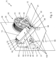
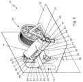
- Figures 5 and 6 show isometric views of the main components of a towline deployment system 10 for one of the towline deployment stations 3.
- the towline deployment system 10 at each of the towline deployment stations 3 works in the same way, the main difference being that the rocket assembly 40 may be oriented at different azimuth angles to the hull. In Figures 5 and 6 this angle is for the sake of simplicity shown as being at 90°, however the deployment angles provided by different line deployment stations will, in general be different.
- the towline deployment system 10 is mounted within the vessel behind a portion of the vessel's hull 25.
- Various components of the towline deployment system are supported on a mounting platform 12, which may be a portion of the ship's internal deck or another platform or deck within the body of the vessel.
- the mounting platform 12 may extend transversely away from an inside surface 26 of the hull 25.
- Other components of the towline deployment system 10 may be mounted to the inside surface 26 of the hull.
- the towline deployment system 10 comprises the main cable reel assembly 50.
- the main cable reel assembly 50 comprises a cable drum or spool 51 supported by a free axle 52 on a cable reel mount or frame 53.
- the gas charging system 20 comprises a source of gas pressure 13, which may be one or more gas cylinder(s), as illustrated.
- the source of pressurised gas need not be provided adjacent to the rocket assembly 40, as illustrated, and may instead be provided at some distance. However, it is preferable that the source of pressurised gas is proximate the rocket assembly to minimise, as far as possible, the length and volume of any interconnecting pipes therefore reducing the time taken to convey pressure from the gas pressure source to the rocket assembly 40 in order to build up the gas pressure necessary to propel the rocket main body 41.
- the gas charging system 20 also comprises a pressure vessel 14 connected to the source of gas pressure 13 by a gas conduit, such as a connecting pipe 15, through which gas flows into an inlet 17 of the pressure vessel 14.
- a gas flow control valve which in this example is a solenoid valve 16, which in this example is mounted on the gas cylinder 13.
- Pressure within the pressure vessel can be monitored using a pressure transducer 18, and over-pressure can be avoided using a pressure safety valve 19.
- the pressure transducer 18 and pressure safety valve 19 are mounted directly to the pressure vessel 14 adjacent to the inlet.
- the control system isolates the gas flow solenoid valve 16 and the towline deployment station 3 changes its status to CHARGED indicating to the operator that the rocket main body 41 is ready to launch.
- the gas charging system 20 further comprises a gas outlet 21 from the pressure vessel 14, leading to a gas release valve 22 that controls the release of pressurised gas into a gas conduit, which in this example is a gas discharge transfer pipe 23.
- the gas transfer pipe then passes into an interior of a rocket launch housing 60.
- the rocket launch housing 60 is elongate and extends within the vessel transversely away from the hull 25 at a downwards angle.
- the angle may be between 0° and 85° to the horizontal and is most preferably between about 40° and 50° to the horizontal.
- a mounting plate 61 is provided and joined to the housing 60 by a weld along a seam 63 between the housing 60 and the mounting plate 61.
- the hull mounting plate 22 is affixed by welding or other suitable means to the hull inside surface 26, providing a method of locating and securing mounting plate 61 in position.
- the mounting plate 61 may be secured to the hull mounting plate 22 by studs or bolts or other suitable means allowing the rocket launch housing 60 to be removed if required for routine maintenance or if it becomes necessary to install a new rocket from within the vessel.
- the mounting plate 61 may be permanently affixed to the inside surface of the hull, for example by welding (not shown). In either case, the rocket launch housing 60 is held in a fixed relationship with respect to the hull 25.
- Figure 6 shows a partly cut-away isometric view of the towline deployment system 10, in which one side of the rocket launch housing 60 is cut away to illustrate components within the housing, in particular the rocket main body 41 and the heaving line tail 31'.
- the heaving line tail 31' extends away from a lower end 44 of the rocket main body 41.
- This also shows how the housing mounting plate 61 has an aperture 64 aligned with a matching rocket launch aperture 65 in the hull through which the rocket main body 41 is, in use, launched.
- the heaving line tail 31' extends from the lower end 44 of the rocket main body along the inside of the rocket launch housing 60 and out through the rocket launch aperture 65.
- the housing has an aperture 67 from which extends a drain outlet 68 for discharging any water that may collect inside the rocket launch housing.
- the drain outlet 68 may be connected to any suitable drainage system but may conveniently exit the hull 25 directly through a drainpipe 69 as illustrated.
- any water ingress into the rocket launch housing for example from rain or waves lapping the rocket launch aperture 65 is immediately drained away through the drain outlet 68.
- the heaving line 31 is most preferably integrated within the rocket main body 41.
- the rocket main body 41 is elongate in a forwards launch direction 90 and, in this example, comprises a similarly elongate heaving line housing 42 attached to one side of a substantially cylindrical rocket outer casing 43.
- the heaving line housing 42 holds a sealed heaving line assembly 70, which is replaceable after use or during servicing.
- the heaving line tail 31' is fed from the rocket launch housing 60 in the forwards direction 90 out through the rocket launch aperture 65 in the hull 25 and then across an outer surface of the hull (not shown) and then back into the hull through an aperture 39' in a panama chock 39.
- the heaving line is then connected to the messenger cable 32 of the main cable reel assembly 50.
- the heaving line may optionally be protected where it traversed the exterior of the hull by a channel member 190 as part of a line management system.
- the rocket launch housing 60 provides physical protection to the rocket assembly 40, and also provides a passage for the heaving line tail 31', which extends from the lower end 44 of the rocket main body 41 upwards along a base or floor 45 within the rocket launch housing 60, past an upper end 46 of the rocket main body 41 and out through the rocket launch aperture 65.
- Figure 7 shows a side elevation showing the main, externally visible, components of the pneumatic rocket system 20, 40, apart from the source of pressurised gas 13, the solenoid valve 16 and pipework 15.
- the rocket assembly 40 Prior to launch, the rocket assembly 40 is restrained from movement in the launch direction by a locking mechanism 80 which makes a connection between the gas charging system 20 and the rocket assembly 40.
- the gas charging system 20 and the rocket assembly 40 are initially secured together by the locking mechanism 80 such that the rocket assembly is initially restrained from separating from the gas charging system.
- the locking mechanism 80 is preferably provided proximate the lower end 44 of the rocket main body 41.
- the locking mechanism 80 in this example is a push-pull connector that comprises a clasp mechanism 81, which in this example is a locking ring.
- the clasp mechanism is configured to release automatically the rocket assembly 40 from the gas charging system 20 when a releasing force urging the rocket assembly in the launch direction exceeds a predetermined level.
- the releasing force is provided by a flow 92 of pressurised gas from the fully pressurised pressure vessel 14 through a rocket launch tube 91 and into a rocket pressure tube 47 that extends in the launch direction from the lower end 44 of the rocket main body 41 towards a rocket nose 82 at the upper end 46 of the rocket main body 41.
- the clasp mechanism 81 is configured to release automatically the rocket assembly 40 from the gas charging system 20 immediately prior to launch of the rocket assembly.
- the rocket nose is a strobe light 82 at the upper end 46 of the rocket main body 41.
- high visibility reflective panels or markings 83 may be applied externally on the rocket main body 41 to aid recovery by the rescue vessel 102.
- the strobe sequence can be controlled by a microcontroller to offer a continuous on / off / wait ratio or could flash any sequence message in international Morse code such as "dot dot dot, dash dash dash, dot, dot, dot, indicating SOS.
- FIG 8 shows a partly sectioned side elevation of the pneumatic rocket system showing the internal components of the rocket assembly 40.
- the rocket outer casing 43 is substantially cylindrical and houses coaxially a substantially cylindrical rocket pressure tube 47.
- a rearwards or lower end portion 27 of the rocket pressure tube projects out of an aperture 49 in a rearwards or lower end 48 of the rocket outer casing 43.
- this rearwards or lower end portion 27 of the rocket pressure tube 47 provides a seat 84 that provides part of the locking mechanism 80.
- the seat releasably engaged with the clasp mechanism 81.
- a space between the rocket pressure tube 47 and the rocket outer casing 43 is a substantially annular volume 87', except for a space between a forwards or upper end 29 of the rocket pressure tube where a substantially disc-shaped front wall 85 of the rocket pressure tube is separated from a substantially disc-shaped front wall 86 of the rocket outer casing by a by a substantially cylindrical volume 87".
- These volumes 87', 87" are preferably filled with a low-density material such as polystyrene to provide some mechanical rigidity to the construction and also so that the rocket main body 41 floats when immersed in water.
- the rearwards or lower end portion 27 of the rocket pressure tube 47 terminates in an opening 115 into which is received rocket the launch tube 91, which is static during launch.
- the rocket pressure tube 47 has a radially inwards facing, or inner, cylindrical internal surface 88 that has a close sliding fit over an outer cylindrical surface 89 of the rocket launch tube 91.
- the rocket launch tube is a forwardly directed extension of the gas transfer pipe 23, and therefore is part of the gas charging system 20.
- a forwards end 116 of the rocket launch tube 91 provides an opening 117 which, in use directs pressurised gas against a closed end of the rocket pressure tube 47 provided by the front wall 85.
- both of the opposing surfaces 88, 99 of the rocket pressure tube 47 and rocket launch tube 91 are cylindrical, sharing a common axis 24, however, these surfaces may be non-circular in section so that the orientation between the rocket pressure tube and the rocket launch tube is rotationally fixed.
- the gas pressure against the front wall 85 of the rocket pressure tube 47 creates a force urging the rocket pressure tube, and hence the rest of the rocket assembly 40, in the forwards launch direction 90.
- this force is resisted by the clasp mechanism 81, which bears on the rearwards or lower end portion 27 of the rocket pressure tube 47. Details regarding the clasp mechanism 81 will be described in more detail below, and are illustrated in Figures 11, 12A, 12B and 12C .
- the heaving line housing 42 contains a cylindrical receptacle 72 that defines an axis 99 which preferably extends parallel with the launch direction 90.
- the receptacle 72 has an aperture or opening 73 that faces towards the lower end 44 of the rocket main body 41.
- the heaving line cartridge 71 is inserted into the cartridge receptacle through the aperture or opening 73 towards a disc-shaped end wall 74 of the receptacle and is then engaged within the cartridge receptacle 72 by matching cartridge engagement features 77, 78 between the cartridge receptacle and the heaving line cartridge 71, to be described in more detail below.
- the engagement features help to ensure that the heaving line cartridge 71 does not fall out of the receptacle 72 when the rocket assembly 40 is launched.
- the heaving line cartridge 71 is further secured in the receptacle 72 by a retention ring 95 which is inserted into the opening 73 once the heaving line cartridge is engaged within the receptacle.
- the retention ring makes a close sliding fit with the cylindrical receptacle and is secured in place in by bolts 96 that pass through the tubular outer wall 75 of the heaving line housing into the retention ring.
- the retention ring 95 presents an aperture 97 for a watertight plug 58 which seals the heaving line cartridge 71 within the cartridge receptacle 72.
- the watertight plug is substantially disc shaped.
- the engagement between the plug and opening 73 in the receptacle 72 may be a friction fit, or may be, as illustrated be provided by one or more O-rings, in this example a forwards O-ring 93 and a rearwards O-ring 93', which are compressed to provide a seal between the retention ring aperture 97 and the plug 58.
- the retention ring 95 is recessed within the receptacle opening 73 and the plug 58 preferably has an annular flange 94 that extends radially outwards to cover the retention ring 95.
- This flange 94 prevents the plug being pushed in past its operation position where the inner O-ring 93 would disengage with the inner bore of the retention ring 95. If this were to happen, the inner O-ring could fully expand which might prevent the watertight plug 58 from ejecting during launch.
- the flange 94 ensures the correct positioning of the plug 58 with respect to the retention ring 95 which helps to ensure a good seal around the retention ring and over the receptacle opening 73.
- the heaving line cartridge 71 has a tubular outer wall 75 with substantially cylindrical inner and outer surfaces that are concentric with the receptacle axis 99 when the cartridge is loaded into the receptacle 72.
- the tubular outer wall 75 is substantially closed by an end wall or cap 76.
- the heaving line cartridge 71 is preferably provided with an axially threaded portion 78 which engages with a matching threaded feature 77 within the cartridge receptacle72.
- the axially threaded portion is a threaded bore 78 in the end wall or cap 76 of the heaving line cartridge
- the matching threaded feature is a threaded end 77 of a connection tube 28 that provides a gas inlet and which protrudes axially into the receptacle through the end wall 74 of the receptacle.
- the end wall 74 of the receptacle 72 is provided with a threaded bore 79 through which the threaded end 77 of the gas inlet tube 28 is engaged such that this protrudes into the receptacle 72 along the receptacle axis 99.
- the heaving line cartridge is rotated about its axis 99 to screw the threaded end 77 of the gas inlet tube into the threaded bore 78 in the end wall or cap 76.
- the threaded end 77 of the gas inlet tube 28 and threaded bore 78 of the end wall or cap 76 of the cartridge therefore provide matching cartridge engagement features 77, 78 between the cartridge receptacle 72 and the heaving line cartridge 71.
- the heaving line cartridge is removeably engaged within the receptacle and can be replaced either after use of the towline deployment system 10 or after inspection of the coiled heaving line 31.
- matching cartridge engagement features may, alternatively, be used, for example a bayonet fitting within the receptacle or a latch with a release mechanism accessible on the heaving line housing, such as a manually operable button.
- gas inlet tube threaded end 77 is screwed into the threaded bore 79 in the end wall 74 of the receptacle
- other forms of construction may alternatively be used, such as a welded or glued seam around a plain aperture in the end wall 74 (not illustrated).
- the watertight plug 58 is automatically released during launch.
- the heaving line 31 is hollow wound within the receptacle and centrally drawn which results in minimal friction in deployment. As the rocket assembly 40 travels through the air, the heaving line 31 unwinds and plays out until the rocket assembly comes to rest, in most cases by splashing down into the water. If the heaving line becomes fully unwound, an end of the heaving line is retained within the cartridge at an anchor point 59.
- heaving line cartridge 71 is sealed from environmental conditions, for example, salt water or ultraviolet rays, which could degrade its mechanical properties.
- a space 87 between the end wall 74 of the receptacle 72 and the heaving line housing 42 through which the gas inlet tube 28 passes is preferably filled with a low-density material such as polystyrene to provide some mechanical rigidity to the construction and also to increase buoyancy in water of the rocket main body 41.
- FIGs 10A and 10B shows part of a second embodiment of a towline deployment system 10', particularly those which differ from those of the first embodiment 10.
- the second embodiment has a pneumatic rocket system in which the same features as described above are indicated using the same reference numerals.
- the second embodiment 10' has a pneumatic rocket system that comprises a rocket assembly 40' that is rotatable between a stowed position, as shown in Figure 10A , and an active position, as shown in Figure 10B .
- the rotation is provided by a joint in a rotatable coupling 98 between the gas transfer pipe 23' and a locking mechanism 80' which again is a push-pull connector comprising a clasp mechanism, preferably a locking ring 81 that is the same as that described above.
- the rotatable coupling 98 extends around the gas conduit that conveys pressurised gas to the rocket assembly 40'.
- FIGS 10A and 10B only part of the gas charging system 20' is shown, including the pressure vessel 14' and downstream connections and pipework 21', 22, 23'.
- the upstream components gas supply components are preferably the same as illustrated and described above.
- the gas transfer pipe extends vertically upwards through a mounting platform 12', which is an exposed section of the outer deck.
- the rotatable coupling 98 provided rotation in a plane inclined to the horizontal so that the in one rotational orientation of the rotational coupling 98, the axis 24' of the rocket pressure tube and rocket launch tube is at a maximum angle to the horizontal.
- the rotational plane of the coupling may be set to be the desired launching angle to the horizontal, as shown in Figure 10B .
- the rotational coupling is rotated through 90° until the axis 24" of the rocket pressure tube and rocket launch tube is horizontal, as shown in Figure 10A .
- this axis 24" may, for the sake of convenience, be parallel to the side of the vessel, to reduce the required storage space.
- the rotational coupling 98 may be driven by a pneumatic actuator, a hydraulic piston and cylinder, an electric actuator or a motor having a pneumatic, hydraulic or electrical source of power, and may be controlled either locally or remotely by the remote control system 5, 5'.
- the coupling could provide more than one axis of rotation, including elevation or azimuth rotation between the stowed and active orientations.
- Figures10A and 10 B show a movement of 90° of rotation in azimuth and 45o of rotation in elevation, but different types of rotation coupling can provide rotation from 0° to ⁇ 180° in all axes.
- the rocket assembly 40' could move in the vertical axis prior, during or after any angular rotation.
- the rocket assembly 40' may be may be protected by an outer covering having an aperture through which the rocket is to be launched, and this aperture could open or be protected by a waterproof hatch depending on the application.
- Figure 11 shows an isometric schematic view of the locking mechanism 80 and the locking ring 81 for securing and then releasing the rocket assembly 40
- the locking ring is the same in both the first and second embodiments of the invention.
- the locking mechanism 80' of the second embodiment differs from that 80 of the first embodiment only in the details of the ways these are mounted to the respective gas transfer pipes 23, 23'.
- Figures 12A, 12B and 12C show sectioned views of the locking ring 81 in which the rocket pressure tube 47 is axially positioned over the rocket launch tube 91, and retained in position by the locking ring 81.
- the locking mechanism 80 comprises a mounting portion 101 that supports the locking ring 81 and which therefore secures the positioning of the locking mechanism 80 and therefore also the positioning of the rocket assembly 40 when this is engaged with the connector.
- the locking ring 81 is also supported by the mounting portion 101.
- the locking ring comprises a collar 118 that extends from the mounting portion towards the lower end 44 of the rocket main body 41.
- the collar 118 holds at least one ball catch 120, and in this example, there are eight ball catches 120 equally spaced apart around the circumference of the collar 118.
- Each ball catch 120 comprises a spring-loaded ball 121 or other similar member having a rounded tip held within a bore 108.
- the mounting portion 101 is preferably a sleeve, which may conveniently be mounted around the rocket launch tube 91 The collar 118 may then extend in the launch direction forwards from the mounting portion.
- the ball catches 120 are spaced apart from one another in a band that extends circumferentially around the collar 118.
- the interior surfaces of the collar 118 and of the sleeve are coaxial and are radially stepped at an annular ledge 119, with a first cylindrical inner surface 103 within the collar extending from the ledge towards a forwards end 104 of the connector 80 and a second cylindrical inner surface 105 towards extending from the ledge 119 towards a rearwards end 106 of the connector.
- the second cylindrical surface 105 is securely connected to the outer surface 89 of the rocket launch tube 91.
- the mounting portion 101 and the collar 118 share a common outer surface 109, which is preferably cylindrical, but which could have a different form, for example being hexagonal in section if the connector 80 was joined to the rocket launch tube 91 by matching threads.
- This connection may be made in many ways, for example by an interference fit between the rocket launch tube 91 and the connector 80.
- the connector 80 and/or the rocket launch tube 91 are joined to the gas transfer pipe 23. This may be done in many ways and is shown schematically in Figs. 12A-C to illustrate how the flow of compressed gas 92 is conveyed into the rocket launch tube 91.
- the first cylindrical inner surface 103 is stepped radially outwards relative to the second cylindrical inner surface 105, so that the collar 118 and rocket launch tube 91 together present a substantially annular forwards facing socket or receptacle 107 that is configured to receive and releasably hold the rearwards or lower end portion 27 of the rocket pressure tube 47.
- Each ball 121 is seated in one of the bores 108, which extend radially between the first inner cylindrical surface 103 of the sleeve and the outer surface 109 of the connector 80.
- Each ball 121 is spring-biased radially inwards within the bore 108. This may be accomplished by different types of spring-biasing means, for example, a leaf spring, an expanding clip or a coil spring that is radially outwards of each ball and that is constrained by a plug in the bore to act radially inwards on the ball.
- the spring biasing is provided by an elastomeric ring, for example an O-ring 110 that is seated in a groove 111 that extends circumferentially around the outer surface 109 of the collar 118 and centered on the band of radially extending cylindrical bores 108.
- the arrangement is such that tension in the elastomeric ring 110 urges each one of the balls 121 to bear on the seat 84 on the rocket pressure tube 47.
- the seat therefore functions as a cylindrical latch plate 84.
- the locking ring 81 is provided by one or more ball clasps 120 each of which has a corresponding ball 121 or similar member with a rounded tip that is spring-biased inwards and slidable within the radially extending bore 108 through the collar 118.
- the connector 80 is provided by the locking ring 81 and its arrangement with respect to the collar 118, and also the configuration of the collar 118, the mounting portion 101 and the rocket launch tube 91 which provide therebetween the socket 107 inside of which the locking ring 81 engages with and disengages with the rocket pressure tube 47.
- the latch plate function of the seat 84 is provided by a plurality of radially outwardly facing pockets or recesses 112, corresponding in number to the number of radially inwardly biased balls 121.
- the recesses 112 are spaced apart circumferentially around an outer cylindrical surface 113 of the end portion 27 of the rocket pressure tube 47.
- the recesses 112 are preferably part-spherical, to match the projecting shape of the balls 121 which reduces dynamic friction with the balls when the end portion 27 of the rocket pressure tube 47 is pressed in the socket 107 during assembly or pulled out of the socket during servicing or during launch of the rocket assembly 40.
- the bias of the O-ring 110 transmitted on the array of balls 121 pressed into the recesses 112 is sufficient to hold the rocket pressure tube 47, and hence to rest of rocket assembly 40, securely to the locking ring 81.
- the rocket launch tube 47 then free to be propelled in the launch direction 90 as the pressured gas expands within the lengthening combined volumes of the rocket pressure tube 47 and launch tube 91, as shown in Figure 12C .
- compressed gas should still be flowing 92 after the locking ring 81 disengages, so that that the force on the rocket launch tube 47 may still be increasing, as indicated in Fig. 12C by an arrow 130".
- the locking ring 81 and the seat 84 are designed to disengage when the pressure of the delivered compressed gas reaches a predetermined pressure. Therefore, to ensure reliable functioning, the gas flow 92 should be sufficient to exceed the expected gas pressure to ensure that the predetermined pressure is reached.
- the release of the end portion 27 of the rocket pressure tube 47 from the locking ring 81 allows the bias of the O ring 110 to move the balls 121 inwards onto the rocket launch tube 91.
- the arrangement is such during refurbishment or servicing of the rocket assembly 40, an end 114 of the same or another rocket pressure tube 47 may be pressed axially into the socket or receptacle 107 to engage with the locking ring 81.
- the rearwards end 114 of the rocket pressure tube may there be chamfered to ease each of the spring-biased balls onto the end of the outer cylindrical surface 113 of the rocket pressure tube during this process.
- restraining catch mechanism including a collar clasp with a circumferential arrangement of castellations and matching radial grooves in order to hold rocket assembly in place during storage and provide sufficient retention during the period in which gas pressure is built up within the rocket launch tube 91 prior to launch.
- the locking ring 81 resists the growing forwards force 130' imparted to the rocket pressure tube 47 by the increasing gas pressure during the initial pressurisation thereby preventing the rocket assembly 40 from separating from the locking mechanism 80, 80'. This helps to increase the energy transfer from compressed gas to kinetic energy during the launch process and therefore improves the overall efficiency in the launching of the rocket assembly 40.
- the outer surface 89 of the rocket launch tube 91 and the inner surface 88 of the rocket pressure tube make a close sliding fit 47 which helps to prevent pressurised gas from escaping between these components during the launch process.
- clearances between surfaces may be such that during launch compressed gas is distributed between the outer surface 89 of the rocket launch tube 91 and the inner surface 88 of the rocket pressure tube providing a gas bearing reducing the friction during launch.
- the rocket launch tube may optionally be provided with a plurality of perforations in to increase the effect of this gas bearing.
- the surface area of the perforations is sufficiently small, for example 10% of the area of the opening 117 at the forwards end 116 of the rocket launch tube 91, so that these perforations do not cause a significant loss in pressure as the rocket launch tube becomes exposed as the rocket assembly accelerates in the launch direction.
- the rocket launch process is as follows. A signal is sent to the solenoid valve 16 which opens, allowing high pressure gas to transfer into pressure vessel 14 through the connecting pipe 15.
- the initial pressure of the gas cylinder 13 is preferably around 20000 kPa (3000 PSI).
- the pressure will drop as gas is transferred to the rocket assembly 40, and this drop will depend on the relative volumes of the pressure vessel 14, connecting pipe 23, and cavities within the rocket assembly 40 that become pressurised during the launch of the rocket main body 41.
- the volume of the pressure vessel 14 is sufficient such that the operating pressure during launch is no less than about 1200 kPa (175 PSI).
- the operating pressure may, however, be between about 10 kPa to about 10000 kPa depending on how far the rocket main body 41 is designed to travel during deployment of the heaving line 31.
- the high-pressure vessel 14 is provided with at least one pressure release safety valve 19.
- inert gases such as argon (Ar), although different gases can be used if required such as nitrogen (N2).
- the system monitors pressure the pressure transducer 18. When the operating pressure is achieved within the pressure vessel 14, the system status changes to SYSTEM CHARGED as shown in Figure 3 . Additionally, the rocket strobe in the rocket nose 82 can be activated via the control system so that the crew on the rescue vessel 102 can see the initial launch position and follow the trajectory path 9' of the rocket main body 41.
- a battery within the rocket strobe can be charged inductively by locating one coil in the rocket main body 41, one in the rocket launch housing 60 or by a breakaway electrical connection which separates during launch.
- a communication system can be provided to enable the strobe or to provide information on the rocket strobe light status, including information regarding the battery voltage.
- Figure 9 shows a partly sectioned side elevation of the pneumatic rocket system 20, 40 during launch.
- the gas release valve 22 opens, allowing pressurised gas to flow from the high-pressure cylinder 14, into the rocket launch tube 91 via the gas transfer pipe 23.
- the gas pressure inside the rocket launch tube 91 acts upon the closed end 85 of the rocket pressure tube 47, causing the locking ring 81 to release the rocket assembly 40 which then accelerates axially along the rocket launch tube 91.
- the launch velocity may be of the order of 45m/s. If the launch tube is about 2m long, the required launch acceleration would therefore be about 500 m/s2, or about 50g.
- the gas inlet tube 28 extends between the rocket pressure tube 47 and cylindrical receptacle 72 for the heaving line cartridge 71.
- high pressure gas is transferred from the rocket pressure tube through the gas inlet tube 28 and into the heaving line cartridge 71. This causes gas pressure inside the receptacle to build up.
- the receptacle 72 is sealed against ingress of water by the watertight plug 58, which is initially held in place by static friction between the plug and the retention ring 95.
- the watertight plug 58 When the gas pressure bearing on the watertight plug 58 exceeds the maximum static friction retaining force, the watertight plug 58 is ejected, thereby opening the aperture 97 for the heaving line 31.
- the aperture 97 is large enough such that the heaving line 31 can play out without significantly affecting the trajectory and distance travelled by the main rocket assembly 40.
- FIGS 17A and 17B An example using break away panels is illustrated in Figures 17A and 17B .
- the plug is divided circumferentially into three equal segments 58A, 58B, 58C which when assembled extend around the circumference of the heaving line 31. The segments fall away from the heaving line as soon as the plug 58A, 58B, 58C is pulled out of the receptacle aperture.
- the ratio between the cross-sections of the rocket pressure tube 47 and the gas inlet tube 28 is, in this example, around 100:1, therefore offering a low overall performance loss to the main rocket assembly once the sealed heaving line assembly 70 operates and vents to atmosphere.
- the rocket main body 41 and the attached heaving line 31 both hit the sea and float at a safe distance from the rescue vessel 102, for example 50 m to 200 m from the stricken vessel 2, allowing the rocket strobe light in the rocket nose 82 and reflective markings 83 to guide the crew of the rescue vessel to the rocket main body 41 and heaving line 31 and thereby facilitate easy and safe recovery.
- Other systems of identification and location can be utilised including dye systems or radio beacon technology.
- the rocket strobe light in the rocket nose 82 may optionally flash a single colour such as red, meaning port, or green, meaning starboard, or may utilise other colours or colour sequence patterns or flash patterns to make the strobe more conspicuous over a range of different ambient lighting conditions, atmospheric conditions or sea conditions.
- the heaving line 31, then the messenger line 32 and finally the tow cable 33 of the towline can be pulled onto the rescue vessel.
- the main towline 33 can then be secured to the rescue vessel's towline and the rescue vessel's towline then payed out up to 500 m providing a safe distance between the stricken vessel 2 and the rescue vessel, following which the stricken vessel can be towed to safety.
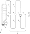
- Figure 13 shows how the towline assembly 30 comprises a first connection 35 between the heaving line 31 and the messenger cable 32, a second connection 36 between the messenger cable 32 and the tow cable 33, and a towline stop 37 (also called a cable stop or a stop end) at the end of the tow cable.
- the towline stop 37 is configured to engage with an aperture in a structural anchorage point, for example the aperture 39' in the panama chock 39 in the hull 25.
- a panama chock is not the only type of structural anchorage point which may be employed. Instead of the panama chock 39, other types of known dedicated stop points for a cable stop end may, alternatively, be used.
- FIG 14 shows a second type of structural anchorage point, referred to herein as a towing cable stop 139.
- the towing cable stop has an aperture 139' through which the towing cable passes and with which the towline stop 37 is engaged.
- the tow cable 33 has been completely unwound from the drum and the final towline stop 37 locates in the aperture 139' of the towing cable stop 139 which is designed and engineered to take the high load forces under towing conditions.
- a control cable 34 is, optionally, connected to the towline stop 37 and is itself terminated by a termination connection 38.
- the cable and reel layouts shown in the drawings are for illustration purposes only and the position of the main cable reel assembly 50 and the panama chock 39 or towing cable stop 139, can be changed to suit various installations on different types of vessel.
- the control line or cable 34 prevents the tow cable 33 and the towline stop 37 from releasing from the cable spool 51. This provides a controlled deployment until the towline stop 37 locates within the panama chock 39 or other towing cable stop 139.
- the control cable 34 is longer than the distance between the cable spool 51 and the structural anchorage point 39, 139 and is fixed to the cable spool at the termination connection 38 at the end of the control cable 34.
- the length of the integrated heaving line 31, messenger line 32, tow cable 33 and control line 34 can be optimised for the size and displacement of each vessel fitted with the range from 50 to 1000 metres.
- the length of each line or cable can be adjusted to suit the size of the vessel and other circumstances.
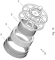
- Figure 15 shows an exploded isometric view of the main cable reel assembly 50, in which the cable spool 51 is first wound with the control line 34, followed by the tow cable 33, and followed by the messenger line 32.
- a disposable interleave can be used between each layer, if required.
- the interleave may be at least one plastic sheet that is wrapped around the outermost layer of the tow cable, and/or around the outermost layer of the control cable and/or the control line 34, in order to provide a smooth base for regularly spaced coils to form as each cable or line is wound. This is useful when the lines to be wound each have different outer diameters, which will generally be the case.
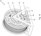
- Figure 16 shows an isometric view of the main cable reel assembly 50 loaded with the control line or cable 34, the tow cable 33 and the messenger line 32.
- the main cable reel assembly 50 is provided with a rotation control system to provide controlled rotational speed over the expected load conditions. This is to prevent the weight of the lines and towing cable exiting the vessel from causing the cable spool 51 to over-speed, which would cause a dangerous situation in operation.
- the rotation control system comprises a reel drive motor 57, which is preferably fixed to the main cable reel mount or frame 53.
- the reel drive motor may be a motor that is powered either to drive or restrain rotation of the reel by any suitable means.
- main cable reel assembly is driven by a belt drive arrangement in which the motor directly turns a drive pulley 54 linked to a reel pulley 55 by a coupling component 56.
- the coupling component 56 between the reel pulley 55 and the reel drive motor 57 can be one or more chain systems, synchro belts or V-belts.
- the reel pulley 55 can be directly coupled to the reel drive motor 57 via a gear arrangement (not shown).
- the coupling component is a belt or a chain 56.
- each pulley 54, 55 has teeth (not shown) which engage with matching features (not shown) of the belt or chain 56 to avoid slippage between the motor and reel.
- the gearing ratio between the motor and reels will depend on the power of the motor and weight of the reel assembly, but may, for example, be between 10:1 and 100:1 in order to increase the torque applied to the reel assembly.
- the reel drive motor 57 may be an electric motor or alternatively may be a hydraulic motor using hydraulic fluid flow control. As an alternative to the motor 57, the reel drive speed may be controlled by a passive device, using a centrifugally driven clutch that engages a brake or may include electrical monitoring to control an electrically driven clutch braking.
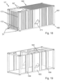
- Figures 18 to 23 shows a third embodiment of a towline deployment system 10".
- the main components are housed within an outer housing which is in the shape of a container 161, thereby providing a container module 160, from which extends at least one heaving line tail 31'.
- the container housing 161 can be manufactured to standard ISO container specifications, and has eight corners 162 with standardised contained lock points, enabling securing, lifting and transporting utilising existing container infrastructure.
- the container module 160 is shown based on a 20 foot (6.6 m) standard container shape, however, other container formats can be utilised with any convenient number mounted on a vessel.
- Figure 19 shows a view of additional internal reinforcement included in the container 161, to provide additional structural integrity against weather conditions experienced by vessels at sea.
- Additional components shown consist of side plate reinforcement panels 163, vertical bar reinforcement panels 164 and axial and cross axial roof reinforcement sections 165.
- the roof reinforcement sections 165 in this example engage with apertures in the side plate reinforcement panels 163 and the vertical reinforcement panels 164 to provide additional structural integrity once welded together.
- the design shown is just an example of how a standard shape container can be reinforced.
- the towline deployment system is a dual system capable of deploying, in dependent from one another, two towlines.
- all the mechanical components are dualled in a side-by-side arrangement.
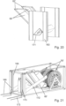
- Figures 18 , 20 and 21 show how a pair of rocket launch housings 60' have an upper end 62' that form openings in a top surface of the container.
- the lower ends 66' of the rocket launch housings 60' connect with a transversely extending drain manifold 171.
- the drain manifold 171 extends though the opposite side plate reinforcement panels 163 on both sides of the container. Any water entering the upper end 62' of the launch housings 60', flows into the drain manifold 171 and exits through one or both sides of the container. Water striking the sides of the container module travels through the drain manifold 171, exiting at the other side.
- Figure 21 shows a view of the container module 160 with side panels, roof panels, and additional reinforcing components removed.
- a pair of cable tubes 172 extend from a pair of tube reinforcement panels 166 to facilitate transmission of lines that play out from a pair of main cable reel assemblies 50', for example, heaving line tails 31', messenger lines 32, tow cables 33 and control lines 34. These lines are wound on dual cable reel assemblies 50' in the same manner as described above.
- the cable tubes 172 are angled downwards from the reel assemblies 50' to help prevent ingress of water under normal conditions.
- the reels 50' operate independently and are provided with a system for controlling rotational speed over the expected load conditions, as described above. This prevents the weight of the lines exiting the vessel to cause the reels to over-speed, which would create a dangerous situation in operation.
- sealing plugs can be incorporated. These can be released automatically by the control system or manually released or detached during playing out of lines and therefore do not hinder the operation of the system.
- the rocket launch housings 60' are shown angled in the azimuth ⁇ 10o from the centreline of the vessel 2, thus generating a distance between port and starboard rocket main bodies 41 when these hit the sea.
- the layout shown has both rockets exiting one end of the container 161 but systems can be designed offering various exiting options, for example opposite ends or opposite sides, and the pneumatic rockets can be installed at any angle to obtain the required exiting trajectory.
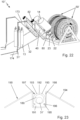
- Figure 22 shows the main components of the container module 160. These are essentially the same as in the first embodiment 10, but doubled up.
- the rocket assemblies 40 are connected to pressure vessels 14 that are pressurised by gas cylinders 13 and which release pressurised gas through release valves 22, transfer pipes 23.
- Locking mechanisms 80 releasably hold down the rocket assemblies 40 until launch.
- Strobes 82 are provided to assist recovery of the rocket assemblies 40.
- Heaving line tails 31' pass along the inside of the rocket housings 60'. Where the heaving line tails exit the upper end 62' of the rocket housings, these each enter a heaving line management system 173 that is located in dedicated recesses in the roof and end panels of the container 161. The heaving line tails 31' exit the heaving line management system 173 and combine with the messenger lines 32 where these both pass through a main line management system 174, also located in a dedicated recess.
- the pair of main line management systems 174 may have sloped external sides 194 to prevent a trip hazard when affixed to the vessel deck 12.
- the heaving line management system 173 and the main line management system 174 provide a line management system 170 for releasably retaining lines extending from the container module 160.
- Figure 23 shows a sectional view through the heaving line management system 176.
- the heaving line tail 31' is protectively held within a channel 180.
- the main line management system 174 has a larger conduit which initially holds the heaving line tail 31', and beneath this the messenger line 32, and so have a larger inner diameter. Apart from this, the main line management system 174 works in the same way as the heaving line management system 173, and so will not be illustrated or described separately.
- the heaving line management system 176 has a channel member 190 that is fixed or adhered to the side of the container 161.
- the channel member has an elongate channel 197 with an internal profile 198 that holds a flexible insert 191.
- the insert has a recess 195 into which is engaged a location feature 196 of the internal profile 198.
- the heaving line tails 31' can be seen retained within the flexible insert 191.
- Other methods of retaining the flexible insert 191 within the channel 197 can be used, including profiles with sections that contract on insertion and expand when an opposing force is applied.
- the insert 191 has a conduit 180 that retains the heaving line under normal conditions but has a slit 192 that allows the heaving line to escape from the conduit 180 when pulled out of the conduit from one end of the slit 192 with a sufficient force, such as may be applied when the heaving line is drawn in manually or by machinery such as a winch on the rescue vessel 102.
- the sides 194 of the channel member 190 extend above the flexible insert 191 to provide protection against knocks or should the channel member be walked over or if items are dragged over the channel member during vessel operation.
- An elongate aperture or slit 192 is aligned centrally within the flexible insert 191 providing two symmetrical deformable sections 193 of the insert either side of the aperture or slit.
- the components of the line management system 173, 174 can be manufactured with a size to suit the particular form of the container 161 or the location on deck 12, and the diameters of the protected portions of the lines.
- the flexible insert 191 could be manufactured in a range of materials including silicon or rubber, and may be produced using extrusion or moulding techniques and provided in bespoke safety colours enabling easy identification.
- the flexible insert 191 could be designed with one compartment as shown or multiple compartments allowing different lines to be stored in different compartments.
- the channel member 190 could be manufactured in different designs and manufactured using extrusion or fabrication techniques.
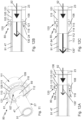
- Figure 24 shows three different time sequential views of the channel member 190 during storage and deployment conditions.
- the uppermost view shows the heaving line tail 31' under storage conditions located within the flexible insert 191.
- the middle view shows the messenger line 32 pulled through the flexible insert 191 resulting in a portion of deformable sections 193 opening to allow the heaving line tail 31' to pass through the flexible insert 191 at a moving opening 199 which recloses after the exiting heaving line tail 31' has passed.
- the lower view shows the heaving line tail 31' after this has travelled through the flexible insert 191 from which it can be seen that deformable sections have returned to their initial status.
- the main line management system 174 works in the same way, initially releasing the heaving line tail 31' and then the messenger line 32 once this becomes taut.
- Figure 25 shows a view of the container module 160 located on vessel deck 12 showing the operational layout.
- the heaving line tails 31' exit the rocket launch housing 60', travel through the heaving line management systems 173 and the main line management systems 174, and exit and join the messenger lines 32 at the connection points 35.
- the messenger lines 32 each travel over the structural anchorage point 139 and the hull 25', which in this example is the bow of the vessel, and then return through the panama chock 39, through the aperture 139' in the anchorage point 139 and into the main line management system 174.
- the lines then each enter the respective cable tube 172 and are wound on the respective main reel assembly.
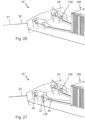
- Figure 26 shows the configuration of the towline deployment system 10" after deployment of the port rocket assembly 40, when the rocket assembly and the heaving line 31 have been recovered from the water and pulled out.
- the rescue vessel 102 initiates withdrawal of the heaving line tail 31', which releases in a controlled sequence from the containerised line management system, until heaving line 31 and messenger line 32 are drawn out towards the rescue vessel.
- Figure 27 shows a view of the system after the rescue vessel 102 has withdrawn the messenger line 32 and pulled it taut until the tow cable 33 is pulled out through the panama chock 25.
- the tow cable 33 is fitted with the towline stop 37 which locates into the aperture 139' in the structural anchorage point 139.
- the control cable 34 prevents the towline 32, 33 and towline stop 37 from releasing from the reel uncontrollably at high speed, which provides safe deployment of the towline 32, 33 until the towline stop 37 locates with the anchorage point.
- the control cable 34 is therefore longer than the distance between the reel and the anchorage point and remains secured to the reel.
- the invention and in particular its various preferred embodiments described above, therefore provide a convenient and effective system for bringing a stricken vessel under tow.
- the rocket assembly is launched without the need for any person to be in proximity, which improves personal safety.
- There system may be operated without the need for any on-board power, particularly when the cable reel assembly maximum speed is passively controlled by a rotation speed control unit, and may also be operated by the rescue vessel. This is particularly useful when all vessel power is lost.
- the tow cable can also be selected to be suitable for vessel, as it is pre-installed aboard the vessel. Multiple towlines can also be independently and remotely established along different directions to more than one rescue vessel.
- the containerised variant of the invention can also make it easier to retrofit the system to existing vessels.
Landscapes
- Engineering & Computer Science (AREA)
- General Engineering & Computer Science (AREA)
- Chemical & Material Sciences (AREA)
- Combustion & Propulsion (AREA)
- Mechanical Engineering (AREA)
- Ocean & Marine Engineering (AREA)
- Filling Or Discharging Of Gas Storage Vessels (AREA)
Claims (17)
- Système de déploiement d'un câble de remorquage (10, 10', 10") destiné à déployer un câble de remorquage (32, 33) à partir d'un navire marin (2), comprenant :- un système de propulsion de fusée à gaz (100) ;- un ensemble fusée (40, 40') comprenant un corps principal de fusée (41) relié au système de propulsion de fusée à gaz (100) et une cartouche de touline (71) contenant une longueur de touline (31), la cartouche de touline étant maintenue à l'intérieur d'un réceptacle (72) à l'intérieur du corps principal de fusée (41), et le réceptacle présentant une ouverture (73) qui est fermée par un bouchon amovible (58) et à travers laquelle une queue (31') de la touline s'étend à partir du corps principal de fusée et qui une fois retirée libère la touline contenue par la cartouche de touline (71) pour la laisser filer à travers ladite ouverture (73) lorsque le corps principal de fusée (41) est propulsé à partir du navire marin par le système de propulsion de fusée à gaz (100) et ainsi déployer la touline ;- un point d'ancrage structural (39, 139) sur le navire marin, le point d'ancrage structural (39, 139) comprenant une ouverture (39', 139') destinée à venir en prise avec une butée de câble de remorquage (37) ; et- un câble de remorquage (32, 33) d'une certaine longueur, installé dans le navire marin, ladite longueur s'étendant entre des première et seconde extrémités opposées et comprenant au niveau de la seconde extrémité la butée de câble de remorquage (37) destinée à venir en prise avec le point d'ancrage structural (39, 139) et la première extrémité de ladite longueur de câble de remorquage étant reliée à la queue (31') de la touline (31) à travers l'ouverture du point d'ancrage structural moyennant quoi la touline une fois déployée est configurée pour tirer le câble de remorquage (32, 33) à travers l'ouverture (39', 139') dans le point d'ancrage structural (39, 139) jusqu'à ce que la butée de câble de remorquage (37) soit mise en prise avec ladite ouverture.
- Système de déploiement d'un câble de remorquage (10, 10', 10") selon la revendication 1, dans lequel la première extrémité du câble de remorquage (32, 33) est reliée à la queue (31') de la touline (31) par au moins une ligne de transmission (32).
- Système de déploiement d'un câble de remorquage (10, 10', 10") selon la revendication 1 ou la revendication 2, dans lequel le câble de remorquage (32, 33) est enroulé sur un tambour (51).
- Système de déploiement d'un câble de remorquage (10, 10', 10") selon la revendication 3, dans lequel le tambour (51) est logé dans un cadre (53) fixé sur un pont (12) du navire marin (2).
- Système de déploiement d'un câble de remorquage (10, 10', 10") selon l'une quelconque des revendications 1 à 4, l'ensemble fusée (40, 40') comprenant en outre un mécanisme de verrouillage (80, 80') et un tube de pression de fusée (47), dans lequel le système de propulsion de fusée à gaz (100) comprend :- un réservoir sous pression (14) relié à une source de gaz sous pression (13) ;- une soupape de libération (22, 22') destinée à libérer un gaz sous pression du réservoir sous pression ;- un tube de lancement de fusée (91) destiné à lancer l'ensemble fusée (40, 40') et étant configuré pour recevoir un gaz sous pression du réservoir sous pression (14) à travers la soupape de libération (22, 22') ; et- une bague de verrouillage (81) sur le tube de lancement de fusée (91), la bague de verrouillage étant mise en prise avec le mécanisme de verrouillage (80, 80') moyennant quoi le tube de pression de fusée est retenu sur le tube de lancement de fusée avant la mise sous pression du tube de lancement de fusée ; dans lequel- le tube de pression de fusée (47) présente une ouverture dans laquelle le tube de lancement de fusée (91) est reçu de manière coulissante, le tube de lancement de fusée permettant à un gaz sous pression de s'écouler dans le tube de pression de fusée et d'agir sur une extrémité fermée du tube de pression de fusée en poussant ainsi le tube de pression de fusée (47) à coulisser le long du tube de lancement de fusée (91) ; et- le mécanisme de verrouillage est configuré pour être libéré lors de la mise sous pression du tube de pression de fusée (47) libérant ainsi le tube de pression de fusée pour son coulissement le long du tube de lancement de fusée (91) moyennant quoi l'ensemble fusée (40, 40') est, lors de l'utilisation, propulsé dans une trajectoire de lancement.
- Système de déploiement d'un câble de remorquage (10, 10', 10") selon la revendication 5, dans lequel le réceptacle (72) dans le corps principal de fusée (41) est relié au tube de pression de fusée (47) par un tube de liaison (28) qui est configuré pour transporter une pression de gaz entre le tube de pression de fusée et la cartouche de touline (71), moyennant quoi la cartouche de touline est mise sous pression avec un gaz suite à la mise sous pression du tube de pression de fusée (47), ledit gaz mis sous pression à l'intérieur de la cartouche de touline (71) agissant sur une face du bouchon (58) et provoquant, lors de l'utilisation, la libération par le bouchon de la touline (31) à l'intérieur de la cartouche pour son déploiement lorsque le corps principal de fusée (41) est propulsé dans ladite trajectoire de lancement.
- Système de déploiement d'un câble de remorquage (10, 10', 10") selon la revendication 5 ou la revendication 6, dans lequel ladite liaison entre la queue de touline (31') et la première extrémité de ladite longueur de câble de remorquage passe à travers un chaumard de Panama (39) moyennant quoi la touline une fois déployée est configurée pour tirer le câble de remorquage à travers l'ouverture (39', 139') dans le point d'ancrage structural (39, 139) puis à travers le chaumard de Panama jusqu'à ce que la butée de câble de remorquage (37) soit mise en prise avec ladite ouverture.
- Système de déploiement d'un câble de remorquage (10") selon l'une quelconque des revendications 1 à 7, comprenant en outre un logement de contenant, le logement de contenant comprenant le système de propulsion de fusée à gaz (100), l'ensemble fusée (40, 40') et la longueur de câble de remorquage.
- Système de déploiement d'un câble de remorquage (10") destiné à déployer un câble de remorquage (32, 33) à partir d'un navire marin (2), comprenant au moins un module de contenant (160) fixé en externe sur le navire marin, un point d'ancrage structural (39, 139) sur le navire marin, le point d'ancrage structural (39, 139) comprenant une ouverture (39', 139') destinée à se mettre en prise avec une butée de câble de remorquage (37), et le module de contenant (160) comprenant :- un système de propulsion de fusée à gaz (100) ;- un ensemble fusée (40, 40') comprenant un corps principal de fusée (41) relié au système de propulsion de fusée à gaz et contenant une cartouche de touline (71) contenant une longueur de touline (31) qui est configurée pour être laissée filer à partir du corps principal de fusée lorsque l'ensemble fusée est lancé ; et- un câble de remorquage (32, 33) d'une certaine longueur, installé dans le module de contenant (160), ladite longueur s'étendant entre des première et seconde extrémités et comprenant au niveau de la seconde extrémité la butée de câble de remorquage (37) destinée à venir en prise avec le point d'ancrage structural (39, 139) et la première extrémité de la longueur de câble de remorquage étant reliée à une queue (31') de la touline (31) à travers l'ouverture du point d'ancrage structural moyennant quoi la touline une fois déployée est configurée pour tirer le câble de remorquage (32, 33) à travers l'ouverture (39', 139') dans le point d'ancrage structural (39, 139) jusqu'à ce que la butée de câble de remorquage (37) soit mise en prise avec ladite ouverture.
- Système de déploiement d'un câble de remorquage (10") selon la revendication 9, dans lequel le module de contenant comprend un logement externe avec une première ouverture et une seconde ouverture, la première ouverture étant une extrémité supérieure (62') d'un logement de lancement de fusée à travers laquelle, lors de l'utilisation, le corps principal de fusée est lancé, et la seconde ouverture étant une sortie d'un collecteur d'écoulement de contenant (171), la seconde ouverture étant à un niveau inférieur à la première ouverture, moyennant quoi l'entrée d'eau à travers la première ouverture s'écoule à travers la seconde ouverture.
- Système de déploiement d'un câble de remorquage (10, 10', 10") selon l'une quelconque des revendications 1 à 10, comprenant en outre un système de gestion de câble (170), le système de gestion de câble comprenant au moins une conduite allongée (180) configurée pour maintenir en la protégeant la queue de touline (31'), la conduite présentant une ouverture ou fente allongée (192) qui est configurée pour libérer la queue de touline (31') de la conduite, lorsque la touline (31) est tendue et lorsque la touline déployée (31) est tirée dans sa longueur.
- Procédé de déploiement d'un câble de remorquage (32, 33) à partir d'un navire marin (2) vers un navire de sauvetage (102) au moyen d'un système de déploiement d'un câble de remorquage (10, 10', 10"), le système de déploiement d'un câble de remorquage étant selon l'une quelconque des revendications 1 à 11, le procédé comprenant :- l'agencement de la queue (31') de la touline (31) pour son extension à partir du corps principal de fusée ;- la liaison de la première extrémité de ladite longueur de câble de remorquage (32, 33) à la queue (31') de la touline (31) à travers ladite ouverture (39', 139') du point d'ancrage structural (39 ; 139) ;- l'utilisation du système de propulsion de fusée à gaz (100) pour propulser l'ensemble fusée (40, 40') à partir du navire marin et pour libérer la touline (31) pour la laisser filer lorsque le corps principal de fusée (41) suit une trajectoire de lancement ; et- la récupération et la traction vers le navire de sauvetage de la touline libérée (31) afin de tirer le câble de remorquage (32, 33) vers le navire de sauvetage jusqu'à ce que la butée de câble de remorquage (37) soit mise en prise avec l'ouverture (39', 139') dans le point d'ancrage structural (39, 139) permettant ainsi au navire de sauvetage (102) de remorquer le navire marin (2).
- Procédé selon la revendication 12, en dépendance de l'une quelconque des revendications 1 à 8, dans lequel l'action d'agencement de la queue (31') de la touline (31) de sorte qu'elle s'étende à partir du corps principal de fusée comprend le placement de la cartouche de touline (71) dans le réceptacle (72) à l'intérieur du corps principal de fusée (41) et la fermeture de l'ouverture (73) sur le réceptacle avec le bouchon (58) de sorte qu'une queue (31') de la touline (31) s'étende à partir du corps principal de fusée.
- Procédé selon la revendication 13, dans lequel le procédé comprend l'éjection du bouchon (58) dans la libération de la touline (31) moyennant quoi la touline est laissée filer à travers ladite ouverture (73) à partir de la cartouche de touline (71) lorsque le corps principal de fusée (41) suit la trajectoire de lancement.
- Procédé de sauvetage d'un navire marin (2) avec un navire de sauvetage (102), le navire marin comprenant une pluralité de stations de déploiement de câble de remorquage (3), lesdites stations pouvant être actionnées indépendamment les unes des autres, et comprenant chacune un système de communication (5'), un système de propulsion de fusée à gaz (100) et un système de déploiement d'un câble de remorquage (10, 10', 10"), lesdits systèmes de déploiement de câble de remorquage étant au niveau de différents emplacements (3) sur le navire marin (2) et présentant chacun un point d'ancrage structural (39, 139) sur le navire marin (2) et chaque point d'ancrage structural comprenant une ouverture (39', 139') destinée à se mettre en prise avec une butée de câble de remorquage (37), et le système de déploiement d'un câble de remorquage comprenant :- un câble de remorquage (32, 33) d'une certaine longueur, installé dans le navire marin (2), ladite longueur s'étendant entre des première et seconde extrémités opposées et comprenant au niveau de la seconde extrémité une butée de câble de remorquage (37) ; et- un ensemble fusée (40, 40') comprenant un corps principal de fusée (4) relié au système de propulsion de fusée à gaz (100) et un réceptacle (72) maintenant une cartouche de touline (71) qui contient une longueur de touline (31), configurée pour être laissée filer à travers une ouverture de réceptacle (73) à partir de laquelle une queue (31') de la touline s'étend, la première extrémité de la touline (32, 33) étant reliée à la queue (31') de la touline (31) à travers l'ouverture (39', 139') du point d'ancrage structural (39, 139) ;dans lequel le procédé comprend :- l'envoi d'une demande de communication pour des informations à partir du navire de sauvetage (102) au système de communication de chacune desdites stations (3) ;- l'envoi à partir du système de communication de chacune desdites stations (3) d'une réponse au navire de sauvetage (102) avec des informations confirmant l'angle de disposition et de déploiement de chacune desdites stations par rapport au navire marin (2) et l'affichage des informations à destination d'un opérateur sur le navire de sauvetage pour permettre à l'opérateur de sélectionner une desdites stations pour le déploiement ;- l'envoi d'une demande de communication à partir du navire de sauvetage (102) au système de communication de la station sélectionnée pour amener un système de charge de gaz (20) du système de propulsion de fusée (100) à devenir chargé en gaz sous pression ;- l'envoi à partir du système de communication (5') de la station sélectionnée (3) d'une réponse au navire de sauvetage (102) lorsque le système de charge de gaz (20) est chargé avec un gaz sous pression et l'affichage à destination dudit opérateur d'une indication (6) selon laquelle le système de charge de gaz est chargé ;- l'envoi d'une demande de communication à partir du navire de sauvetage (102) au système de communication (5') de la station sélectionnée (3) pour déployer le corps principal de fusée (41) ;- le déploiement du corps principal de fusée (41) au moyen d'une charge de gaz sous pression à partir du système de charge de gaz (20) pour propulser l'ensemble fusée (40, 40') à partir du navire marin (2) ;- la libération à travers l'ouverture de réceptacle (73) d'une longueur de la touline (31) à partir de l'intérieur de la cartouche de touline (71) lorsque le corps principal de fusée (41) se déplace le long d'une trajectoire de lancement (9') ;- la récupération et la traction vers le navire de sauvetage de la touline libérée (31) afin de tirer le câble de remorquage (32, 33) vers le navire de sauvetage jusqu'à ce que la butée de câble de remorquage (37) soit située dans le point d'ancrage structural (39, 139) permettant ainsi au navire de sauvetage (102) de remorquer le navire marin (2).
- Procédé selon la revendication 15, dans lequel un tube de pression de fusée (47) est incorporé à l'intérieur du corps principal de fusée (41), le système de charge de gaz (20) comprend un réservoir sous pression (14) et le système de propulsion de fusée à gaz (100) comprend un tube de lancement de fusée (91) qui est reçu de manière coulissante à l'intérieur d'une ouverture de tube (115) du tube de pression de fusée (47), le procédé comprenant en outre :- le maintien de ladite charge de gaz sous pression dans le réservoir sous pression (14) ;- la libération de ladite charge de gaz sous pression à partir du réservoir sous pression (14) dans le tube de lancement de fusée (91) pour mettre sous pression le tube de pression de fusée (47) avec un gaz comprimé à partir du réservoir sous pression (14) et pour agir sur une extrémité fermée (85) du tube de pression de fusée (47) jusqu'à ce que le tube de pression de fusée se déplace axialement le long du tube de lancement de fusée (91).
- Procédé selon la revendication 16, dans lequel l'ouverture de réceptacle (73) est initialement fermée par un bouchon amovible (58) à travers lequel la queue de touline (31') passe, et le réceptacle (72) dans le corps principal de fusée (41) est relié au tube de pression de fusée (47) par un tube de liaison (28), le procédé comprenant en outre, lorsque le tube de pression de fusée (47) est mis sous pression avec un gaz provenant du réservoir sous pression (14), le transport de gaz à travers le tube de liaison (28) à partir du tube de pression de fusée dans le réceptacle (72) moyennant quoi le réceptacle devient mis sous pression avec un gaz jusqu'à ce qu'une pression de gaz à l'intérieur du réceptacle soit suffisante pour forcer le bouchon (58) à sortir de l'ouverture de réceptacle (73) libérant ainsi la touline (31) à l'intérieur de la cartouche (71) pour son déploiement à travers l'ouverture de réceptacle (73) lorsque le corps principal de fusée (41) suit la trajectoire de lancement (9').
Applications Claiming Priority (5)
| Application Number | Priority Date | Filing Date | Title |
|---|---|---|---|
| GB201913475A GB201913475D0 (en) | 2019-09-18 | 2019-09-18 | Marine towing system |
| GB201915622A GB201915622D0 (en) | 2019-10-28 | 2019-10-28 | Marine towing system |
| GBGB1916400.3A GB201916400D0 (en) | 2019-11-11 | 2019-11-11 | Marine towing system |
| GBGB2010593.8A GB202010593D0 (en) | 2019-09-18 | 2020-07-09 | Marine towing system |
| PCT/IB2020/058730 WO2021053613A1 (fr) | 2019-09-18 | 2020-09-18 | Système de remorquage maritime |
Publications (3)
| Publication Number | Publication Date |
|---|---|
| EP4031444A1 EP4031444A1 (fr) | 2022-07-27 |
| EP4031444B1 true EP4031444B1 (fr) | 2023-11-08 |
| EP4031444C0 EP4031444C0 (fr) | 2023-11-08 |
Family
ID=74883045
Family Applications (1)
| Application Number | Title | Priority Date | Filing Date |
|---|---|---|---|
| EP20781622.4A Active EP4031444B1 (fr) | 2019-09-18 | 2020-09-18 | Système de remorquage maritime |
Country Status (2)
| Country | Link |
|---|---|
| EP (1) | EP4031444B1 (fr) |
| WO (1) | WO2021053613A1 (fr) |
Families Citing this family (3)
| Publication number | Priority date | Publication date | Assignee | Title |
|---|---|---|---|---|
| CN114963861B (zh) * | 2022-05-17 | 2024-01-12 | 上海东湖机械厂 | 一种自动锁定解锁装置 |
| CN118514807B (zh) * | 2024-07-23 | 2024-09-27 | 大连海事大学 | 基于无人船的自主式可升降水下拖曳系统及其工作方法 |
| CN120828927B (zh) * | 2025-09-19 | 2025-11-21 | 中国极地研究中心(中国极地研究所) | 一种便携式气动绳索潜标回收系统及其使用方法 |
Family Cites Families (4)
| Publication number | Priority date | Publication date | Assignee | Title |
|---|---|---|---|---|
| US4784035A (en) * | 1986-11-24 | 1988-11-15 | Fishfader Stanley S | Remotely actuated tow line throwing device |
| NO930775L (no) * | 1993-03-03 | 1994-09-05 | Andersen Stein Petter | Bergingssystem for ubemannede fartöyer |
| NO179826C (no) * | 1993-11-18 | 1996-12-27 | John Arve Berget | Bergingslinesystem for montering på et fartöy |
| KR101674877B1 (ko) * | 2015-07-06 | 2016-11-14 | 한국해양과학기술원 | 결합장치를 구비한 무인선 |
-
2020
- 2020-09-18 EP EP20781622.4A patent/EP4031444B1/fr active Active
- 2020-09-18 WO PCT/IB2020/058730 patent/WO2021053613A1/fr not_active Ceased
Also Published As
| Publication number | Publication date |
|---|---|
| WO2021053613A1 (fr) | 2021-03-25 |
| EP4031444A1 (fr) | 2022-07-27 |
| EP4031444C0 (fr) | 2023-11-08 |
Similar Documents
| Publication | Publication Date | Title |
|---|---|---|
| EP4031444B1 (fr) | Système de remorquage maritime | |
| US8831393B2 (en) | Unmanned underwater vehicle and device for connection of an optical waveguide cable to an unmanned underwater vehicle | |
| US7882775B2 (en) | Non-lethal restraint device with diverse deployability applications | |
| US8245617B2 (en) | Non-lethal restraint device with diverse deployability applications | |
| KR101301614B1 (ko) | 구명환이 탑재된 무선조종 보트 | |
| EP1934088B1 (fr) | Sous-marin, vaisseau et ensemble pour deploiement d'une charge utile a partir d'un sous-marin | |
| US8096257B2 (en) | Emergency encapsulated lift system | |
| EP1089908B1 (fr) | Dispositif embarque de recuperation d'un homme a la mer permettant l'autorecuperation d'une victime consciente | |
| EP3437978B1 (fr) | Procédés et systèmes de transfert de ligne | |
| GB2203709A (en) | Air vehicle retrieval apparatus | |
| US11591050B2 (en) | Sonobuoy deployable resources | |
| EP0691264B1 (fr) | Procédé perfectionné de destruction d'un objet sous-marin, notamment d'une mine immergée | |
| US20110232469A1 (en) | Safety device with cable or rope cutting in an explosive environment | |
| US12263917B2 (en) | Parachute sea anchor | |
| GB2345667A (en) | Method and apparatus for destruction of drifting sea mines | |
| CN103857587B (zh) | 用于载荷的瞬时断连的断连单元 | |
| US4711196A (en) | Marine survival system | |
| JP2002137790A (ja) | 水難者の救助具および救助方法 | |
| WO1995013958A1 (fr) | Systeme de sauvetage destine a etre monte sur un bateau | |
| JPH08509679A (ja) | 航行不能船曳航装置 | |
| US4313381A (en) | Mooring system | |
| RU2817156C1 (ru) | Способ передачи коммуникаций на аварийный плавучий объект при проведении аварийно-спасательных работ в сложных гидрометеорологических условиях | |
| GB2199004A (en) | Marine survival system | |
| Ardito et al. | Cooperative Autonomous Robotic Towing system: Definition of requirements and operating scenarios | |
| KR20150134179A (ko) | 수중 낙하산을 이용한 자유 낙하식 구명정 진수장치 |
Legal Events
| Date | Code | Title | Description |
|---|---|---|---|
| STAA | Information on the status of an ep patent application or granted ep patent |
Free format text: STATUS: UNKNOWN |
|
| STAA | Information on the status of an ep patent application or granted ep patent |
Free format text: STATUS: THE INTERNATIONAL PUBLICATION HAS BEEN MADE |
|
| PUAI | Public reference made under article 153(3) epc to a published international application that has entered the european phase |
Free format text: ORIGINAL CODE: 0009012 |
|
| STAA | Information on the status of an ep patent application or granted ep patent |
Free format text: STATUS: REQUEST FOR EXAMINATION WAS MADE |
|
| 17P | Request for examination filed |
Effective date: 20220330 |
|
| AK | Designated contracting states |
Kind code of ref document: A1 Designated state(s): AL AT BE BG CH CY CZ DE DK EE ES FI FR GB GR HR HU IE IS IT LI LT LU LV MC MK MT NL NO PL PT RO RS SE SI SK SM TR |
|
| DAV | Request for validation of the european patent (deleted) | ||
| DAX | Request for extension of the european patent (deleted) | ||
| GRAP | Despatch of communication of intention to grant a patent |
Free format text: ORIGINAL CODE: EPIDOSNIGR1 |
|
| STAA | Information on the status of an ep patent application or granted ep patent |
Free format text: STATUS: GRANT OF PATENT IS INTENDED |
|
| INTG | Intention to grant announced |
Effective date: 20230428 |
|
| GRAS | Grant fee paid |
Free format text: ORIGINAL CODE: EPIDOSNIGR3 |
|
| GRAA | (expected) grant |
Free format text: ORIGINAL CODE: 0009210 |
|
| STAA | Information on the status of an ep patent application or granted ep patent |
Free format text: STATUS: THE PATENT HAS BEEN GRANTED |
|
| AK | Designated contracting states |
Kind code of ref document: B1 Designated state(s): AL AT BE BG CH CY CZ DE DK EE ES FI FR GB GR HR HU IE IS IT LI LT LU LV MC MK MT NL NO PL PT RO RS SE SI SK SM TR |
|
| REG | Reference to a national code |
Ref country code: GB Ref legal event code: FG4D |
|
| REG | Reference to a national code |
Ref country code: CH Ref legal event code: EP |
|
| REG | Reference to a national code |
Ref country code: DE Ref legal event code: R096 Ref document number: 602020020792 Country of ref document: DE |
|
| REG | Reference to a national code |
Ref country code: IE Ref legal event code: FG4D |
|
| U01 | Request for unitary effect filed |
Effective date: 20231108 |
|
| U07 | Unitary effect registered |
Designated state(s): AT BE BG DE DK EE FI FR IT LT LU LV MT NL PT SE SI Effective date: 20231113 |
|
| PG25 | Lapsed in a contracting state [announced via postgrant information from national office to epo] |
Ref country code: GR Free format text: LAPSE BECAUSE OF FAILURE TO SUBMIT A TRANSLATION OF THE DESCRIPTION OR TO PAY THE FEE WITHIN THE PRESCRIBED TIME-LIMIT Effective date: 20240209 |
|
| PG25 | Lapsed in a contracting state [announced via postgrant information from national office to epo] |
Ref country code: IS Free format text: LAPSE BECAUSE OF FAILURE TO SUBMIT A TRANSLATION OF THE DESCRIPTION OR TO PAY THE FEE WITHIN THE PRESCRIBED TIME-LIMIT Effective date: 20240308 |
|
| PG25 | Lapsed in a contracting state [announced via postgrant information from national office to epo] |
Ref country code: ES Free format text: LAPSE BECAUSE OF FAILURE TO SUBMIT A TRANSLATION OF THE DESCRIPTION OR TO PAY THE FEE WITHIN THE PRESCRIBED TIME-LIMIT Effective date: 20231108 |
|
| PG25 | Lapsed in a contracting state [announced via postgrant information from national office to epo] |
Ref country code: IS Free format text: LAPSE BECAUSE OF FAILURE TO SUBMIT A TRANSLATION OF THE DESCRIPTION OR TO PAY THE FEE WITHIN THE PRESCRIBED TIME-LIMIT Effective date: 20240308 Ref country code: GR Free format text: LAPSE BECAUSE OF FAILURE TO SUBMIT A TRANSLATION OF THE DESCRIPTION OR TO PAY THE FEE WITHIN THE PRESCRIBED TIME-LIMIT Effective date: 20240209 Ref country code: ES Free format text: LAPSE BECAUSE OF FAILURE TO SUBMIT A TRANSLATION OF THE DESCRIPTION OR TO PAY THE FEE WITHIN THE PRESCRIBED TIME-LIMIT Effective date: 20231108 |
|
| PG25 | Lapsed in a contracting state [announced via postgrant information from national office to epo] |
Ref country code: RS Free format text: LAPSE BECAUSE OF FAILURE TO SUBMIT A TRANSLATION OF THE DESCRIPTION OR TO PAY THE FEE WITHIN THE PRESCRIBED TIME-LIMIT Effective date: 20231108 Ref country code: PL Free format text: LAPSE BECAUSE OF FAILURE TO SUBMIT A TRANSLATION OF THE DESCRIPTION OR TO PAY THE FEE WITHIN THE PRESCRIBED TIME-LIMIT Effective date: 20231108 Ref country code: NO Free format text: LAPSE BECAUSE OF FAILURE TO SUBMIT A TRANSLATION OF THE DESCRIPTION OR TO PAY THE FEE WITHIN THE PRESCRIBED TIME-LIMIT Effective date: 20240208 Ref country code: HR Free format text: LAPSE BECAUSE OF FAILURE TO SUBMIT A TRANSLATION OF THE DESCRIPTION OR TO PAY THE FEE WITHIN THE PRESCRIBED TIME-LIMIT Effective date: 20231108 |
|
| PG25 | Lapsed in a contracting state [announced via postgrant information from national office to epo] |
Ref country code: CZ Free format text: LAPSE BECAUSE OF FAILURE TO SUBMIT A TRANSLATION OF THE DESCRIPTION OR TO PAY THE FEE WITHIN THE PRESCRIBED TIME-LIMIT Effective date: 20231108 |
|
| PG25 | Lapsed in a contracting state [announced via postgrant information from national office to epo] |
Ref country code: SK Free format text: LAPSE BECAUSE OF FAILURE TO SUBMIT A TRANSLATION OF THE DESCRIPTION OR TO PAY THE FEE WITHIN THE PRESCRIBED TIME-LIMIT Effective date: 20231108 |
|
| PG25 | Lapsed in a contracting state [announced via postgrant information from national office to epo] |
Ref country code: SM Free format text: LAPSE BECAUSE OF FAILURE TO SUBMIT A TRANSLATION OF THE DESCRIPTION OR TO PAY THE FEE WITHIN THE PRESCRIBED TIME-LIMIT Effective date: 20231108 Ref country code: SK Free format text: LAPSE BECAUSE OF FAILURE TO SUBMIT A TRANSLATION OF THE DESCRIPTION OR TO PAY THE FEE WITHIN THE PRESCRIBED TIME-LIMIT Effective date: 20231108 Ref country code: RO Free format text: LAPSE BECAUSE OF FAILURE TO SUBMIT A TRANSLATION OF THE DESCRIPTION OR TO PAY THE FEE WITHIN THE PRESCRIBED TIME-LIMIT Effective date: 20231108 Ref country code: CZ Free format text: LAPSE BECAUSE OF FAILURE TO SUBMIT A TRANSLATION OF THE DESCRIPTION OR TO PAY THE FEE WITHIN THE PRESCRIBED TIME-LIMIT Effective date: 20231108 |
|
| REG | Reference to a national code |
Ref country code: DE Ref legal event code: R097 Ref document number: 602020020792 Country of ref document: DE |
|
| PLBE | No opposition filed within time limit |
Free format text: ORIGINAL CODE: 0009261 |
|
| STAA | Information on the status of an ep patent application or granted ep patent |
Free format text: STATUS: NO OPPOSITION FILED WITHIN TIME LIMIT |
|
| U20 | Renewal fee for the european patent with unitary effect paid |
Year of fee payment: 5 Effective date: 20240827 |
|
| 26N | No opposition filed |
Effective date: 20240809 |
|
| PG25 | Lapsed in a contracting state [announced via postgrant information from national office to epo] |
Ref country code: MC Free format text: LAPSE BECAUSE OF FAILURE TO SUBMIT A TRANSLATION OF THE DESCRIPTION OR TO PAY THE FEE WITHIN THE PRESCRIBED TIME-LIMIT Effective date: 20231108 |
|
| REG | Reference to a national code |
Ref country code: CH Ref legal event code: PL |
|
| PG25 | Lapsed in a contracting state [announced via postgrant information from national office to epo] |
Ref country code: CH Free format text: LAPSE BECAUSE OF NON-PAYMENT OF DUE FEES Effective date: 20240930 |
|
| U20 | Renewal fee for the european patent with unitary effect paid |
Year of fee payment: 6 Effective date: 20250902 |
|
| PGFP | Annual fee paid to national office [announced via postgrant information from national office to epo] |
Ref country code: GB Payment date: 20250901 Year of fee payment: 6 |
|
| PGFP | Annual fee paid to national office [announced via postgrant information from national office to epo] |
Ref country code: IE Payment date: 20250911 Year of fee payment: 6 |
|
| PG25 | Lapsed in a contracting state [announced via postgrant information from national office to epo] |
Ref country code: CY Free format text: LAPSE BECAUSE OF FAILURE TO SUBMIT A TRANSLATION OF THE DESCRIPTION OR TO PAY THE FEE WITHIN THE PRESCRIBED TIME-LIMIT; INVALID AB INITIO Effective date: 20200918 |
|
| PG25 | Lapsed in a contracting state [announced via postgrant information from national office to epo] |
Ref country code: HU Free format text: LAPSE BECAUSE OF FAILURE TO SUBMIT A TRANSLATION OF THE DESCRIPTION OR TO PAY THE FEE WITHIN THE PRESCRIBED TIME-LIMIT; INVALID AB INITIO Effective date: 20200918 |