EP4031477B1 - Korb-, insbesondere luftkorbhubvorrichtung - Google Patents
Korb-, insbesondere luftkorbhubvorrichtung Download PDFInfo
- Publication number
- EP4031477B1 EP4031477B1 EP20772365.1A EP20772365A EP4031477B1 EP 4031477 B1 EP4031477 B1 EP 4031477B1 EP 20772365 A EP20772365 A EP 20772365A EP 4031477 B1 EP4031477 B1 EP 4031477B1
- Authority
- EP
- European Patent Office
- Prior art keywords
- link
- rotary
- platform
- basket
- deformation
- Prior art date
- Legal status (The legal status is an assumption and is not a legal conclusion. Google has not performed a legal analysis and makes no representation as to the accuracy of the status listed.)
- Active
Links
Images



Classifications
-
- B—PERFORMING OPERATIONS; TRANSPORTING
- B66—HOISTING; LIFTING; HAULING
- B66F—HOISTING, LIFTING, HAULING OR PUSHING, NOT OTHERWISE PROVIDED FOR, e.g. DEVICES WHICH APPLY A LIFTING OR PUSHING FORCE DIRECTLY TO THE SURFACE OF A LOAD
- B66F17/00—Safety devices, e.g. for limiting or indicating lifting force
- B66F17/006—Safety devices, e.g. for limiting or indicating lifting force for working platforms
-
- B—PERFORMING OPERATIONS; TRANSPORTING
- B66—HOISTING; LIFTING; HAULING
- B66F—HOISTING, LIFTING, HAULING OR PUSHING, NOT OTHERWISE PROVIDED FOR, e.g. DEVICES WHICH APPLY A LIFTING OR PUSHING FORCE DIRECTLY TO THE SURFACE OF A LOAD
- B66F11/00—Lifting devices specially adapted for particular uses not otherwise provided for
- B66F11/04—Lifting devices specially adapted for particular uses not otherwise provided for for movable platforms or cabins, e.g. on vehicles, permitting workmen to place themselves in any desired position for carrying out required operations
- B66F11/044—Working platforms suspended from booms
Definitions
- the present invention relates to a nacelle, in particular a lifting platform.
- the nacelles in particular elevating ones, are well known to those skilled in this art as illustrated by the patent FR 2,909,084 .
- a nacelle there is a risk of injury to the operator placed on the platform when the latter, while controlling the platform movement drive system, hits the back of the head or the back of the platform. back, an obstacle, such as a beam, which tends to drag the operator towards the control console, the latter then finding himself sandwiched between the obstacle and the control console with a risk of crushing against the console control.
- This problem is perfectly known and solutions using a cable or a bar security have already been imagined to solve this problem as illustrated for example by patents EP 2 794 461 Or EP 2 096 078 which discloses the preamble to claim 1.
- a cable or bar positioned in front of the control console allows, in the state requested by the operator, to control the stopping of the drive in movement of the platform generally by inactivation of the controls of the control system. driving movement of the platform.
- the cable or the bar can be stressed, for example, when the operator positioned standing in front of the control console is forced to lean towards the control console until exerting pressure on the cable.
- such solutions present a risk of getting stuck between the cable or safety bar and the obstacle, once the movement of the platform has stopped.
- An aim of the invention is to propose a nacelle whose design makes it possible to limit the risk of the operator being trapped between the flexible safety link and the obstacle once the movement of the platform has stopped without harming the compactness of the systems. maintaining the link.
- the or at least one of the members for detecting a deformation of the link is a member for detecting the angular position of the rotating member for winding the link of one support systems. It is thus possible to increase the travel of the link without increasing the reaction time of the detection member. It can in fact be allowed for the detection member to pass from the inactive state to the active state from the start of an angular movement of the rotary winding member of the link resulting from a deformation of the link and as a result of stopping any movement of the platform while allowing the rotary winding member of the link to continue its angular displacement stroke in the direction of unwinding of the link of the rotary winding member, including at the active state of the detection organ.
- the platform stop command can for example be carried out at the start or in the middle of the angular displacement range of the rotary winding member of the link resulting from the deformation of the link by pressure exerted on the link without harming the continuation of the angular movement of the rotating member for winding the link in the direction of unwinding of the link.
- the nacelle comprises a control unit with which the device for detecting a deformation of the link is configured to communicate, this control unit being configured to emit a control signal for stopping the operation of the controls of the platform movement drive system based on the data received from the detection device.
- the or at least one of the members for detecting a deformation of the link is a sensor for detecting the angular position of the rotating member for winding the link of one maintenance systems by contact with said rotary member for winding the link or without contact, this sensor being electrically connected to the control unit and being configured to send to the control unit an electrical signal depending at least on the angular position of the rotating member for winding the link of said holding system.
- this design of the member for detecting a deformation of the link makes it possible to act on the movement of the platform as soon as an angular movement of the rotating member for winding the link is detected without harming the continuation of the angular movement of the rotary winding member of the link in the direction of unwinding of the link of said rotary winding member so that the risk of the operator being trapped between the flexible safety link and an obstacle, an once the movement of the platform has stopped, is reduced due to the remaining travel allowing the link to be released.
- the nacelle comprises a system for resetting the operation of the command(s) of the platform movement drive system, in the state prevented from operating the commands, this system comprising a member manually actionable reset button.
- the reset member is configured to, in the actuated state, control the drive system to move the platform in a predefined manner to allow the operator to disengage.
- the rotary member for winding the link of one of the holding systems is a pulley wheel carried by an axle disposed in a stationary manner on the platform, said pulley wheel having a rim configured to receive the link coupled by one of its ends to the wheel and the elastic return member of said rotating winding member is a spring, preferably torsion spring.
- the elastic return member of said rotating winding member is therefore configured to exert on the wheel a driving force in rotation of the wheel in the direction of winding of the link around the wheel. Pulling on the link in the direction of unwinding of the wheel link therefore makes it possible to move the wheel to which the link is coupled against the return action of the spring on the wheel.
- the nacelle comprises a stop for limiting the angular movement of the rotary winding member of the link of one of the holding systems, said stop being configured to limit the angular movement of the rotary member beyond a predetermined displacement stroke on the one hand, in the driven state of the rotating member in the clockwise direction, on the other hand, in the driven state of the rotating member in the anticlockwise.
- the dual function of the angular stop makes it possible to limit the angular displacement of the rotary winding member of the link in all situations of deformation of the link, this deformation possibly resulting from tension of the link for example by pressure exerted on the link by the operator or a loosening of the link for example in the case of a break in the link.
- the nacelle comprising a stop for limiting the angular movement of the rotary winding member of the link of one of the holding systems, said stop being configured to limit the angular movement of the rotary member at least in the direction of unwinding of the link of said rotating member beyond a predetermined angular displacement stroke of said rotating member, the member for detecting a deformation of the link is configured to, under the effect of a deformation of the link, moving from an inactive state to an active state in an angular position of said rotary link winding member other than the or at least one of the angular positions of said rotary link winding member corresponding to an end position of said rotating winding member materialized by said stop.
- each of the holding systems comprising a rotating member for winding the link around which the link partially winds, and an elastic return member formed by a spring equipping said rotating member
- the device for detecting a deformation of the link comprising a member for detecting a deformation of the link formed by a member for detecting the angular position of the rotating member for winding the link of only one of the holding systems said system main holding system
- the stiffness of the spring fitted to this main holding system is less than the stiffness of the spring fitted to the other holding system. This results in increased sensitivity of the holding systems.
- the nacelle is a lifting platform.
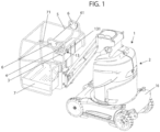
- the subject of the invention is a nacelle 1 which comprises a platform 7 having a location 71 for receiving an operator 30.
- This work platform 7 is here formed of a floor and guardrails surrounding the floor while allowing access to the interior of said platform.
- the operator 30 is generally standing inside the location 71 for receiving the platform 7 and faces a control console 3 carried by the platform 7.
- This control console 3 is generally arranged at a distance from the floor of platform 7 along the guardrail of platform 7 as illustrated in figure 1 .
- This control console 3 is equipped with at least one, preferably several, manually operable controls 4 such as buttons, levers, or others. These commands 4 allow the control of a system 2 for driving the movement of the platform 7.
- This system 2 for driving the movement of the platform 7 can affect a large number of shapes depending on the type of nacelle which can be a suspended nacelle or carried by a mobile chassis as in the example shown in the figure 1 .
- the system 2 for driving the movement of the platform 7 may include a winch on board said nacelle and cables for suspending the nacelle using the winch.
- Platform 7 can still be driven in elevation relative to the carrier chassis 16, as in the example shown in figure 1 , to form a lifting pod 1.
- Chassis 16 is therefore a motorized chassis equipped with wheels or tracks.
- the platform 7 is connected to the chassis 16 by an elevation structure comprising at least one actuator of the elevation structure.
- Actuator and elevation structure form part of the system 2 for driving the movement of the platform 7.
- the elevation structure here comprises at least one arm pivoting around a horizontal axis and the actuator is a cylinder. actuation of said arm extending between the arm and the chassis 16. This arm is preferably a telescopic arm.
- the controls 4 of the control console 3 allow the control of the system 2 for driving movement of the platform 7 by actuation of the motor of the chassis 16 and/or at least one actuator of the elevation structure to allow movement of the platform 7 by movement on the ground of the chassis 16 and/or by movement of the arm.
- This system 2 for driving the movement of the platform 7 will not be described in more detail because it is well known to those skilled in this art.
- the nacelle 1 also includes a flexible safety link 5 which can be made in the form of a cable, a belt, a chain or other.
- the flexible security link 5 is a cable.
- This link 5 has two ends shown at 51 in the figures.
- the nacelle 1 also includes two systems 6 for maintaining the link 5 carried by the platform 7. These systems 6 for maintaining the link are arranged facing each other. These holding systems 6 are here carried by two guardrails each delimiting a vertical side of the floor of the platform 7, said sides being opposite.
- the systems 6 for maintaining the link 5 are arranged, one, at one of the ends, the other, at the other end of the link 5 for maintaining the link 5 in at least one position in which the link 5 extends in the stretched state horizontally or substantially horizontally, that is to say ⁇ 20°.
- the link 5 thus extends substantially parallel to within ⁇ 20° to the support plane of the floor of the platform 7.
- the link 5 extends across the platform 7 by connecting, for example as in the examples shown, two sides opposite verticals of the platform adjoining the floor of the platform.
- this link 5 extends across the platform 7 near the control console 3 on the trajectory that can be followed by a part of the body, in particular the upper part of the body of an operator standing in front of the console 3 of command and leaning towards the control console 3.
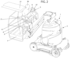
- This link 5 thus forms a demarcation line between part of the location 71 for receiving the operator of the platform 7 and the control console 3 to be able to be requested by the operator as soon as the latter is unbalanced towards the forward, for example under the effect of a push from the back by an obstacle as illustrated in figure 2 .
- link 5 under the effect of pressure exerted by the operator on link 5 causes an increase in the volume of location 71 that can be occupied by the operator on platform 7.
- the link maintenance systems 6 may be identical or different from one maintenance system to another.
- At least one of the holding systems 6 comprises a rotary member 10 for winding the link 5 around which the link 5 coupled to said rotary member 10 partially winds.
- Said rotary member 10 is equipped with at least one elastic return member 11 of said rotary member 10 configured to exert on said rotary member 10 a driving force in angular displacement of the rotary member 10 in the direction of winding of the link 5 around said rotary member 10.
- each holding system 6 comprises a rotating member 10 for winding the link and a member 11 for elastic return of the rotating member 10 for winding the link, these elements each being housed in a fixed housing to the platform.
- the rotating member 10 for winding the link is, preferably, as in the examples shown, a pulley wheel 101 carried by an axis 102 disposed in a stationary manner on the platform.
- the pulley wheel 101 and its axis 102 are housed at least partially inside the housing carried by the platform 7 when the latter is present.
- the wheel 101 rotates around the axis 102.
- This wheel 101 has a rim 103 providing, for example, a groove to receive the part of the link 5 winding around the wheel 101.
- the end 51 of the link is coupled to wheel 101.
- the end 51 of link 5 can be equipped with a cable stop fitting into a housing of wheel 101.
- the elastic return member 11 of the rotary winding member 10 is, for its part, an elastically deformable member which can assume a large number of shapes.
- This return member 11 is produced here in the form of a torsion spring which winds at least partially around the stationary axis 102 of rotation of the wheel 101.
- This spring is a hairpin spring with two branches connected by a spiral winding wrapping around the axis. One of the branches of the spring rests on a fixed stop external to the wheel 101 while the other branch of the spring is coupled to the pulley wheel 101.
- the branches are elastically returned to a spaced position from one another.
- the nacelle 1 comprises a stop 14 for limiting the angular movement of the rotary winding member 10 of the link 5.
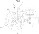
- This stop 14 here affects the shape of a stud 141 circulating in a circular guide path 142 provided on the rotary winding member 10 of the link 5 and with a center radius passing through the axis of rotation of the rotary winding member 10 of the link 5
- This guide path 142 has, in the examples shown, the shape of an elongated curved groove closed at each of its ends and inside which the stud 141 is arranged in the unstressed state of the link 5. extending in the stretched state between the holding systems 6.
- the stud 141 extends in the guide path 142 between the ends of the guide path 142.
- an angular movement of the wheel 101 relative to the stud 141 up to a position in which the stud 141 bears against one end of the guide path 142 provided on the wheel 101 can take place in both directions of movement. driving movement of the wheel 101.
- the stop 14 is therefore configured to limit the angular displacement of the rotary member 10 beyond a predetermined displacement stroke, on the one hand, in the driven state of the rotary member 10 in the clockwise direction, on the other hand, to the driven state of the member 10 rotating in the counterclockwise direction.
- the stop 14 acts as an end stop during deformation of the link by pressure exerted on the link 5 or by release of the link 5 when, for example, the link 5 is broken.
- figures 4 And 5 there Figure 3 illustrating the position of the stud 141 forming the stop 14 in the unloaded state of the link 5.
- the nacelle 1 also comprises a device 8 for detecting a deformation of the link 5.
- This detection device 8 comprises at least one member 9 for detecting a deformation of the link 5.
- This detection member 9 is configured to, under the effect of a deformation of the link 5, to move from a so-called inactive state in which the operation of the command(s) 4 of the system 2 for driving the movement of the platform 7 is not prevented, that is to say -say the manual actuation by the operator of the command(s) 4, allows control of the system 2 for driving movement of the platform to a so-called active state in which the operation of the command(s) 4 is prevented, c that is to say, the manual actuation of the command(s) 4 by the operator has no effect on the control of the system 2 for driving the movement of the platform 7 so that the platform 7 is stopped.
- connection between the detection member 9 and the controls 4 to allow inactivation of the controls 4 in the active state of the detection member 9 can affect a large number of shapes.
- the nacelle includes an emergency stop button 15 fitted to the control console.
- This emergency stop button 15 in the state activated by the operator prevents any power supply in particular to the controls 4 of the control console so that their actuation by the operator has no effect on the movement drive system of platform 7.
- the member 9 for detecting a deformation of the link 5 can behave like an emergency stop button and invalidate the command(s) 4 in a manner similar to what can be provided in terms of inactivation of the command(s) in the case of actuation of the emergency stop button 15.
- the nacelle 1 comprises an electrical circuit for supplying the controls 4 of the control console and the member 9 for detecting a deformation of the link 5 is configured to open/close said electrical circuit as a function of the angular position of the rotating member 10 for winding the link, said controls 4 being inactive in the open state of the circuit.
- the member 9 for detecting a deformation of the link is configured to pass from the inactive state in which it closes the circuit to the active state in which it opens the circuit under the effect of a deformation of the link 5.
- the nacelle 1 comprises a control unit 12 with which the device 8 for detecting a deformation of the link 5 is configured to communicate.
- This control unit 12 is configured to emit a control signal to stop the operation of the controls 4 of the system 2 for driving the movement of the platform 7 as a function of the data received from the detection device 8.
- the nacelle 1 can include a sound and/or light warning device and the control unit 12 can also be configured to emit a warning signal, that is to say a warning signal. visual and/or audible alert depending on the data received from the device 8 for detecting a deformation of the link 5 in a manner known in itself.
- the control unit 12 is an electrical and/or computer system. Said control unit comprises, for example, a processor or controller, or dedicated electronic components or FPGA type components or ASIC. It is also possible to combine computer parts and electronic parts.
- the control unit 12 can be at least partially common with a nacelle computer associated with the control console.
- control unit 12 can be implemented in the form of a computer program or via hardware components (for example programmable gate networks) implemented in, and/or forming part of said unit 12 control.
- Computer programs or computer instructions may be contained in program storage devices, for example computer-readable digital data storage media or executable programs. Programs or instructions can also be executed from program storage devices.
- the member 9 for detecting a deformation of the link 5 is a member for detecting the angular position of the rotating member 10 for winding the link 5 of one of the holding systems 6.
- This member 9 for detecting the angular position of the rotating member 10 for winding the link 5 can affect a large number of shapes.
- This member 9 for detecting the angular position of the rotary member 10 for winding the link 5 can be a sensor 91 for detecting the angular position of the member 10 for winding the link 5 by contact with said rotary member 10 winding of the link 5 as in the example shown where the sensor is of the push-button type with a movable part.
- the mobile part of this sensor is, in the inactive state of the sensor positioned in a notch provided on the external circumference of the wheel 101 of the rotary member 10 for winding the link.
- the angular movement of the wheel 101 causes, by support contact of the edge of the wheel 101 with the movable part formed by the pusher of the sensor and a movement of said movable part of the sensor and the passage of said sensor from an inactive state to a active state in which it can either open the electrical circuit, as described above, or send a signal to the control unit depending on its design.
- the sensor 91 for detecting the angular position of the rotary member 10 for winding the link can be a contactless detection sensor with the rotary winding member 10 of the link 5.
- This sensor can, in this case, be a distance or proximity sensor such as an infrared sensor, an inductive sensor, a capacitive or photo-corrective sensor or other.
- the transition from the inactive state to the active state of said sensor can make it possible to open the electrical circuit as mentioned above or generate the addressing of a signal to the control unit 12.
- this sensor 91 for detecting the angular position of the rotary winding member 10 of the link 5 is electrically connected to the control unit 12 and is configured to send a signal to the control unit 12 electrical as a function at least of the angular position of the rotary member 10 for winding the link 5 around said holding system 6.
- the member 9 for detecting a deformation of the link 5 is configured to, under the effect of a deformation of the link, move from an inactive state to an active state in a position angular position of said rotary winding member 10 of the link other than the or at least one of the angular positions of said rotary winding member 10 of the link 5 corresponding to an end position of said rotary winding member 10 materialized by the stop 14.
- the member 9 for detecting a deformation of the link 5 detects an angular movement of the rotary member 10 and passes from the inactive state to the active state before the member 10 rotating winding of the link can no longer move angularly under the action of the stop 14.
- the scenarios can be numerous.
- an audible or visual alarm can precede the stopping of the movement of the platform 7 by inactivation of the commands 4 or not.
- the alarm can be omitted.
- the detection of an angular displacement of the rotary member 10 for winding the link by the member 9 for detecting a deformation of the link can take place from the start of the angular displacement stroke of the member 10 rotary winding of the link or, for example, in the middle of this angular displacement stroke depending on the desired responsiveness.
- each of the holding systems 6 comprises a rotary member 10 for winding the link around which the link partially winds up, and an elastic return member 11 formed by a spring 111 equipping said rotary member 10.
- the device 8 for detecting a deformation of the link 5 comprising a member 9 for detecting a deformation of the link 5 formed by a member 9 for detecting the angular position of the rotating member 10 for winding the link 5 equips a only one of the holding systems 6 called the main holding system 61.
- the stiffness of the spring 111 fitted to this main holding system 61 is less than the stiffness of the spring 111 fitted to the other holding system 6.
- the nacelle 1 also comprises a system 13 for resetting the operation of the command(s) 4 of the platform movement drive system 2 in the prevented state of the commands 4 from operating, this system 13 comprising a manually operable reset member 131 .
- a nacelle 1 as described above is carried out as follows: the holding systems 6 are fixed to the platform 7 in a position in which the link 5 is in the taut state between the holding systems 6 and forms a substantially horizontal line separating the space placed above the control console 3 and the location 71 for receiving an operator 30 as illustrated in figure 1 . In this position, the link 5 is held taut under the action of the elastic return members 11.
- the stop 14 is, in particular the stud 141 constituting said stop, is arranged between the ends of the guide path 142 provided on the rotary winding member 10 of the link 5 so that the rotating winding member 10 can be moved angularly clockwise or counterclockwise.
- the member 9 for detecting a deformation of the link 5 by detecting the angular position of the rotating member 10 for winding the link is in the inactive state.
- the movable part of the push-button is housed in the notch provided on the periphery of the wheel 101 constituting the rotating winding member 10 of link 5 as described above.
- the link 5 Under the effect of pressure applied to the link 5 and resulting from a movement of the operator towards the control console 3, the link 5 is generally deformed in the direction of an increase in the volume of the location 71 for receiving the operator 30. This deformation of the link by pressure on the link 5 causes an angular displacement of the rotary winding members 10 of the link 5 against the action of the elastic return members 11 in the direction of an unwinding of the link 5 of said rotary winding members 10 of the link 5.
- the periphery of the rotary member 10 for winding the link in contact with the movable part of the member 9 for detecting a deformation of the link is no longer formed by the hollow of the notch but by the edges of the notch.
- the movement of this mobile part of the detection member 9 corresponds to the passage of said member 9 for detecting a deformation of the link from an inactive state to an active state.
- This activation is detected by the control unit 12 which emits a control signal to stop the operation of the controls 4 of the system 2 for driving the movement of the platform 7 and therefore a stop in movement of the platform 7.
- a warning device when present, may be activated and an alarm may be issued.
- the movement of the platform 7 is stopped before the rotating member 10 for winding the link 5 is in the end position relative to the stop 14. It is then possible for the operator to exercise additional pressure on the link 5 to generate an additional angular displacement of the rotary winding members 10 of the link and to clear a space between, for example, an obstacle 31 which would push it in the back and the link 5. The operator can then activate the reset member 131 and order movement of the platform again. This command allows the operator to release itself from the link. Once link 5 is released from all pressure the operator, this link 5 returns to its initial position and normal operation of the nacelle can resume.
Landscapes
- Engineering & Computer Science (AREA)
- Structural Engineering (AREA)
- Life Sciences & Earth Sciences (AREA)
- Geology (AREA)
- Mechanical Engineering (AREA)
- Invalid Beds And Related Equipment (AREA)
- Forklifts And Lifting Vehicles (AREA)
- Wind Motors (AREA)
- Platform Screen Doors And Railroad Systems (AREA)
Claims (10)
- Korb (1), umfassend:- eine Plattform (7), die eine Aufnahmestelle (71) für einen Bediener (30) aufweist,- ein Antriebssystem (2) zur Verlagerung der Plattform (7),- ein von der Plattform (7) getragenes Steuerpult (3), das mit mindestens einer manuell bedienbaren Steuerung (4) des Antriebssystems (2) zur Verlagerung der Plattform (7) ausgestattet ist,- eine flexible Sicherheitsleine (5),- zwei Haltesysteme (6) der Leine (5), von denen eins an einem der Enden (51) der Leine (5) und das andere am anderen der Enden (51) der Leine (5) zum Halten der Leine (5) in mindestens einer Position angeordnet ist, in welcher sich die Leine (5) durch die Plattform erstreckt und eine Demarkationslinie zwischen einem Abschnitt der Aufnahmestelle (71) für einen Bediener der Plattform (7) und dem Steuerpult (3) bildet,- eine Detektionsvorrichtung (8) einer Verformung der Leine (5), umfassend mindestens ein Detektionsorgan (9) einer Verformung der Leine (5), wobei das Detektionsorgan (9) dazu ausgelegt ist, unter der Wirkung einer Verformung der Leine (5) aus einem als inaktiv bezeichneten Zustand, in welchem der Betrieb der Steuerung(en) (4) des Antriebssystems (2) zur Verlagerung der Plattform (7) nicht verhindert ist, in einen als aktiv bezeichneten Zustand, in welchem die Betrieb der Steuerung(en) (4) verhindert ist, zu wechseln, dadurch gekennzeichnet, dass mindestens eins, vorzugsweise jedes der Haltesysteme (6) ein rotierendes Wickelorgan (10) der Leine (5) umfasst, um das sich die Leine (5), die an das rotierende Organ (10) gekoppelt ist, teilweise wickelt, wobei das rotierende Organ (10) mit mindestens einem elastischen Rückstellorgan (11) des rotierenden Organs (10) ausgestattet ist, das dazu ausgelegt ist, auf das rotierende Organ (10) eine Antriebskraft zwecks Winkelverlagerung des rotierenden Organs (10) im Hinblick auf ein Wickeln der Leine (5) um das rotierende Organ (10) auszuüben.
- Korb (1) nach Anspruch 1, dadurch gekennzeichnet, dass das oder mindestens eins der Detektionsorgane (9) einer Verformung der Leine (5) ein Detektionsorgan der Winkelposition des rotierenden Wickelorgans (10) der Leine (5) eines der Haltesysteme (6) ist.
- Korb (1) nach einem der Ansprüche 1 oder 2, dadurch gekennzeichnet, dass der Korb (1) eine Steuereinheit (12) umfasst, mit welcher die Detektionsvorrichtung (8) einer Verformung der Leine (5) ausgelegt ist zu kommunizieren, wobei diese Steuereinheit (12) dazu ausgelegt ist, ein Steuersignal zum Stoppen des Betriebs der Steuerungen (4) des Antriebssystems (2) zur Verlagerung der Plattform (7) in Abhängigkeit von den von der Detektionsvorrichtung (8) empfangenen Daten zu senden.
- Korb (1) nach Anspruch 3, dadurch gekennzeichnet, dass das oder mindestens eins der Detektionsorgane (9) einer Verformung der Leine (5) ein Sensor (91) zur Detektion der Winkelposition des rotierenden Wickelorgans (10) der Leine (5) eines der Haltesysteme (6) durch Kontakt mit dem rotierenden Wickelorgan (10) der Leine (5) oder ohne Kontakt ist, wobei dieser Sensor (91) mit der Steuereinheit (12) elektrisch verbunden und dazu ausgelegt ist, der Steuereinheit (12) ein elektrisches Signal in Abhängigkeit von mindestens der Winkelposition des rotierenden Wickelorgans (10) der Leine (5) des Haltesystems (6) zu senden.
- Korb (1) nach einem der Ansprüche 1 bis 4, dadurch gekennzeichnet, dass der Korb (1) ein Reinitialisierungssystem (13) des Betriebs der Steuerung(en) des Antriebssystems zur Verlagerung der Plattform im verhinderten Betriebszustand der Steuerungen (4) umfasst, wobei dieses System (13) ein manuell betätigbares Reinitialisierungsorgan (131) umfasst.
- Korb (1) nach einem der Ansprüche 1 bis 5, dadurch gekennzeichnet, dass das rotierende Wickelorgan (10) der Leine (5) eines der Haltesysteme (6) ein Riemenscheibenrad (101) ist, das von einer Welle (102) getragen wird, die stationär auf der Plattform (7) angeordnet ist, wobei das Riemenscheibenrad (101) eine Felge (103) aufweist, die dazu ausgelegt ist, die Leine (5) zu empfangen, die mit einem ihrer Enden (51) am Rad (101) gekoppelt ist und dass das elastische Rückstellorgan (11) des rotierendes Wickelorgans (10) eine Feder, vorzugsweise eine Torsionsfeder ist.
- Korb (1) nach einem der Ansprüche 1 bis 6, dadurch gekennzeichnet, dass der Korb (1) einen Begrenzungsanschlag (14) der Winkelverlagerung des rotierenden Wickelorgans (10) der Leine (5) eines der Haltesysteme (6) umfasst, wobei der Anschlag (14) dazu ausgelegt ist, die Winkelverlagerung des rotierenden Organs (10) über einen vorher festgelegten Verlagerungsweg zum einen im angetriebenen Zustand des rotierenden Organs (10) in Uhrzeigerrichtung, zum anderen im angetriebenen Zustand des rotierenden Organs (10) entgegen der Uhrzeigerrichtung zu begrenzen.
- Korb (1) nach einem der Ansprüche 1 bis 7, dadurch gekennzeichnet, dass der Korb (1) einen Begrenzungsanschlag (14) der Winkelverlagerung des rotierenden Wickelorgans (10) der Leine (5) eines der Haltesysteme (6) umfasst, wobei der Anschlag (14) dazu ausgelegt ist, die Winkelverlagerung des rotierenden Organs (10) mindestens in Richtung eines Abwickelns der Leine des rotierenden Organs (10) über einen vorher festgelegten Winkelverlagerungsweg des rotierenden Organs (10) hinaus zu begrenzen, wobei das Detektionsorgan (9) einer Verformung der Leine (5) dazu ausgelegt ist, unter der Wirkung einer Verformung der Leine (5) aus einem inaktiven Zustand in einen aktiven Zustand in eine Winkelposition des rotierenden Wickelorgans (10) der Leine (5) zu wechseln, die eine andere als die oder mindestens eine der Winkelpositionen des rotierenden Wickelorgans (10) der Leine ist, die einer Endlagenposition des rotierenden Wickelorgans (10) entspricht, die durch den Anschlag (14) materialisiert ist.
- Korb (1) nach einem der Ansprüche 1 bis 8, dadurch gekennzeichnet, dass jedes der Haltesysteme (6) ein rotierendes Wickelorgan (10) der Leine (5) umfasst, um das sich die Leine teilweise wickelt, und ein elastisches Rückstellorgan (11), gebildet von einer Feder (111), die das rotierende Organ (10) ausstattet, und die Detektionsvorrichtung (8) einer Verformung der Leine (5) ein Detektionsorgan (9) einer Verformung der Leine (5) umfasst, das von einem Detektionsorgan der Winkelposition des rotierenden Wickelorgans (10) der Leine (5) eines einzigen der Haltesysteme (6), bezeichnet als Haupthaltesystem (61), gebildet ist, wobei die Steifigkeit der Feder (111), die dieses Haupthaltesystem (61) ausstattet, geringer ist als die Steifigkeit der Feder (111), die das andere Haltesystem (6) ausstattet.
- Korb (1) nach einem der Ansprüche 1 bis 9, dadurch gekennzeichnet, dass der Korb (1) ein Hubkorb ist.
Applications Claiming Priority (2)
| Application Number | Priority Date | Filing Date | Title |
|---|---|---|---|
| FR1910232A FR3100805B1 (fr) | 2019-09-17 | 2019-09-17 | Nacelle, notamment nacelle élévatrice |
| PCT/FR2020/051472 WO2021053280A1 (fr) | 2019-09-17 | 2020-08-17 | Nacelle, notamment nacelle élévatrice |
Publications (2)
| Publication Number | Publication Date |
|---|---|
| EP4031477A1 EP4031477A1 (de) | 2022-07-27 |
| EP4031477B1 true EP4031477B1 (de) | 2023-10-04 |
Family
ID=68733382
Family Applications (1)
| Application Number | Title | Priority Date | Filing Date |
|---|---|---|---|
| EP20772365.1A Active EP4031477B1 (de) | 2019-09-17 | 2020-08-17 | Korb-, insbesondere luftkorbhubvorrichtung |
Country Status (9)
| Country | Link |
|---|---|
| US (1) | US12486152B2 (de) |
| EP (1) | EP4031477B1 (de) |
| CN (1) | CN114401919B (de) |
| AU (1) | AU2020349066B2 (de) |
| CA (1) | CA3149948C (de) |
| FR (1) | FR3100805B1 (de) |
| HU (1) | HUE064838T2 (de) |
| PL (1) | PL4031477T3 (de) |
| WO (1) | WO2021053280A1 (de) |
Families Citing this family (2)
| Publication number | Priority date | Publication date | Assignee | Title |
|---|---|---|---|---|
| EP3848327A4 (de) * | 2019-09-30 | 2023-03-01 | Zoomlion Intelligent Access Machinery Co., Ltd. | Extrusionsschutzvorrichtung für bewegliche arbeitsplattform, druckstangen-extrusionsschutzvorrichtung und maschine mit betrieb in grosser höhe |
| CN117509491A (zh) * | 2023-10-23 | 2024-02-06 | 浙江鼎力机械股份有限公司 | 一种行走式高空作业平台 |
Family Cites Families (14)
| Publication number | Priority date | Publication date | Assignee | Title |
|---|---|---|---|---|
| US4979588A (en) * | 1990-02-12 | 1990-12-25 | Kidde Industries, Inc. | Overhead impact sensing system |
| JPH0465299A (ja) | 1990-07-06 | 1992-03-02 | Toshiba Corp | クリップの取付構造 |
| JPH0465299U (de) * | 1990-10-18 | 1992-06-05 | ||
| US10358331B2 (en) * | 2010-12-20 | 2019-07-23 | Jlg Industries, Inc. | Work platform with protection against sustained involuntary operation |
| FR2909084B1 (fr) | 2006-11-29 | 2009-02-13 | Haulotte Group Sa | Nacelle elevatrice, procede de commande et support d'enregistrement pour cette nacelle. |
| GB2457908A (en) | 2008-02-28 | 2009-09-02 | Blue Sky Access Ltd | A safety device for an aerial lift |
| GB201011136D0 (en) * | 2010-07-02 | 2010-08-18 | Blue Sky Access Ltd | An aerial lift with safety device |
| GB2497803B (en) | 2011-12-21 | 2014-12-03 | Bluesky Solutions Ltd | Aerial lift with safety device and alarm |
| FR3007401B1 (fr) * | 2013-06-25 | 2015-07-03 | Haulotte Group | Nacelle elevatrice a pupitre de commande securise |
| FR3008404B1 (fr) * | 2013-07-10 | 2015-08-07 | Haulotte Group | Plateforme de nacelle elevatrice et nacelle elevatrice equipee d'une telle plateforme |
| JP6612101B2 (ja) * | 2015-10-13 | 2019-11-27 | 株式会社アイチコーポレーション | 高所作業車の安全装置 |
| US10549975B2 (en) * | 2016-11-14 | 2020-02-04 | Terex South Dakota, Inc. | Safety device for mobile work platforms |
| CN108358136B (zh) * | 2018-05-14 | 2024-02-27 | 浙江鼎力机械股份有限公司 | 工作平台防挤压系统、高空作业平台及控制方法 |
| CN108751070A (zh) * | 2018-06-28 | 2018-11-06 | 艾陌极智能装备(深圳)有限公司 | 智能高空作业吊篮副绳检测器 |
-
2019
- 2019-09-17 FR FR1910232A patent/FR3100805B1/fr not_active Expired - Fee Related
-
2020
- 2020-08-17 CA CA3149948A patent/CA3149948C/fr active Active
- 2020-08-17 CN CN202080064912.9A patent/CN114401919B/zh active Active
- 2020-08-17 US US17/761,168 patent/US12486152B2/en active Active
- 2020-08-17 AU AU2020349066A patent/AU2020349066B2/en active Active
- 2020-08-17 EP EP20772365.1A patent/EP4031477B1/de active Active
- 2020-08-17 HU HUE20772365A patent/HUE064838T2/hu unknown
- 2020-08-17 PL PL20772365.1T patent/PL4031477T3/pl unknown
- 2020-08-17 WO PCT/FR2020/051472 patent/WO2021053280A1/fr not_active Ceased
Also Published As
| Publication number | Publication date |
|---|---|
| PL4031477T3 (pl) | 2024-03-11 |
| CN114401919B (zh) | 2023-09-08 |
| AU2020349066A1 (en) | 2022-03-24 |
| FR3100805B1 (fr) | 2021-08-13 |
| US12486152B2 (en) | 2025-12-02 |
| AU2020349066B2 (en) | 2025-06-05 |
| US20220371870A1 (en) | 2022-11-24 |
| EP4031477A1 (de) | 2022-07-27 |
| HUE064838T2 (hu) | 2024-04-28 |
| CA3149948C (fr) | 2025-05-13 |
| CA3149948A1 (fr) | 2021-03-25 |
| FR3100805A1 (fr) | 2021-03-19 |
| WO2021053280A1 (fr) | 2021-03-25 |
| CN114401919A (zh) | 2022-04-26 |
Similar Documents
| Publication | Publication Date | Title |
|---|---|---|
| EP2616616B1 (de) | Kraftfahrzeugsgriff mit einem trägheitskörper und einer sicherung | |
| EP4031477B1 (de) | Korb-, insbesondere luftkorbhubvorrichtung | |
| EP3299248B1 (de) | Erkennungsvorrichtung eines hindernisses für schienenfahrzeug | |
| EP3962844B1 (de) | Vorrichtung zum blockieren eines fahrzeugs vor einer ladebrücke | |
| EP0046427A1 (de) | Bindeeinrichtung für Rundballenpressen | |
| LU92819B1 (fr) | Dispositif de sécurité autobloquant pour corde d'escalade | |
| EP2556768A2 (de) | Koffer mit Bremse | |
| FR2947254A1 (fr) | Perfectionnement a un dispositif de securite pour porte d'ascenseur | |
| EP0819204A1 (de) | Hubtor mit sicherheitssystem | |
| EP4640501A1 (de) | Stossfängersystem für ein rad einer landwirtschaftlichen maschine | |
| FR2848545A1 (fr) | Dispositif de vissage de bouchons | |
| FR2885158A1 (fr) | Vehicule avec un hayon | |
| EP1790211B1 (de) | Vorschneidemaschine mit integrierten Ausweichmitteln für Pfähle oder ähnliches | |
| EP4399174B1 (de) | Hubarbeitsbühne zur höhenbearbeitung, steuerungsverfahren und anordnung mit einer solchen hubarbeitsbühne | |
| EP4134295B1 (de) | Selbstausbalancierendes fahrzeug mit anti-kippvorrichtung | |
| EP0057122B1 (de) | Bindevorrichtung für Rundballenpressen | |
| EP4385933A1 (de) | Verfahren zum schutz eines hebezeuges gegen überlast und vorrichtung zur durchführung des verfahrens | |
| EP1680962B1 (de) | Elektrisches Gerät zum Verarbeiten von Lebensmitteln mit verbesserter Sicherheit | |
| EP4448438A1 (de) | Schaufel, insbesondere luftschaufel | |
| EP1992320B1 (de) | Verschiebbares Möbelstück mit Antriebs- und Steuerrad | |
| FR2888554A1 (fr) | Dispositif de maintien en position de la porte d'un vehicule automobile en cas de choc frontal | |
| FR2886247A1 (fr) | Dispositif de protection des pietons en cas de choc frontal avec un vehicule automobile, vehicule automobile equipe d'un tel dispositif de protection des pietons | |
| EP0064113A1 (de) | Binderbetätigungseinrichtung für Rundballenpresse | |
| FR2773665A1 (fr) | Dispositif de secouage pour la recolte de fruits portes par des arbres ou arbustes, et ensemble-recepteur de fruits equipe d'un tel dispositif de secouage | |
| EP1338484A1 (de) | Aufprallschutzsystem für Fussgänger und damit ausgestattetes Fahrzeug |
Legal Events
| Date | Code | Title | Description |
|---|---|---|---|
| STAA | Information on the status of an ep patent application or granted ep patent |
Free format text: STATUS: UNKNOWN |
|
| STAA | Information on the status of an ep patent application or granted ep patent |
Free format text: STATUS: THE INTERNATIONAL PUBLICATION HAS BEEN MADE |
|
| PUAI | Public reference made under article 153(3) epc to a published international application that has entered the european phase |
Free format text: ORIGINAL CODE: 0009012 |
|
| STAA | Information on the status of an ep patent application or granted ep patent |
Free format text: STATUS: REQUEST FOR EXAMINATION WAS MADE |
|
| 17P | Request for examination filed |
Effective date: 20220322 |
|
| AK | Designated contracting states |
Kind code of ref document: A1 Designated state(s): AL AT BE BG CH CY CZ DE DK EE ES FI FR GB GR HR HU IE IS IT LI LT LU LV MC MK MT NL NO PL PT RO RS SE SI SK SM TR |
|
| DAV | Request for validation of the european patent (deleted) | ||
| DAX | Request for extension of the european patent (deleted) | ||
| GRAP | Despatch of communication of intention to grant a patent |
Free format text: ORIGINAL CODE: EPIDOSNIGR1 |
|
| STAA | Information on the status of an ep patent application or granted ep patent |
Free format text: STATUS: GRANT OF PATENT IS INTENDED |
|
| INTG | Intention to grant announced |
Effective date: 20230503 |
|
| GRAS | Grant fee paid |
Free format text: ORIGINAL CODE: EPIDOSNIGR3 |
|
| P01 | Opt-out of the competence of the unified patent court (upc) registered |
Effective date: 20230621 |
|
| GRAA | (expected) grant |
Free format text: ORIGINAL CODE: 0009210 |
|
| STAA | Information on the status of an ep patent application or granted ep patent |
Free format text: STATUS: THE PATENT HAS BEEN GRANTED |
|
| AK | Designated contracting states |
Kind code of ref document: B1 Designated state(s): AL AT BE BG CH CY CZ DE DK EE ES FI FR GB GR HR HU IE IS IT LI LT LU LV MC MK MT NL NO PL PT RO RS SE SI SK SM TR |
|
| REG | Reference to a national code |
Ref country code: GB Ref legal event code: FG4D Free format text: NOT ENGLISH |
|
| REG | Reference to a national code |
Ref country code: CH Ref legal event code: EP |
|
| REG | Reference to a national code |
Ref country code: IE Ref legal event code: FG4D Free format text: LANGUAGE OF EP DOCUMENT: FRENCH |
|
| REG | Reference to a national code |
Ref country code: DE Ref legal event code: R096 Ref document number: 602020018730 Country of ref document: DE |
|
| REG | Reference to a national code |
Ref country code: NL Ref legal event code: FP |
|
| REG | Reference to a national code |
Ref country code: LT Ref legal event code: MG9D |
|
| REG | Reference to a national code |
Ref country code: AT Ref legal event code: MK05 Ref document number: 1617608 Country of ref document: AT Kind code of ref document: T Effective date: 20231004 |
|
| PG25 | Lapsed in a contracting state [announced via postgrant information from national office to epo] |
Ref country code: GR Free format text: LAPSE BECAUSE OF FAILURE TO SUBMIT A TRANSLATION OF THE DESCRIPTION OR TO PAY THE FEE WITHIN THE PRESCRIBED TIME-LIMIT Effective date: 20240105 |
|
| PG25 | Lapsed in a contracting state [announced via postgrant information from national office to epo] |
Ref country code: IS Free format text: LAPSE BECAUSE OF FAILURE TO SUBMIT A TRANSLATION OF THE DESCRIPTION OR TO PAY THE FEE WITHIN THE PRESCRIBED TIME-LIMIT Effective date: 20240204 |
|
| PG25 | Lapsed in a contracting state [announced via postgrant information from national office to epo] |
Ref country code: LT Free format text: LAPSE BECAUSE OF FAILURE TO SUBMIT A TRANSLATION OF THE DESCRIPTION OR TO PAY THE FEE WITHIN THE PRESCRIBED TIME-LIMIT Effective date: 20231004 |
|
| PG25 | Lapsed in a contracting state [announced via postgrant information from national office to epo] |
Ref country code: AT Free format text: LAPSE BECAUSE OF FAILURE TO SUBMIT A TRANSLATION OF THE DESCRIPTION OR TO PAY THE FEE WITHIN THE PRESCRIBED TIME-LIMIT Effective date: 20231004 |
|
| PG25 | Lapsed in a contracting state [announced via postgrant information from national office to epo] |
Ref country code: ES Free format text: LAPSE BECAUSE OF FAILURE TO SUBMIT A TRANSLATION OF THE DESCRIPTION OR TO PAY THE FEE WITHIN THE PRESCRIBED TIME-LIMIT Effective date: 20231004 |
|
| REG | Reference to a national code |
Ref country code: HU Ref legal event code: AG4A Ref document number: E064838 Country of ref document: HU |
|
| PG25 | Lapsed in a contracting state [announced via postgrant information from national office to epo] |
Ref country code: LT Free format text: LAPSE BECAUSE OF FAILURE TO SUBMIT A TRANSLATION OF THE DESCRIPTION OR TO PAY THE FEE WITHIN THE PRESCRIBED TIME-LIMIT Effective date: 20231004 Ref country code: IS Free format text: LAPSE BECAUSE OF FAILURE TO SUBMIT A TRANSLATION OF THE DESCRIPTION OR TO PAY THE FEE WITHIN THE PRESCRIBED TIME-LIMIT Effective date: 20240204 Ref country code: GR Free format text: LAPSE BECAUSE OF FAILURE TO SUBMIT A TRANSLATION OF THE DESCRIPTION OR TO PAY THE FEE WITHIN THE PRESCRIBED TIME-LIMIT Effective date: 20240105 Ref country code: ES Free format text: LAPSE BECAUSE OF FAILURE TO SUBMIT A TRANSLATION OF THE DESCRIPTION OR TO PAY THE FEE WITHIN THE PRESCRIBED TIME-LIMIT Effective date: 20231004 Ref country code: BG Free format text: LAPSE BECAUSE OF FAILURE TO SUBMIT A TRANSLATION OF THE DESCRIPTION OR TO PAY THE FEE WITHIN THE PRESCRIBED TIME-LIMIT Effective date: 20240104 Ref country code: AT Free format text: LAPSE BECAUSE OF FAILURE TO SUBMIT A TRANSLATION OF THE DESCRIPTION OR TO PAY THE FEE WITHIN THE PRESCRIBED TIME-LIMIT Effective date: 20231004 Ref country code: PT Free format text: LAPSE BECAUSE OF FAILURE TO SUBMIT A TRANSLATION OF THE DESCRIPTION OR TO PAY THE FEE WITHIN THE PRESCRIBED TIME-LIMIT Effective date: 20240205 |
|
| PG25 | Lapsed in a contracting state [announced via postgrant information from national office to epo] |
Ref country code: SE Free format text: LAPSE BECAUSE OF FAILURE TO SUBMIT A TRANSLATION OF THE DESCRIPTION OR TO PAY THE FEE WITHIN THE PRESCRIBED TIME-LIMIT Effective date: 20231004 Ref country code: RS Free format text: LAPSE BECAUSE OF FAILURE TO SUBMIT A TRANSLATION OF THE DESCRIPTION OR TO PAY THE FEE WITHIN THE PRESCRIBED TIME-LIMIT Effective date: 20231004 Ref country code: NO Free format text: LAPSE BECAUSE OF FAILURE TO SUBMIT A TRANSLATION OF THE DESCRIPTION OR TO PAY THE FEE WITHIN THE PRESCRIBED TIME-LIMIT Effective date: 20240104 Ref country code: LV Free format text: LAPSE BECAUSE OF FAILURE TO SUBMIT A TRANSLATION OF THE DESCRIPTION OR TO PAY THE FEE WITHIN THE PRESCRIBED TIME-LIMIT Effective date: 20231004 Ref country code: HR Free format text: LAPSE BECAUSE OF FAILURE TO SUBMIT A TRANSLATION OF THE DESCRIPTION OR TO PAY THE FEE WITHIN THE PRESCRIBED TIME-LIMIT Effective date: 20231004 |
|
| REG | Reference to a national code |
Ref country code: DE Ref legal event code: R097 Ref document number: 602020018730 Country of ref document: DE |
|
| PG25 | Lapsed in a contracting state [announced via postgrant information from national office to epo] |
Ref country code: DK Free format text: LAPSE BECAUSE OF FAILURE TO SUBMIT A TRANSLATION OF THE DESCRIPTION OR TO PAY THE FEE WITHIN THE PRESCRIBED TIME-LIMIT Effective date: 20231004 |
|
| PG25 | Lapsed in a contracting state [announced via postgrant information from national office to epo] |
Ref country code: CZ Free format text: LAPSE BECAUSE OF FAILURE TO SUBMIT A TRANSLATION OF THE DESCRIPTION OR TO PAY THE FEE WITHIN THE PRESCRIBED TIME-LIMIT Effective date: 20231004 |
|
| PG25 | Lapsed in a contracting state [announced via postgrant information from national office to epo] |
Ref country code: SK Free format text: LAPSE BECAUSE OF FAILURE TO SUBMIT A TRANSLATION OF THE DESCRIPTION OR TO PAY THE FEE WITHIN THE PRESCRIBED TIME-LIMIT Effective date: 20231004 |
|
| PG25 | Lapsed in a contracting state [announced via postgrant information from national office to epo] |
Ref country code: SM Free format text: LAPSE BECAUSE OF FAILURE TO SUBMIT A TRANSLATION OF THE DESCRIPTION OR TO PAY THE FEE WITHIN THE PRESCRIBED TIME-LIMIT Effective date: 20231004 Ref country code: SK Free format text: LAPSE BECAUSE OF FAILURE TO SUBMIT A TRANSLATION OF THE DESCRIPTION OR TO PAY THE FEE WITHIN THE PRESCRIBED TIME-LIMIT Effective date: 20231004 Ref country code: RO Free format text: LAPSE BECAUSE OF FAILURE TO SUBMIT A TRANSLATION OF THE DESCRIPTION OR TO PAY THE FEE WITHIN THE PRESCRIBED TIME-LIMIT Effective date: 20231004 Ref country code: EE Free format text: LAPSE BECAUSE OF FAILURE TO SUBMIT A TRANSLATION OF THE DESCRIPTION OR TO PAY THE FEE WITHIN THE PRESCRIBED TIME-LIMIT Effective date: 20231004 Ref country code: DK Free format text: LAPSE BECAUSE OF FAILURE TO SUBMIT A TRANSLATION OF THE DESCRIPTION OR TO PAY THE FEE WITHIN THE PRESCRIBED TIME-LIMIT Effective date: 20231004 Ref country code: CZ Free format text: LAPSE BECAUSE OF FAILURE TO SUBMIT A TRANSLATION OF THE DESCRIPTION OR TO PAY THE FEE WITHIN THE PRESCRIBED TIME-LIMIT Effective date: 20231004 |
|
| PLBE | No opposition filed within time limit |
Free format text: ORIGINAL CODE: 0009261 |
|
| STAA | Information on the status of an ep patent application or granted ep patent |
Free format text: STATUS: NO OPPOSITION FILED WITHIN TIME LIMIT |
|
| 26N | No opposition filed |
Effective date: 20240705 |
|
| PG25 | Lapsed in a contracting state [announced via postgrant information from national office to epo] |
Ref country code: SI Free format text: LAPSE BECAUSE OF FAILURE TO SUBMIT A TRANSLATION OF THE DESCRIPTION OR TO PAY THE FEE WITHIN THE PRESCRIBED TIME-LIMIT Effective date: 20231004 |
|
| PG25 | Lapsed in a contracting state [announced via postgrant information from national office to epo] |
Ref country code: SI Free format text: LAPSE BECAUSE OF FAILURE TO SUBMIT A TRANSLATION OF THE DESCRIPTION OR TO PAY THE FEE WITHIN THE PRESCRIBED TIME-LIMIT Effective date: 20231004 |
|
| REG | Reference to a national code |
Ref country code: CH Ref legal event code: PL |
|
| PG25 | Lapsed in a contracting state [announced via postgrant information from national office to epo] |
Ref country code: LU Free format text: LAPSE BECAUSE OF NON-PAYMENT OF DUE FEES Effective date: 20240817 |
|
| PG25 | Lapsed in a contracting state [announced via postgrant information from national office to epo] |
Ref country code: MC Free format text: LAPSE BECAUSE OF FAILURE TO SUBMIT A TRANSLATION OF THE DESCRIPTION OR TO PAY THE FEE WITHIN THE PRESCRIBED TIME-LIMIT Effective date: 20231004 Ref country code: CH Free format text: LAPSE BECAUSE OF NON-PAYMENT OF DUE FEES Effective date: 20240831 |
|
| REG | Reference to a national code |
Ref country code: BE Ref legal event code: MM Effective date: 20240831 |
|
| PG25 | Lapsed in a contracting state [announced via postgrant information from national office to epo] |
Ref country code: BE Free format text: LAPSE BECAUSE OF NON-PAYMENT OF DUE FEES Effective date: 20240831 |
|
| PG25 | Lapsed in a contracting state [announced via postgrant information from national office to epo] |
Ref country code: IE Free format text: LAPSE BECAUSE OF NON-PAYMENT OF DUE FEES Effective date: 20240817 |
|
| PGFP | Annual fee paid to national office [announced via postgrant information from national office to epo] |
Ref country code: NL Payment date: 20250821 Year of fee payment: 6 |
|
| PGFP | Annual fee paid to national office [announced via postgrant information from national office to epo] |
Ref country code: HU Payment date: 20250825 Year of fee payment: 6 |
|
| PG25 | Lapsed in a contracting state [announced via postgrant information from national office to epo] |
Ref country code: FI Free format text: LAPSE BECAUSE OF FAILURE TO SUBMIT A TRANSLATION OF THE DESCRIPTION OR TO PAY THE FEE WITHIN THE PRESCRIBED TIME-LIMIT Effective date: 20231004 |
|
| PGFP | Annual fee paid to national office [announced via postgrant information from national office to epo] |
Ref country code: DE Payment date: 20250820 Year of fee payment: 6 |
|
| PGFP | Annual fee paid to national office [announced via postgrant information from national office to epo] |
Ref country code: PL Payment date: 20250807 Year of fee payment: 6 Ref country code: IT Payment date: 20250825 Year of fee payment: 6 |
|
| PGFP | Annual fee paid to national office [announced via postgrant information from national office to epo] |
Ref country code: GB Payment date: 20250820 Year of fee payment: 6 |
|
| PGFP | Annual fee paid to national office [announced via postgrant information from national office to epo] |
Ref country code: FR Payment date: 20250828 Year of fee payment: 6 |
|
| PG25 | Lapsed in a contracting state [announced via postgrant information from national office to epo] |
Ref country code: CY Free format text: LAPSE BECAUSE OF FAILURE TO SUBMIT A TRANSLATION OF THE DESCRIPTION OR TO PAY THE FEE WITHIN THE PRESCRIBED TIME-LIMIT; INVALID AB INITIO Effective date: 20200817 |