EP4031765B1 - Fixiermittel für schwere getriebeteile - Google Patents
Fixiermittel für schwere getriebeteile Download PDFInfo
- Publication number
- EP4031765B1 EP4031765B1 EP20765210.8A EP20765210A EP4031765B1 EP 4031765 B1 EP4031765 B1 EP 4031765B1 EP 20765210 A EP20765210 A EP 20765210A EP 4031765 B1 EP4031765 B1 EP 4031765B1
- Authority
- EP
- European Patent Office
- Prior art keywords
- bolt
- hole
- internal thread
- fastening means
- screw
- Prior art date
- Legal status (The legal status is an assumption and is not a legal conclusion. Google has not performed a legal analysis and makes no representation as to the accuracy of the status listed.)
- Active
Links
Images

Classifications
-
- F—MECHANICAL ENGINEERING; LIGHTING; HEATING; WEAPONS; BLASTING
- F16—ENGINEERING ELEMENTS AND UNITS; GENERAL MEASURES FOR PRODUCING AND MAINTAINING EFFECTIVE FUNCTIONING OF MACHINES OR INSTALLATIONS; THERMAL INSULATION IN GENERAL
- F16B—DEVICES FOR FASTENING OR SECURING CONSTRUCTIONAL ELEMENTS OR MACHINE PARTS TOGETHER, e.g. NAILS, BOLTS, CIRCLIPS, CLAMPS, CLIPS OR WEDGES; JOINTS OR JOINTING
- F16B19/00—Bolts without screw-thread; Pins, including deformable elements; Rivets
- F16B19/02—Bolts or sleeves for positioning of machine parts, e.g. notched taper pins, fitting pins, sleeves, eccentric positioning rings
-
- F—MECHANICAL ENGINEERING; LIGHTING; HEATING; WEAPONS; BLASTING
- F03—MACHINES OR ENGINES FOR LIQUIDS; WIND, SPRING, OR WEIGHT MOTORS; PRODUCING MECHANICAL POWER OR A REACTIVE PROPULSIVE THRUST, NOT OTHERWISE PROVIDED FOR
- F03D—WIND MOTORS
- F03D80/00—Details, components or accessories not provided for in groups F03D1/00 - F03D17/00
- F03D80/50—Maintenance or repair
-
- F—MECHANICAL ENGINEERING; LIGHTING; HEATING; WEAPONS; BLASTING
- F16—ENGINEERING ELEMENTS AND UNITS; GENERAL MEASURES FOR PRODUCING AND MAINTAINING EFFECTIVE FUNCTIONING OF MACHINES OR INSTALLATIONS; THERMAL INSULATION IN GENERAL
- F16B—DEVICES FOR FASTENING OR SECURING CONSTRUCTIONAL ELEMENTS OR MACHINE PARTS TOGETHER, e.g. NAILS, BOLTS, CIRCLIPS, CLAMPS, CLIPS OR WEDGES; JOINTS OR JOINTING
- F16B13/00—Dowels or other devices fastened in walls or the like by inserting them in holes made therein for that purpose
- F16B13/04—Dowels or other devices fastened in walls or the like by inserting them in holes made therein for that purpose with parts gripping in the hole or behind the reverse side of the wall after inserting from the front
-
- F—MECHANICAL ENGINEERING; LIGHTING; HEATING; WEAPONS; BLASTING
- F16—ENGINEERING ELEMENTS AND UNITS; GENERAL MEASURES FOR PRODUCING AND MAINTAINING EFFECTIVE FUNCTIONING OF MACHINES OR INSTALLATIONS; THERMAL INSULATION IN GENERAL
- F16H—GEARING
- F16H57/00—General details of gearing
-
- F—MECHANICAL ENGINEERING; LIGHTING; HEATING; WEAPONS; BLASTING
- F05—INDEXING SCHEMES RELATING TO ENGINES OR PUMPS IN VARIOUS SUBCLASSES OF CLASSES F01-F04
- F05B—INDEXING SCHEME RELATING TO WIND, SPRING, WEIGHT, INERTIA OR LIKE MOTORS, TO MACHINES OR ENGINES FOR LIQUIDS COVERED BY SUBCLASSES F03B, F03D AND F03G
- F05B2230/00—Manufacture
- F05B2230/60—Assembly methods
- F05B2230/604—Assembly methods using positioning or alignment devices for aligning or centering, e.g. pins
-
- F—MECHANICAL ENGINEERING; LIGHTING; HEATING; WEAPONS; BLASTING
- F05—INDEXING SCHEMES RELATING TO ENGINES OR PUMPS IN VARIOUS SUBCLASSES OF CLASSES F01-F04
- F05B—INDEXING SCHEME RELATING TO WIND, SPRING, WEIGHT, INERTIA OR LIKE MOTORS, TO MACHINES OR ENGINES FOR LIQUIDS COVERED BY SUBCLASSES F03B, F03D AND F03G
- F05B2260/00—Function
- F05B2260/30—Retaining components in desired mutual position
- F05B2260/301—Retaining bolts or nuts
-
- F—MECHANICAL ENGINEERING; LIGHTING; HEATING; WEAPONS; BLASTING
- F05—INDEXING SCHEMES RELATING TO ENGINES OR PUMPS IN VARIOUS SUBCLASSES OF CLASSES F01-F04
- F05B—INDEXING SCHEME RELATING TO WIND, SPRING, WEIGHT, INERTIA OR LIKE MOTORS, TO MACHINES OR ENGINES FOR LIQUIDS COVERED BY SUBCLASSES F03B, F03D AND F03G
- F05B2260/00—Function
- F05B2260/40—Transmission of power
- F05B2260/403—Transmission of power through the shape of the drive components
- F05B2260/4031—Transmission of power through the shape of the drive components as in toothed gearing
- F05B2260/40311—Transmission of power through the shape of the drive components as in toothed gearing of the epicyclic, planetary or differential type
-
- Y—GENERAL TAGGING OF NEW TECHNOLOGICAL DEVELOPMENTS; GENERAL TAGGING OF CROSS-SECTIONAL TECHNOLOGIES SPANNING OVER SEVERAL SECTIONS OF THE IPC; TECHNICAL SUBJECTS COVERED BY FORMER USPC CROSS-REFERENCE ART COLLECTIONS [XRACs] AND DIGESTS
- Y02—TECHNOLOGIES OR APPLICATIONS FOR MITIGATION OR ADAPTATION AGAINST CLIMATE CHANGE
- Y02E—REDUCTION OF GREENHOUSE GAS [GHG] EMISSIONS, RELATED TO ENERGY GENERATION, TRANSMISSION OR DISTRIBUTION
- Y02E10/00—Energy generation through renewable energy sources
- Y02E10/70—Wind energy
- Y02E10/72—Wind turbines with rotation axis in wind direction
-
- Y—GENERAL TAGGING OF NEW TECHNOLOGICAL DEVELOPMENTS; GENERAL TAGGING OF CROSS-SECTIONAL TECHNOLOGIES SPANNING OVER SEVERAL SECTIONS OF THE IPC; TECHNICAL SUBJECTS COVERED BY FORMER USPC CROSS-REFERENCE ART COLLECTIONS [XRACs] AND DIGESTS
- Y02—TECHNOLOGIES OR APPLICATIONS FOR MITIGATION OR ADAPTATION AGAINST CLIMATE CHANGE
- Y02P—CLIMATE CHANGE MITIGATION TECHNOLOGIES IN THE PRODUCTION OR PROCESSING OF GOODS
- Y02P70/00—Climate change mitigation technologies in the production process for final industrial or consumer products
- Y02P70/50—Manufacturing or production processes characterised by the final manufactured product
Definitions
- the invention relates to a fixing means according to the preamble of claim 1, a method for fixing a gear part and a method for releasing the gear part.
- a fixative for a transmission part is out DE 10 2009 008607 A1 known.
- the invention is based on the object of fixing transmission parts for assembly or disassembly while avoiding the disadvantages inherent in the solutions known from the prior art.
- the fixing agents should be able to be removed even in the event of plastic deformation.
- a preferably one-piece piece of the fixing means - called the base body - has at least one external thread and at least one through hole.
- the external thread is used to screw into a threaded hole in a structure fixed to the housing, such as the gearbox itself.
- a through hole is a hole with exactly two openings. In particular, it can be a hole.
- a bore is a through hole with a continuous circular cross section.
- the fixing means has a first bolt and a second bolt.
- the first bolt can be inserted into a first area of the first through hole. If the first bolt is in the first area of the through hole, it can be moved there. The displacement occurs along a longitudinal axis of the through hole. If the through hole is a bore, the longitudinal axis is identical to a central axis of the bore, that is, an axis about which the bore is rotationally symmetrical.
- the second bolt has an external thread.
- the external thread of the second bolt can be screwed to the internal thread of the second region of the through hole. This means that the second bolt can be screwed into the second part of the through hole.
- the first area of the through hole and an area over which the second bolt passes when screwed into the through hole overlap. This means that the movement of the first bolt is restricted the further you screw the second bolt into the through hole.
- the first bolt is at least partially displaced by the second bolt and pushed out of the through hole. In this way, the gear part to be fixed is fixed.
- the second bolt has a through hole, preferably designed as a bore.
- An internal thread of the first bolt is aligned with the through hole. This means that the through hole and the internal thread are aligned along straight lines.
- the lines run parallel to the central axes of the internal thread and the through hole. Each line runs at several points through a lateral surface of the through hole and the internal thread.
- the center axes of the through hole and the internal thread are identical.
- the through hole and the internal thread are aligned opposite each other if there is only an air gap between an opening of the through hole and an opening of the internal thread, or if the two openings rest on one another.
- the arrangement according to the invention makes it possible to pass a screw, such as a bolt screw, through the through hole and screw it into the internal thread.
- the bolt then forms an abutment for the head of the screw, with the chin of the head resting on the edge of a mouth of the through hole. If the screw is now screwed into the internal thread, it is clamped between the first bolt and the second bolt or between the internal thread and the edge of the mouth. The first bolt is thereby pulled into the through hole. Due to the force that the screw applies to the first bolt as a result of the tension, the first bolt can still be moved even if it has become jammed in the first part of the through hole due to plastic deformation.
- the first bolt has a groove running longitudinally, that is to say along the identical central axes of the first bolt, the second bolt, the through hole of the base body, the internal thread of the first base body and the through hole of the second base body.
- a groove is an elongated depression on a surface. Compared to other depressions on the surface, it is characterized by an unchanging shape along the course of the groove Cross section. The cross section is therefore invariant compared to a cutting plane aligned orthogonally to a curve describing the course of the groove. In the present case, the curve mentioned is a straight line that runs parallel to the central axes mentioned.
- part of the base body engages in the groove. This prevents the first bolt from rotating when a screw is screwed into its internal threads.
- the elongated course of the groove allows the first bolt to be displaced in the first area of the through hole.
- the base body preferably has a screw which forms the said part of the base body, which therefore engages in the groove.
- the base body can have the groove, with a part of the first bolt engaging in the groove.
- the second bolt is positioned by twisting the second bolt with its external thread into the internal thread of the base body. This allows the distance between the second bolt and the first bolt to be varied.
- the screw is tightened by screwing it into the internal thread of the first bolt, as described above, so that the jamming of the first bolt is released and the first bolt is pulled back into the through hole of the base body.
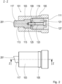
- Fixing means 101 shown has a base body 103 with an external thread 105.
- the external thread 105 serves to screw the fixing means 101 into a corresponding internal thread of a transmission housing.
- the internal thread of the gearbox housing is designed as a through thread so that the fixing means 101 can be inserted from the outside.
- a locknut 107 on the external thread 105 serves to secure the base body 103 against twisting.
- the base body 103 is provided with a through hole 109. If the base body 103 is screwed into the gearbox housing, a first mouth 111 of the through hole 109 is located outside the housing and a second mouth 113 inside.
- a first bolt 117 is arranged in a first area 115 of the through hole 109.
- the first bolt 117 is displaceable along a central axis of the through hole 109.
- a second area 119 of the through hole 109 has an internal thread.
- a second bolt 121 with a corresponding external thread is screwed into the internal thread.
- the first mouth 111 of the through hole 109 is also the mouth of the internal thread of the second region 119.
- the second bolt 121 is inserted through the first mouth 111 into the internal thread and screwed. As a result, it moves in the direction of the second mouth 113 and finally penetrates into the first area 115 of the through hole 109. Accordingly, the first bolt 117 is displaced by the second bolt 121 and pressed out of the second mouth 113 into the interior of the transmission. By clamping the first bolt 117 against a gear part by screwing in the second bolt 121, the gear part is fixed.
- the second bolt 121 has a longitudinal through hole 123. This is aligned with an internal thread 125 of the first bolt 117. This allows a bolt screw 127 to be passed through the through hole 123 of the second bolt 121 and screwed into the internal thread 125. With the screw 127, any jamming of the first bolt 117 can be removed and the first bolt 117 can be pulled back into its starting position.
- a screw 129 which is screwed into the base body 103 and engages in a groove 131 of the first bolt 117, prevents the first bolt 117 from rotating.
- a central axis of the first bolt 117 and the second bolt 121 and a central axis of the external thread 105 of the base body 103 run anti-parallel to one another.
- a variant with a parallel course of the central axes is in Fig. 2 shown.
- the first bolt 117 also has a beveled end face 201 here. On the one hand, this serves to better fix a gear part to be fixed, but on the other hand it also increases the risk of the first bolt 117 jamming.
Landscapes
- Engineering & Computer Science (AREA)
- General Engineering & Computer Science (AREA)
- Mechanical Engineering (AREA)
- Life Sciences & Earth Sciences (AREA)
- Sustainable Development (AREA)
- Sustainable Energy (AREA)
- Chemical & Material Sciences (AREA)
- Combustion & Propulsion (AREA)
- Connection Of Plates (AREA)
- General Details Of Gearings (AREA)
- Insertion Pins And Rivets (AREA)
Description
- Die Erfindung betrifft ein Fixiermittel nach dem Oberbegriff von Anspruch 1, ein Verfahren zum Fixieren eines Getriebeteils und ein Verfahren zum Lösen des Getriebeteils.
- Ein Fixiermittel für ein Getriebeteil ist aus
DE 10 2009 008607 A1 bekannt. - Zur Montage und Demontage großer Getriebe, etwa von Windkraftgetrieben, kann es erforderlich sein, einzelne Komponenten temporär zu fixieren. Dazu gibt es spezielle Fixiermittel. Diese werden durch das Getriebegehäuse eingeschraubt und halten die zu fixierende Komponente. Aufgrund der hohen Massen besteht die Gefahr, dass sich die Fixiermittel verformen. Ist die Verformung zu stark, verklemmen die Fixiermittel und lassen sich nicht mehr entfernen.
- Der Erfindung liegt die Aufgabe zugrunde, Getriebeteile zur Montage oder Demontage unter Umgehung der den aus dem Stand der Technik bekannten Lösungen innewohnenden Nachteile zu fixieren. Insbesondere sollen sich die Fixiermittel auch im Falle einer plastischen Verformung entfernen lassen.
- Diese Aufgabe wird gelöst durch ein Fixiermittel für ein Getriebeteil, beispielsweise einen Planetenträger, nach Anspruch 1 und ein Verfahren nach den unabhängigen Verfahrensansprüchen. Bevorzugte Weiterbildungen ergeben sich aus den Unteransprüchen und den in den Figuren dargestellten Ausführungsbeispielen.
- Ein bevorzugt einstückiges Stück des Fixiermittels - Grundkörper genannt - weist mindestens ein Außengewinde und mindestens ein Durchgangsloch auf. Das Außengewinde dient zum Einschrauben in ein Gewindeloch einer gehäusefesten Struktur, etwa in das Getriebegehäuse selbst.
- Ein Durchgangsloch ist ein Loch mit genau zwei Mündungen. Insbesondere kann es sich um eine Bohrung handeln. Eine Bohrung ist ein Durchgangsloch mit durchgängig kreisförmigem Querschnitt.
- Erfindungsgemäß weist das Fixiermittel einen ersten Bolzen und einen zweiten Bolzen auf. Der erste Bolzen lässt sich in einen ersten Bereich des ersten Durchgangslochs einstecken. Befindet sich der erste Bolzen in dem ersten Bereich des Durchgangslochs, ist er dort verschiebbar. Die Verschiebung erfolgt entlang einer Längsachse des Durchgangslochs. Handelt es sich bei dem Durchgangsloch um eine Bohrung, ist die Längsachse identisch mit einer Mittelachse der Bohrung, das heißt, einer Achse, um welche die Bohrung rotationssymmetrisch ist.
- Der zweite Bolzen weist ein Außengewinde auf. In einem zweiten Bereich des Durchgangslochs befindet sich ein zu dem Außengewinde des zweiten Bolzens korrespondierendes Innengewinde. Das Außengewinde des zweiten Bolzens ist mit dem Innengewinde des zweiten Bereichs des Durchgangslochs verschraubbar. Dies bedeutet, dass der zweite Bolzen in den zweiten Teil des Durchgangslochs einschraubbar ist.
- Der erste Bereich des Durchgangslochs und ein Bereich, den der zweite Bolzen beim Einschrauben in das Durchgangsloch überstreicht, überschneiden sich. Dies bedeutet, dass die Verschiebbarkeit des ersten Bolzens eingeschränkt wird, je weiter man den zweiten Bolzen in das Durchgangsloch einschraubt. Beim Einschrauben des zweiten Bolzens wird der erste Bolzen wenigstens teilweise von dem zweiten Bolzen verdrängt und aus dem Durchgangsloch herausgedrückt. Auf diese Weise kommt eine Fixierung des zu fixierenden Getriebeteils zustande.
- Der zweite Bolzen weist ein vorzugsweise als Bohrung ausgestaltetes Durchgangsloch auf. Ein Innengewinde des ersten Bolzens fluchtet mit dem Durchgangsloch. Dies bedeutet, dass das Durchgangsloch und das Innengewinde entlang gerader Linien ausgerichtet sind. Die Linien verlaufen parallel zu den Mittelachsen des Innengewindes und des Durchgangslochs. Jede Linie verläuft in mehreren Punkten jeweils durch eine Mantelfläche des Durchgangslochs und das Innengewinde.
- Handelt es sich bei dem Durchgangsloch um eine Bohrung, ist die Flucht mit dem Innengewinde gleichbedeutend damit, dass die folgenden drei Bedingungen erfüllt sind:
- 1. Das Durchgangsloch und das Innengewinde sind koaxial zueinander ausgerichtet;
- 2. ein Außendurchmesser des Innengewindes ist mindestens so groß wie ein Durchmesser des Durchgangslochs; und
- 3. das Durchgangsloch und das Innengewinde sind gegenüberliegend angeordnet.
- Bei einer koaxialen Ausrichtung des Durchgangslochs und des Innengewindes sind die Mittelachsen des Durchgangslochs und des Innengewindes identisch. Das Durchgangsloch und das Innengewinde sind gegenüberliegend ausgerichtet, wenn zwischen einer Mündung des Durchgangslochs und einer Mündung des Innengewindes ausschließlich ein Luftspalt verläuft, oder wenn die beiden Mündungen aufeinander aufliegen.
- Die erfindungsgemäße Anordnung ermöglicht es, eine Schraube, etwa eine Bolzenschraube, durch das Durchgangsloch hindurchzuführen und in das Innengewinde einzuschrauben. Der Bolzen bildet dann ein Widerlager für den Kopf der Schraube, wobei das Kinn des Kopfs auf dem Rand einer Mündung des Durchgangslochs aufliegt. Wird nun die Schraube in das Innengewinde eingeschraubt, verspannt sie sich zwischen dem ersten Bolzen und dem zweiten Bolzen bzw. zwischen dem Innengewinde und dem Rand der Mündung. Der erste Bolzen wird dadurch in das Durchgangsloch hineingezogen. Durch die Kraft, welche die Schraube infolge der Verspannung auf den ersten Bolzen aufbringt, lässt sich der erste Bolzen auch dann noch bewegen, wenn er sich durch plastische Verformung in dem ersten Teil des Durchgangslochs verklemmt hat.
- In einer bevorzugten Weiterbildung weist der erste Bolzen eine längs, das heißt entlang der identischen Mittelachsen des ersten Bolzens, des zweiten Bolzens, des Durchgangslochs des Grundkörpers, des Innengewindes des ersten Grundkörpers und des Durchgangslochs des zweiten Grundkörpers, verlaufende Nut auf. Eine Nut ist eine längliche Vertiefung einer Oberfläche. Sie zeichnet sich gegenüber anderen Vertiefungen der Oberfläche durch einen entlang des Verlaufs der Nut unveränderlichen Querschnitt aus. Der Querschnitt ist also gegenüber einer orthogonal zu einer den Verlauf der Nut beschreibenden Kurve ausgerichteten Schnittebene invariant. Vorliegend handelt es sich bei der genannten Kurve um eine Gerade, die parallel zu den genannten Mittelachsen verläuft.
- Weiterbildungsgemäß greift ein Teil des Grundkörpers in die Nut ein. Dadurch wird verhindert, dass sich der erste Bolzen dreht, wenn eine Schraube in sein Innengewinde eingeschraubt wird. Der längliche Verlauf der Nut erlaubt eine Verschiebung des ersten Bolzens in dem ersten Bereich des Durchgangslochs. Bevorzugt weist der Grundkörper eine Schraube auf, die den genannten Teil des Grundkörpers bildet, die also in die Nut eingreift.
- Alternativ kann der Grundkörper die Nut aufweisen, wobei ein Teil des ersten Bolzens in die Nut eingreift.
- Ein erfindungsgemäßes Verfahren dient dazu, unter Verwendung des erfindungsgemäßen Fixiermittels oder einer bevorzugten Weiterbildung ein Getriebeteil, etwa einen Planetenträger, zu fixieren. Das Verfahren wird in folgenden Schritten ausgeführt:
- Einsetzen des ersten Bolzens in den ersten Teil des Durchgangslochs des Grundkörpers;
- Einschrauben des Außengewindes des Grundkörpers in ein Innengewinde einer gehäusefesten Struktur des Getriebes, etwa in das Gehäuse selbst; und
- Verspannen des ersten Bolzens gegen den Getriebeteil durch Einschrauben des Außengewindes des zweiten Bolzens in das Innengewinde des Grundkörpers und Verspannen des zweiten Bolzens gegen den ersten Bolzen.
- Durch das Verspannen des zweiten Bolzens gegen den ersten Bolzen wird der erste Bolzen aus dem Durchgangsloch des Grundkörpers herausgedrückt und gegen den Getriebeteil verspannt. Kommt es dabei zu einer plastischen Verformung, sodass der erste Bolzen klemmt, lässt sich die Fixierung des Getriebeteils unter Anwendung eines weiteren erfindungsgemäßen Verfahrens lösen. Dieses Verfahren umfasst die folgenden Schritte:
- Positionieren des zweiten Bolzens derart, dass der erste Bolzen und der zweite Bolzen voneinander beabstandet sind;
- Durchführen einer Schraube durch das Durchgangsloch des zweiten Bolzens; und
- Einschrauben der Schraube in das Innengewinde des ersten Bolzens.
- Die Positionierung des zweiten Bolzens erfolgt, indem der zweite Bolzen mit seinem Außengewinde in dem Innengewinde des Grundkörpers verdreht wird. Dadurch lässt sich der Abstand des zweiten Bolzens von dem ersten Bolzen variieren. Die Schraube wird durch Einschrauben in das Innengewinde des ersten Bolzens, wie oben beschrieben, verspannt, sodass die Verklemmung des ersten Bolzens gelöst und der erste Bolzen zurück in das Durchgangsloch des Grundkörpers gezogen wird.
- Bevorzugte Ausführungsbeispiele der Erfindung sind in den Figuren dargestellt. Übereinstimmende Bezugsziffern kennzeichnen dabei gleiche oder funktionsgleiche Merkmale. Im Einzelnen zeigt:
- Fig. 1
- eine erste Variante eines Fixiermittels; und
- Fig. 2
- eine zweite Variante eines Fixiermittels.
- Das in
Fig. 1 dargestellte Fixiermittel 101 weist einen Grundkörper 103 mit einem Außengewinde 105 auf. Das Außengewinde 105 dient dazu, das Fixiermittel 101 in ein korrespondierendes Innengewinde eines Getriebegehäuses einzuschrauben. Das Innengewinde des Getriebegehäuses ist als Durchgangsgewinde ausgestaltet, sodass das Fixiermittel 101 von außen eingesetzt werden kann. Eine Gegenmutter 107 auf dem Außengewinde 105 dient dazu, den Grundkörper 103 gegen Verdrehen zu sichern. - Der Grundkörper 103 ist mit einem Durchgangsloch 109 versehen. Ist der Grundkörper 103 in das Getriebegehäuse eingeschraubt, befindet sich eine erste Mündung 111 des Durchgangslochs 109 außerhalb des Gehäuses und eine zweite Mündung 113 innerhalb.
- In einem ersten Bereich 115 des Durchgangslochs 109 ist ein erster Bolzen 117 angeordnet. Der erste Bolzen 117 ist entlang einer Mittelachse des Durchgangslochs 109 verschiebbar.
- Ein zweiter Bereich 119 des Durchgangslochs 109 weist ein Innengewinde auf. In das Innengewinde ist ein zweiter Bolzen 121 mit einem korrespondierenden Außengewinde eingeschraubt.
- Die erste Mündung 111 des Durchgangslochs 109 ist zugleich Mündung des Innengewindes des zweiten Bereichs 119. Durch die erste Mündung 111 hindurch wird der zweite Bolzen 121 in das Innengewinde eingeführt und verschraubt. Dadurch bewegt er sich in Richtung der zweiten Mündung 113 und dringt schließlich in den ersten Bereich 115 der Durchgangsbohrung 109 ein. Entsprechend wird der erste Bolzen 117 durch den zweiten Bolzen 121 verdrängt und aus der zweiten Mündung 113 heraus in das Getriebeinnere hineingedrückt. Indem der erste Bolzen 117 durch Einschrauben des zweiten Bolzens 121 gegen ein Getriebeteil verspannt wird, erfolgt eine Fixierung des Getriebeteils.
- Der zweite Bolzen 121 weist ein längs verlaufendes Durchgangsloch 123 auf. Dieses fluchtet mit einem Innengewinde 125 des ersten Bolzens 117. Dadurch lässt sich eine Bolzenschraube 127 durch das Durchgangsloch 123 des zweiten Bolzens 121 hindurchführen und in das Innengewinde 125 einschrauben. Mit der Schraube 127 lässt sich eine eventuelle Verklemmung des ersten Bolzens 117 aufheben und der erste Bolzen 117 in seine Ausgangsposition zurückziehen.
- Eine Schraube 129, die in dem Grundkörper 103 eingeschraubt ist und in eine Nut 131 des ersten Bolzens 117 eingreift, verhindert dabei, dass sich der erste Bolzen 117 dreht.
- Bei dem in
Fig. 1 dargestellten Fixiermittel 101 verlaufen eine Mittelachse des ersten Bolzens 117 und des zweiten Bolzens 121 und eine Mittelachse des Außengewindes 105 des Grundkörpers 103 antiparallel zueinander. Eine Variante mit parallelem Verlauf der Mittelachsen ist inFig. 2 dargestellt. Der erste Bolzen 117 weist hier zudem eine abgeschrägte Stirnfläche 201 auf. Dies dient einerseits der besseren Fixierung eines zu fixierenden Getriebeteils, vergrößert andererseits aber auch die Gefahr einer Verklemmung des ersten Bolzens 117. -
- 101
- Fixiermittel
- 103
- Grundkörper
- 105
- Außengewinde
- 107
- Gegenmutter
- 109
- Durchgangsloch
- 111
- erste Mündung
- 113
- zweite Mündung
- 115
- erster Bereich
- 117
- erster Bolzen
- 119
- zweiter Bereich
- 121
- zweiter Bolzen
- 123
- Durchgangsloch
- 125
- Innengewinde
- 127
- Bolzenschraube
- 129
- Schraube
- 131
- Nut
- 201
- Stirnfläche
Claims (4)
- Fixiermittel (101) für ein Getriebeteil, wobei das Fixiermittel einen Grundkörper (103) aufweist, wobei der Grundkörper (103) mindestens ein Außengewinde (105) und mindestens ein Durchgangsloch (109) aufweist; wobei das Fixiermitteleinen in einem ersten Bereich (115) des Durchgangslochs (109) verschiebbaren ersten Bolzen (117) und einen zweiten Bolzen (121) mit einem Außengewinde aufweist; wobeiein zweiter Bereich (119) des Durchgangslochs (109) mindestens ein mit dem Außengewinde des zweiten Bolzens (121) verschraubbares Innengewinde aufweist;und wobeider zweite Bolzen (121) ein Durchgangsloch und der erste Bolzen (117) ein mit dem Durchgangsloch fluchtendes Innengewinde (125) aufweisen.
- Fixiermittel (101) nach Anspruch 1; dadurch gekennzeichnet, dass der erste Bolzen (117) mindestens eine längs verlaufende Nut (131) aufweist; wobei ein Teil (129) des Grundkörpers (103) in die Nut (131) eingreift.
- Verfahren zum Fixieren eines Getriebeteils unter Verwendung eines Fixiermittels (101) nach einem der vorhergehenden Ansprüche; mit den Schritten:- Einsetzen des ersten Bolzens (117) in den ersten Bereich (115) des Durchgangslochs (109) des Grundkörpers (103);- Einschrauben des Außengewinde (105) des Grundkörpers (103) in ein Innengewinde einer gehäusefesten Struktur des Getriebes; und- Verspannen des ersten Bolzens (117) gegen den Getriebeteil durch Einschrauben des Außengewindes des zweiten Bolzens (121) in das Innengewinde des Grundkörpers (103) und Verspannen des zweiten Bolzens (121) gegen den ersten Bolzen (117).
- Verfahren zum Lösen einer gemäß dem vorhergehenden Anspruch hergestellten Fixierung; mit den Schritten- Positionieren des zweiten Bolzens (121) derart, dass der erste Bolzen (117) und der zweite Bolzen (121) voneinander beabstandet sind;- Durchführen einer Schraube (127) durch das Durchgangsloch des zweiten Bolzens (121), und- Einschrauben in das Innengewinde (125) des ersten Bolzens (117).
Applications Claiming Priority (2)
| Application Number | Priority Date | Filing Date | Title |
|---|---|---|---|
| DE102019214094.7A DE102019214094A1 (de) | 2019-09-17 | 2019-09-17 | Fixiermittel für schwere Getriebeteile |
| PCT/EP2020/073037 WO2021052698A1 (de) | 2019-09-17 | 2020-08-18 | Fixiermittel für schwere getriebeteile |
Publications (2)
| Publication Number | Publication Date |
|---|---|
| EP4031765A1 EP4031765A1 (de) | 2022-07-27 |
| EP4031765B1 true EP4031765B1 (de) | 2023-09-13 |
Family
ID=72340316
Family Applications (1)
| Application Number | Title | Priority Date | Filing Date |
|---|---|---|---|
| EP20765210.8A Active EP4031765B1 (de) | 2019-09-17 | 2020-08-18 | Fixiermittel für schwere getriebeteile |
Country Status (7)
| Country | Link |
|---|---|
| US (1) | US11635104B2 (de) |
| EP (1) | EP4031765B1 (de) |
| CN (1) | CN113994106B (de) |
| DE (1) | DE102019214094A1 (de) |
| ES (1) | ES2964887T3 (de) |
| FI (1) | FI4031765T3 (de) |
| WO (1) | WO2021052698A1 (de) |
Families Citing this family (2)
| Publication number | Priority date | Publication date | Assignee | Title |
|---|---|---|---|---|
| DE102021211984A1 (de) * | 2021-10-25 | 2023-04-27 | Aktiebolaget Skf | Rotorlagerungsanordnung für Strömungskraftanlage |
| EP4530495A1 (de) | 2023-09-27 | 2025-04-02 | Flender GmbH | Abstützelement für getriebekomponenten |
Family Cites Families (10)
| Publication number | Priority date | Publication date | Assignee | Title |
|---|---|---|---|---|
| DE3433738A1 (de) * | 1984-09-14 | 1986-03-20 | Fa. Carl Zeiss, 7920 Heidenheim | Einrichtung zur lagemaessigen fixierung eines gewindebolzens |
| US4602890A (en) * | 1985-02-22 | 1986-07-29 | Randall Equipment Company | Ratchet assembly and snap lock mechanism therefor |
| JP2921437B2 (ja) | 1995-04-12 | 1999-07-19 | トヨタ自動車株式会社 | 締結構造 |
| DE202005013328U1 (de) * | 2005-08-24 | 2006-02-02 | Weber, Thomas | Arretier- und entsperrbare Verdreheinheit für wälzgelagerte Planetenräder in Windkraft-Planetengetrieben mit kassettenartigem Aufbau von Planetenrad, Bolzen und Lagern |
| CN201301859Y (zh) | 2008-12-01 | 2009-09-02 | 北京谊安医疗系统股份有限公司 | 固定装置 |
| DE102009008607A1 (de) * | 2009-02-12 | 2010-08-19 | Nordex Energy Gmbh | Vorrichtung zur Arretierung eines Rotorblatts einer Windenergieanlage |
| DE102010040654A1 (de) * | 2010-09-13 | 2012-03-15 | Repower Systems Se | Demontage eines Getriebes einer Windenergieanlage |
| DE102014201465A1 (de) * | 2014-01-28 | 2015-07-30 | Zf Friedrichshafen Ag | Modulare Kopplung eines Windkraftgetriebes mit einem Generator |
| JP2017516632A (ja) * | 2014-06-06 | 2017-06-22 | イーライ リリー アンド カンパニー | 投与量フィードバック機構の回転可能な端部 |
| DE102017222766A1 (de) * | 2017-12-14 | 2019-06-19 | Kipp Verpachtungen E.K. | Unsymmetrischer Arretierbolzen mit unterschiedlichen Drehpositionen |
-
2019
- 2019-09-17 DE DE102019214094.7A patent/DE102019214094A1/de active Pending
-
2020
- 2020-08-18 WO PCT/EP2020/073037 patent/WO2021052698A1/de not_active Ceased
- 2020-08-18 US US17/642,958 patent/US11635104B2/en active Active
- 2020-08-18 FI FIEP20765210.8T patent/FI4031765T3/fi active
- 2020-08-18 CN CN202080044758.9A patent/CN113994106B/zh active Active
- 2020-08-18 ES ES20765210T patent/ES2964887T3/es active Active
- 2020-08-18 EP EP20765210.8A patent/EP4031765B1/de active Active
Also Published As
| Publication number | Publication date |
|---|---|
| ES2964887T3 (es) | 2024-04-10 |
| US20220333631A1 (en) | 2022-10-20 |
| DE102019214094A1 (de) | 2021-03-18 |
| EP4031765A1 (de) | 2022-07-27 |
| FI4031765T3 (fi) | 2023-12-13 |
| US11635104B2 (en) | 2023-04-25 |
| CN113994106A (zh) | 2022-01-28 |
| WO2021052698A1 (de) | 2021-03-25 |
| CN113994106B (zh) | 2023-07-18 |
Similar Documents
| Publication | Publication Date | Title |
|---|---|---|
| EP2325502B1 (de) | Anordnung und Verfahren zum Verbinden eines Zubehörteils mit einem Operationstisch | |
| EP3054171B1 (de) | Nietverbindungsanordnung sowie verfahren zu dessen herstellung | |
| DE102015109278B4 (de) | Verbindungssystem, Klemmschraube, Verfahren zum Verbinden zweier Bauteile | |
| EP3032093B1 (de) | Befestigungsvorrichtung zur befestigung eines rotorblattes an einer rotornabe einer windkraftanlage | |
| EP3565976B1 (de) | Vorrichtung zur drehmomentbegrenzung mit drei stegen | |
| DE102007019061B4 (de) | Kopflose Verschraubung | |
| EP4035834B1 (de) | Anordnung aus einer spannvorrichtung für eine schraubverbindung sowie einer sicherheitseinrichtung | |
| EP2224143B1 (de) | Mutter, Schraubverbindung, Profilverbindung sowie Verfahren zum Herstellen einer Mutter | |
| EP3132146A1 (de) | Befestigungsvorrichtung | |
| DE10049348A1 (de) | Linearführungsanordnung | |
| EP4031765A1 (de) | Fixiermittel für schwere getriebeteile | |
| EP3141638A1 (de) | Befestigungsvorrichtung für kämmelemente an einem rundkamm | |
| DE69004477T2 (de) | Rolle. | |
| EP4095398B1 (de) | Vorrichtung zum ausgleichen von toleranzen zwischen zwei miteinander zu verbindenden bauteilen | |
| DE102020112157A1 (de) | Formschlüssige Bauteilverbindung und Energieverzehrvorrichtung einer Schienenfahrzeugkupplung mit einer solchen Bauteilverbindung | |
| EP3275597B1 (de) | Werkzeug und verfahren zum ein- und ausziehen von bauteilen | |
| DE3220743C2 (de) | Einrichtung zum Verzurren von Containern | |
| DE102009009365A1 (de) | Verliersicherung zum Sichern eines Verbindungselementes | |
| DE102013110189A1 (de) | Einstellvorrichtung | |
| EP2102038B1 (de) | Gehäuseanordnung einer wischeranlage mit schraubverbindung | |
| EP1881211A2 (de) | Befestigungsvorrichtung aus Schraube und Hülse | |
| EP1979557B1 (de) | Vorrichtung zur kopplung zweier bauteile | |
| DE102018122701A1 (de) | Haltersystem zur Befestigung eines Behälters an einem Fahrzeug | |
| DE19527602A1 (de) | Vorrichtung zum Befestigen von Gegenständen | |
| DE102004034918B4 (de) | Verbindung zwischen zwei Gehäuseteilen |
Legal Events
| Date | Code | Title | Description |
|---|---|---|---|
| STAA | Information on the status of an ep patent application or granted ep patent |
Free format text: STATUS: UNKNOWN |
|
| STAA | Information on the status of an ep patent application or granted ep patent |
Free format text: STATUS: THE INTERNATIONAL PUBLICATION HAS BEEN MADE |
|
| PUAI | Public reference made under article 153(3) epc to a published international application that has entered the european phase |
Free format text: ORIGINAL CODE: 0009012 |
|
| STAA | Information on the status of an ep patent application or granted ep patent |
Free format text: STATUS: REQUEST FOR EXAMINATION WAS MADE |
|
| 17P | Request for examination filed |
Effective date: 20211026 |
|
| AK | Designated contracting states |
Kind code of ref document: A1 Designated state(s): AL AT BE BG CH CY CZ DE DK EE ES FI FR GB GR HR HU IE IS IT LI LT LU LV MC MK MT NL NO PL PT RO RS SE SI SK SM TR |
|
| DAV | Request for validation of the european patent (deleted) | ||
| DAX | Request for extension of the european patent (deleted) | ||
| GRAP | Despatch of communication of intention to grant a patent |
Free format text: ORIGINAL CODE: EPIDOSNIGR1 |
|
| STAA | Information on the status of an ep patent application or granted ep patent |
Free format text: STATUS: GRANT OF PATENT IS INTENDED |
|
| INTG | Intention to grant announced |
Effective date: 20230508 |
|
| GRAS | Grant fee paid |
Free format text: ORIGINAL CODE: EPIDOSNIGR3 |
|
| GRAA | (expected) grant |
Free format text: ORIGINAL CODE: 0009210 |
|
| STAA | Information on the status of an ep patent application or granted ep patent |
Free format text: STATUS: THE PATENT HAS BEEN GRANTED |
|
| AK | Designated contracting states |
Kind code of ref document: B1 Designated state(s): AL AT BE BG CH CY CZ DE DK EE ES FI FR GB GR HR HU IE IS IT LI LT LU LV MC MK MT NL NO PL PT RO RS SE SI SK SM TR |
|
| REG | Reference to a national code |
Ref country code: CH Ref legal event code: EP |
|
| REG | Reference to a national code |
Ref country code: DE Ref legal event code: R096 Ref document number: 502020005254 Country of ref document: DE |
|
| REG | Reference to a national code |
Ref country code: IE Ref legal event code: FG4D Free format text: LANGUAGE OF EP DOCUMENT: GERMAN |
|
| REG | Reference to a national code |
Ref country code: FI Ref legal event code: FGE |
|
| REG | Reference to a national code |
Ref country code: LT Ref legal event code: MG9D |
|
| REG | Reference to a national code |
Ref country code: NL Ref legal event code: MP Effective date: 20230913 |
|
| PG25 | Lapsed in a contracting state [announced via postgrant information from national office to epo] |
Ref country code: GR Free format text: LAPSE BECAUSE OF FAILURE TO SUBMIT A TRANSLATION OF THE DESCRIPTION OR TO PAY THE FEE WITHIN THE PRESCRIBED TIME-LIMIT Effective date: 20231214 |
|
| PG25 | Lapsed in a contracting state [announced via postgrant information from national office to epo] |
Ref country code: SE Free format text: LAPSE BECAUSE OF FAILURE TO SUBMIT A TRANSLATION OF THE DESCRIPTION OR TO PAY THE FEE WITHIN THE PRESCRIBED TIME-LIMIT Effective date: 20230913 Ref country code: RS Free format text: LAPSE BECAUSE OF FAILURE TO SUBMIT A TRANSLATION OF THE DESCRIPTION OR TO PAY THE FEE WITHIN THE PRESCRIBED TIME-LIMIT Effective date: 20230913 Ref country code: NO Free format text: LAPSE BECAUSE OF FAILURE TO SUBMIT A TRANSLATION OF THE DESCRIPTION OR TO PAY THE FEE WITHIN THE PRESCRIBED TIME-LIMIT Effective date: 20231213 Ref country code: LV Free format text: LAPSE BECAUSE OF FAILURE TO SUBMIT A TRANSLATION OF THE DESCRIPTION OR TO PAY THE FEE WITHIN THE PRESCRIBED TIME-LIMIT Effective date: 20230913 Ref country code: LT Free format text: LAPSE BECAUSE OF FAILURE TO SUBMIT A TRANSLATION OF THE DESCRIPTION OR TO PAY THE FEE WITHIN THE PRESCRIBED TIME-LIMIT Effective date: 20230913 Ref country code: HR Free format text: LAPSE BECAUSE OF FAILURE TO SUBMIT A TRANSLATION OF THE DESCRIPTION OR TO PAY THE FEE WITHIN THE PRESCRIBED TIME-LIMIT Effective date: 20230913 Ref country code: GR Free format text: LAPSE BECAUSE OF FAILURE TO SUBMIT A TRANSLATION OF THE DESCRIPTION OR TO PAY THE FEE WITHIN THE PRESCRIBED TIME-LIMIT Effective date: 20231214 |
|
| PG25 | Lapsed in a contracting state [announced via postgrant information from national office to epo] |
Ref country code: NL Free format text: LAPSE BECAUSE OF FAILURE TO SUBMIT A TRANSLATION OF THE DESCRIPTION OR TO PAY THE FEE WITHIN THE PRESCRIBED TIME-LIMIT Effective date: 20230913 |
|
| PG25 | Lapsed in a contracting state [announced via postgrant information from national office to epo] |
Ref country code: IS Free format text: LAPSE BECAUSE OF FAILURE TO SUBMIT A TRANSLATION OF THE DESCRIPTION OR TO PAY THE FEE WITHIN THE PRESCRIBED TIME-LIMIT Effective date: 20240113 |
|
| REG | Reference to a national code |
Ref country code: ES Ref legal event code: FG2A Ref document number: 2964887 Country of ref document: ES Kind code of ref document: T3 Effective date: 20240410 |
|
| PG25 | Lapsed in a contracting state [announced via postgrant information from national office to epo] |
Ref country code: SM Free format text: LAPSE BECAUSE OF FAILURE TO SUBMIT A TRANSLATION OF THE DESCRIPTION OR TO PAY THE FEE WITHIN THE PRESCRIBED TIME-LIMIT Effective date: 20230913 Ref country code: RO Free format text: LAPSE BECAUSE OF FAILURE TO SUBMIT A TRANSLATION OF THE DESCRIPTION OR TO PAY THE FEE WITHIN THE PRESCRIBED TIME-LIMIT Effective date: 20230913 Ref country code: IS Free format text: LAPSE BECAUSE OF FAILURE TO SUBMIT A TRANSLATION OF THE DESCRIPTION OR TO PAY THE FEE WITHIN THE PRESCRIBED TIME-LIMIT Effective date: 20240113 Ref country code: EE Free format text: LAPSE BECAUSE OF FAILURE TO SUBMIT A TRANSLATION OF THE DESCRIPTION OR TO PAY THE FEE WITHIN THE PRESCRIBED TIME-LIMIT Effective date: 20230913 Ref country code: CZ Free format text: LAPSE BECAUSE OF FAILURE TO SUBMIT A TRANSLATION OF THE DESCRIPTION OR TO PAY THE FEE WITHIN THE PRESCRIBED TIME-LIMIT Effective date: 20230913 Ref country code: PT Free format text: LAPSE BECAUSE OF FAILURE TO SUBMIT A TRANSLATION OF THE DESCRIPTION OR TO PAY THE FEE WITHIN THE PRESCRIBED TIME-LIMIT Effective date: 20240115 Ref country code: SK Free format text: LAPSE BECAUSE OF FAILURE TO SUBMIT A TRANSLATION OF THE DESCRIPTION OR TO PAY THE FEE WITHIN THE PRESCRIBED TIME-LIMIT Effective date: 20230913 |
|
| PG25 | Lapsed in a contracting state [announced via postgrant information from national office to epo] |
Ref country code: PL Free format text: LAPSE BECAUSE OF FAILURE TO SUBMIT A TRANSLATION OF THE DESCRIPTION OR TO PAY THE FEE WITHIN THE PRESCRIBED TIME-LIMIT Effective date: 20230913 Ref country code: IT Free format text: LAPSE BECAUSE OF FAILURE TO SUBMIT A TRANSLATION OF THE DESCRIPTION OR TO PAY THE FEE WITHIN THE PRESCRIBED TIME-LIMIT Effective date: 20230913 |
|
| REG | Reference to a national code |
Ref country code: DE Ref legal event code: R097 Ref document number: 502020005254 Country of ref document: DE |
|
| PG25 | Lapsed in a contracting state [announced via postgrant information from national office to epo] |
Ref country code: DK Free format text: LAPSE BECAUSE OF FAILURE TO SUBMIT A TRANSLATION OF THE DESCRIPTION OR TO PAY THE FEE WITHIN THE PRESCRIBED TIME-LIMIT Effective date: 20230913 |
|
| PLBE | No opposition filed within time limit |
Free format text: ORIGINAL CODE: 0009261 |
|
| STAA | Information on the status of an ep patent application or granted ep patent |
Free format text: STATUS: NO OPPOSITION FILED WITHIN TIME LIMIT |
|
| PG25 | Lapsed in a contracting state [announced via postgrant information from national office to epo] |
Ref country code: DK Free format text: LAPSE BECAUSE OF FAILURE TO SUBMIT A TRANSLATION OF THE DESCRIPTION OR TO PAY THE FEE WITHIN THE PRESCRIBED TIME-LIMIT Effective date: 20230913 |
|
| 26N | No opposition filed |
Effective date: 20240614 |
|
| PGFP | Annual fee paid to national office [announced via postgrant information from national office to epo] |
Ref country code: FI Payment date: 20240821 Year of fee payment: 5 |
|
| PG25 | Lapsed in a contracting state [announced via postgrant information from national office to epo] |
Ref country code: SI Free format text: LAPSE BECAUSE OF FAILURE TO SUBMIT A TRANSLATION OF THE DESCRIPTION OR TO PAY THE FEE WITHIN THE PRESCRIBED TIME-LIMIT Effective date: 20230913 |
|
| PG25 | Lapsed in a contracting state [announced via postgrant information from national office to epo] |
Ref country code: SI Free format text: LAPSE BECAUSE OF FAILURE TO SUBMIT A TRANSLATION OF THE DESCRIPTION OR TO PAY THE FEE WITHIN THE PRESCRIBED TIME-LIMIT Effective date: 20230913 |
|
| PG25 | Lapsed in a contracting state [announced via postgrant information from national office to epo] |
Ref country code: BG Free format text: LAPSE BECAUSE OF FAILURE TO SUBMIT A TRANSLATION OF THE DESCRIPTION OR TO PAY THE FEE WITHIN THE PRESCRIBED TIME-LIMIT Effective date: 20230913 |
|
| PG25 | Lapsed in a contracting state [announced via postgrant information from national office to epo] |
Ref country code: BG Free format text: LAPSE BECAUSE OF FAILURE TO SUBMIT A TRANSLATION OF THE DESCRIPTION OR TO PAY THE FEE WITHIN THE PRESCRIBED TIME-LIMIT Effective date: 20230913 |
|
| REG | Reference to a national code |
Ref country code: CH Ref legal event code: PL |
|
| PG25 | Lapsed in a contracting state [announced via postgrant information from national office to epo] |
Ref country code: LU Free format text: LAPSE BECAUSE OF NON-PAYMENT OF DUE FEES Effective date: 20240818 |
|
| GBPC | Gb: european patent ceased through non-payment of renewal fee |
Effective date: 20240818 |
|
| PG25 | Lapsed in a contracting state [announced via postgrant information from national office to epo] |
Ref country code: MC Free format text: LAPSE BECAUSE OF FAILURE TO SUBMIT A TRANSLATION OF THE DESCRIPTION OR TO PAY THE FEE WITHIN THE PRESCRIBED TIME-LIMIT Effective date: 20230913 Ref country code: CH Free format text: LAPSE BECAUSE OF NON-PAYMENT OF DUE FEES Effective date: 20240831 |
|
| REG | Reference to a national code |
Ref country code: BE Ref legal event code: MM Effective date: 20240831 |
|
| PG25 | Lapsed in a contracting state [announced via postgrant information from national office to epo] |
Ref country code: GB Free format text: LAPSE BECAUSE OF NON-PAYMENT OF DUE FEES Effective date: 20240818 |
|
| PG25 | Lapsed in a contracting state [announced via postgrant information from national office to epo] |
Ref country code: BE Free format text: LAPSE BECAUSE OF NON-PAYMENT OF DUE FEES Effective date: 20240831 |
|
| PG25 | Lapsed in a contracting state [announced via postgrant information from national office to epo] |
Ref country code: FR Free format text: LAPSE BECAUSE OF NON-PAYMENT OF DUE FEES Effective date: 20240831 |
|
| PG25 | Lapsed in a contracting state [announced via postgrant information from national office to epo] |
Ref country code: IE Free format text: LAPSE BECAUSE OF NON-PAYMENT OF DUE FEES Effective date: 20240818 |
|
| PGFP | Annual fee paid to national office [announced via postgrant information from national office to epo] |
Ref country code: ES Payment date: 20250905 Year of fee payment: 6 |
|
| PGFP | Annual fee paid to national office [announced via postgrant information from national office to epo] |
Ref country code: DE Payment date: 20250624 Year of fee payment: 6 |
|
| PGFP | Annual fee paid to national office [announced via postgrant information from national office to epo] |
Ref country code: AT Payment date: 20251020 Year of fee payment: 5 |
|
| PG25 | Lapsed in a contracting state [announced via postgrant information from national office to epo] |
Ref country code: CY Free format text: LAPSE BECAUSE OF FAILURE TO SUBMIT A TRANSLATION OF THE DESCRIPTION OR TO PAY THE FEE WITHIN THE PRESCRIBED TIME-LIMIT; INVALID AB INITIO Effective date: 20200818 |
|
| PG25 | Lapsed in a contracting state [announced via postgrant information from national office to epo] |
Ref country code: HU Free format text: LAPSE BECAUSE OF FAILURE TO SUBMIT A TRANSLATION OF THE DESCRIPTION OR TO PAY THE FEE WITHIN THE PRESCRIBED TIME-LIMIT; INVALID AB INITIO Effective date: 20200818 |
|
| PG25 | Lapsed in a contracting state [announced via postgrant information from national office to epo] |
Ref country code: FI Free format text: LAPSE BECAUSE OF NON-PAYMENT OF DUE FEES Effective date: 20250818 |