EP4031767B1 - Pumpensystem mit übertemperaturschutz - Google Patents
Pumpensystem mit übertemperaturschutz Download PDFInfo
- Publication number
- EP4031767B1 EP4031767B1 EP20785639.4A EP20785639A EP4031767B1 EP 4031767 B1 EP4031767 B1 EP 4031767B1 EP 20785639 A EP20785639 A EP 20785639A EP 4031767 B1 EP4031767 B1 EP 4031767B1
- Authority
- EP
- European Patent Office
- Prior art keywords
- fluid
- pump
- control
- thermally
- pressure
- Prior art date
- Legal status (The legal status is an assumption and is not a legal conclusion. Google has not performed a legal analysis and makes no representation as to the accuracy of the status listed.)
- Active
Links
Images






Classifications
-
- F—MECHANICAL ENGINEERING; LIGHTING; HEATING; WEAPONS; BLASTING
- F04—POSITIVE - DISPLACEMENT MACHINES FOR LIQUIDS; PUMPS FOR LIQUIDS OR ELASTIC FLUIDS
- F04B—POSITIVE-DISPLACEMENT MACHINES FOR LIQUIDS; PUMPS
- F04B1/00—Multi-cylinder machines or pumps characterised by number or arrangement of cylinders
- F04B1/12—Multi-cylinder machines or pumps characterised by number or arrangement of cylinders having cylinder axes coaxial with, or parallel or inclined to, main shaft axis
- F04B1/20—Multi-cylinder machines or pumps characterised by number or arrangement of cylinders having cylinder axes coaxial with, or parallel or inclined to, main shaft axis having rotary cylinder block
-
- F—MECHANICAL ENGINEERING; LIGHTING; HEATING; WEAPONS; BLASTING
- F04—POSITIVE - DISPLACEMENT MACHINES FOR LIQUIDS; PUMPS FOR LIQUIDS OR ELASTIC FLUIDS
- F04B—POSITIVE-DISPLACEMENT MACHINES FOR LIQUIDS; PUMPS
- F04B1/00—Multi-cylinder machines or pumps characterised by number or arrangement of cylinders
- F04B1/12—Multi-cylinder machines or pumps characterised by number or arrangement of cylinders having cylinder axes coaxial with, or parallel or inclined to, main shaft axis
- F04B1/26—Control
- F04B1/28—Control of machines or pumps with stationary cylinders
- F04B1/29—Control of machines or pumps with stationary cylinders by varying the relative positions of a swash plate and a cylinder block
-
- F—MECHANICAL ENGINEERING; LIGHTING; HEATING; WEAPONS; BLASTING
- F04—POSITIVE - DISPLACEMENT MACHINES FOR LIQUIDS; PUMPS FOR LIQUIDS OR ELASTIC FLUIDS
- F04B—POSITIVE-DISPLACEMENT MACHINES FOR LIQUIDS; PUMPS
- F04B1/00—Multi-cylinder machines or pumps characterised by number or arrangement of cylinders
- F04B1/12—Multi-cylinder machines or pumps characterised by number or arrangement of cylinders having cylinder axes coaxial with, or parallel or inclined to, main shaft axis
- F04B1/26—Control
-
- F—MECHANICAL ENGINEERING; LIGHTING; HEATING; WEAPONS; BLASTING
- F04—POSITIVE - DISPLACEMENT MACHINES FOR LIQUIDS; PUMPS FOR LIQUIDS OR ELASTIC FLUIDS
- F04B—POSITIVE-DISPLACEMENT MACHINES FOR LIQUIDS; PUMPS
- F04B49/00—Control, e.g. of pump delivery, or pump pressure of, or safety measures for, machines, pumps, or pumping installations, not otherwise provided for, or of interest apart from, groups F04B1/00 - F04B47/00
- F04B49/10—Other safety measures
-
- F—MECHANICAL ENGINEERING; LIGHTING; HEATING; WEAPONS; BLASTING
- F16—ENGINEERING ELEMENTS AND UNITS; GENERAL MEASURES FOR PRODUCING AND MAINTAINING EFFECTIVE FUNCTIONING OF MACHINES OR INSTALLATIONS; THERMAL INSULATION IN GENERAL
- F16K—VALVES; TAPS; COCKS; ACTUATING-FLOATS; DEVICES FOR VENTING OR AERATING
- F16K31/00—Actuating devices; Operating means; Releasing devices
- F16K31/002—Actuating devices; Operating means; Releasing devices actuated by temperature variation
Definitions
- the present disclosure relates generally to pump systems, and more particularly to pump systems with prevention mechanisms to prevent overheating of the working fluid.
- Some conventional pumps may use redundant temperature sensors that sense hydraulic system fluid temperatures for overheat prevention. If the temperature limits of the hydraulic fluid are exceeded, an electrical solenoid on the pump is actuated to reduce the output pressure of the pump so that the pump does not produce enough leakage and/or enough friction to lead to excessive fluid temperatures.
- One problem with this conventional method includes the need for redundant temperature sensors, the possibility of multiple temperature sensors being simultaneously incorrect, and the need for additional software. Such conventional methods, therefore, may be complex, and also may be too slow to react to rapidly rising temperatures of the fluid exiting the pump.
- Other conventional pump designs may utilize mechanical methods to reduce pump output pressure; however, these mechanisms generally are not detectable before every usage cycle (e.g., flight) for detecting latent failures, and also may be too slow to react to rapidly rising fluid temperatures.
- One aspect of the present disclosure provides a pump system having one or more prevention mechanisms that prevent excessive fluid temperature buildup of the fluid flowing through the system, such as those that can result from pump failure.
- the one or more of the prevention mechanisms may have no latent failures with a dormancy period greater than one usage cycle.
- one usage cycle may constitute a single flight.
- Such prevention mechanism(s) may enable detection before every usage cycle (e.g., flight) to better ensure that the system has no latent failure with a dormancy greater than one usage cycle (e.g., flight).
- the present disclosure provides a pump system having a prevention mechanism that includes a thermally-responsive material which senses an over-temperature event of the fluid in the system, and which cooperates with a fluid-operated control to decrease pump output pressure in response to the temperature of the thermally-responsive material being heated by the fluid up to or beyond an activation temperature of the material.
- the pump system may be configured to remain operational after the thermally-responsive material has reached or exceeded the activation temperature, such as by retaining the fluid within the pump system and/or maintaining operation of the pump at a decreased pump output pressure.
- a pump system includes: a pump for pumping fluid; a fluid-operated control fluidly connected to the pump and configured to increase or decrease pump displacement in response to a fluid pressure of the system being communicated to the fluid-operated control; and a thermally-responsive control component made with a thermally-responsive material, the thermally-responsive control component being located in the pump system such that the thermally-responsive material is in thermal communication with the fluid flowing through the pump system for effecting a change in temperature of the thermally-responsive material; wherein the thermally-responsive material is configured to have an activation temperature that is a predefined amount less than a maximum operating temperature of the fluid flowing through the pump system; and wherein the thermally-responsive control component is configured to cooperate with the fluid-operated control to cause a decrease in pump output pressure in response to the thermally-responsive material being heated by the fluid to a temperature that is equal to or greater than the activation temperature of the thermally-responsive material, and wherein the pump system can remain operational after the thermally-responsive material has reached or exceeded
- a pressure compensation valve assembly for a pump system includes: a valve body having an inlet for fluid communication with a discharge port of a pump of the system for communicating a discharge pressure of the pump to the pressure compensation valve assembly, and an outlet for fluid communication with a control actuator of the system for communicating a control pressure to the control actuator; a compensator spool movable in the valve body between the inlet and the outlet; a compensator spring configured to apply a biasing force against one side of the compensator spool which counteracts the discharge pressure exerted against an opposite side of the compensator spool, and wherein the compensator spool moves between the inlet and the outlet in response to opposing forces exerted on the compensator spool by the biasing spring on the one side and the discharge pressure on the opposite side to thereby control fluid exiting the outlet at the control pressure for being received by the control actuator which is operative to increase or decrease pump displacement in response to the control pressure; and a thermally-responsive control component made with a thermally-responsive material having
- a method of decreasing pump output pressure when a fluid of the pump is overheated includes: (i) pumping the fluid with the pump and discharging pressurized discharge fluid from the pump; (ii) routing at least some of the pressurized discharge fluid to a fluid-operated control; (iii) sensing a pressure of the pressurized discharge fluid with the fluid-operated control and outputting fluid at a charge pressure from the fluid-operated control; (iv) varying pump displacement in response to the charge pressure; (v) before, during, and/or after one or more of steps (i)-(iv), sensing fluid temperature with a thermally-responsive material having an activation temperature; (vi) when the temperature of the thermally-responsive material reaches the activation temperature, trigger the fluid-operated control to cause a decrease in pump output pressure; and (vii) wherein after activation of the thermally-responsive material, the fluid is maintained within a pump circuit containing the pump.
- a hydraulic system 10 for an aircraft which includes at least one exemplary pump system 12 having an exemplary pump 14 and pump control 16, as described in further detail below.
- the at least one pump system 12 forms a portion of a hydraulic circuit and includes inlet fluid conduits 17 for connection to a reservoir 18 of the hydraulic circuit for storing hydraulic fluid, and outlet fluid conduits 19 for connection to fluid-operated consumers 20 (e.g., motors, actuators, etc.) for controlling the aircraft.
- the pump system 12, or pump circuit also includes case drain fluid conduit(s) 21 which route output fluid from the pump 14 through a heat exchanger 22, which may be the fuel tank of the aircraft.
- the pump system 12 may include one or more additional pumps 24, such as supplemental pumps, which may supplement hydraulic power to the consumers 20 and serve for redundancy in the case of pump failure.
- the hydraulic system 10 is for a large commercial jet and includes three hydraulic sub-systems, or circuits, 11a, 11b and 11c; however, the aspects according to the present disclosure are not limited to such as system.
- the left 11a, center 11b, and right 11c systems may deliver hydraulic fluid at a rated pressure of 3,000 psi, for example, to operate flight controls, flap systems, actuators, landing gear, and brakes.
- Primary hydraulic power for the left 11a and right 11c systems is provided by two of the exemplary pumps 14, which are engine driven pumps in the illustrated embodiment.
- the primary pump 14 in each of the left 11a and right 11c systems is supplemented by an on-demand AC motor pump as the additional pump 24.
- primary hydraulic power for the center system 11b is provided by two electric motor pumps 25 (AC motor pumps) and supplemented by two air turbine-driven pumps 26.
- the center system 11b provides hydraulic power for the engine thrust reversers, primary flight controls, landing gear, andflaps/slats, for example.
- the left 11a and right 11c hydraulic systems are functionally the same.
- the left hydraulic system 11a supplies pressurized hydraulic fluid to operate the left thrust reverser and the flight control systems.
- the right hydraulic system 11c supplies pressurized hydraulic fluid to operate the right thrust reverser, flight control systems, and the normal brake system.
- the left hydraulic system 11a will be described in further detail below
- the reservoir 18 of the hydraulic subsystem 11a contains the hydraulic fluid supply for the pump system 12 having the main hydraulic pump 14 and the supplemental hydraulic pump 24.
- the reservoir 18 may be pressurized by bleed air through a reservoir pressurization module.
- the main pump 14 may draw fluid through the inlet fluid conduit 17, such as a standpipe, and the supplemental pump 24 may draw fluid from the bottom of the reservoir 18.
- the engine driven main pump 14 is the primary pump for the left hydraulic system 11a and operates whenever the engine operates.
- a suitable pump control mechanism 16 controls pump output pressure of the main pump 14.
- the supplemental pump 24 is the on-demand pump for the left hydraulic system 11a, which normally operates only when there is high hydraulic system demand.
- the hydraulic system 10 may include suitable temperature, pressure and quantity sensors, with suitable communications modules, for measuring temperature, pressure and quantity of the hydraulic fluid and communicating the measurements to the flight deck.
- a reservoir quantity transmitter (not shown) and temperature transducer (not shown) are installed on each of the reservoirs, and a hydraulic reservoir pressure switch is located on the pneumatic line between the reservoir pressurization module and the reservoir.
- the main pump 14 and supplemental pump 24 each may have a pressure transducer to measure pump output pressure, such as within filter modules of each of the pumps.
- a temperature transducer also may be installed in the case drain line of each filter module to measure pump case drain fluid temperature.
- a pressure relief valve also may be included on the filter module of the main pump 14 to protect the system against over-pressurization.
- a failure of the main pump 14 can cause a significant amount of heat generation that can be transferred to the hydraulic fluid.
- Such internal failure of the pump 14 may include faulty pump component(s) that generate excessive friction and heat, for example.
- internal, recirculating leakage from high pressure to low pressure may increase fluid temperature. If the temperature of the hydraulic fluid were to increase beyond a threshold level (e.g., 400°F; 205°C), then the heat transferred from the hydraulic fluid into the fuel could lead to a high-temperature reaction of the fuel.
- the exemplary pump system described herein can mitigate such overheating of the system fluid by providing a unique overheat prevention mechanism that senses temperature of the hydraulic fluid, and which cooperates with a pump control in response to such sensing to prevent excessive heat buildup of the hydraulic fluid.
- the prevention mechanism has no latent failures with a dormancy period greater than one usage cycle.
- a latent failure is one whose presence is not apparent to the flight crew or maintenance personnel.
- one usage cycle may constitute a single flight.
- such a prevention mechanism may enable detection before every usage cycle (e.g., flight) to better ensure the system has no dormant failure with a latency greater than one usage (e.g., flight) cycle. This makes the pump system and/or prevention mechanism intrinsically incapable of producing fluid temperatures that exceed a certain threshold value, and enables flight crew and/or maintenance personnel to detect any failures of the prevention mechanism during each usage cycle (flight).
- the overheat prevention mechanism of the exemplary pump system 12 includes a thermally-responsive control component 30 made with a thermally-responsive material.
- the thermally-responsive control component 30 is located in the pump system 12 such that the thermally-responsive material is in thermal communication with the fluid flowing through the system for effecting a change in temperature of the thermally-responsive material.
- the thermally-responsive material is configured to have an activation temperature that is a predefined amount less than a maximum operating temperature of the fluid flowing through the system.
- the thermally-responsive control component 30 is configured to cooperate with the pump control mechanism 16 in the system to cause a decrease pump displacement in response to the thermally-responsive material being heated by the fluid to a temperature that is equal to or greater than the activation temperature of the thermally-responsive material.
- the exemplary pump 14 may be any suitable pump, including a variable displacement pump, such as a swashplate-type axial piston pump, a radial piston pump, an axial piston bent-axis type pump, a variable vane pump, or the like.
- the pump 14 includes a variable displacement axial piston pump that is driven by a prime mover, such as the aircraft engine described above.
- the exemplary control mechanism 16 may include any suitable control for controlling output pressure of the pump.
- the control mechanism 16 is a fluid-operated control (also 16) having one or more parts fluidly connected to and/or mechanically coupled to the pump 14 and which is configured to increase or decrease pump displacement in response to a fluid pressure of the system being communicated to the fluid-operated control 16.
- the exemplary fluid-operated control 16 also cooperates with the thermally-responsive control component 30 to decrease pump output pressure in response to the thermally-responsive material being heated to or above its activation temperature, as described in further detail below.
- the fluid-operated control 16 includes a pressure compensation valve and/or a control piston for controlling an angle of a swashplate of the pump, as described in further detail below.
- Such fluid-operated control may provide a relatively simple, reliable, and fast method of controlling the pump while enabling detection of latent failure modes.
- the thermally-responsive control component 30 may be made with any suitable thermally-responsive material having an activation temperature that causes a transformation, transition or stimulus of the material in such a way that it enables the thermally-responsive control component 30 to operatively signal to the control mechanism 16 that pump output pressure should be reduced.
- the thermally-responsive material is configured to have an activation temperature that is a predefined amount less than a maximum operating temperature of the fluid flowing through the system to prevent failures within the system, such as to prevent high-temperature reactions of the liquid fuel in the aircraft, for example.
- the activation temperature may be a value in a range from about 10°C to about 100°C less than the maximum operating temperature of the fluid in the system 12.
- the thermally-responsive material may have an activation temperature with a value in a range from about 221 °F (about 105°C) to about 383°F (about 195°C), such as, an activation temperature of about 105°C, about 125°C, about 150°C, about 175°C, about 190°C, or about 195°C (including all values between the stated values).
- the thermally-responsive material may include a phase transition material that is configured to transition from one phase to another phase at the activation temperature.
- the phase transition material may be configured as a thermal actuator, a thermal switch, or a thermal fuse, for example.
- the phase transition material may be configured to undergo a first order phase transition at the activation temperature, such as a transition from solid to liquid, for example, in which the activation temperature is the melting point of the material.
- the phase transition material is a eutectic alloy that transitions directly from solid to liquid at a prescribed temperature.
- Non-limiting examples of such eutectic alloys that may be used in the system 12 include Indalloy 86 (60% bismuth, 40% cadmium) with a eutectic melting point of 144°C; or Indalloy 103 (67.8% tin, 32.2% cadmium) with a eutectic melting point of 177°C.
- the phase transition material may be configured to undergo a transition in its atomic structure, such as its crystal structure.
- the phase transition material may be a shape memory material, such as a shape memory alloy or a shape memory polymer.
- a shape memory alloy may be configured to transition between an austenitic crystal state to a martensitic crystal state at an activation temperature.
- a shape memory polymer may be configured to transition between a deformed state (temporary shape) to an original (permanent) shape induced by going above or below the activation temperature.
- the phase transition material may include a thermal expansion material that is configured to expand by a prescribed amount in a particular direction at a prescribed activation temperature, as described in further detail below.
- the thermally-responsive control component 30 may be positioned at any suitable location within the pump system 12 for providing suitable thermal communication with the hydraulic fluid to sense hydraulic fluid temperature via the thermally-responsive material.
- the thermal communication may include direct contact with the hydraulic fluid or indirect contact with the hydraulic fluid.
- the thermally-responsive material may be a material that is compatible with the hydraulic fluid at the operating temperatures, or which may have a coating that is compatible with the fluid.
- the thermally-responsive control component 30 made with the thermally-responsive material may have any suitable shape or form for cooperating with other components of the pump system to effect signaling to the control mechanism 16 to reduce pump output pressure when the activation temperature of the thermally-responsive material is reached or exceeded.
- the thermally-responsive control component 30 may be formed as a spacer, a plug, a switch, an actuator, a spring, an expander, a support, or any other suitable structure.
- the thermally-responsive control component 30 may include a portion that is made with the thermally-responsive material, or may be made entirely of the thermally-responsive material.
- the thermally-responsive control component also may be made with other materials in addition to the thermally-responsive material as may be desirable for particular applications.
- the thermally-responsive control component 30 relies on the physical properties of the thermally-responsive material, which can be assumed to have no mechanical failure modes.
- the irreversible phase transition (e.g., melting) of the material impacts the fundamental operation of the pump system such that triggering of the phase transition (e.g., eutectic melt) can be detected during the usage cycle in which the failure occurred (e.g., flight). This ensures the prevention mechanism will have no latent failures with a dormancy period greater than one usage cycle.
- the efficacy of the prevention mechanism also may depend on the cooperative relationship between the thermally-responsive control component 30 and the fluid-operated control 16.
- the thermally-responsive control component 30 may enable a relatively quick response to overheating events by disabling or reducing the power input at the source of the heat generation (e.g., faulty pump).
- the pump system 12 also is configured to remain operational even after the thermally-responsive material has reached or exceeded its activation temperature and completed its transformation or transition.
- the activation of the thermally-responsive material(e.g., eutectic) may be such that the hydraulic fluid remains in the pump system to enable continued operation of additional pump(s), such as supplemental pump 24.
- the thermally-responsive material e.g., via melting
- the hydraulic fluid may return to the pump case or other portion of the pump circuit 12. This is in contrast with conventional pump case fuse plug designs in which the hydraulic fluid is traditionally discharged out of the system and dumped overboard.
- the activation of the thermally-responsive material may enable the pump 14 to remain operation with a decreased pump output pressure, such that the pump does not generate excessive heat due to any internal failure.
- a pump system 112 including a pump 114, a fluid-operated control 116, and a thermally-responsive control component 130 is shown.
- the pump system 112 and pump 114 may be used as the pump system 12 and main pump 14 in the hydraulic circuit of Fig. 1 . Accordingly, the same reference numerals but indexed by 100 are used to denote structures corresponding to similar structures between the pump system 12 and the pump system 112. As such, the foregoing description of the pump system 12 is equally applicable to the pump system 112.
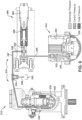
- Fig. 2 shows a multi-cross-sectional and schematic view of the pump system 112 in a normal operating state
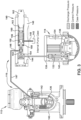
- FIG. 3 shows a multi-cross-sectional and schematic view of the pump system 112 in an overheated state.
- Fig. 4 shows an enlarged cross-sectional perspective view of a portion of the fluid-operated control 116 and the thermally-responsive control component 130.
- Fig. 5 illustrates a hydraulic circuit diagram of the pump system 112.
- the pump 114 is a variable displacement axial piston pump.
- the pump 114 is a type of positive displacement machine in which mechanical input power is converted to fluid power via the motion of pistons 132 within a cylinder block 134.
- a drive shaft 135, which may be coupled to a prime mover (e.g., aircraft engine) effects rotation of the cylinder block 134 about the longitudinal axis of the pump.
- the pistons 132 are housed within the cylinder block 134 so that the rotation of the cylinder block causes the pistons 132 to also revolve about the longitudinal axis. As the pistons 132 complete each revolution, the piston shoes sit on a thin fluid film bearing between the piston shoes and a tiltable swashplate 136..
- the pistons 132 are forced to reciprocate axially as they complete a full revolution about the longitudinal axis.
- fluid is drawn in via an inlet port 137 ( Fig. 5 ) in a port plate 138, and expelled via a discharge port 139 ( Fig. 5 ) in the port plate 138.
- the displacement of the pump is a measure of the total fluid volume that is displaced during one full revolution of the drive shaft 135.
- the displacement of the pump is manipulated by varying the angle of the swashplate 136, and thus changing the amount of axial reciprocation by each piston 132 as it completes a full revolution.
- the pump 114 is a pressure-compensated variable displacement axial piston pump in which the fluid-operated control 116 includes a pressure compensation valve assembly 140, or pressure compensator, and a control piston 142 that is operative to tilt the swashplate 136.
- the control piston 142 is operative in response to a control fluid pressure from the pressure compensator 140 to vary the angle of the swashplate 136 and thus the displacement of the pump 114.
- the displacement may be varied to achieve a designated pressure at the pump discharge port 139.
- the control piston 142 and swashplate 136 are contained within a pump case 143 that is the same pump case containing the rotating pistons 132 and cylinder block 134.
- the pressure compensation valve assembly 140 is mounted on or in the pump case 143; however, the pressure compensation valve assembly also may be located remotely from the pump case 143.
- the pressure compensation valve assembly 140 receives pump discharge fluid via an inlet port 144 of the valve and controls the flow of the pump discharge fluid through the valve as a control fluid exiting an outlet port 146 of the valve at a control pressure.
- the control pressure is communicated to the control piston 142 via a control line 147.
- the control piston 142 is configured as an off-stroke biased piston (also 142) which is configured to bias the swashplate 136 toward its minimum displacement (e.g., off-stroke) position. If the pressure compensation valve assembly 140 senses that the discharge pressure has dropped below the designated or setpoint pressure, the valve assembly 140 allows less control fluid to reach the off-stroke bias piston 142.
- valve assembly 140 senses that the discharge pressure has exceeded the designated pressure, the valve assembly 140 allows more control fluid to reach the off-stroke bias piston 142. This increases the force on the off-stroke bias piston 142, thereby decreasing the displacement of the pump 114 until the desired pressure is achieved.
- the pump displacement may be varied in this way between its minimum displacement and its maximum displacement.
- the pressure compensation valve assembly 140 includes a valve body 148 having the inlet 144 fluidly connected to the discharge pressure of the pump 114, the outlet 146 fluidly connected to the control piston 142 via control line 147, and a passage 149 fluidly connecting an internal cavity 150 of the valve to internal pump case pressure or other reference pressure.
- the pressure compensation valve assembly 140 contains an axially slidable compensator spool 152 disposed within a compensator sleeve 154, and a compensator spring 156 having at one end a compensator spring guide 158 that is operatively coupled to the compensator spool 152 for movement thereof.
- the opposite forces on the compensator spool 152 provided by the discharge pressure acting on one side of the compensator spool 152 and the compensator spring 156 acting on the opposite side of the spool 152 causes the compensator spool to move in the valve body 148 and relative to the sleeve 154 to vary a size of a variable orifice between the compensator inlet 144 and compensator outlet 146.
- the pressure compensator 140 maintains a constant internal pressure drop across the variable orifice by automatically adjusting volume flow rate delivered to the variable orifice from the flow supply in response to changing pressure drop between the compensator inlet 144 and compensator outlet 146.
- a compensator spring seat 160 At an opposite end of the compensator spring 156 is a compensator spring seat 160, in which the position of the spring seat 160 is adjustable via an adjuster screw 162.
- the adjuster screw 162 can be screwed in or out of the valve body 148 to change the spring seat position to manipulate the spring force that is acting on one side of the compensator spool 152, and thus the desired output pressure of the pump 114.
- the thermally-responsive control component 130 made with the thermally-responsive material is disposed within the pressure compensation valve assembly 140 and thus forms a component thereof.
- the thermally-responsive control component 130 is formed as thermally-responsive spacer (also 130) toward one end of the compensator spring 156, such as between the spring seat 160 and the adjuster screw 162.
- the adjuster screw 162 may have an adjuster plug 163 at one end thereof to sealingly plug the internal cavity 150 of the valve body, such as with a suitable seal.
- the thermally-responsive spacer 130 may include a forwardly projecting portion 131a for being received within the spring seat 160 and/or the spring 156.
- the thermally-responsive spacer 130 also may contain an internal passage 131b which communicates flow to the adjuster plug 163 and which may increase surface area of the spacer 130 that is exposed to fluid temperature to facilitate heat transfer.
- the thermally-responsive material of the spacer 130 is a eutectic material that melts at a preset activation temperature (e.g., eutectic melting point).
- the activation temperature may be chosen based on the chemistry of the material (e.g., metal alloy) such that the eutectic spacer 130 melts at a temperature less than the maximum operating temperature of the system hydraulic fluid, such as at those activation temperature values described above.
- the eutectic spacer 130 may include Indalloy86, Indalloy 103, or any other suitable material or combination of materials.
- the eutectic spacer 130 remains in a solid state.
- the pump discharge pressure acts on the left side of the compensator spool 152 against the force supplied by the spring 156. This balancing of forces on opposite sides of the spool 152 regulates the flow of control circuit fluid across the variable orifice and through compensator sleeve 154 to the control piston 142.
- the pressure compensator 140 is able maintain a regulated discharge pressure.
- an internal failure of the pump 114 can cause a significant amount of heat to be added to the hydraulic fluid, either through an act of friction, or by internal, recirculating, leakage from high pressure to low pressure.
- This heat addition may rapidly heat the fluid exiting the pump via the discharge port 139 and/or case drain port which is routed to heat exchanger 22.
- the overheated fluid is in thermal communication with the eutectic spacer 130.
- the eutectic spacer 130 is located at an end portion of the internal cavity 150 that contains fluid at the pump case pressure, and the overheated fluid circulates through the internal cavity 150 containing the eutectic spacer 130.
- the thermally-responsive control component 130 e.g., eutectic spacer
- the fluid-operated control 116 e.g. pressure compensator 140 and/or control piston 142
- the eutectic spacer 130 in the illustrated embodiment can quickly melt away at its activation temperature (e.g., melting point) before the maximum operation temperature of the hydraulic fluid is reached.
- the eutectic spacer 130 melts away, it allows an end of the spring 156 and/or the compensator spring seat 160 to shift away from the spool 152 and seat itself against the adjuster plug 163.
- the setpoint pressure of the pump is greatly reduced because the compensator spool 152 is allowed to shift to the right, thereby reducing pump output pressure.
- the reduced output pressure may enable the pump 114 to operate while reducing the failure friction and/or leakage to a level that does not increase the fluid temperature to an unacceptable level.
- Such an exemplary pump system 112 is intrinsically incapable of producing fluid temperatures that exceed a threshold value because all the components needed for the pressure and heat reduction to occur, are also required to successfully regulate the pump pressure during normal operation. Therefore, if the pump 114 is operating normally before a usage cycle, it is known that the prevention mechanism is operational.
- the exemplary pump system 112 also is less complex and more reliable than conventional systems that rely on temperature sensors and software control.
- the exemplary pump system 112 maintains operation of the pump system after the eutectic spacer 130 has melted by containing the hydraulic fluid to within the pump circuit. This is an improvement over conventional pump case fuse plug designs in which the hydraulic fluid is traditionally discharged out of the system and dumped overboard.
- the exemplary pressure compensator 140 with thermally-responsive control component 130 may be easily retrofittable to conventional pump designs.
- FIG. 6 another exemplary embodiment of a pump system 212 including a pump 214, a fluid-operated control 216, and a thermally-responsive control component 230 is shown.
- the pump system 212 is substantially similar to the above-referenced pump systems 12, 112, and consequently the same reference numerals but in the 200-series are used to denote structures corresponding to similar structures in the pump systems 12, 112, 212.
- the foregoing description of the pump system 12, 112 is equally applicable to the pump system 212, except as noted below. It is also understood that aspects of the pump systems 12, 112, 212 may be substituted for one another or used in conjunction with one another where applicable.
- the pump 214 in the illustrated embodiment is a pressure-compensated variable displacement axial piston pump in which the fluid-operated control 216 includes a pressure compensation valve assembly 240 and a control piston 242 operative with a swashplate 236.
- the pump 214 in the embodiment of FIG. 2 is configured such that the pump displacement defaults to minimum displacement.
- the pump 214 has re-routed the control line 247 pressure to the opposite side of the swashplate 236 to an on-stroke biased piston (also 242). This causes the unit to increase its displacement when the displacement control piston 242 is pressurized.
- the normal operating state of the pump 214 is essentially similar to that of the pump 114.
- the thermally-responsive control component 230 made with the thermally-responsive material is formed as eutectic plug (also 230) that is placed into the control line 247, or control pressure routing.
- the eutectic material and activation temperature may be substantially the same as that described above for the eutectic spacer 130.
- the eutectic plug 230 may plug a passage 249 to pump case 243, for example. When an over-temperature event occurs that raises the temperature of the eutectic plug 230 to its activation temperature, the eutectic melts away, thereby venting the control pressure into the pump case 243.
- the pump 214 Without control pressure directly connected to pump case pressure, the pump 214 defaults to a decreased output pressure, and reduces its heat generating capability.
- the eutectic plug 230 is configured to cooperate with the fluid-operated control 216 to cause a decrease in pump displacement.
- the venting of control pressure to the pump case 243 enables the pump system 212 to remain operational.
- the melting of the eutectic plug 230 can be detected during pressure performance tests prior to the next usage cycle.
- FIG. 7 another exemplary embodiment of a pump system 312 including a pump (not shown), a fluid-operated control (not shown), and a thermally-responsive control component 330 is shown.
- the pump system 312 is substantially similar to the above-referenced pump system 112, and consequently the same reference numerals but in the 300-series are used to denote structures corresponding to similar structures in the pump systems 112, 312.
- the foregoing description of the pump systems 12, 112, and 212 is equally applicable to the pump system 312, except as noted below. It is also understood that aspects of the pump systems 12, 112, 212 and 312 may be substituted for one another or used in conjunction with one another where applicable.
- the pump in the illustrated embodiment is a pressure-compensated variable displacement axial piston pump in which the fluid-operated control includes a pressure compensation valve (not shown) and a control piston (not shown) operative with a swashplate (not shown).
- the pump 314 similarly to the pump 114, the pump 314 includes a port plate 338 and a port cap 338b.
- the cylinder block (not shown) interfaces against a mating surface of the stationary port plate 338.
- the inlet port (not shown) and outlet port 339 of the pump pass through different parts of the sliding interface between the cylinder block and port plate 338.
- the port plate 338 may have two semi-circular kidney ports that allow inlet of the operating fluid and exhaust of the outlet fluid respectively.
- the thermally-responsive control component 330 made with the thermally-responsive material is formed as a plug, pin or ring made with a thermal expansion material and which is located between the port plate 338 and the port cap 338b.
- the thermal expansion material of the component 330 is configured to expand by a prescribed amount in a particular direction (e.g., axially) at a prescribed activation temperature.
- the amount of thermal expansion of the material is such that the port plate 338 is separated from the port cap 338b to form a leakage gap 341.
- the leakage gap 341 is large enough to greatly reduce pump discharge pressure and heat generation.
- the thermal expansion material of the component 330 may be a high coefficient of thermal expansion material, such as Polyether etherketone (PEEK).
- the thermally-responsive control component 330 may be made with a shape memory material (e.g., shape memory alloy or polymer) (e.g., Nitinol - nickel-titanium alloy) that activates at a preset temperature to expand or transform in a way that is sufficient to form the leakage gap 341.
- shape memory material e.g., shape memory alloy or polymer
- Nitinol - nickel-titanium alloy e.g., Nitinol - nickel-titanium alloy
- FIG. 8 another exemplary embodiment of a pump system 412 including a pump 414, a fluid-operated control 416, and one or more thermally-responsive control components 430a, 430b is shown.
- the pump system 412 is substantially similar to the above-referenced pump system 112, and consequently the same reference numerals but in the 400-series are used to denote structures corresponding to similar structures in the pump systems 112, 412.
- the foregoing description of the pump systems 12, 112, 212, and 312 is equally applicable to the pump system 412, except as noted below. It is also understood that aspects of the pump systems 12, 112, 212, 312 and 412 may be substituted for one another or used in conjunction with one another where applicable.
- the pump 414 in the illustrated embodiment is a pressure-compensated variable displacement axial piston pump in which the fluid-operated control 416 includes a pressure compensation valve assembly 440 and a control piston 442 operative with a swashplate 436.
- the operation of the pump 414 in a normal operating state is the same as that of the pump 114 described above.
- the thermally-responsive control component 430a and/or 430b is made with the thermally-responsive material and may be formed as a spring, an actuator, or any other suitable force-generating component that is made with thermally-responsive material.
- the thermally-responsive material is a shape memory material which forms a shape memory component (also 430a, 430b).
- the shape memory material may be any suitable material capable of providing the desired force (e.g., spring or actuation force).
- the shape memory material may be Nitinol.
- the shape-memory component 430a, 430b can be transformed to expand or contract when cold, but returns to its pre-transformed ("remembered") shape when heated to its preset activation temperature.
- the shape memory component 430a may cooperate with the pressure compensator 440 to alter the compensator setpoint pressure and/or the shape memory component 430b may cooperate with the control piston 442 to apply force to the swashplate 436 when the shape memory material reaches or exceeds its activation temperature. If the pressure is reduced, heat generating capability of the pump also will be reduced.
- the shape memory component 430a is formed as a spring that is used as the compensator spring in the pressure compensation valve assembly 440.
- the shape memory compensator spring may be configured to contract in length when heated to its activation temperature to thereby reduce output pressure of the pump.
- the shape memory component 430a may be a separate component to the compensator spring that may act to push on the compensator spool 452 toward the spring when activated, thereby achieving the same result of reducing pump pressure.
- the shape memory component 430b may be used to alter the angle of the swashplate 436.
- the shape memory component 430b could be implemented as a spring in the on-stroke bias piston 442b and could be configured to contract in length when heated to its activation temperature.
- the shape memory component 430b could be implemented as an expanding device on the side, or inside, of the off-stroke bias piston 442. Either way, the pump output pressure is reduced.
- the overheat prevention mechanism includes a thermally-responsive control component made with a thermally-responsive material.
- the thermally-responsive control component is located in the pump system such that the thermally-responsive material is in thermal communication with the system fluid for effecting a change in temperature of the thermally-responsive material.
- the thermally-responsive material is configured to have an activation temperature that is a predefined amount less than a maximum operating temperature of the system fluid.
- the thermally-responsive control component is configured to cooperate with a pump control mechanism in the system to decrease pump output pressure in response to the thermally-responsive material being heated by the fluid to a temperature that is equal to or greater than the activation temperature of the thermally-responsive material.
- a pump system includes: a pump for pumping fluid; a fluid-operated control fluidly connected to the pump and configured to increase or decrease pump displacement in response to a fluid pressure of the system being communicated to the fluid-operated control; and a thermally-responsive control component made with a thermally-responsive material, the thermally-responsive control component being located in the pump system such that the thermally-responsive material is in thermal communication with the fluid flowing through the pump system for effecting a change in temperature of the thermally-responsive material; wherein the thermally-responsive material is configured to have an activation temperature that is a predefined amount less than a maximum operating temperature of the fluid flowing through the pump system; and wherein the thermally-responsive control component is configured to cooperate with the fluid-operated control to cause a decrease in pump output pressure in response to the thermally-responsive material being heated by the fluid to a temperature that is equal to or greater than the activation temperature of the thermally-responsive material, and wherein the pump system can remain operational after the thermally-responsive material has reached or exceeded
- Embodiments may include one or more of the following additional features, separately or in any combination.
- the fluid-operated control includes a valve assembly that receives fluid downstream from the pump at a discharge pressure.
- the valve assembly in response to the discharge pressure, the valve assembly outputs fluid at a control pressure via a control fluid communication line that is operative to increase or decrease pump displacement.
- the thermally-responsive control component is located in the valve assembly and/or is located in the control fluid communication line.
- the fluid-operated control further includes a control actuator fluidly connected to the control fluid communication line downstream of the valve assembly for receiving fluid at the control pressure, the control actuator being operative to increase or decrease pump displacement in response to the control pressure.
- the thermally-responsive control component is located in the control actuator.
- the thermally-responsive control component is located between a source of pressurized-fluid and a pump case containing fluid at a case pressure that is lower than a pressure of the pressurized-fluid.
- the thermally-responsive control component when the thermally-responsive material is heated by the fluid to reach or exceed the activation temperature of the thermally-responsive material, the thermally-responsive control component is operative to open a leak path between the source of pressurized-fluid and the pump case to allow the fluid to leak into the pump case.
- the thermally-responsive material is in direct contact with fluid flowing through the pump system.
- the thermally-responsive material is a phase transition material.
- the phase transition material is a eutectic alloy.
- the phase transition material is a shape memory material.
- the thermally-responsive control component is a spacer, a plug, a switch, an actuator, a spring, an expander, or a support.
- the fluid-operated control includes a control actuator and a pressure compensation valve assembly
- the pressure compensation valve assembly comprising: a valve body having an inlet in fluid communication with a discharge port of the pump for communicating a discharge pressure of the pump to the pressure compensation valve assembly, and an outlet in fluid communication with the control actuator for communicating a control pressure to the control actuator; a compensator spool movable in the valve body between the inlet and the outlet; and a compensator spring configured to apply a biasing force against one side of the compensatorspool.
- the biasing force of the compensator spring counteracts the discharge pressure exerted against an opposite side of the compensator spool, and wherein the compensator spool moves between the inlet and the outlet in response to opposing forces exerted on the compensator spool by the biasing spring on the one side and the discharge pressure on the opposite side to control fluid exiting the outlet at the control pressure and being received by the control actuator, the control actuator being operative to increase or decrease pump displacement in response to the control pressure.
- the thermally-responsive control component is located in the pressure compensation valve assembly, and is configured such that when the activation temperature of the thermally-responsive material is reached or exceeded, the thermally-responsive control component transforms to alter the biasing force of the compensator spring on the compensator spool thereby changing the control pressure in a way that the control actuator decreases pump output pressure.
- the thermally-responsive control component is formed as a spacer located at a position axially offset from an end of the compensator spring.
- transformation of the spacer at the activation temperature causes the compensator spring to relax, thereby causing displacement of the compensator spool and changing the control pressure to thereby decrease pump output pressure.
- the thermally-responsive control material of the spacer is a eutectic alloy
- the activation temperature is a eutectic melting point of the eutectic alloy, the melting point having a value in a range from 10°C to 100°C less than the maximum operating temperature of the fluid.
- the fluid-operated control includes a pressure compensator that comprises a compensator spool disposed within a compensator sleeve, a compensator spring having at one end a compensator spring guide that is in functional engagement with the compensator sleeve and at an opposite end a compensator spring seat.
- the thermally-responsive control component is a spacer made with a eutectic material which is exposed to system fluid.
- the spacer melts thereby allowing the compensator spring to extend which causes a reduction in setpoint pressure of the pump due to displacement of the compensator spool which thereby reduces pump output pressure.
- the fluid-operated control includes a control actuator and a pressure compensation valve assembly, the pressure compensation valve assembly being fluidly connected to receive fluid downstream from the pump at a discharge pressure.
- the pressure compensation valve assembly in response to the discharge pressure, is configured to output fluid at a control pressure to the control actuator via a control fluid passage, the control actuator being operative to increase or decrease pump displacement in response to the control pressure.
- the thermally-responsive control component is formed as a plug that closes a vent passage fluidly connecting the control fluid passage to a pump case, the plug being made with a eutectic alloy having a eutectic melting point as the activation temperature.
- the fluid when the eutectic alloy melts at the melting point in response to heating by fluid passing through the control fluid passage, the fluid vents to the pump case via the vent passage.
- the pump is an axial piston pump having a port plate and a port cap.
- the thermally-responsive control component is disposed between the port plate and the port cap, the thermally-responsive material being a thermal expansion material that is configured to expand by a preset amount at the activation temperature to thereby form a leak path between the port plate and the port cap that leaks fluid to a pump case, thereby causing an internal leak that reduces pump discharge pressure.
- the fluid-operated control includes a control piston that is operative against a swashplate to vary pump displacement, and a pressure compensator having a compensator set point.
- the thermally-responsive control component is a spring or actuator made with a shape memory material.
- the spring or actuator made with the shape memory material is located in the pressure compensator, such that, when reaching the activation temperature, alters a compensator setpoint pressure to decrease pump output pressure.
- the spring or actuator made with the shape memory material is located in the control piston or is operative against the swashplate, such that, when reaching the activation temperature, reduces pump output pressure.
- the pump is an axial-piston pump having a swashplate
- the fluid-operated control includes a control actuator in the form of control piston that forces the swashplate between different swashplate angles to vary the pump displacement
- the pump system forms a pump circuit including fluid conduits for receiving system fluid into the pump from a reservoir and for pumping pressurized system fluid to one or more fluid-operated consumers.
- the pump circuit includes an additional pump that is operable to receive the system fluid from the reservoir and pump the pressurized system fluid to the one or more fluid-operated actuators.
- the system fluid when a faulty component of the pump increases temperature of the fluid in the pump circuit to a level that reaches or exceeds the activation temperature of the thermally-responsive material, the system fluid remains in the pump circuit such that the pump system can remain operational via operation of the additional pump.
- transformation of the thermally-responsive control component causes the fluid-operated control to cause a decrease in pump output pressure, thereby decreasing pump output power and heat generating capacity of the pump.
- the activation of the thermally-responsive material relies on physical properties of the material (such as melting) which can be assumed to have no failure modes.
- the system prevents overheated fluid from exiting the pump.
- the system disables or reduces the power input at the source of the heat generation.
- the thermally-responsive component e.g., eutectic spacer
- the thermally-responsive component is not subjected to fluid high pressure differentials.
- the system can be checked before, during and/or after each usage cycle.
- a hydraulic system for an aircraft includes: a fluid circuit having the pump system according to any of the foregoing aspects and/or features, separately or in any combination; a reservoir; a heat exchanger in a fuel cavity of the aircraft; and one or more fluid-operated devices that receive pressurized fluid from the pump to control one or more components of the aircraft.
- a pressure compensation valve assembly for a pump system includes: a valve body having an inlet for fluid communication with a discharge port of a pump of the system for communicating a discharge pressure of the pump to the pressure compensation valve assembly, and an outlet for fluid communication with a control actuator of the system for communicating a control pressure to the control actuator; a compensator spool movable in the valve body between the inlet and the outlet; a compensator spring configured to apply a biasing force against one side of the compensator spool which counteracts the discharge pressure exerted against an opposite side of the compensator spool, and wherein the compensator spool moves between the inlet and the outlet in response to opposing forces exerted on the compensator spool by the biasing spring on the one side and the discharge pressure on the opposite side to thereby control fluid exiting the outlet at the control pressure for being received by the control actuator which is operative to increase or decrease pump displacement in response to the control pressure; and a thermally-responsive control component made with a thermally-responsive material having
- a hydraulic pump system includes a hydraulic pump and a pump pressure compensator that comprises a compensator spool and a compensator spring, and a eutectic spacer located in the pressure compensator such that the eutectic spacer is in thermal communication with system fluid, wherein when the temperature of the system fluid is elevated and increases the temperature of the eutectic spacer to its melting point, the eutectic spacer melts thereby allowing the compensator spring to extend and cause a decrease in pump output pressure.
- a eutectic plug disposed within a control pressure routing such that during an over-temperature condition, the eutectic melts away, thereby venting the control pressure into a pump case.
- a hydraulic pump system comprising a thermally expanding material disposed between a port plate and a port cap of a pump, wherein the thermally expanding material expands when heated, thereby causing an internal leak of the pump that reduces pump discharge pressure.
- a hydraulic pump system that includes a swashplate, a pressure compensator having a compensator set point, and a shape memory material that is operative to reduce pump output pressure.
- a method of decreasing pump output pressure when a fluid of the pump is overheated includes: (i) pumping the fluid with the pump and discharging pressurized discharge fluid from the pump; (ii) routing at least some of the pressurized discharge fluid to a fluid-operated control; (iii) sensing a pressure of the pressurized discharge fluid with the fluid-operated control and outputting fluid at a charge pressure from the fluid-operated control; (iv) varying pump displacement in response to the charge pressure; (v) before, during, and/or after one or more of steps (i)-(iv), sensing fluid temperature with a thermally-responsive material having an activation temperature; (vi) when the temperature of the thermally-responsive material reaches the activation temperature, trigger the fluid-operated control to cause a decrease in pump output pressure; and (vii) wherein after activation of the thermally-responsive material, the fluid is maintained within a pump circuit containing the pump.
- top,” “bottom,” “upper,” “lower,” “left,” “right,” “front,” “rear,” “forward,” “rearward,” and the like as used herein may refer to an arbitrary frame of reference, rather than to the ordinary gravitational frame of reference.
- An "operable” or “operative” connection, or a connection by which entities are “operably” or “operatively” connected is one in which the entities are connected in such a way that the entities may perform as intended.
- An operable or operative connection may be a direct connection or an indirect connection in which an intermediate entity or entities cooperate or otherwise are part of the connection or are in between the operably connected entities.
- An operable or operative connection or coupling may include the entities being integral and unitary with each other.
- An operable or operative connection may include one in which signals or physical communications may be sent or received.
Landscapes
- Engineering & Computer Science (AREA)
- General Engineering & Computer Science (AREA)
- Mechanical Engineering (AREA)
- Control Of Positive-Displacement Pumps (AREA)
- Reciprocating Pumps (AREA)
- Fluid-Pressure Circuits (AREA)
Claims (15)
- Ein Hydraulikpumpensystem (12), das Folgendes beinhaltet:eine Hydraulikpumpe mit variabler Verdrängung (114) zum Pumpen von Hydraulikflüssigkeit;eine flüssigkeitsbetriebene Steuerung (16), die mit der Hydraulikpumpe (114) in Flüssigkeitsverbindung steht und konfiguriert ist, eine Pumpenverdrängung als Reaktion darauf, dass ein Hydraulikflüssigkeitsdruck des Systems an die flüssigkeitsbetriebene Steuerung (16) kommuniziert wird, zu erhöhen oder zu verringern; undeine thermisch ansprechende Steuerkomponente (30), die mit einem thermisch ansprechenden Material hergestellt ist, wobei sich die thermisch ansprechende Steuerkomponente (30) in dem Hydraulikpumpensystem (12) befindet, sodass das thermisch ansprechende Material in thermischer Kommunikation mit der Hydraulikflüssigkeit steht, die zum Bewirken einer Temperaturänderung des thermisch ansprechenden Materials durch das Hydraulikpumpensystem (12) strömt;wobei das thermisch ansprechende Material konfiguriert ist, um eine Aktivierungstemperatur aufzuweisen, die um einen vordefinierten Betrag niedriger ist als eine maximale Betriebstemperatur der Hydraulikflüssigkeit, die durch das Hydraulikpumpensystem strömt; undwobei die thermisch ansprechende Steuerkomponente (30) konfiguriert ist, um mit der flüssigkeitsbetriebenen Steuerung (16) zusammenzuwirken, um eine Verringerung des Pumpenausgangsdrucks als Reaktion darauf zu bewirken, dass das thermisch ansprechende Material durch die Hydraulikflüssigkeit auf eine Temperatur erwärmt wird, die gleich oder höher als die Aktivierungstemperatur des thermisch ansprechenden Materials ist, und wobei das Hydraulikpumpensystem (12) betriebsfähig bleiben kann, nachdem das thermisch ansprechende Material die Aktivierungstemperatur erreicht oder überschritten hat.
- Hydraulikpumpensystem gemäß Anspruch 1, wobei die flüssigkeitsbetriebene Steuerung eine Ventilbaugruppe (140) umfasst, die stromabwärts der Hydraulikpumpe Hydraulikflüssigkeit mit einem Austrittsdruck empfängt, und wobei die Ventilbaugruppe (140), als Reaktion auf den Austrittsdruck, Hydraulikflüssigkeit mit einem Steuerdruck über eine Steuerflüssigkeitskommunikationsleitung ausgibt, die betriebswirksam ist, um die Pumpenverdrängung zu erhöhen oder zu verringern.
- Hydraulikpumpensystem gemäß Anspruch 2 oder einem anderen vorhergehenden Anspruch, wobei sich die thermisch ansprechende Steuerkomponente (30) in der Ventilbaugruppe (140) befindet und/oder sich in der Steuerflüssigkeitskommunikationsleitung befindet.
- Hydraulikpumpensystem gemäß Anspruch 2 oder einem anderen vorhergehenden Anspruch, wobei die flüssigkeitsbetriebene Steuerung (16) ferner einen Steueraktuator umfasst, der mit der Steuerflüssigkeitskommunikationsleitung stromabwärts der Ventilbaugruppe (140) in Flüssigkeitsverbindung steht, um Hydraulikflüssigkeit mit dem Steuerdruck zu empfangen, wobei der Steueraktuator betriebswirksam ist, um die Pumpenverdrängung als Reaktion auf den Steuerdruck zu erhöhen oder zu verringern; wobei sich optional die thermisch ansprechende Steuerkomponente (30) in dem Steueraktuator befindet.
- Hydraulikpumpensystem gemäß Anspruch 1 oder einem anderen vorhergehenden Anspruch, wobei sich die thermisch ansprechende Steuerkomponente (30) zwischen einer Quelle unter Druck stehender Flüssigkeit und einem Pumpengehäuse (143), das Hydraulikflüssigkeit mit einem Gehäusedruck enthält, der niedriger ist als ein Druck der unter Druck stehenden Flüssigkeit, befindet, und wobei, wenn das thermisch ansprechende Material durch die Hydraulikflüssigkeit erwärmt wird, um die Aktivierungstemperatur des thermisch ansprechenden Materials zu erreichen oder zu überschreiten, die thermisch ansprechende Steuerkomponente (30) betriebswirksam ist, um einen Leckpfad zwischen der Quelle unter Druck stehender Flüssigkeit und dem Pumpengehäuse (143) zu öffnen, damit die Hydraulikflüssigkeit in das Pumpengehäuse (143) lecken kann.
- Hydraulikpumpensystem gemäß Anspruch 1 oder einem anderen vorhergehenden Anspruch, wobei das thermisch ansprechende Material ein Phasenübergangsmaterial ist; optionali) wobei das Phasenübergangsmaterial eine eutektische Legierung ist und die Aktivierungstemperatur die eutektische Temperatur der eutektischen Legierung ist; oderii) wobei das Phasenübergangsmaterial ein Formgedächtnismaterial ist.
- Hydraulikpumpensystem gemäß Anspruch 1 oder einem anderen vorhergehenden Anspruch,
wobei die flüssigkeitsbetriebene Steuerung (16) einen Steueraktuator und eine Druckausgleichsventilbaugruppe umfasst, wobei die Druckausgleichsventilbaugruppe (140) Folgendes beinhaltet:einen Ventilkörper (148) mit einem Einlass (144), der in Flüssigkeitskommunikation mit einem Austrittsanschluss (139) der Hydraulikpumpe steht, um einen Austrittsdruck der Hydraulikpumpe an die Druckausgleichsventilbaugruppe (140) zu kommunizieren, und einem Auslass (146), der in Flüssigkeitskommunikation mit dem Steueraktuator steht, um einen Steuerdruck an den Steueraktuator zu kommunizieren;einen Kompensatorschieber (152), der in dem Ventilkörper (148) zwischen dem Einlass (144) und dem Auslass (146) beweglich ist; undeine Kompensatorfeder (156), die konfiguriert ist, um eine Vorspannkraft gegen eine Seite des Kompensatorschiebers (152) anzulegen;wobei die Vorspannkraft der Kompensatorfeder (156) dem Austrittsdruck entgegenwirkt, der gegen eine gegenüberliegende Seite des Kompensatorschiebers (152) ausgeübt wird, und wobei sich der Kompensatorschieber (152) zwischen dem Einlass (144) und dem Auslass (146) als Reaktion auf entgegengesetzte Kräfte bewegt, die durch die Vorspannfeder auf der einen Seite und den Austrittsdruck auf der gegenüberliegenden Seite auf den Kompensatorschieber (152) ausgeübt werden, um Hydraulikflüssigkeit zu steuern, die den Auslass (146) mit dem Steuerdruck verlässt und von dem Steueraktuator empfangen wird, wobei der Steueraktuator betriebswirksam ist, um die Pumpenverdrängung als Reaktion auf den Steuerdruck zu erhöhen oder zu verringern; undwobei sich die thermisch ansprechende Steuerkomponente (30) in der Druckausgleichsventilbaugruppe (140) befindet und konfiguriert ist, sodass, wenn die Aktivierungstemperatur des thermisch ansprechenden Materials erreicht oderüberschritten wird, sich die thermisch ansprechende Steuerkomponente transformiert, um die Vorspannkraft der Kompensatorfeder (156) auf dem Kompensatorschieber (152) zu verändern, wodurch der Steuerdruck in einer Weise geändert wird, dass der Steueraktuator einen Pumpenausgangsdruck verringert. - Hydraulikpumpensystem gemäß Anspruch 1 oder einem anderen vorhergehenden Anspruch, wobei die thermisch ansprechende Steuerkomponente als Abstandshalter (130) ausgebildet ist, der sich an einer Position befindet, die von einem Ende der Kompensatorfeder (156) axial versetzt ist, und wobei eine Transformation des Abstandshalters bei der Aktivierungstemperatur bewirkt, dass sich die Kompensatorfeder (156) entspannt, wodurch eine Verschiebung des Kompensatorschiebers (152) bewirkt und der Steuerdruck geändert wird, um dadurch den Pumpenausgangsdruck zu verringern; wobei optional das thermisch ansprechende Steuermaterial des Abstandshalters (130) eine eutektische Legierung ist und die Aktivierungstemperatur ein eutektischer Schmelzpunkt der eutektischen Legierung ist, wobei der Schmelzpunkt einen Wert in einem Bereich von 10 °C bis 100 °C weniger als die maximale Betriebstemperatur der Flüssigkeit aufweist.
- Hydraulikpumpensystem gemäß Anspruch 1 oder einem anderen vorhergehenden Anspruch, wobei die flüssigkeitsbetriebene Steuerung einen Druckkompensator umfasst, der einen Kompensatorschieber (152), der innerhalb einer Kompensatorhülse (154) angeordnet ist, eine Kompensatorfeder (156), die an einem Ende eine Kompensatorfederführung (158), die in funktionalem Eingriff mit der Kompensatorhülse (154) steht, und an einem gegenüberliegenden Ende einen Kompensatorfedersitz (160) aufweist, beinhaltet, und wobei die thermisch ansprechende Steuerkomponente ein Abstandshalter (130) ist, der mit einem eutektischen Material hergestellt ist, das einer Systemflüssigkeit ausgesetzt ist, wobei, wenn die Temperatur der Hydrauliksystemflüssigkeit erhöht wird, um die Aktivierungstemperatur zu erreichen, der Abstandshalter schmilzt, wodurch sich die Kompensatorfeder ausdehnen kann, was eine Reduzierung des Solldrucks der Hydraulikpumpe aufgrund der Verschiebung des Kompensatorschiebers bewirkt, der dadurch den Pumpenausgangsdruck reduziert.
- Hydraulikpumpensystem gemäß Anspruch 1 oder einem anderen vorhergehenden Anspruch,wobei die flüssigkeitsbetriebene Steuerung (216) einen Steueraktuator und eine Druckausgleichsventilbaugruppe (240) umfasst, wobei die Druckausgleichsventilbaugruppe in Flüssigkeitsverbindung steht, um Hydraulikflüssigkeit stromabwärts von der Hydraulikpumpe mit einem Austrittsdruck zu empfangen, und wobei die Druckausgleichsventilbaugruppe (240) konfiguriert ist, um als Reaktion auf den Austrittsdruck Hydraulikflüssigkeit mit einem Steuerdruck an den Steueraktuator über einen Steuerflüssigkeitsdurchgang auszugeben, wobei der Steueraktuator betriebswirksam ist, um die Pumpenverdrängung als Reaktion auf den Steuerdruck zu erhöhen oder zu verringern;wobei die thermisch ansprechende Steuerkomponente als Stopfen (230) ausgebildet ist, der einen Ablassdurchgang (249) verschließt, der den Steuerflüssigkeitsdurchgang mit einem Pumpengehäuse (243) in Flüssigkeitsverbindung bringt, wobei der Stopfen mit einer eutektischen Legierung mit einem eutektischen Schmelzpunkt als Aktivierungstemperatur hergestellt ist; undwobei, wenn die eutektische Legierung als Reaktion auf eine Erwärmung durch Hydraulikflüssigkeit, die den Steuerflüssigkeitsdurchgang durchläuft, auf dem Schmelzpunkt schmilzt, die Hydraulikflüssigkeit über den Ablassdurchgang in das Pumpengehäuse abgelassen wird.
- Hydraulikpumpensystem gemäß Anspruch 1 oder einem anderen vorhergehenden Anspruch, wobei die Hydraulikpumpe eine Axialkolbenpumpe (314) mit einer Anschlussplatte (338) und einer Anschlusskappe (338b) ist, und wobei eine thermisch ansprechende Steuerkomponente (330) zwischen der Anschlussplatte (338) und der Anschlusskappe (338b) angeordnet ist, das thermisch ansprechende Material ein Wärmeausdehnungsmaterial ist, das konfiguriert ist, um sich bei der Aktivierungstemperatur um einen voreingestellten Betrag auszudehnen, um dadurch einen Leckpfad zwischen der Anschlussplatte (338) und der Anschlusskappe (338b) auszubilden, der Hydraulikflüssigkeit zu einem Pumpengehäuse leckt, wodurch ein internes Lecken verursacht wird, das den Pumpenaustrittsdruck reduziert.
- Hydraulikpumpensystem gemäß Anspruch 1 oder einem anderen vorhergehenden Anspruch,wobei die flüssigkeitsbetriebene Steuerung (416) einen Steuerkolben, der gegen eine Taumelscheibe (436) betriebswirksam ist, um eine Pumpenverdrängung zu variieren, und einen Druckkompensator (440) mit einem Kompensator-Sollwert umfasst; wobei die thermisch ansprechende Steuerkomponente (430a, 430b) eine/ein mit einem Formgedächtnismaterial hergestellte/r Feder oder Aktuator ist;wobei (i) sich die/der mit dem Formgedächtnismaterial hergestellte Feder oder Aktuator in dem Druckkompensator (440) befindet, sodass sie/er bei Erreichen der Aktivierungstemperatur einen Kompensator-Solldruck ändert, um den Pumpenausgangsdruck zu verringern; und/oder (ii) sich die/der mit dem Formgedächtnismaterial hergestellte Feder oder Aktuator in dem Steuerkolben befindet oder gegen die Taumelscheibe (436) betriebswirksam ist, sodass sie/er bei Erreichen der Aktivierungstemperatur den Pumpenausgangsdruck reduziert.
- Hydraulikpumpensystem gemäß Anspruch 1 oder einem anderen vorhergehenden Anspruch, wobei das Hydraulikpumpensystem einen Hydraulikpumpenkreislauf (12) bildet, der Flüssigkeitskanäle (17) zum Empfangen von Hydrauliksystemflüssigkeit, aus einem Reservoir (18), in der Hydraulikpumpe und zum Pumpen von unter Druck stehender Hydrauliksystemflüssigkeit zu einem oder mehreren flüssigkeitsbetriebenen Verbrauchern (20) umfasst, und wobei der Hydraulikpumpenkreislauf (12) eine zusätzliche Hydraulikpumpe (24) umfasst, die betreibbar ist, um die Hydrauliksystemflüssigkeit aus dem Reservoir (18) zu empfangen und die unter Druck stehende Hydrauliksystemflüssigkeit zu dem einen oder den mehreren flüssigkeitsbetriebenen Aktuatoren (20) zu pumpen, und wobei, wenn eine fehlerhafte Komponente der Hydraulikpumpe die Temperatur der Hydraulikflüssigkeit in dem Pumpenkreislauf auf ein Niveau erhöht, das die Aktivierungstemperatur des thermisch ansprechenden Materials erreicht oder überschreitet, die Hydrauliksystemflüssigkeit in dem Hydraulikpumpenkreislauf verbleibt, sodass das Hydraulikpumpensystem über den Betrieb der zusätzlichen Hydraulikpumpe (24) betriebsfähig bleiben kann;
wobei optional die Hydraulikpumpe eine Axialkolbenpumpe mit einer Taumelscheibe (136) ist, und wobei die flüssigkeitsbetriebene Steuerung (16) einen Steueraktuator in Form eines Steuerkolbens (142) umfasst, der die Taumelscheibe zwischen unterschiedlichen Taumelscheibenwinkeln zwingt, die Pumpenverdrängung zu variieren. - Hydraulikpumpensystem gemäß Anspruch 1 oder einem anderen vorhergehenden Anspruch, wobei, wenn das thermisch ansprechende Material die Aktivierungstemperatur erreicht oder überschreitet, die Transformation der thermisch ansprechenden Steuerkomponente bewirkt, dass die flüssigkeitsbetriebene Steuerung eine Verringerung des Pumpenausgangsdrucks bewirkt, wodurch die Pumpenausgangsleistung und die Wärmeerzeugungskapazität der Hydraulikpumpe verringert werden.
- Ein Verfahren zum Verringern eines Ausgangsdrucks einer Hydraulikpumpe mit variabler Verdrängung (14), wenn eine Hydraulikflüssigkeit der Hydraulikpumpe überhitzt wird, das Folgendes beinhaltet:(i) Pumpen der Hydraulikflüssigkeit mit der Hydraulikpumpe mit variabler Verdrängung (14) und Austretenlassen der unter Druck stehenden Austrittsflüssigkeit aus der Hydraulikpumpe;(ii) Leiten zumindest eines Teils der unter Druck stehenden Austrittshydraulikflüssigkeit zu einer flüssigkeitsbetriebenen Steuerung (16);(iii) Erfassen eines Drucks der unter Druck stehenden Austrittshydraulikflüssigkeit mit der flüssigkeitsbetriebenen Steuerung (16) und Ausgeben von Hydraulikflüssigkeit mit einem Ladedruck von der flüssigkeitsbetriebenen Steuerung;(iv) Variieren der Pumpenverdrängung der Hydraulikpumpe (14) als Reaktion auf den Ladedruck;(v) vor, während und/oder nach einem oder mehreren der Schritte (i)-(iv), Erfassen der Hydraulikflüssigkeitstemperatur mit einem thermisch ansprechenden Material, das eine Aktivierungstemperatur aufweist;(vi) wenn die Temperatur des thermisch ansprechenden Materials die Aktivierungstemperatur erreicht, Auslösen der flüssigkeitsbetriebenen Steuerung, um eine Verringerung des Hydraulikpumpenausgangsdrucks zu bewirken; und(vii) wobei nach der Aktivierung des thermisch ansprechenden Materials die Hydraulikflüssigkeit innerhalb eines Hydraulikpumpenkreislaufs, der die Hydraulikpumpe enthält, gehalten wird.
Applications Claiming Priority (2)
| Application Number | Priority Date | Filing Date | Title |
|---|---|---|---|
| US201962903073P | 2019-09-20 | 2019-09-20 | |
| PCT/US2020/051153 WO2021055527A1 (en) | 2019-09-20 | 2020-09-17 | Pump system with over-temperature prevention |
Publications (2)
| Publication Number | Publication Date |
|---|---|
| EP4031767A1 EP4031767A1 (de) | 2022-07-27 |
| EP4031767B1 true EP4031767B1 (de) | 2023-11-01 |
Family
ID=72709860
Family Applications (1)
| Application Number | Title | Priority Date | Filing Date |
|---|---|---|---|
| EP20785639.4A Active EP4031767B1 (de) | 2019-09-20 | 2020-09-17 | Pumpensystem mit übertemperaturschutz |
Country Status (4)
| Country | Link |
|---|---|
| US (2) | US12247555B2 (de) |
| EP (1) | EP4031767B1 (de) |
| CA (1) | CA3148837A1 (de) |
| WO (1) | WO2021055527A1 (de) |
Families Citing this family (1)
| Publication number | Priority date | Publication date | Assignee | Title |
|---|---|---|---|---|
| EP4031767B1 (de) * | 2019-09-20 | 2023-11-01 | Parker-Hannifin Corporation | Pumpensystem mit übertemperaturschutz |
Citations (4)
| Publication number | Priority date | Publication date | Assignee | Title |
|---|---|---|---|---|
| EP0258680A1 (de) * | 1986-08-08 | 1988-03-09 | Sanden Corporation | Schiefscheibenverdichter mit Vorrichtung zur Hubänderung |
| US20150020759A1 (en) * | 2013-07-17 | 2015-01-22 | Hitachi Automotive Systems, Ltd, | Variable displacement pump |
| US20170218953A1 (en) * | 2016-01-29 | 2017-08-03 | Yamada Manufacturing Co., Ltd. | Variable-capacity vane pump |
| EP3088279B1 (de) * | 2013-12-27 | 2019-10-30 | Hitachi Construction Machinery Co., Ltd. | Hydraulisches antriebssystem |
Family Cites Families (24)
| Publication number | Priority date | Publication date | Assignee | Title |
|---|---|---|---|---|
| GB722864A (en) * | 1951-11-01 | 1955-02-02 | Bendix Avlation Corp | Improvements in or relating to variable displacement pumps |
| AU6079573A (en) * | 1972-10-11 | 1975-03-27 | Sperry Rand Ltd | Pressure control in hydraulic systems |
| DE3006370A1 (de) | 1980-02-20 | 1981-08-27 | Robert Bosch Gmbh, 7000 Stuttgart | Steuerventil |
| JPS59220456A (ja) * | 1983-05-27 | 1984-12-11 | Toyoda Mach Works Ltd | 動力舵取装置用流量制御装置 |
| US4537346A (en) | 1983-10-17 | 1985-08-27 | Standard-Thomson Corporation | Fail-safe oil flow control apparatus |
| JPH041499A (ja) | 1990-04-13 | 1992-01-06 | Toshiba Corp | ポンプの吐出流量制御装置 |
| US5048751A (en) * | 1990-04-16 | 1991-09-17 | Outboard Marine Corporation | Pressure and temperature relief valve and diaphragm valve |
| CA2088185C (en) | 1993-02-05 | 1999-08-31 | Clarence William Johnson | Two line pilot valve |
| US5511576A (en) | 1995-01-17 | 1996-04-30 | Amcast Industrial Corporation | Piston-type thermally activated relief device |
| JP3561366B2 (ja) * | 1996-03-29 | 2004-09-02 | サンデン株式会社 | 強制リデュース装置及びそれを備えた圧縮機 |
| JPH10176660A (ja) | 1996-12-13 | 1998-06-30 | Zexel Corp | 可変容量型斜板式圧縮機 |
| JP2000320465A (ja) * | 1999-05-10 | 2000-11-21 | Saginomiya Seisakusho Inc | 容量可変型圧縮機用制御弁 |
| US6186168B1 (en) | 1999-05-19 | 2001-02-13 | Veritek Ngv, Corp | Pressure Regulator |
| US7444209B2 (en) * | 2006-10-26 | 2008-10-28 | Honeywell International Inc. | Miniature cooling device |
| JP4924464B2 (ja) | 2008-02-05 | 2012-04-25 | 株式会社豊田自動織機 | 斜板式圧縮機 |
| US20110139270A1 (en) | 2009-12-11 | 2011-06-16 | Veilleux Jr Leo J | Thermal switched cooling orifice for actuation systems |
| US9133952B2 (en) * | 2011-04-01 | 2015-09-15 | Rostra Vernatherm LLC | Thermostatic bypass valve with a unique valve seat |
| US20130226415A1 (en) | 2012-02-28 | 2013-08-29 | Caterpillar Inc. | Continuously Productive Machine During Hydraulic System Overheat Condition |
| JP2014119107A (ja) * | 2012-12-19 | 2014-06-30 | Kubota Corp | 油圧サーボ装置 |
| DE102015000805B3 (de) * | 2015-01-22 | 2016-01-21 | Nidec Gpm Gmbh | Regelbare Kühlmittelpumpe |
| JP6612610B2 (ja) * | 2015-12-17 | 2019-11-27 | ナブテスコ株式会社 | 流体圧ポンプおよび流体圧システム |
| IT201600069965U1 (it) * | 2016-07-05 | 2018-01-05 | Fluid O Tech Srl | Pompa idraulica e rispettiva valvola multifunzione. |
| EP3425213B1 (de) * | 2017-07-03 | 2020-11-25 | LEONARDO S.p.A. | Sicherheitsventil und verfahren zur steuerung eines hydraulischen kreislaufs |
| EP4031767B1 (de) * | 2019-09-20 | 2023-11-01 | Parker-Hannifin Corporation | Pumpensystem mit übertemperaturschutz |
-
2020
- 2020-09-17 EP EP20785639.4A patent/EP4031767B1/de active Active
- 2020-09-17 US US17/624,966 patent/US12247555B2/en active Active
- 2020-09-17 CA CA3148837A patent/CA3148837A1/en active Pending
- 2020-09-17 WO PCT/US2020/051153 patent/WO2021055527A1/en not_active Ceased
-
2025
- 2025-02-12 US US19/051,273 patent/US12601334B2/en active Active
Patent Citations (4)
| Publication number | Priority date | Publication date | Assignee | Title |
|---|---|---|---|---|
| EP0258680A1 (de) * | 1986-08-08 | 1988-03-09 | Sanden Corporation | Schiefscheibenverdichter mit Vorrichtung zur Hubänderung |
| US20150020759A1 (en) * | 2013-07-17 | 2015-01-22 | Hitachi Automotive Systems, Ltd, | Variable displacement pump |
| EP3088279B1 (de) * | 2013-12-27 | 2019-10-30 | Hitachi Construction Machinery Co., Ltd. | Hydraulisches antriebssystem |
| US20170218953A1 (en) * | 2016-01-29 | 2017-08-03 | Yamada Manufacturing Co., Ltd. | Variable-capacity vane pump |
Also Published As
| Publication number | Publication date |
|---|---|
| CA3148837A1 (en) | 2021-03-25 |
| US20220268272A1 (en) | 2022-08-25 |
| US12601334B2 (en) | 2026-04-14 |
| US12247555B2 (en) | 2025-03-11 |
| US20250179999A1 (en) | 2025-06-05 |
| WO2021055527A1 (en) | 2021-03-25 |
| EP4031767A1 (de) | 2022-07-27 |
Similar Documents
| Publication | Publication Date | Title |
|---|---|---|
| KR101448338B1 (ko) | 냉각제 회로용 페일-세이프 회전 액추에이터 | |
| EP2864607B1 (de) | Flüssigkeitsmengenregler | |
| US12601334B2 (en) | Variable displacement hydraulic pump system with over-temperature prevention | |
| US8490885B2 (en) | Integrated freeze protection and pressure relief valve | |
| US10794436B2 (en) | Hydraulic brake and disconnect for rotational machines | |
| EP2310692B1 (de) | Flusssteuerung | |
| CN110520634B (zh) | 用于调节液力机器的设备 | |
| KR20090042805A (ko) | 유압 장치의 하류에 연결된 냉각기를 위한 바이 패스 밸브 | |
| KR20150136590A (ko) | 유압-구동 서모스탯 | |
| WO2013126374A1 (en) | Valve with integrated wax motor bypass fail safe | |
| CN117396678A (zh) | 用于具有顺桨位置的涡轮发动机螺旋桨的电液桨距控制系统 | |
| US20110139270A1 (en) | Thermal switched cooling orifice for actuation systems | |
| US10935052B2 (en) | Safety valve and method for controlling a hydraulic circuit | |
| JP6321679B2 (ja) | 少なくとも1つの油圧負荷を温度に従って制御するための弁 | |
| EP3257746B1 (de) | Elektrische hydrostatische aktuatoren | |
| EP3654130B1 (de) | Wärmewachs-bypass-ventil mit verwendung eines starren dichtungsträgers | |
| US20200173742A1 (en) | Thermal wax bypass valve utilizing boot with wax separators | |
| EP3654129B1 (de) | Teilkreisförmige ventiloberfläche für ein wachsventil | |
| EP2829741B1 (de) | Fluiddruckregelungssystem | |
| EP3643953B1 (de) | Feueraktiviertes kühlfluidventil | |
| CN122040487A (zh) | 燃油系统 |
Legal Events
| Date | Code | Title | Description |
|---|---|---|---|
| STAA | Information on the status of an ep patent application or granted ep patent |
Free format text: STATUS: UNKNOWN |
|
| STAA | Information on the status of an ep patent application or granted ep patent |
Free format text: STATUS: THE INTERNATIONAL PUBLICATION HAS BEEN MADE |
|
| PUAI | Public reference made under article 153(3) epc to a published international application that has entered the european phase |
Free format text: ORIGINAL CODE: 0009012 |
|
| STAA | Information on the status of an ep patent application or granted ep patent |
Free format text: STATUS: REQUEST FOR EXAMINATION WAS MADE |
|
| 17P | Request for examination filed |
Effective date: 20220106 |
|
| AK | Designated contracting states |
Kind code of ref document: A1 Designated state(s): AL AT BE BG CH CY CZ DE DK EE ES FI FR GB GR HR HU IE IS IT LI LT LU LV MC MK MT NL NO PL PT RO RS SE SI SK SM TR |
|
| DAV | Request for validation of the european patent (deleted) | ||
| DAX | Request for extension of the european patent (deleted) | ||
| GRAP | Despatch of communication of intention to grant a patent |
Free format text: ORIGINAL CODE: EPIDOSNIGR1 |
|
| STAA | Information on the status of an ep patent application or granted ep patent |
Free format text: STATUS: GRANT OF PATENT IS INTENDED |
|
| INTG | Intention to grant announced |
Effective date: 20230508 |
|
| P01 | Opt-out of the competence of the unified patent court (upc) registered |
Effective date: 20230524 |
|
| GRAS | Grant fee paid |
Free format text: ORIGINAL CODE: EPIDOSNIGR3 |
|
| GRAA | (expected) grant |
Free format text: ORIGINAL CODE: 0009210 |
|
| STAA | Information on the status of an ep patent application or granted ep patent |
Free format text: STATUS: THE PATENT HAS BEEN GRANTED |
|
| AK | Designated contracting states |
Kind code of ref document: B1 Designated state(s): AL AT BE BG CH CY CZ DE DK EE ES FI FR GB GR HR HU IE IS IT LI LT LU LV MC MK MT NL NO PL PT RO RS SE SI SK SM TR |
|
| REG | Reference to a national code |
Ref country code: GB Ref legal event code: FG4D |
|
| REG | Reference to a national code |
Ref country code: CH Ref legal event code: EP |
|
| REG | Reference to a national code |
Ref country code: DE Ref legal event code: R096 Ref document number: 602020020366 Country of ref document: DE |
|
| REG | Reference to a national code |
Ref country code: IE Ref legal event code: FG4D |
|
| REG | Reference to a national code |
Ref country code: LT Ref legal event code: MG9D |
|
| REG | Reference to a national code |
Ref country code: NL Ref legal event code: MP Effective date: 20231101 |
|
| PG25 | Lapsed in a contracting state [announced via postgrant information from national office to epo] |
Ref country code: GR Free format text: LAPSE BECAUSE OF FAILURE TO SUBMIT A TRANSLATION OF THE DESCRIPTION OR TO PAY THE FEE WITHIN THE PRESCRIBED TIME-LIMIT Effective date: 20240202 |
|
| PG25 | Lapsed in a contracting state [announced via postgrant information from national office to epo] |
Ref country code: IS Free format text: LAPSE BECAUSE OF FAILURE TO SUBMIT A TRANSLATION OF THE DESCRIPTION OR TO PAY THE FEE WITHIN THE PRESCRIBED TIME-LIMIT Effective date: 20240301 |
|
| PG25 | Lapsed in a contracting state [announced via postgrant information from national office to epo] |
Ref country code: LT Free format text: LAPSE BECAUSE OF FAILURE TO SUBMIT A TRANSLATION OF THE DESCRIPTION OR TO PAY THE FEE WITHIN THE PRESCRIBED TIME-LIMIT Effective date: 20231101 |
|
| REG | Reference to a national code |
Ref country code: AT Ref legal event code: MK05 Ref document number: 1627478 Country of ref document: AT Kind code of ref document: T Effective date: 20231101 |
|
| PG25 | Lapsed in a contracting state [announced via postgrant information from national office to epo] |
Ref country code: NL Free format text: LAPSE BECAUSE OF FAILURE TO SUBMIT A TRANSLATION OF THE DESCRIPTION OR TO PAY THE FEE WITHIN THE PRESCRIBED TIME-LIMIT Effective date: 20231101 |
|
| PG25 | Lapsed in a contracting state [announced via postgrant information from national office to epo] |
Ref country code: AT Free format text: LAPSE BECAUSE OF FAILURE TO SUBMIT A TRANSLATION OF THE DESCRIPTION OR TO PAY THE FEE WITHIN THE PRESCRIBED TIME-LIMIT Effective date: 20231101 |
|
| PG25 | Lapsed in a contracting state [announced via postgrant information from national office to epo] |
Ref country code: ES Free format text: LAPSE BECAUSE OF FAILURE TO SUBMIT A TRANSLATION OF THE DESCRIPTION OR TO PAY THE FEE WITHIN THE PRESCRIBED TIME-LIMIT Effective date: 20231101 |
|
| PG25 | Lapsed in a contracting state [announced via postgrant information from national office to epo] |
Ref country code: NL Free format text: LAPSE BECAUSE OF FAILURE TO SUBMIT A TRANSLATION OF THE DESCRIPTION OR TO PAY THE FEE WITHIN THE PRESCRIBED TIME-LIMIT Effective date: 20231101 Ref country code: LT Free format text: LAPSE BECAUSE OF FAILURE TO SUBMIT A TRANSLATION OF THE DESCRIPTION OR TO PAY THE FEE WITHIN THE PRESCRIBED TIME-LIMIT Effective date: 20231101 Ref country code: IS Free format text: LAPSE BECAUSE OF FAILURE TO SUBMIT A TRANSLATION OF THE DESCRIPTION OR TO PAY THE FEE WITHIN THE PRESCRIBED TIME-LIMIT Effective date: 20240301 Ref country code: GR Free format text: LAPSE BECAUSE OF FAILURE TO SUBMIT A TRANSLATION OF THE DESCRIPTION OR TO PAY THE FEE WITHIN THE PRESCRIBED TIME-LIMIT Effective date: 20240202 Ref country code: ES Free format text: LAPSE BECAUSE OF FAILURE TO SUBMIT A TRANSLATION OF THE DESCRIPTION OR TO PAY THE FEE WITHIN THE PRESCRIBED TIME-LIMIT Effective date: 20231101 Ref country code: BG Free format text: LAPSE BECAUSE OF FAILURE TO SUBMIT A TRANSLATION OF THE DESCRIPTION OR TO PAY THE FEE WITHIN THE PRESCRIBED TIME-LIMIT Effective date: 20240201 Ref country code: AT Free format text: LAPSE BECAUSE OF FAILURE TO SUBMIT A TRANSLATION OF THE DESCRIPTION OR TO PAY THE FEE WITHIN THE PRESCRIBED TIME-LIMIT Effective date: 20231101 Ref country code: PT Free format text: LAPSE BECAUSE OF FAILURE TO SUBMIT A TRANSLATION OF THE DESCRIPTION OR TO PAY THE FEE WITHIN THE PRESCRIBED TIME-LIMIT Effective date: 20240301 |
|
| PG25 | Lapsed in a contracting state [announced via postgrant information from national office to epo] |
Ref country code: SE Free format text: LAPSE BECAUSE OF FAILURE TO SUBMIT A TRANSLATION OF THE DESCRIPTION OR TO PAY THE FEE WITHIN THE PRESCRIBED TIME-LIMIT Effective date: 20231101 Ref country code: RS Free format text: LAPSE BECAUSE OF FAILURE TO SUBMIT A TRANSLATION OF THE DESCRIPTION OR TO PAY THE FEE WITHIN THE PRESCRIBED TIME-LIMIT Effective date: 20231101 Ref country code: PL Free format text: LAPSE BECAUSE OF FAILURE TO SUBMIT A TRANSLATION OF THE DESCRIPTION OR TO PAY THE FEE WITHIN THE PRESCRIBED TIME-LIMIT Effective date: 20231101 Ref country code: NO Free format text: LAPSE BECAUSE OF FAILURE TO SUBMIT A TRANSLATION OF THE DESCRIPTION OR TO PAY THE FEE WITHIN THE PRESCRIBED TIME-LIMIT Effective date: 20240201 Ref country code: LV Free format text: LAPSE BECAUSE OF FAILURE TO SUBMIT A TRANSLATION OF THE DESCRIPTION OR TO PAY THE FEE WITHIN THE PRESCRIBED TIME-LIMIT Effective date: 20231101 Ref country code: HR Free format text: LAPSE BECAUSE OF FAILURE TO SUBMIT A TRANSLATION OF THE DESCRIPTION OR TO PAY THE FEE WITHIN THE PRESCRIBED TIME-LIMIT Effective date: 20231101 |
|
| PG25 | Lapsed in a contracting state [announced via postgrant information from national office to epo] |
Ref country code: DK Free format text: LAPSE BECAUSE OF FAILURE TO SUBMIT A TRANSLATION OF THE DESCRIPTION OR TO PAY THE FEE WITHIN THE PRESCRIBED TIME-LIMIT Effective date: 20231101 |
|
| PG25 | Lapsed in a contracting state [announced via postgrant information from national office to epo] |
Ref country code: CZ Free format text: LAPSE BECAUSE OF FAILURE TO SUBMIT A TRANSLATION OF THE DESCRIPTION OR TO PAY THE FEE WITHIN THE PRESCRIBED TIME-LIMIT Effective date: 20231101 |
|
| PG25 | Lapsed in a contracting state [announced via postgrant information from national office to epo] |
Ref country code: SK Free format text: LAPSE BECAUSE OF FAILURE TO SUBMIT A TRANSLATION OF THE DESCRIPTION OR TO PAY THE FEE WITHIN THE PRESCRIBED TIME-LIMIT Effective date: 20231101 |
|
| PG25 | Lapsed in a contracting state [announced via postgrant information from national office to epo] |
Ref country code: SM Free format text: LAPSE BECAUSE OF FAILURE TO SUBMIT A TRANSLATION OF THE DESCRIPTION OR TO PAY THE FEE WITHIN THE PRESCRIBED TIME-LIMIT Effective date: 20231101 Ref country code: SK Free format text: LAPSE BECAUSE OF FAILURE TO SUBMIT A TRANSLATION OF THE DESCRIPTION OR TO PAY THE FEE WITHIN THE PRESCRIBED TIME-LIMIT Effective date: 20231101 Ref country code: IT Free format text: LAPSE BECAUSE OF FAILURE TO SUBMIT A TRANSLATION OF THE DESCRIPTION OR TO PAY THE FEE WITHIN THE PRESCRIBED TIME-LIMIT Effective date: 20231101 Ref country code: EE Free format text: LAPSE BECAUSE OF FAILURE TO SUBMIT A TRANSLATION OF THE DESCRIPTION OR TO PAY THE FEE WITHIN THE PRESCRIBED TIME-LIMIT Effective date: 20231101 Ref country code: DK Free format text: LAPSE BECAUSE OF FAILURE TO SUBMIT A TRANSLATION OF THE DESCRIPTION OR TO PAY THE FEE WITHIN THE PRESCRIBED TIME-LIMIT Effective date: 20231101 Ref country code: CZ Free format text: LAPSE BECAUSE OF FAILURE TO SUBMIT A TRANSLATION OF THE DESCRIPTION OR TO PAY THE FEE WITHIN THE PRESCRIBED TIME-LIMIT Effective date: 20231101 |
|
| REG | Reference to a national code |
Ref country code: DE Ref legal event code: R097 Ref document number: 602020020366 Country of ref document: DE |
|
| PLBE | No opposition filed within time limit |
Free format text: ORIGINAL CODE: 0009261 |
|
| STAA | Information on the status of an ep patent application or granted ep patent |
Free format text: STATUS: NO OPPOSITION FILED WITHIN TIME LIMIT |
|
| 26N | No opposition filed |
Effective date: 20240802 |
|
| PG25 | Lapsed in a contracting state [announced via postgrant information from national office to epo] |
Ref country code: SI Free format text: LAPSE BECAUSE OF FAILURE TO SUBMIT A TRANSLATION OF THE DESCRIPTION OR TO PAY THE FEE WITHIN THE PRESCRIBED TIME-LIMIT Effective date: 20231101 |
|
| PG25 | Lapsed in a contracting state [announced via postgrant information from national office to epo] |
Ref country code: SI Free format text: LAPSE BECAUSE OF FAILURE TO SUBMIT A TRANSLATION OF THE DESCRIPTION OR TO PAY THE FEE WITHIN THE PRESCRIBED TIME-LIMIT Effective date: 20231101 |
|
| PG25 | Lapsed in a contracting state [announced via postgrant information from national office to epo] |
Ref country code: MC Free format text: LAPSE BECAUSE OF FAILURE TO SUBMIT A TRANSLATION OF THE DESCRIPTION OR TO PAY THE FEE WITHIN THE PRESCRIBED TIME-LIMIT Effective date: 20231101 |
|
| REG | Reference to a national code |
Ref country code: CH Ref legal event code: PL |
|
| PG25 | Lapsed in a contracting state [announced via postgrant information from national office to epo] |
Ref country code: LU Free format text: LAPSE BECAUSE OF NON-PAYMENT OF DUE FEES Effective date: 20240917 |
|
| REG | Reference to a national code |
Ref country code: BE Ref legal event code: MM Effective date: 20240930 |
|
| PG25 | Lapsed in a contracting state [announced via postgrant information from national office to epo] |
Ref country code: BE Free format text: LAPSE BECAUSE OF NON-PAYMENT OF DUE FEES Effective date: 20240930 |
|
| PG25 | Lapsed in a contracting state [announced via postgrant information from national office to epo] |
Ref country code: CH Free format text: LAPSE BECAUSE OF NON-PAYMENT OF DUE FEES Effective date: 20240930 |
|
| PG25 | Lapsed in a contracting state [announced via postgrant information from national office to epo] |
Ref country code: IE Free format text: LAPSE BECAUSE OF NON-PAYMENT OF DUE FEES Effective date: 20240917 |
|
| PG25 | Lapsed in a contracting state [announced via postgrant information from national office to epo] |
Ref country code: FI Free format text: LAPSE BECAUSE OF FAILURE TO SUBMIT A TRANSLATION OF THE DESCRIPTION OR TO PAY THE FEE WITHIN THE PRESCRIBED TIME-LIMIT Effective date: 20231101 |
|
| PGFP | Annual fee paid to national office [announced via postgrant information from national office to epo] |
Ref country code: DE Payment date: 20250929 Year of fee payment: 6 |
|
| PGFP | Annual fee paid to national office [announced via postgrant information from national office to epo] |
Ref country code: GB Payment date: 20250929 Year of fee payment: 6 |
|
| PGFP | Annual fee paid to national office [announced via postgrant information from national office to epo] |
Ref country code: FR Payment date: 20250925 Year of fee payment: 6 |
|
| PG25 | Lapsed in a contracting state [announced via postgrant information from national office to epo] |
Ref country code: RO Free format text: LAPSE BECAUSE OF FAILURE TO SUBMIT A TRANSLATION OF THE DESCRIPTION OR TO PAY THE FEE WITHIN THE PRESCRIBED TIME-LIMIT Effective date: 20231101 |
|
| PG25 | Lapsed in a contracting state [announced via postgrant information from national office to epo] |
Ref country code: CY Free format text: LAPSE BECAUSE OF FAILURE TO SUBMIT A TRANSLATION OF THE DESCRIPTION OR TO PAY THE FEE WITHIN THE PRESCRIBED TIME-LIMIT; INVALID AB INITIO Effective date: 20200917 |
|
| PG25 | Lapsed in a contracting state [announced via postgrant information from national office to epo] |
Ref country code: HU Free format text: LAPSE BECAUSE OF FAILURE TO SUBMIT A TRANSLATION OF THE DESCRIPTION OR TO PAY THE FEE WITHIN THE PRESCRIBED TIME-LIMIT; INVALID AB INITIO Effective date: 20200917 |