EP4031793B1 - Rohrexplorationsroboter mit einem lagermodul - Google Patents
Rohrexplorationsroboter mit einem lagermodul Download PDFInfo
- Publication number
- EP4031793B1 EP4031793B1 EP20767839.2A EP20767839A EP4031793B1 EP 4031793 B1 EP4031793 B1 EP 4031793B1 EP 20767839 A EP20767839 A EP 20767839A EP 4031793 B1 EP4031793 B1 EP 4031793B1
- Authority
- EP
- European Patent Office
- Prior art keywords
- frame
- rod
- robot
- configuration
- rotation
- Prior art date
- Legal status (The legal status is an assumption and is not a legal conclusion. Google has not performed a legal analysis and makes no representation as to the accuracy of the status listed.)
- Active
Links
Images



Classifications
-
- F—MECHANICAL ENGINEERING; LIGHTING; HEATING; WEAPONS; BLASTING
- F16—ENGINEERING ELEMENTS AND UNITS; GENERAL MEASURES FOR PRODUCING AND MAINTAINING EFFECTIVE FUNCTIONING OF MACHINES OR INSTALLATIONS; THERMAL INSULATION IN GENERAL
- F16L—PIPES; JOINTS OR FITTINGS FOR PIPES; SUPPORTS FOR PIPES, CABLES OR PROTECTIVE TUBING; MEANS FOR THERMAL INSULATION IN GENERAL
- F16L55/00—Devices or appurtenances for use in, or in connection with, pipes or pipe systems
- F16L55/26—Pigs or moles, i.e. devices movable in a pipe or conduit with or without self-contained propulsion means
- F16L55/28—Constructional aspects
- F16L55/30—Constructional aspects of the propulsion means, e.g. towed by cables
- F16L55/32—Constructional aspects of the propulsion means, e.g. towed by cables being self-contained
- F16L55/34—Constructional aspects of the propulsion means, e.g. towed by cables being self-contained the pig or mole being moved step by step
-
- B—PERFORMING OPERATIONS; TRANSPORTING
- B25—HAND TOOLS; PORTABLE POWER-DRIVEN TOOLS; MANIPULATORS
- B25J—MANIPULATORS; CHAMBERS PROVIDED WITH MANIPULATION DEVICES
- B25J9/00—Program-controlled manipulators
- B25J9/16—Program controls
-
- F—MECHANICAL ENGINEERING; LIGHTING; HEATING; WEAPONS; BLASTING
- F16—ENGINEERING ELEMENTS AND UNITS; GENERAL MEASURES FOR PRODUCING AND MAINTAINING EFFECTIVE FUNCTIONING OF MACHINES OR INSTALLATIONS; THERMAL INSULATION IN GENERAL
- F16L—PIPES; JOINTS OR FITTINGS FOR PIPES; SUPPORTS FOR PIPES, CABLES OR PROTECTIVE TUBING; MEANS FOR THERMAL INSULATION IN GENERAL
- F16L2101/00—Uses or applications of pigs or moles
- F16L2101/10—Treating the inside of pipes
-
- F—MECHANICAL ENGINEERING; LIGHTING; HEATING; WEAPONS; BLASTING
- F16—ENGINEERING ELEMENTS AND UNITS; GENERAL MEASURES FOR PRODUCING AND MAINTAINING EFFECTIVE FUNCTIONING OF MACHINES OR INSTALLATIONS; THERMAL INSULATION IN GENERAL
- F16L—PIPES; JOINTS OR FITTINGS FOR PIPES; SUPPORTS FOR PIPES, CABLES OR PROTECTIVE TUBING; MEANS FOR THERMAL INSULATION IN GENERAL
- F16L2101/00—Uses or applications of pigs or moles
- F16L2101/30—Inspecting, measuring or testing
Definitions
- the present invention relates to the field of conduit exploration robots. It finds a particularly advantageous application in the field of conduit exploration robots implementing step-by-step movement.
- Water supply networks consist of mostly buried pipes, formed by assembling cylindrical sections. Water supply networks constitute large-scale infrastructures. For example, for a country like France, all of these networks are close to one million linear kilometers. On a global scale, their size is estimated at 30 million linear kilometers, and these networks are growing every day.
- These networks are very complex. They include many elements including capture and treatment units, reservoirs and dams, pumping units, meshes and interconnections, as well as pipes and connections.
- the pipelines constitute, in linear terms, the majority of the water supply networks.
- These pipelines are very heterogeneous. Indeed, on the same territory, new and other portions of networks can coexist up to one or even two centuries old. This can lead to significant differences between the pipes, particularly in terms of constituent materials, laying techniques, renewal rates and maintenance procedures.
- the pipes are therefore susceptible to deterioration.
- the causes of deterioration are numerous, including external impacts, for example during construction sites or due to the passage of vehicles, impacts linked to the operation of the water network, for example during the water cut-off and re-establishment phases and in the event of significant pressure variations, internal abrasion caused by the presence of minerals in the water transported, corrosion and plant intrusions.
- conduit exploration robots aim to explore conduits, such as pipes in water supply networks, in order to collect information to map them, or even inspect them to detect any possible deterioration. This exploration can also be carried out without there being a cutoff in distribution by the network. These robots are therefore intended to be exposed to the conditions of use of the pipes. In particular, they may find themselves under pressure and have to move with or against the flow of water,
- the common diameters of the conduits vary depending on their place in the network. Nominal diameters of 30 mm are generally used for an individual connection, while the nominal diameters of the distribution conduits are generally between 150 and 500 millimeters (mm). It is therefore preferable that the robots are configured to adapt to a variation in the configuration of these conduits, in order to be able to explore the supply networks in their entirety.
- a robot implementing a step-by-step movement and comprising a first frame and a second frame, the first and second frames being relatively movable in translation, along the longitudinal axis of the robot.
- the first frame and the second frame are further provided with a support module.
- Each support module comprises lateral arms articulated according to a pantograph structure, actuated by a piston via a sliding plate, and each terminated by a support plate applicable to the wall of a conduit.
- Each lateral arm comprises a fixed rod and a sliding rod. The piston tightens or moves away, according to a translation movement parallel to the longitudinal axis of the robot, the sliding rod of the lateral arm relative to the fixed rod.
- the articulated arms are thus movable between a retracted position and a deployed position.
- articulated arms allows their length to be adjusted in extension, so as to engage the frame with respect to a wall of a conduit.
- the first or second frame can then be translated so as to allow the robot to progress.
- the document CN 208417970 U describes a conduit exploration robot comprising support modules.
- Each support module comprises articulated arms formed of two rods mounted in rotation relative to the frame and connected by a connecting roller.
- the document JP H0493188 A describes a conduit exploration robot whose support module comprises a rotating crank, having three arms. Each arm is connected by a pivot to a connecting rod. During a rotation of the crank, the movement of each connecting rod is guided by a lug sliding in a rail extending along each connecting rod.
- An object of the present invention is therefore to improve the support module of a conduit exploration robot.
- a non-limiting object of the present invention may be to improve the compactness of a conduit exploration robot.
- a Another non-limiting object of the present invention may be to improve the support of the robot on the wall of a conduit.
- the rotational movement about the longitudinal axis of at least one of the first frame and the second frame allows deployment of the articulated arms in a plane perpendicular to the longitudinal axis of said frame, rather than in a plane including this longitudinal axis.
- the size associated with the support module is reduced, at least along this longitudinal axis. Good compactness of the robot can be obtained.
- the robot, of a reduced length can advantageously be more easily maneuverable in winding conduits.
- the support module according to these characteristics makes it possible to increase the capacity of the robot to carry devices, including for example sensors, for the same final size of the robot.
- each articulated arm comprises a first rod and a second rod, the first rod being configured so as to be articulated in rotation with the second rod, in a direction parallel to the longitudinal axis of at least one of the first frame and the second frame, by at least one distal pivot and a pivot proximal.
- each articulated arm is movable alternately between a position retracted and a deployed position.
- the proximal pivot and the distal pivot reinforce the structure of the articulated arm. Good support stability is obtained when the support module is in the support portion engagement configuration. The support on the wall by the robot is therefore improved.
- the use of two pivot links makes it possible to improve the compactness of the articulated arm in its retracted configuration, while increasing its elongation in its deployed configuration.
- a conduit exploration robot comprising a first frame and a second frame, the first frame and the second frame each comprising a support module provided with several articulated arms, each articulated arm comprising a support portion applicable to a wall of the conduit, the support portion being movable by a movement of an articulated arm, each support module being configured to alternately pass from a configuration of engagement of the support portion, to a configuration of release of the support portion, each articulated arm being more deployed in said engagement configuration than in said release configuration, each articulated arm comprising a first rod and a second rod, a distal end of the first rod being configured so as to be articulated in rotation with the one distal end of the second rod, in a direction parallel to the longitudinal axis of a frame, by at least one distal pivot, the distal end of the second rod forming the support portion of each articulated arm.
- articulated arms allows good support stability when the support module is in the engagement configuration of the support portion, compared to arms comprising only one rod to be deployed.
- the support portion of the support module makes it possible to obtain a limited contact surface with the wall of the duct, or even to obtain point contact, when the support module is in the engagement configuration of the support portion.
- the force exerted by the support portion on the wall of the duct is thus concentrated.
- the support module can also be less sensitive to irregularities in the wall of the duct. The support on the wall by the robot is consequently improved.
- a distal end of the first rod can be articulated with a distal end of the second rod by the distal pivot.
- the distal end of the first rod and the distal end of the second rod can further form the support portion of each articulated arm.
- the support portion formed by the ends of the first rod and the second rod makes it possible to obtain a limited contact surface with the wall of the duct, or even to obtain a point contact, when the support module is in the engagement configuration of the support portion.
- the force exerted by the support portion on the wall of the duct is thus concentrated.
- the support module can further be less sensitive to irregularities in the wall of the duct. The support on the wall by the robot is thus further improved.
- the first rod and the second rod each comprise a distal portion and a proximal portion, the distal portion and the proximal portion are articulated in rotation by an intermediate pivot, in a direction parallel to the longitudinal axis of at least one of the first frame and the second frame.
- the intermediate pivot is located between the distal pivot and the proximal pivot, along each of the first rod and the second rod. The intermediate pivot makes it possible to maximize the compactness of the articulated arm in its retracted configuration, while maximizing its elongation in its deployed configuration, and to further strengthen the structure of the articulated arm.
- the support module may include a drive mechanism and a motor unit, the drive mechanism being configured to be driven by the motor unit, and to induce rotational movement of at least a portion of each articulated arm when alternately transitioning from said engagement configuration to said disengagement configuration.
- a motor unit to drive the drive mechanism further reduces the size of the support module, particularly compared to using a piston. The compactness of the robot can thus be improved.
- the drive mechanism may be configured to be driven by the engine block, and induce the rotational movement of at least a portion of each articulated arm when alternately passing from said engagement configuration to said release configuration, the rotational movement of at least a portion of each articulated arm being simultaneous between each articulated arm of the support module.
- the drive mechanism may be configured to be driven by the engine block, and induce the rotational movement of at least a portion of each articulated arm when alternately passing from said engagement configuration to said release configuration, the rotational movement of at least a portion of each articulated arm being simultaneous between each articulated arm of the support module.
- each articulated arm may comprise a first rod and a second rod
- the first rod may be configured so as to be articulated in rotation with the second rod, in a direction parallel to the longitudinal axis of at least one of the first frame and the second frame
- the drive mechanism may comprise a first crown
- the first rod of each articulated arm may be mounted on the first crown so as to be free to rotate, on at least one angular sector, relative to the first crown, around an axis parallel to said longitudinal axis.
- the second crown can be configured so as to be driven in the second direction of rotation, when changing from said disengagement configuration to said engagement configuration, and in the first direction, when changing from said engagement configuration to said disengagement configuration.
- the second rod can further be driven in rotation when changing alternately from the engagement configuration to the disengagement configuration.
- the movement of each articulated arm can thus be faster than when only one rod of each articulated arm is rotatably movable.
- the contacting of the support portion with the wall of the conduit is carried out radially.
- the support module can thus be less sensitive to irregularities in the wall of the conduit and better adapt to a variation in the pipe diameters.
- the support on the wall by the robot is further improved.
- the at least one assembly element may include a first fastening element mounted to the first plate, a second fastening element mounted to the second plate, and a panel mounted to the first fastening element and the second fastening element, the panel being configured to not be in direct contact with the first crown and the second crown.
- outside diameter of a pinion or gear is meant the diameter of a circle including the ends of the teeth of the pinion or gear.
- a parameter that is “substantially equal to/greater than/less than” a given value means that this parameter is equal to/greater than/less than the given value, to within plus or minus 10%, or even plus or minus 5%, of this value.
- conduit exploration robot according to an exemplary embodiment of the invention, is now described.
- the support module 11 of the second frame 10' is in the engagement configuration of the support portion 1100.
- the second frame 10' is therefore fixed relative to the conduit 2.
- the support module 11 of the first frame 10 is furthermore in the release configuration of the support portion 1100.
- the positioning system 12 can be actuated so as to position the first frame 10 relative to the second frame 10'.
- the first frame 10 is distant from the second frame 10' along the longitudinal axis of the conduit 2, coincident with the longitudinal axis x of the robot 1 in the figure 1 .
- the support module 11 of the first frame 10 can be passed into the engagement configuration.
- the first frame 10 is thus fixed relative to the conduit 2.
- the movement of the robot 1 can be carried out along the longitudinal axis of the robot 1, and more particularly along the longitudinal axis of the conduit, in forward or reverse motion.
- the robot 1 can thus explore a network of conduits, for example it can go back when it encounters a dead end.
- the robot 1 can also return to its starting point, for example the point of introduction of the robot 1 into the conduit 2, to be recovered.
- an exploration of the pipes can be carried out even when the number of access points to these pipes is limited.
- the support module 11 of the first frame 10 is described. It is understood that the characteristics described are also applicable to the support module 11 of the second frame 10'.
- engagement configuration the engagement configuration of the support portion 1100
- disengagement configuration the release configuration of the support portion 1100
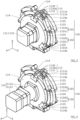
- the support module 11 is provided with several articulated arms 110, each articulated arm 110 comprising the support portion 1100.
- the support portion 1100 can further be moved by a movement of an articulated arm 110.
- each articulated arm 110 is more deployed than in the release configuration.
- each articulated arm 110 can be deployed such that the support portion 1100 is supported on the wall 20 of the duct 2.
- the distal pivot 1103 and the proximal pivot 1104 each allow the relative rotation of the first rod 1101 and the second rod 1102 about an axis parallel to the longitudinal axis of the first frame 10. More particularly, the first rod 1101 and the second rod 1102 each comprise a distal portion 1101b, 1102b and a proximal portion 1101c, 1102c.
- the distal portion 1101b, 1102b and the proximal portion 1101c, 1102c of each of the first rod 1101 and second rod 1102 are articulated in rotation by an intermediate pivot 1105, about an axis parallel to the longitudinal axis of the first frame 10.
- the intermediate pivot 1105 is located between the distal pivot 1103 and the proximal pivot 1104, along each of the first rod 1101 and second rod 1102.
Landscapes
- Engineering & Computer Science (AREA)
- Chemical & Material Sciences (AREA)
- Combustion & Propulsion (AREA)
- General Engineering & Computer Science (AREA)
- Mechanical Engineering (AREA)
- Robotics (AREA)
- Manipulator (AREA)
Claims (13)
- Explorationsroboter (1) für Rohre (2), umfassend ein erstes Gehäuse (10) und ein zweites Gehäuse (10'), wobei das erste Gehäuse (10) und das zweite Gehäuse (10') jeweils ein Lagermodul (11) umfassen, das mit mehreren Gelenkarmen (110) versehen ist, wobei jeder Gelenkarm (110) einen Lagerabschnitt (1100) umfasst, der an einer Wand (20) des Rohrs (2) angebracht werden kann, wobei der Lagerabschnitt (1100) durch eine Bewegung eines Gelenkarms (110) verschiebbar ist, wobei jedes Lagermodul (11) dazu konfiguriert ist, abwechselnd von einer Eingriffskonfiguration des Lagerabschnitts (1100) in eine Freigabekonfiguration des Lagerabschnitts (1100) überzugehen, wobei jeder Gelenkarm (110) in der Eingriffskonfiguration weiter entfaltet wird als in der Freigabekonfiguration,wobei jedes Lagermodul (11) ferner derart konfiguriert, dass die Gelenkarme (110) in einer Ebene senkrecht zu einer Längsachse (x) von mindestens einem des ersten Gehäuses (10) und des zweiten Gehäuses (10') angeordnet sind, und derart, dass die Gelenkarme (110) über eine Drehbewegung über mindestens einen Winkelsektor um eine Achse, die parallel zur Längsachse (x) von mindestens einem des ersten Gehäuses (10) und des zweiten Gehäuses (10') liegt, mindestens teilweise zwischen der Eingriffskonfiguration und der Freigabekonfiguration beweglich sind, wobei jeder Gelenkarm (110) eine erste Stange (1101) und eine zweite Stange (1102) umfasst, wobei die erste Stange (1101) derart konfiguriert ist, dass sie durch mindestens einen distalen Drehzapfen (1103) und einen proximalen Drehzapfen (1104) gelenkig mit der zweiten Stange (1102) in einer Richtung parallel zur Längsachse von mindestens einem des ersten Gehäuses (10) und des zweiten Gehäuses (10') drehverbunden ist,wobei der Roboter dadurch gekennzeichnet ist,dass die erste Stange (1101) und die zweite Stange (1102) jeweils einen distalen Abschnitt (1101b, 1102b) und einen proximalen Abschnitt (1101c, 1102c) umfassen, wobei der distale Abschnitt (1101b, 1102b) und der proximale Abschnitt (1101c, 1102c) durch einen mittleren Drehzapfen (1105) gelenkig in einer Richtung parallel zur Längsachse von mindestens einem des ersten Gehäuses (10) und des zweiten Gehäuses (10`) drehverbunden sind, wobei der mittlere Drehzapfen (1105) sich zwischen dem distalen Drehzapfen (1103) und dem proximalen Drehzapfen (1104) jeweils entlang der ersten Stange (1101) und der zweiten Stange (1102) befindet.
- Roboter (1) nach dem vorhergehenden Anspruch, wobei ein distales Ende (1101a) der ersten Stange (1101) durch den distalen Drehzapfen (1103) gelenkig mit einem distalen Ende (1102a) der zweiten Stange (1102) verbunden ist, wobei das distale Ende (1101a) der ersten Stange (1101) und das distale Ende (1102a) der zweiten Stange (1102) den Lagerabschnitt (1200) jedes Gelenkarms (110) bilden.
- Roboter (1) nach einem der vorhergehenden Ansprüche, wobei das Lagermodul (11) einen Antriebsmechanismus (111) und einen Motorblock (112) umfasst, wobei der Antriebsmechanismus (111) derart konfiguriert ist, dass er durch den Motorblock (112) angetrieben wird und beim abwechselnden Übergehen von der Eingriffskonfiguration in die Freigabekonfiguration die Drehbewegung mindestens eines Teils jedes Gelenkarms (110) induziert.
- Roboter (1) nach dem vorhergehenden Anspruch, wobei der Antriebsmechanismus (111) ein erstes Hohlrad (1110) umfasst, wobei die erste Stange (1101) jedes Gelenkarms (110) derart auf dem ersten Hohlrad (1110) montiert wird, dass sie sich um mindestens einen Winkelsektor relativ zum ersten Hohlrad frei um eine Achse parallel zur Längsachse (x) drehen kann, wobei das erste Hohlrad (1110) ferner derart konfiguriert ist, dass es beim Übergehen von der Freigabekonfiguration in die Eingriffskonfiguration in der ersten Drehrichtung (S1) und beim Übergehen von der Eingriffskonfiguration in die Freigabekonfiguration in der zweiten Richtung (S2) angetrieben wird, wobei die zweite Drehrichtung (S2) der ersten Drehrichtung (S1) entgegengesetzt ist.
- Roboter (1) nach dem vorhergehenden Anspruch, wobei der Antriebsmechanismus (111) ferner ein mechanisches Untersetzungsgetriebe (1112) umfasst, das mindestens derart konfiguriert ist, dass es eine Drehung des ersten Hohlrads (1110) induziert.
- Roboter (1) nach dem vorhergehenden Anspruch, wobei der Motorblock (112) ein Ritzel (1121) umfasst und das Untersetzungsgetriebe (1112) ein erstes Zahnrad (1112a) umfasst, das einerseits mit dem Ritzel (1121) zusammenwirkt, um um eine Drehachse parallel zur Längsachse des Ritzels (1121) drehangetrieben zu werden, und andererseits mit dem ersten Hohlrad (1110).
- Roboter (1) nach einem der Ansprüche 4 bis 6, wobei der Antriebsmechanismus (111) ein zweites Hohlrad (1111) umfasst, wobei die zweite Stange (1102) derart auf dem zweiten Hohlrad (1111) montiert ist, dass sie sich um mindestens einen Winkelsektor relativ zum zweiten Hohlrad (1111) frei um eine Achse parallel zur Längsachse von mindestens einem des ersten Gehäuses (10) und des zweiten Gehäuses (10`) drehen kann, wobei das zweite Hohlrad (1111) derart konfiguriert ist, dass es beim Übergehen von der Freigabekonfiguration in die Eingriffskonfiguration in der zweiten Drehrichtung (S2) und beim Übergehen von der Eingriffskonfiguration in die Freigabekonfiguration in der ersten Richtung (S1) angetrieben wird.
- Roboter (1) nach dem vorhergehenden Anspruch, wobei der Antriebsmechanismus (111) ein mechanisches Untersetzungsgetriebe (1112) umfasst, wobei das Untersetzungsgetriebe (1112) ein erstes Zahnrad (1112a) umfasst, das einerseits derart mit dem Ritzel (1121) zusammenwirkt, dass es um eine Drehachse parallel zur Längsachse des Ritzels (1121) drehangetrieben wird, und andererseits mit dem ersten Hohlrad (1110), wobei das Untersetzungsgetriebe (1112) ferner ein zweites Zahnrad (1112b) umfasst, das einerseits derart mit dem ersten Zahnrad (1112a) zusammenwirkt, dass es um eine Drehachse parallel zur Längsachse des Ritzels (1121) drehangetrieben wird, und andererseits mit dem zweiten Hohlrad (1111).
- Roboter (1) nach einem der Ansprüche 3 bis 8, wobei das Lagermodul (11) mindestens ein Montageelement (113) umfasst, das dazu konfiguriert ist, den Antriebsmechanismus (111) zusammenzuhalten.
- Roboter (1) nach dem vorhergehenden Anspruch, wobei der Antriebsmechanismus (111) ein erstes Hohlrad (1110) und ein zweites Hohlrad (1111) umfasst, wobei das erste Hohlrad (1110) und das zweite Hohlrad (1111) zwischen einer ersten Grundplatte (114) und einer zweiten Grundplatte (114) angeordnet sind, wobei das mindestens eine Montageelement (113) auf der ersten Grundplatte (114) und der zweiten Grundplatte (114) derart montiert ist, dass es den Antriebsmechanismus (111) zusammenhält.
- Roboter (1) nach dem vorhergehenden Anspruch, wobei das mindestens eine Montageelement (113) ein erstes Befestigungselement (1130), das auf der ersten Grundplatte (114) montiert ist, ein zweites Befestigungselement (1130), das auf der zweiten Grundplatte (114) montiert ist, und eine Platte (1131) umfasst, die auf dem ersten Befestigungselement (1130) und dem zweiten Befestigungselement (1130) montiert ist, wobei die Platte (1131) so konfiguriert ist, dass sie nicht in direktem Kontakt mit dem ersten Hohlrad (1110) und dem zweiten Zahnkranz (1111) steht.
- Roboter (1) nach einem der Ansprüche 3 bis 11, wobei der Motorblock (112) einen Schrittmotor (1122) oder einen Getriebeschrittmotor (1122) und ein Codierrad (1123) umfasst, wobei das Codierrad (1123) mit dem Schrittmotor (1122) oder dem Getriebeschrittmotor (1122) zusammenwirkt, um beim abwechselnden Übergehen von der Freigabekonfiguration des Lagerabschnitts (1100) in die Eingriffskonfiguration des Lagerabschnitts (1100) einen Grad der Entfaltung der Gelenkarme (110) zu messen.
- Roboter nach einem der vorhergehenden Ansprüche, wobei jeder distale und proximale Drehzapfen (1103, 1104) eine Gelenkverbindung bildet, die die erste Stange (1101) und die zweite Stange (1102) zusammenfügt, wobei jeder distale und proximale Drehzapfen (1103, 1104) miteinander drehverbunden ist.
Applications Claiming Priority (2)
| Application Number | Priority Date | Filing Date | Title |
|---|---|---|---|
| FR1910179A FR3100857B1 (fr) | 2019-09-16 | 2019-09-16 | Robot d’exploration de conduit comprenant un module de prise d’appui |
| PCT/EP2020/075401 WO2021052869A1 (fr) | 2019-09-16 | 2020-09-10 | Robot d'exploration de conduit comprenant un module de prise d'appui |
Publications (3)
| Publication Number | Publication Date |
|---|---|
| EP4031793A1 EP4031793A1 (de) | 2022-07-27 |
| EP4031793B1 true EP4031793B1 (de) | 2024-12-18 |
| EP4031793C0 EP4031793C0 (de) | 2024-12-18 |
Family
ID=68211119
Family Applications (1)
| Application Number | Title | Priority Date | Filing Date |
|---|---|---|---|
| EP20767839.2A Active EP4031793B1 (de) | 2019-09-16 | 2020-09-10 | Rohrexplorationsroboter mit einem lagermodul |
Country Status (6)
| Country | Link |
|---|---|
| US (1) | US12140261B2 (de) |
| EP (1) | EP4031793B1 (de) |
| CA (1) | CA3150144A1 (de) |
| ES (1) | ES3015009T3 (de) |
| FR (1) | FR3100857B1 (de) |
| WO (1) | WO2021052869A1 (de) |
Families Citing this family (15)
| Publication number | Priority date | Publication date | Assignee | Title |
|---|---|---|---|---|
| CN113090866B (zh) * | 2021-04-21 | 2022-08-23 | 衡昇科技有限公司 | 一种可变径的管道机器人 |
| CN113464543A (zh) * | 2021-06-29 | 2021-10-01 | 西北大学 | 一种径向展开机构 |
| CN114923101B (zh) * | 2022-05-09 | 2023-05-23 | 中国石油大学(华东) | 一种用于对口接管测量切割设备的固定装置 |
| CN114962853B (zh) * | 2022-05-10 | 2023-05-23 | 西南石油大学 | 换挡调节式管道机器人 |
| CN115370868A (zh) * | 2022-07-13 | 2022-11-22 | 常州工学院 | 一种适用于不规则管道的变构机器人 |
| CN115166792A (zh) * | 2022-07-29 | 2022-10-11 | 沈阳航空航天大学 | 一种可变形接触式的管路巡检机器人 |
| CN115727218B (zh) * | 2022-12-07 | 2025-06-27 | 北京北排建设有限公司 | 一种用于封堵大口径排水管道的设备及其使用方法 |
| CN115727219B (zh) * | 2022-12-19 | 2023-05-12 | 杭州四叶智能设备有限公司 | 一种uv光固化灯架 |
| CN115946097B (zh) * | 2022-12-29 | 2023-07-14 | 武汉科技大学 | 一种金属管道质量管外检测机器人 |
| CN116398745B (zh) * | 2023-05-11 | 2025-09-09 | 中山大学 | 一种用于深海管道探索的自适应折展机器人 |
| CN116295442B (zh) * | 2023-05-11 | 2023-10-13 | 国网浙江宁波市鄞州区供电有限公司 | 管道运行设备防跌落控制方法、装置、设备及存储介质 |
| CN117162700A (zh) * | 2023-10-13 | 2023-12-05 | 西北大学 | 可变径的麦克纳姆轮结构及机器人 |
| CN117128392B (zh) * | 2023-10-13 | 2026-03-20 | 西北大学 | 一种管道检测机器人 |
| IT202400002382A1 (it) | 2024-02-05 | 2025-08-05 | Nautilon S R L | Sistema e metodo di mappatura per la creazione di una mappa digitale georeferenziata 1 di almeno un tratto di una rete per il convogliamento di liquidi in pressione, in particolare di reti idriche potabili e non potabili. |
| CN119665031B (zh) * | 2024-11-19 | 2026-03-24 | 广东联塑科技实业有限公司 | 一种贯穿式双管道扩张密封设备 |
Family Cites Families (13)
| Publication number | Priority date | Publication date | Assignee | Title |
|---|---|---|---|---|
| JPH0493188A (ja) * | 1990-08-03 | 1992-03-25 | Toshiba Corp | 配管内点検ロボット |
| EP0484701A1 (de) * | 1990-10-19 | 1992-05-13 | Looper-Robot Systems Co., Ltd | Vorrichtung, die in ein Rohr bewegen kann; Verfahren zum Bewegen der Vorrichtung in ein Rohr und Trägermechanismus |
| KR100285888B1 (ko) * | 1998-07-31 | 2001-04-16 | 장인순 | 관로 원격 검사/보수용 다중공구 |
| US6450104B1 (en) | 2000-04-28 | 2002-09-17 | North Carolina State University | Modular observation crawler and sensing instrument and method for operating same |
| US8292448B2 (en) | 2010-09-24 | 2012-10-23 | Lg Innotek Co., Ltd. | Flat lighting assembly apparatus including flat lighting module |
| US8805579B2 (en) | 2011-02-19 | 2014-08-12 | Richard Arthur Skrinde | Submersible robotically operable vehicle system for infrastructure maintenance and inspection |
| DK2691684T3 (en) * | 2011-03-31 | 2016-08-01 | The Safer Plug Company Ltd | Progress of device |
| KR101255674B1 (ko) * | 2011-11-02 | 2013-04-17 | 연세대학교 산학협력단 | 관 내 이동용 로봇 |
| EP3519724A4 (de) | 2016-09-28 | 2020-10-14 | Redzone Robotics, Inc. | Vorrichtungen, produkte und verfahren zur rohrbildgebung und -inspektion |
| CN107191740A (zh) | 2017-05-26 | 2017-09-22 | 哈尔滨工程大学 | 一种液压驱动定径管道机器人 |
| CN207005570U (zh) | 2017-07-31 | 2018-02-13 | 广州大学 | 一种管道内蠕动式移动机构 |
| CN108223968B (zh) * | 2017-12-01 | 2023-10-20 | 上海大学 | 一种自主式小型管道机器人 |
| CN208417970U (zh) * | 2018-07-24 | 2019-01-22 | 北京市和平街第一中学 | 管道蠕动机器人 |
-
2019
- 2019-09-16 FR FR1910179A patent/FR3100857B1/fr active Active
-
2020
- 2020-09-10 EP EP20767839.2A patent/EP4031793B1/de active Active
- 2020-09-10 ES ES20767839T patent/ES3015009T3/es active Active
- 2020-09-10 US US17/760,574 patent/US12140261B2/en active Active
- 2020-09-10 WO PCT/EP2020/075401 patent/WO2021052869A1/fr not_active Ceased
- 2020-09-10 CA CA3150144A patent/CA3150144A1/fr active Pending
Also Published As
| Publication number | Publication date |
|---|---|
| CA3150144A1 (fr) | 2021-03-25 |
| US12140261B2 (en) | 2024-11-12 |
| FR3100857A1 (fr) | 2021-03-19 |
| US20220341533A1 (en) | 2022-10-27 |
| EP4031793A1 (de) | 2022-07-27 |
| WO2021052869A1 (fr) | 2021-03-25 |
| EP4031793C0 (de) | 2024-12-18 |
| ES3015009T3 (en) | 2025-04-28 |
| FR3100857B1 (fr) | 2021-12-31 |
Similar Documents
| Publication | Publication Date | Title |
|---|---|---|
| WO2021052869A1 (fr) | Robot d'exploration de conduit comprenant un module de prise d'appui | |
| EP4031792B1 (de) | Kanalsuchroboter mit positionierungssystem | |
| EP0378480B1 (de) | Vorrichtung zum Untersuchen der Innenflächen von Rohren | |
| EP3364123B1 (de) | Solar tracker mit kinematischer kupplung | |
| FR3001793A1 (fr) | Installation solaire avec plusieurs systemes de support suiveur en ligne | |
| WO2017215810A1 (fr) | Robot pour la renovation de conduites forcees, muni d'un systeme anti-vrille de deplacement | |
| FR3011080A1 (fr) | Dispositif d'acquisition d'images destine a l'inspection visuelle de la surface interieure d'un pneumatique et procede associe | |
| FR2979840A1 (fr) | Dispositif et procede de nettoyage de panneaux photovoltaiques. | |
| EP0274925B1 (de) | Vorrichtung zur Exploration und/oder Behandlung einer ebenen runden Fläche | |
| CA2760317A1 (en) | Automatic mechanical guide system for one or more welding unit torches with three pivot axes for the torch(es) | |
| FR2771319A1 (fr) | Dispositif de serrage d'un organe tubulaire notamment au moyen de mors mobiles | |
| FR2914203A1 (fr) | Unite de cintrage d'un tube | |
| FR2795804A1 (fr) | Dispositif pour le deplacement d'un organe dans un tube allonge depuis une extremite de ce tube | |
| EP3189266B1 (de) | Anordnung zur einwirkung auf die äussere oberfläche eines rohres und entsprechendes verfahren | |
| FR2701278A1 (fr) | Procédé de curage et dispositif de curage et d'inspection de collecteurs d'égouts. | |
| FR2730005A1 (fr) | Sonde inclinometrique pour la mesure de l'inclinaison d'un puits de forage | |
| EP0660013B1 (de) | Drehantrieb für ein Zahnrad mit grossem Durchmesser | |
| EP4534759A1 (de) | Robotisches mähsystem für den vegetationsbereich eines schienengebundenen gleises, wartungsfahrzeug und verfahren | |
| FR3075380A1 (fr) | Outillage destine au controle non destructif d'une piece plate | |
| FR2829458A1 (fr) | Vehicule a deplacement par reptation propulse conjointement par ondulations longitudinales et laterales | |
| FR3156880A1 (fr) | Robot d’intervention dans une conduite et procédé associé | |
| FR2878951A1 (fr) | Procede et dispositif de centrage d'un rotor dans son stator au sein d'une turbine de production industrielle d'electricite | |
| WO2002093123A1 (fr) | Banc d'essai pour boites de vitesses de vehicule automobile | |
| FR2921008A1 (fr) | Amelioration d'un robot pouvant ecarter ses jambes par rapport a la verticale | |
| FR2964052A1 (fr) | Procede et systeme de detubage, en particulier de condenseurs |
Legal Events
| Date | Code | Title | Description |
|---|---|---|---|
| STAA | Information on the status of an ep patent application or granted ep patent |
Free format text: STATUS: UNKNOWN |
|
| STAA | Information on the status of an ep patent application or granted ep patent |
Free format text: STATUS: THE INTERNATIONAL PUBLICATION HAS BEEN MADE |
|
| PUAI | Public reference made under article 153(3) epc to a published international application that has entered the european phase |
Free format text: ORIGINAL CODE: 0009012 |
|
| STAA | Information on the status of an ep patent application or granted ep patent |
Free format text: STATUS: REQUEST FOR EXAMINATION WAS MADE |
|
| 17P | Request for examination filed |
Effective date: 20220222 |
|
| AK | Designated contracting states |
Kind code of ref document: A1 Designated state(s): AL AT BE BG CH CY CZ DE DK EE ES FI FR GB GR HR HU IE IS IT LI LT LU LV MC MK MT NL NO PL PT RO RS SE SI SK SM TR |
|
| DAV | Request for validation of the european patent (deleted) | ||
| DAX | Request for extension of the european patent (deleted) | ||
| GRAP | Despatch of communication of intention to grant a patent |
Free format text: ORIGINAL CODE: EPIDOSNIGR1 |
|
| STAA | Information on the status of an ep patent application or granted ep patent |
Free format text: STATUS: GRANT OF PATENT IS INTENDED |
|
| INTG | Intention to grant announced |
Effective date: 20240717 |
|
| GRAS | Grant fee paid |
Free format text: ORIGINAL CODE: EPIDOSNIGR3 |
|
| GRAA | (expected) grant |
Free format text: ORIGINAL CODE: 0009210 |
|
| STAA | Information on the status of an ep patent application or granted ep patent |
Free format text: STATUS: THE PATENT HAS BEEN GRANTED |
|
| AK | Designated contracting states |
Kind code of ref document: B1 Designated state(s): AL AT BE BG CH CY CZ DE DK EE ES FI FR GB GR HR HU IE IS IT LI LT LU LV MC MK MT NL NO PL PT RO RS SE SI SK SM TR |
|
| REG | Reference to a national code |
Ref country code: CH Ref legal event code: EP |
|
| REG | Reference to a national code |
Ref country code: DE Ref legal event code: R096 Ref document number: 602020043392 Country of ref document: DE |
|
| REG | Reference to a national code |
Ref country code: IE Ref legal event code: FG4D Free format text: LANGUAGE OF EP DOCUMENT: FRENCH |
|
| U01 | Request for unitary effect filed |
Effective date: 20250116 |
|
| U07 | Unitary effect registered |
Designated state(s): AT BE BG DE DK EE FI FR IT LT LU LV MT NL PT RO SE SI Effective date: 20250122 |
|
| PG25 | Lapsed in a contracting state [announced via postgrant information from national office to epo] |
Ref country code: HR Free format text: LAPSE BECAUSE OF FAILURE TO SUBMIT A TRANSLATION OF THE DESCRIPTION OR TO PAY THE FEE WITHIN THE PRESCRIBED TIME-LIMIT Effective date: 20241218 |
|
| PG25 | Lapsed in a contracting state [announced via postgrant information from national office to epo] |
Ref country code: NO Free format text: LAPSE BECAUSE OF FAILURE TO SUBMIT A TRANSLATION OF THE DESCRIPTION OR TO PAY THE FEE WITHIN THE PRESCRIBED TIME-LIMIT Effective date: 20250318 |
|
| PG25 | Lapsed in a contracting state [announced via postgrant information from national office to epo] |
Ref country code: GR Free format text: LAPSE BECAUSE OF FAILURE TO SUBMIT A TRANSLATION OF THE DESCRIPTION OR TO PAY THE FEE WITHIN THE PRESCRIBED TIME-LIMIT Effective date: 20250319 |
|
| PG25 | Lapsed in a contracting state [announced via postgrant information from national office to epo] |
Ref country code: RS Free format text: LAPSE BECAUSE OF FAILURE TO SUBMIT A TRANSLATION OF THE DESCRIPTION OR TO PAY THE FEE WITHIN THE PRESCRIBED TIME-LIMIT Effective date: 20250318 |
|
| PG25 | Lapsed in a contracting state [announced via postgrant information from national office to epo] |
Ref country code: SM Free format text: LAPSE BECAUSE OF FAILURE TO SUBMIT A TRANSLATION OF THE DESCRIPTION OR TO PAY THE FEE WITHIN THE PRESCRIBED TIME-LIMIT Effective date: 20241218 |
|
| PG25 | Lapsed in a contracting state [announced via postgrant information from national office to epo] |
Ref country code: PL Free format text: LAPSE BECAUSE OF FAILURE TO SUBMIT A TRANSLATION OF THE DESCRIPTION OR TO PAY THE FEE WITHIN THE PRESCRIBED TIME-LIMIT Effective date: 20241218 |
|
| PG25 | Lapsed in a contracting state [announced via postgrant information from national office to epo] |
Ref country code: IS Free format text: LAPSE BECAUSE OF FAILURE TO SUBMIT A TRANSLATION OF THE DESCRIPTION OR TO PAY THE FEE WITHIN THE PRESCRIBED TIME-LIMIT Effective date: 20250418 |
|
| PG25 | Lapsed in a contracting state [announced via postgrant information from national office to epo] |
Ref country code: SK Free format text: LAPSE BECAUSE OF FAILURE TO SUBMIT A TRANSLATION OF THE DESCRIPTION OR TO PAY THE FEE WITHIN THE PRESCRIBED TIME-LIMIT Effective date: 20241218 |
|
| PG25 | Lapsed in a contracting state [announced via postgrant information from national office to epo] |
Ref country code: CZ Free format text: LAPSE BECAUSE OF FAILURE TO SUBMIT A TRANSLATION OF THE DESCRIPTION OR TO PAY THE FEE WITHIN THE PRESCRIBED TIME-LIMIT Effective date: 20241218 |
|
| PGFP | Annual fee paid to national office [announced via postgrant information from national office to epo] |
Ref country code: MC Payment date: 20250905 Year of fee payment: 6 |
|
| PLBE | No opposition filed within time limit |
Free format text: ORIGINAL CODE: 0009261 |
|
| STAA | Information on the status of an ep patent application or granted ep patent |
Free format text: STATUS: NO OPPOSITION FILED WITHIN TIME LIMIT |
|
| REG | Reference to a national code |
Ref country code: CH Ref legal event code: L10 Free format text: ST27 STATUS EVENT CODE: U-0-0-L10-L00 (AS PROVIDED BY THE NATIONAL OFFICE) Effective date: 20251029 |
|
| REG | Reference to a national code |
Ref country code: CH Ref legal event code: U11 Free format text: ST27 STATUS EVENT CODE: U-0-0-U10-U11 (AS PROVIDED BY THE NATIONAL OFFICE) Effective date: 20251031 |
|
| U20 | Renewal fee for the european patent with unitary effect paid |
Year of fee payment: 6 Effective date: 20250926 |
|
| 26N | No opposition filed |
Effective date: 20250919 |
|
| PGFP | Annual fee paid to national office [announced via postgrant information from national office to epo] |
Ref country code: GB Payment date: 20251023 Year of fee payment: 6 |
|
| PGFP | Annual fee paid to national office [announced via postgrant information from national office to epo] |
Ref country code: CH Payment date: 20251031 Year of fee payment: 6 |
|
| PGFP | Annual fee paid to national office [announced via postgrant information from national office to epo] |
Ref country code: ES Payment date: 20251017 Year of fee payment: 6 |