EP4031842B1 - Messgerät zur bestimmung eines dielektrizitätswertes - Google Patents
Messgerät zur bestimmung eines dielektrizitätswertes Download PDFInfo
- Publication number
- EP4031842B1 EP4031842B1 EP20761195.5A EP20761195A EP4031842B1 EP 4031842 B1 EP4031842 B1 EP 4031842B1 EP 20761195 A EP20761195 A EP 20761195A EP 4031842 B1 EP4031842 B1 EP 4031842B1
- Authority
- EP
- European Patent Office
- Prior art keywords
- electrode
- measuring device
- frequency
- frequency signal
- measurement rod
- Prior art date
- Legal status (The legal status is an assumption and is not a legal conclusion. Google has not performed a legal analysis and makes no representation as to the accuracy of the status listed.)
- Active
Links
Images


Classifications
-
- G—PHYSICS
- G01—MEASURING; TESTING
- G01F—MEASURING VOLUME, VOLUME FLOW, MASS FLOW OR LIQUID LEVEL; METERING BY VOLUME
- G01F23/00—Indicating or measuring liquid level or level of fluent solid material, e.g. indicating in terms of volume or indicating by means of an alarm
- G01F23/22—Indicating or measuring liquid level or level of fluent solid material, e.g. indicating in terms of volume or indicating by means of an alarm by measuring physical variables, other than linear dimensions, pressure or weight, dependent on the level to be measured, e.g. by difference of heat transfer of steam or water
- G01F23/28—Indicating or measuring liquid level or level of fluent solid material, e.g. indicating in terms of volume or indicating by means of an alarm by measuring physical variables, other than linear dimensions, pressure or weight, dependent on the level to be measured, e.g. by difference of heat transfer of steam or water by measuring the variations of parameters of electromagnetic or acoustic waves applied directly to the liquid or fluent solid material
- G01F23/284—Electromagnetic waves
- G01F23/2845—Electromagnetic waves for discrete levels
-
- G—PHYSICS
- G01—MEASURING; TESTING
- G01N—INVESTIGATING OR ANALYSING MATERIALS BY DETERMINING THEIR CHEMICAL OR PHYSICAL PROPERTIES
- G01N22/00—Investigating or analysing materials by the use of microwaves or radio waves, i.e. electromagnetic waves with a wavelength of one millimetre or more
-
- G—PHYSICS
- G01—MEASURING; TESTING
- G01R—MEASURING ELECTRIC VARIABLES; MEASURING MAGNETIC VARIABLES
- G01R27/00—Arrangements for measuring resistance, reactance, impedance, or electric characteristics derived therefrom
- G01R27/02—Measuring real or complex resistance, reactance, impedance, or other two-pole characteristics derived therefrom, e.g. time constant
- G01R27/26—Measuring inductance or capacitance; Measuring quality factor, e.g. by using the resonance method; Measuring loss factor; Measuring dielectric constants ; Measuring impedance or related variables
- G01R27/2617—Measuring dielectric properties, e.g. constants
Definitions
- the invention relates to a measuring device for determining a dielectric value of a filling material.
- field devices are often used to record and/or influence various measured variables.
- the measured variable to be determined can be, for example, a fill level, a flow rate, a pressure, the temperature, the pH value, the redox potential, a conductivity or the dielectric value of a medium.
- the field devices each contain suitable sensors or are based on suitable measuring principles. A large number of these field devices are manufactured and sold by Endress + Hauser.
- dielectric value also known as "dielectric constant” or “ relative permittivity”
- dielectric constant also known as "dielectric constant” or " relative permittivity”
- container also includes non-enclosed containers, such as pools, lakes or flowing waters.
- the capacitive measuring principle can be used to determine the dielectric value, especially for liquid products. This makes use of the effect that the capacitance of a capacitor changes proportionally to the dielectric value of the medium that is located between the two electrodes of the capacitor.
- TDR sensors To measure the dielectric value, TDR sensors (TDR is an acronym for " Time Domain Reflectometry” ; in German “Time domain reflectometry”) .
- TDR Time Domain Reflectometry
- the sensor sends a pulse-shaped high-frequency signal with a frequency between 0.1 GHz and 150 GHz along a conductive measuring probe and measures the transit time of the pulse until the reflected high-frequency signal is received. The effect is used that the pulse transit time depends on the dielectric value of the material surrounding the measuring probe.
- the functional principle of TDR sensors is described, for example, in the publication EP 0622 628 A2 TDR sensors are sold in numerous designs, for example by IMKO Mikromodultechnik GmbH.
- Another advantage of TDR sensors is that in addition to the dielectric value, the dielectric loss factor of the material can also potentially be determined.
- the TDR principle also makes it possible to determine the dielectric value of a (liquid) medium inside a container in a quasi-parasitic manner during radar-based level measurement.
- corresponding high-frequency signals are fed into the medium via an electrically conductive measuring probe.
- This combined level and dielectric measurement is described in the published patent application EN 10 2015 117 205 A1
- the measuring probe extends over the entire height of the container due to the principle.
- TDR-based measuring probe Even if only the dielectric value is to be measured, a TDR-based measuring probe may not be able to be designed to be significantly more compact in order to ensure a certain minimum signal runtime and thus achieve sufficiently high measurement accuracy. This means that there is a risk that TDR-based dielectric value measuring devices may be too bulky for certain installation situations.
- the invention is therefore based on the object of providing a compact dielectric value measuring device.
- the term "high frequency” is generally defined as signals between 0.1 GHz and 200 GHz. Depending on the measuring range, however, it is advantageous if the high frequency unit is designed to generate the electrical high frequency signal with a frequency between 0.01 GHz and 10 GHz, in particular between 0.433 GHz and 6 GHz.
- the measuring device is characterized in that the first electrode is wound on a measuring rod that can be brought into contact with the medium.
- the advantage of this is that the measuring probe can be made significantly shorter without limiting the sensitivity of the measuring device. This means that the measuring device can also be used in cramped installation conditions.
- the geometry of the measuring rod is not fixed.
- the measuring rod can, for example, have a circular or rectangular cross-section. It is also conceivable that the measuring rod does not have a straight axis, but rather the axis is curved depending on the location of use.
- the term "unit” is understood to mean in principle any electronic circuit that is suitably designed for the intended purpose. Depending on the requirements, it can therefore be an analog circuit for generating or processing corresponding analog signals. However, it can also be a digital circuit such as an FPGA or a storage medium in conjunction with a program. The program is designed to carry out the corresponding to carry out process steps or to apply the necessary computing operations of the respective unit.
- different electronic units of the level measuring device within the meaning of the invention can potentially also access a common physical memory or be operated using the same physical digital circuit.
- the invention does not specify the measuring principle according to which the dielectric value is determined using the reflected high-frequency signal.
- the high-frequency unit must be designed to generate the high-frequency signal in a corresponding pulse shape.
- the measuring probe can include a second electrode within the measuring rod as a ground potential with respect to the high-frequency signal.
- the second electrode can, for example, have the same geometry as the measuring rod, but with correspondingly smaller dimensions, for example rod-shaped with a round cross-section.
- the first electrode In order for the electromagnetic near field of the high frequency signal to penetrate the medium with minimal loss, the first electrode must be electrically insulated from the measuring rod.
- the first electrode can be designed with an appropriately insulating sheath.
- the measuring rod can also be made of an electrically non-conductive material. To amplify the electromagnetic field of the high frequency signal in the medium, it is advantageous if the insulating material of the measuring rod has a relative dielectric constant of between 6 and 40.
- the measuring rod according to the invention can be provided with an electrically non-conductive coating.
- the electrically insulating coating can consist of glass, PTFE, ABS or ceramic, for example.
- the first electrode along the measuring rod has a winding density of at least 2 windings per wavelength corresponding to the frequency of the high-frequency signal.
- the measuring probe of the measuring device can be extended in such a way that a third electrode is wound onto the measuring rod, approximately congruent with the first electrode.
- the third electrode is arranged within the first electrode in relation to the measuring rod. If the high-frequency unit controls the third electrode with the first high-frequency signal in such a way that the phase positions of the high-frequency signal at the first electrode and the third electrode are approximately the same, this offers the advantage that the electromagnetic near field of the high-frequency signal along the first electrode in the medium is thereby strengthened, thereby increasing the sensitivity of the dielectric value measurement.
- This effect can be used in particular if the third electrode has a larger cross-sectional area than the first electrode.
- the cross-sectional area should be at least 10% larger, but a cross-sectional area up to 400% larger is also conceivable.
- An elongated cross-section is also advantageous in this context.
- Fig.1 a schematic arrangement of the measuring device 1 on a container 3 with a medium 2 is shown:
- the measuring device 1 is arranged on the side of a connection of the container 2, e.g. a flange connection.
- the measuring device 1 is attached approximately in a form-fitting manner to the inner wall of the container.
- the medium 2 can be liquids such as drinks, paints, cement or fuels such as liquid gases or mineral oils.
- the measuring device 1 can be connected to a higher-level unit 4, such as a process control system.
- a higher-level unit 4 such as a process control system.
- PROFIBUS "HART”, “Wireless HART” or “Ethernet” can be implemented as an interface.
- the dielectric value can be transmitted via this as an absolute value or as a complex value with a real part and an imaginary part. However, other information about the general operating status of the measuring device 1 can also be communicated.
- the measuring device 1 comprises a measuring probe 11 which, after installation, extends into the interior of the container 3. As a result, the measuring probe 11 is in contact with the medium 2 at a corresponding minimum fill level of the medium 2, so that the measuring device 1 can determine the dielectric value of the medium 2 via the measuring probe 11.
- the functionality of the measuring device 1 is based on a measuring probe 11, into which a high-frequency signal s HF is impressed, so that the electromagnetic near field of the high-frequency signal s HF penetrates the medium 2.
- the measuring probe 11 comprises a first, electrically conductive electrode 111, into which a high-frequency unit of the measuring device 1 can couple the high-frequency signal s HF .
- the dielectric value can be determined by the high-frequency unit.
- the frequency f HF of the high-frequency signal s HF is dependent on the specific type of Medium 2 or the specific value range of the dielectric value to be measured. For media 2, which have a high water content, a frequency f HF between 0.433 GHz and 6 GHz is recommended.
- measuring principle is used to determine the dielectric value based on the reflected signal r HF . This is because, depending on the design, the dielectric value can influence the propagation time, the amplitude attenuation and the phase shift to the transmitted high-frequency signal s HF .
- the FMCW method ( “Frequency Modulated Continuous Wave ”) or a variant of the TDR method ( “Time Domain Reflectometry”) can be implemented.
- the high-frequency unit for generating the high-frequency signal s HF can accordingly comprise a "phase locked loop” (known in English as a “phase locked loop, PLL” ).
- PLL phase locked loop
- This is based on a controllable, electrical high-frequency oscillator (standardly implemented as a VCO) that generates the electrical high-frequency signal s HF .
- the frequency of the high-frequency signal s HF is controlled by feedback and thus stabilized against fluctuations in the ambient temperature on the one hand; on the other hand, the sawtooth-shaped frequency change of the high-frequency signal s HF , which is typical for FMCW, is set via the feedback:
- the feedback is implemented by branching off a control signal from the high-frequency signal s HF of the high-frequency oscillator and feeding it to a phase comparator.
- the phase comparator in turn compares the current phase shift of the control signal s c to a frequency-constant reference signal.
- the reference signal has a precisely presettable reference frequency with negligible temperature drift.
- the transit time and thus the dielectric value can be adjusted by the high frequency unit in the case of FMCW, for example, by mixing the emitted high frequency signal s HF with the signal r HF reflected at the end of the first electrode 111, since the frequency of the mixed signal changes linearly with the propagation time.
- the high-frequency unit for cyclically generating the high-frequency signal s HF in pulse form can, for example, comprise a correspondingly cyclically controlled oscillator, for example again a voltage-controlled oscillator or just a quartz oscillator.
- the high-frequency unit can process the reflected signal r HF according to the pulse transit time method by subsampling. The subsampling stretches the reflected signal r HF in the time axis so that the signal maximum, which corresponds to the signal transit time, can be determined in a simplified circuit manner.
- the first electrode 111 must have a defined minimum length so that the high-frequency unit can determine the signal propagation time of the (reflected) high-frequency signal s HF , r HF , or the propagation time change depending on different media 2 with different dielectric values with sufficient resolution. In practice, this means that the measuring probe 11 must have a corresponding minimum length. However, depending on the installation situation or container size, this can make the measuring device 1 too bulky for the respective application.
- the measuring device 1 can be designed to be significantly more compact: As shown, the first electrode 111 is wound onto a measuring rod 110, whereby the measuring rod 110 is electrically insulated from the first electrode 111.
- the first electrode 111 can be designed as a sheathed Cu or Au cable, for example, or the measuring rod 110 can also be made of an electrically non-conductive material.
- the minimum winding density # min corresponds to approximately 20 windings per meter.
- the measuring rod 110 has a straight axis and a circular cross-section.
- the cross-sectional shape is not strictly prescribed within the scope of the invention and can also be rectangular, for example.
- the axis of the measuring rod 110 can also be curved if the location of use requires it.
- the measuring electrode 11 As ground potential against the (reflected) high frequency signal s HF , r HF the measuring electrode 11 comprises Fig.2
- a rod-shaped second electrode 112 with a round cross section wherein the second electrode 112 is in turn electrically insulated from the measuring rod 110.
- the second electrode 112 is designed to be long enough to extend at least over that area of the measuring rod 110 in which the first electrode 111 is wound onto the measuring rod 110.
- an electrically insulating coating 113 is applied to the measuring rod 110 or around the first electrode 111.
- the coating 113 primarily serves to mechanically or chemically protect the first electrode 111 from external influences. So that the dielectric value of the medium 2 to be examined still has sufficient influence on the electromagnetic field of the high-frequency signal s HF along the first electrode 111, it is advantageous if the coating 113 has a smaller dielectric constant than the measuring rod 1110, which is also electrically insulating.
- the electrically insulating coating 113 can be made, for example, from a material such as glass, PTFE, ABS or a ceramic, which has a correspondingly smaller relative dielectric constant than the measuring rod 110.
- Fig.3 a cross-sectional view of the measuring probe 11 according to the invention is shown: In this view, an extended embodiment is shown in which a third electrode 114 is wound onto the measuring rod 110 approximately congruent with the first electrode 111. The third electrode 114 is arranged within the first electrode 111 in relation to the measuring rod 110.
- both the first electrode 111 and the third electrode 114 have an elongated cross-section in relation to the cross-section of the measuring rod 10.
- the length and thus the cross-sectional area of the third electrode 114 are approximately 150% larger than the cross-sectional area of the first electrode 111.
- This design variant of the measuring probe 11 makes it possible to impress the electromagnetic field of the high-frequency signal s HF along the first electrode 111 with increased intensity into the medium 2 to be examined. This in turn can increase the sensitivity of the measurement.
- the prerequisite for this is that the high-frequency unit of the measuring device 1 also impresses the high-frequency signal s HF on the third electrode 114, approximately in phase with the first electrode 111.
- the third electrode 114 can therefore potentially further reduce the size of the measuring probe 11. without reducing the sensitivity.
- the sensitivity, or the extent of the measuring range around the measuring probe 11, can in turn be variably adjusted via the signal strength with which the high-frequency signal s HF is impressed into the third electrode 114.
Landscapes
- Physics & Mathematics (AREA)
- General Physics & Mathematics (AREA)
- Electromagnetism (AREA)
- Biochemistry (AREA)
- Chemical & Material Sciences (AREA)
- Analytical Chemistry (AREA)
- Life Sciences & Earth Sciences (AREA)
- General Health & Medical Sciences (AREA)
- Health & Medical Sciences (AREA)
- Immunology (AREA)
- Pathology (AREA)
- Thermal Sciences (AREA)
- Fluid Mechanics (AREA)
- Measurement Of Resistance Or Impedance (AREA)
- Investigating Or Analyzing Materials By The Use Of Electric Means (AREA)
Description
- Die Erfindung betrifft ein Messgerät zur Bestimmung eines Dielektrizitätswertes eines Füllgutes.
- In der Automatisierungstechnik, insbesondere in der Prozessautomatisierungstechnik, werden vielfach Feldgeräte eingesetzt, die zur Erfassung und/oder zur Beeinflussung verschiedener Messgrößen dienen. Bei der zu bestimmenden Messgröße kann es sich beispielsweise um einen Füllstand, einen Durchfluss, einen Druck, die Temperatur, der pH-Wert, das Redoxpotential, eine Leitfähigkeit oder der Dielektrizitätswert eines Mediums handeln. Zur Erfassung der entsprechenden Messwerte umfassen die Feldgeräte jeweils geeignete Sensoren bzw. basieren auf geeigneten Messprinzipien. Eine Vielzahl dieser Feldgeräte wird von der Firma Endress + Hauser hergestellt und vertrieben.
- Die Bestimmung des Dielektrizitätswertes (auch bekannt als "Dielektrizitätskonstante" oder "Relative Permittivität") von Füllgütern in Behältern ist sowohl bei Feststoffen, als auch bei flüssigen und gasförmigen Füllgütern, wie beispielsweise Treibstoffen, Abwässern, Gasen oder Chemikalien von großem Interesse, da dieser Wert einen zuverlässigen Indikator für Verunreinigungen, den Feuchtegehalt oder die Stoffzusammensetzung darstellen. Unter dem Begriff "Behälter" werden im Rahmen der Erfindung auch nicht-abgeschlossene Behältnisse, wie beispielsweise Becken, Seen oder fließende Gewässer verstanden.
- Zur Bestimmung des Dielektrizitätswertes kann nach dem Stand der Technik vor allem bei flüssigen Füllgütern auf das kapazitive Messprinzip zurückgegriffen werden. Dabei wird der Effekt genutzt, dass sich die Kapazität eines Kondensators proportional mit dem Dielektrizitätswert desjenigen Mediums, das sich zwischen den zwei Elektroden des Kondensators befindet, ändert.
- Zur Messung des Dielektrizitätswertes werden außerdem TDR-Sensoren (TDR ist ein Akronym für "Time Domain Reflectometry"; zu Deutsch "Zeitbereichsreflektometrie") eingesetzt. Bei diesem Messprinzip sendet der Sensor ein pulsförmiges Hochfrequenz-Signal mit einer Frequenz zwischen 0,1 GHz und 150 GHz entlang einer leitfähigen Mess-Sonde aus und misst die Laufzeit des Pulses bis zum Empfang des reflektierten Hochfrequenz-Signals. Dabei wird der Effekt genutzt, dass die Pulslaufzeit abhängig vom Dielektrizitätswert desjenigen Stoffes ist, der die Mess-Sonde umgibt. Beschrieben ist das Funktionsprinzip von TDR-Sensoren beispielsweise in der Veröffentlichungsschrift
EP 0622 628 A2 . TDR-Sensoren werden in zahlreichen Ausführungsformen beispielsweise von der Firma IMKO Mikromodultechnik GmbH vertrieben. Vorteilhaft an TDR-Sensoren ist außerdem, dass neben dem Dielektrizitätswert potentiell auch der dielektrische Verlustfaktor des Stoffes bestimmt werden kann. - Darüber hinaus ist es mittels des TDR-Prinzips auch möglich, den Dielektrizitätswert eines (flüssigen) Mediums in einem Behälter-Inneren quasi parasitär bei dessen Radar-basierter Füllstandsmessung mitzubestimmen. Auch hier werden entsprechende Hochfrequenz-Signale über eine elektrisch leitfähige Mess-Sonde in das Medium geführt werden. Beschrieben ist diese kombinierte Füllstands- und Dielektrizitäts-Messung in der Offenlegungsschrift
DE 10 2015 117 205 A1 . Bei TDR-basierter Füllstandsmessung erstreckt sich die Mess-Sonde Prinzip-bedingt also über die gesamte Behälter-Höhe. - Auch wenn lediglich der Dielektrizitätswert zu messen ist, kann die eine TDR-basierte Mess-Sonde gegebenenfalls nicht wesentlich kompakter ausgelegt werden, damit eine gewisse Signal-Mindestlaufzeit gewährt wird und dadurch eine hinreichend große Messgenauigkeit erreicht wird. Hierdurch besteht die Gefahr, dass TDR-basierte Dielektrizitätswert-Messgeräte im Zweifelsfall zu sperrig für gewisse Einbausituationen sind.
- Der Erfindung liegt daher die Aufgabe zugrunde, ein kompakt auslegbares Dielektrizitätswert-Messgerät bereitzustellen.
- Die Erfindung löst diese Aufgabe durch ein Messgerät zur Bestimmung des Dielektrizitätswertes eines Mediums, das folgende Komponenten umfasst:
- Eine Mess-Sonde mit
- ∘ einem Mess-Stab, der in Kontakt mit dem Medium bringbar ist,
- o zumindest einer ersten elektrisch leitfähigen Elektrode, die auf dem Mess-Stab aufgewickelt ist,
- o einer zweiten Elektrode,
- eine Hochfrequenz-Einheit, die ausgelegt ist, ein Hochfrequenz-Signal zumindest in die erste Elektrode (111) einzukoppeln und anhand eines entsprechenden Reflexionssignals den Dielektrizitätswert des Mediums zu bestimmen, wobei die zweite Elektrode als Masse-Potential für das Hochfrequenz-Signal bzw. das Reflexionssignal dient, dass sich die zweite Elektrode innerhalb des Mess-Stabs stabförmig über zumindest denjenigen Bereich des Mess-Stabs erstreckt, in dem die erste Elektrode auf dem Mess-Stab aufgewickelt ist.
- Dabei definiert sich der Begriff "Hochfrequenz" im Rahmen der Erfindung allgemein auf Signale zwischen 0,1 GHz bis hin zu 200 GHz. Je nach Messbereich ist es jedoch vorteilhaft, wenn die Hochfrequenz-Einheit ausgelegt ist, das elektrische Hochfrequenz-Signal mit einer Frequenz zwischen 0,01 GHz und 10 GHz, insbesondere zwischen 0,433 GHz und 6 GHz zu erzeugen.
- Erfindungsgemäß zeichnet sich das Messgerät dadurch aus, dass die erste Elektrode auf einem Mess-Stab, der in Kontakt mit dem Medium bringbar ist, aufgewickelt ist. Vorteilhaft hieran ist, dass dadurch die Mess-Sonde deutlich kürzer ausgelegt werden kann, ohne dass die Sensitivität des Messgerätes eingeschränkt wird. Hierdurch kann das Messgerät auch bei beengten Einbauverhältnissen eingesetzt werden. Die Geometrie des Mess-Stabes ist hierbei nicht fest vorgegeben. Der Mess-Stab kann beispielsweise einen kreisförmigen oder einen rechteckigen Querschnitt aufweisen. Denkbar ist es auch, dass der Mess-Stab keine geradlinige Achse aufweist, sondern die Achse je nach Einsatzort entsprechend gekrümmt ist.
- Unter dem Begriff "Einheit" wird im Rahmen der Erfindung prinzipiell jede elektronische Schaltung verstanden, die für den angedachten Einsatzzweck geeignet ausgelegt ist. Es kann sich also je nach Anforderung um eine Analogschaltung zur Erzeugung bzw. Verarbeitung entsprechender analoger Signale handeln. Es kann sich jedoch auch um eine Digitalschaltung wie einem FPGA oder einen Speichermedium in Zusammenwirken mit einem Programm handeln. Dabei ist das Programm ausgelegt, die entsprechenden Verfahrensschritte durchzuführen bzw. die notwendigen Rechenoperationen der jeweiligen Einheit anzuwenden. In diesem Kontext können verschiedene elektronische Einheiten des Füllstandsmessgerätes im Sinne der Erfindung potentiell auch auf einen gemeinsamen physikalischen Speicher zurückgreifen bzw. mittels derselben physikalischen Digitalschaltung betrieben werden.
- Prinzipiell ist es im Rahmen der Erfindung nicht fest vorgegeben, gemäß welchem Messprinzip anhand des reflektierten Hochfrequenz-Signals der Dielektrizitätswert ermittelt wird. Es bietet sich jedoch insbesondere an, den Dielektrizitätswert mittels einem der TDR-Messprinzipien zu ermitteln. In diesen Fällen ist die Hochfrequenz-Einheit auszulegen, um das Hochfrequenz-Signal entsprechend pulsförmig zu erzeugen. Als Masse-Potential gegenüber dem Hochfrequenz-Signal kann die Mess-Sonde innerhalb des Mess-Stabs eine zweite Elektrode umfassen. Dabei kann die zweite Elektrode beispielsweise dieselbe Geometrie wie der Mess-Stab, jedoch mit entsprechend verkleinerten Abmessungen, aufweisen, also beispielsweise stabförmig mit rundem Querschnitt.
- Damit das elektromagnetische Nah-Feld des Hochfrequenz-Signals verlustarm in das Medium eindringen kann, muss die erste Elektrode elektrisch vom Mess-Stab isoliert sein. Hierzu kann beispielsweise die erste Elektrode mit einer entsprechend isolierenden Ummantelung ausgelegt sein. Der Mess-Stab kann hierzu jedoch auch aus einem elektrisch nicht leitfähigen Material gefertigt werden. Zur Verstärkung des elektromagnetischen Feldes des Hochfrequenz-Signals im Medium ist es hierbei vorteilhaft, wenn das isolierende Material des Mess-Stabes ein relative Dielektrizitätszahl von zwischen 6 und 40 aufweist.
- Zum Schutz des Mess-Stabes bzw. der ersten Elektrode vor Umwelteinflüssen, wie abrasiven Medien, kann der erfindungsgemäße Mess-Stab mit einer elektrisch nicht leitfähigen Beschichtung versehen werden. Sofern der Mess-Stab aus einem isolierenden Material gefertigt ist, bietet es sich in diesem Fall an, dass die elektrisch isolierende Beschichtung eine kleinere Dielektrizitätszahl als der Mess-Stab aufweist, so dass sich vom Inneren der Mess-Sonde nach außen quasi ein Gradient der Dielektrizitätszahl einstellt. Hierdurch wird wiederum das Eindringen des elektromagnetischen Feldes des Hochfrequenz-Signals in das Medium verstärkt. Dementsprechend kann die Beschichtung beispielsweise aus einem Glas, PTFE, ABS oder einer Keramik bestehen.
- Da die Sensitivität der Dielektrizitätswert-Messung potentiell umso höher ist, je höher die Wicklungsdichte der ersten Elektrode um den Mess-Stab herum ist, ist es vorteilhaft, wenn die erste Elektrode entlang des Mess-Stabs eine Wicklungsdichte von mindestens 2 Wicklungen pro derjenigen Wellenlänge aufweist, die der Frequenz des Hochfrequenz-Signals entspricht.
- Die Mess-Sonde des erfindungsgemäßen Messgerätes kann in solch einer Form erweitert werden, dass in etwa deckungsgleich zur ersten Elektrode auf dem Mess-Stab eine dritte Elektrode aufgewickelt ist. Dabei ist die dritte Elektrode in Bezug zum Mess-Stab innerhalb der ersten Elektrode angeordnet. Sofern die Hochfrequenz-Einheit die dritte Elektrode derart mit dem ersten Hochfrequenz-Signal ansteuert, dass die Phasenlagen des Hochfrequenz-Signals an der ersten Elektrode und der dritten Elektrode in etwa gleich sind, bietet dies den Vorteil, dass hierdurch das elektromagnetische Nahfeld des Hochfrequenz-Signals entlang der ersten Elektrode im Medium verstärkt wird und dadurch die Sensitivität der Dielektrizitätswert-Messung erhöht wird. Genutzt werden kann dieser Effekt insbesondere, wenn die dritte Elektrode eine größere Querschnittsfläche als die erste Elektrode aufweist. In diesem Zusammenhang sollte die Querschnittsfläche mindestens um 10 % größer sein, denkbar ist jedoch auch eine um bis zu 400 % größere Querschnittsfläche. Vorteilhaft ist in diesem Zusammenhang ebenfalls ein länglicher Querschnitt.
- Anhand der nachfolgenden Figuren wird die Erfindung näher erläutert. Es zeigt:
-
Fig. 1 : Ein erfindungsgemäßes Messgerät zur Dielektrizitätswert-Messung eines Mediums in einem Behälter, -
Fig. 2 : eine Mess-Sonde des erfindungsgemäßen Messgerätes, und -
Fig. 3 : eine Querschnittsansicht der erfindungsgemäßen Mess-Sonde. - Zum allgemeinen Verständnis des erfindungsgemäßen Dielektrizitätswert-Messgerätes 1 ist in
Fig. 1 eine schematische Anordnung des Messgerätes 1 an einem Behälter 3 mit einem Medium 2 gezeigt: Zur Bestimmung des Dielektrizitätswertes des Mediums 2 ist das Messgerät 1 seitlich an einem Anschluss des Behälters 2, bspw. einem Flanschanschluss angeordnet. Hierzu ist das Messgerät 1 in etwa formschlüssig zur Behälter-Innenwand angebracht. Bei dem Medium 2 kann es sich um Flüssigkeiten wie Getränke, Lacke, Zement oder Treibstoffe, wie Flüssiggase oder Mineralöle handeln. Denkbar ist jedoch auch die Verwendung des Messgerätes 1 bei Schüttgutförmigen Medien 2, wie bspw. Getreide. - Das Messgerät 1 kann mit einer übergeordneten Einheit 4 wie zum Beispiel einem Prozessleitsystem verbunden sein. Als Schnittstelle kann etwa "PROFIBUS", "HART", "Wireless HART" oder "Ethernet" implementiert sein. Hierüber kann der Dielektrizitätswert als Betrag, oder komplexwertig mit Realteil und Imaginärteil übermittelt werden. Es können aber auch anderweitige Informationen über den allgemeinen Betriebszustand des Messgerätes 1 kommuniziert werden.
- Wie in
Fig. 1 schematisch dargestellt ist, umfasst das erfindungsgemäße Messgerät 1 eine Mess-Sonde 11, die sich nach der Installation in das Innere des Behälters 3 erstreckt. Hierdurch ist die Mess-Sonde 11 bei entsprechendem Mindest-Füllstand des Mediums 2 in Kontakt mit dem Medium 2, so dass das Messgerät 1 über die Mess-Sonde 11 den Dielektrizitätswert des Mediums 2 ermitteln kann. - Grundlegend basiert die Funktionsweise des Messgerätes 1 auf einer Mess-Sonde 11, in die ein Hochfrequenz-Signal sHF eingeprägt wird, so dass das elektromagnetische Nah-Feldes des Hochfrequenz-Signals sHF in das Medium 2 eindringt. Hierzu umfasst die Mess-Sonde 11 eine erste, elektrisch leitfähige Elektrode 111, in welche eine Hochfrequenz-Einheit des Messgerätes 1 das Hochfrequenz-Signal sHF einkoppeln kann. Anhand eines am Ende der ersten Elektrode 111 entsprechend reflektierten Signals rHF kann der Dielektrizitätswert durch die Hochfrequenz-Einheit bestimmt werden. Die Frequenz fHF des Hochfrequenz-Signals sHF ist auf den konkreten Typ an Medium 2 bzw. den konkreten Wertebereich des zu messenden Dielektrizitätswertes anzupassen. Für Medien 2, die einen hohen Wasseranteil aufweisen, bietet sich dementsprechend eine Frequenz fHF zwischen 0,433 GHz und 6 GHz an.
- Prinzipiell ist es im Rahmen der Erfindung nicht fest vorgegeben, gemäß welchem Messprinzip anhand des reflektierten Signals rHF der Dielektrizitätswert ermittelt wird. Denn der Dielektrizitätswert kann je nach Auslegung sowohl die Laufzeit, die Amplituden-Dämpfung als auch die Phasenverschiebung zum ausgesendeten Hochfrequenz-Signal sHF beeinflussen.
- Im Falle der Signallaufzeit kann analog zum geführten Radar beispielsweise das FMCW-Verfahren ("Frequency Modulated Continuos Wave") oder eine Variante des TDR-Verfahrens ("Time Domain Reflectometry") implementieren.
- Im Fall von FMCW kann die Hochfrequenz-Einheit zur Erzeugung des Hochfrequenz-Signals sHF dementsprechend einen "Phasenregelkreis" (im englischen als "Phase Locked Loop, PLL" bekannt) umfassen. Dieser basiert auf einem steuerbaren, elektrischen Hochfrequenz-Oszillator (standartmäßig als VCO realisiert), der das elektrische Hochfrequenz-Signal sHF erzeugt. Die Frequenz des Hochfrequenz-Signals sHF wird hierbei per Rückkopplung geregelt und somit einerseits gegenüber Schwankungen der Umgebungstemperatur stabilisiert; Andererseits wird über die Rückkopplung die bei FMCW typische, sägezahnförmige Frequenzänderung des Hochfrequenz-Signals sHF eingestellt: Die Rückkopplung wird realisiert, indem aus dem Hochfrequenz-Signal sHF des Hochfrequenz-Oszillators ein Regelsignal abgezweigt und einem Phasenkomparator zugeführt wird. Der Phasenkomparator vergleicht wiederum die momentane Phasenverschiebung des Regelsignals sc zu einem frequenzkonstanten Referenzsignal. Das Referenzsignal weist hierbei eine exakt voreinstellbare Referenzfrequenz mit vernachlässigbarem Temperaturdrift auf.
- Die Laufzeit und somit den Dielektrizitätswert kann die Hochfrequenz-Einheit im Falle von FMCW beispielsweise durch Mischen des ausgesendeten Hochfrequenz-Signals sHF mit dem am Ende der ersten Elektrode 111 reflektierten Signal rHF bestimmen, da sich die Frequenz des gemischten Signals linear mit der Laufzeit ändert.
- Bei Implementierung des TDR-Verfahrens kann die Hochfrequenz-Einheit zur zyklisch pulsförmigen Erzeugung des Hochfrequenz-Signals sHF beispielsweise einen entsprechend zyklisch angesteuerten Oszillator, beispielsweise wiederum einen spannungsgesteuerten Oszillator oder lediglich einen Quarzoszillator, umfassen. Zur Bestimmung der Laufzeit bzw. des Dielektrizitätswertes kann die Hochfrequenz-Einheit das reflektierte Signal rHF gemäß dem Puls-Laufzeit-Verfahren durch Unterabtastung verarbeiten. Durch die Unterabtastung wird das reflektierte Signal rHF in der Zeitachse gedehnt, so dass das Signal-Maximum, welches zur Signal-Laufzeit korrespondiert, schaltungstechnisch vereinfacht ermittelt werden kann.
- Trotz einer etwaigen Zeitdehnung muss die erste Elektrode 111 eine definierte Mindestlänge aufweisen, damit die Hochfrequenz-Einheit die Signallaufzeit des (reflektierten) Hochfrequenz-Signals sHF, rHF, bzw. die Laufzeit-Änderung in Abhängigkeit verschiedener Medien 2 mit verschiedenen Dielektrizitätswerten mit hinreichender Auflösung bestimmen kann. In der Praxis führt dies dazu, dass die Mess-Sonde 11 eine entsprechende MindestLänge aufweisen muss. Hierdurch kann das Messgerät 1 jedoch je nach Einbausituation oder Behältergröße zu sperrig für die jeweilige Anwendung ausfallen.
- Auf Basis der erfindungsgemäßen Mess-Sonde 11, wie sie in
Fig. 2 gezeigt ist, kann das Messgerät 1 deutlich kompakter ausgelegt werden: Wie dargestellt, ist die erste Elektrode 111 hierzu auf einem Mess-Stab 110 aufgewickelt, wobei der Mess-Stab 110 elektrisch von der ersten Elektrode 111 isoliert ist. Zwecks Isolation kann die erste Elektrode 111 beispielsweise als ummanteltes Cu- oder Au-Kabel ausgelegt sein, oder der Mess-Stab 110 kann hierzu auch aus einem elektrisch nicht leitfähigen Material gefertigt sein. - Je höher die Wicklungsdichte der ersten Elektrode 111 um den Mess-Stab 110 herum ist, desto höher ist potentiell auch die Sensitivität der Dielektrizitätswert-Messung. Mindestens ist die Wicklungsdichte #min jedoch so auszulegen, dass die erste Elektrode 111 entlang des Mess-Stabs 110 eine Wicklungsdichte #min von mindestens 2 Wicklungen pro derjenigen Wellenlänge λHF aufweist, die der Frequenz fHF des Hochfrequenz-Signals sHF entspricht, gemäß:
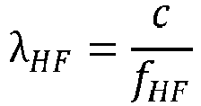

- Bei einer Frequenz fHF des Hochfrequenz-Signals sHF von 1 GHz entspricht die Mindest-Wicklungsdichte #min gemäß dieser Formel somit ungefähr 20 Wicklungen pro Meter.
- Bei der in
Fig. 2 gezeigten Ausführungs-Variante weist der Mess-Stab 110 eine gerade Achse und einen kreisförmigen Querschnitt auf. Allgemein ist die Querschnittsform im Rahmen der Erfindung jedoch nicht fest vorgeschrieben und kann beispielsweise auch rechteckig sein. Auch die Achse des Mess-Stabs 110 kann im Gegensatz zu der gezeigten Ausführungsvariante gekrümmt sein, sofern es der Einsatzort erfordern sollte. - Als Masse-Potential gegenüber dem (reflektierten) Hochfrequenz-Signal sHF, rHF umfasst die Mess-Elektrode 11 bei der in
Fig. 2 gezeigten Ausführungsvariante bezogen auf den Querschnitt im Kreismittelpunkt des Mess-Stabes 110 eine stabförmige zweite Elektrode 112 mit ebenfalls rundem Querschnitt, wobei die zweite Elektrode 112 wiederum elektrisch vom Mess-Stab 110 isoliert ist. Dabei ist die zweite Elektrode 112 lang genug ausgelegt, um sich zumindest über denjenigen Bereich des Mess-Stabs 110 zu erstrecken, in dem die erste Elektrode 111 auf dem Mess-Stab 110 aufgewickelt ist. - Bei der in
Fig. 2 dargestellten Ausführungsvariante der Mess-Sonde 11 ist auf dem Mess-Stab 110 bzw. um die erste Elektrode 111 herum eine elektrisch isolierende Beschichtung 113 aufgebracht. Die Beschichtung 113 dient dabei primär dem mechanischen bzw. chemischen Schutz der ersten Elektrode 111 vor äußeren Einflüssen. Damit der Dielektrizitätswert des zu untersuchenden Mediums 2 dennoch hinreichend Einfluss auf das elektromagnetische Feld des Hochfrequenz-Signals sHF entlang der ersten Elektrode 111 hat, ist es vorteilhaft, wenn die Beschichtung 113 eine kleinere Dielektrizitätszahl als der elektrisch ebenfalls isolierende Mess-Stab 1110 aufweist. Sofern der Mess-Stab 110 also aus einem Material mit einer relativen Dielektrizitätszahl zwischen 6 und 40 F*m-1 aufgebaut ist, kann die elektrisch isolierende Beschichtung 113 beispielsweise aus einem Material wie Glas, PTFE, ABS oder einer Keramik gefertigt werden, das eine entsprechend kleinere relative Dielektrizitätszahl als der Mess-Stab 110 aufweist. - In
Fig. 3 ist eine Querschnittsansicht der erfindungsgemäßen Mess-Sonde 11 dargestellt: In dieser Ansicht ist eine erweiterte Ausführungsvariante dargestellt, bei der in etwa deckungsgleich zur ersten Elektrode 111 auf dem Mess-Stab 110 eine dritte Elektrode 114 aufgewickelt ist. Dabei ist die dritte Elektrode 114 in Bezug zum Mess-Stab 110 innerhalb der ersten Elektrode 111 angeordnet. - Sowohl die erste Elektrode 111 als auch die dritte Elektrode 114 weisen in der gezeigten Darstellung in Bezug zum Querschnitt des Mess-Stabes 10 einen länglichen Querschnitt auf. Dabei sind die Länge und somit die Querschnittsfläche der dritten Elektrode 114 um ca. 150 % größer als die Querschnittsfläche der ersten Elektrode 111. Diese Ausführungsvariante der Mess-Sonde 11 ermöglicht es, das elektromagnetische Feld des Hochfrequenz-Signals sHF entlang der ersten Elektrode 111 mit erhöhter Intensität in das zu untersuchende Medium 2 einzuprägen. Hierdurch kann wiederum die Sensitivität der Messung erhöht werden. Voraussetzung ist hierfür, dass die Hochfrequenz-Einheit des Messgerätes 1 auch an der dritten Elektrode 114 das Hochfrequenz-Signal sHF einprägt, und zwar ungefähr phasengleich zur ersten Elektrode 111. Durch die dritte Elektrode 114 kann somit die Baugröße der Mess-Sonde 11 potentiell weiter verkleinert werden, ohne die Sensitivität zu vermindern. Die Sensitivität, bzw. die Ausdehnung des Messbereichs um die Mess-Sonde 11 kann wiederum über die Signalstärke, mit der das Hochfrequenz-Signal sHF in die dritte Elektrode 114 eingeprägt wird, variabel eingestellt werden.
-
- 1
- Messgerät
- 2
- Medium
- 3
- Behälter
- 4
- Übergeordnete Einheit
- 11
- Mess-Sonde
- 110
- Mess-Stab
- 111
- Erste Elektrode
- 112
- Zweite Elektrode
- 113
- Beschichtung
- 114
- Dritte Elektrode
- fHF
- Frequenz des Hochfrequenz-Signals
- rHF
- Reflektiertes Signal
- sHF
- Hochfrequenz-Signal
- #min
- Mindest-Wicklungsdichte
- λHF
- Korrespondierende Wellenlänge des Hochfrequenz-Signals
Claims (10)
- Messgerät zur Bestimmung des Dielektrizitätswertes eines Mediums (2), umfassend:- Eine Mess-Sonde (11) mito einem Mess-Stab (110), der in Kontakt mit dem Medium (2) bringbar ist,o zumindest einer ersten elektrisch leitfähigen Elektrode (111), die auf dem Mess-Stab (110) aufgewickelt ist,o einer zweiten Elektrode (112),- eine Hochfrequenz-Einheit, die ausgelegt ist, ein Hochfrequenz-Signal (sHF) zumindest in die erste Elektrode (111) einzukoppeln und anhand eines entsprechenden Reflexionssignals (rHF) den Dielektrizitätswert (DK) des Mediums (2) zu bestimmen, dadurch gekennzeichnet, dass die zweite Elektrode (112) als Masse-Potential für das Hochfrequenz-Signal (sHF) bzw. das Reflexionssignal (rHF) dient,dass sich die zweite Elektrode (112) innerhalb des Mess-Stabs (110) stabförmig über zumindest denjenigen Bereich des Mess-Stabs (110) erstreckt, in dem die erste Elektrode (111) auf dem Mess-Stab (110) aufgewickelt ist.
- Messgerät nach Anspruch 1, wobei die Hochfrequenz-Einheit ausgelegt ist, das Hochfrequenz-Signal (sHF) derart pulsförmig zu erzeugen, dass der Dielektrizitätswert anhand eines Zeitbereichsreflektometrie- Messprinzips, TDR-Messprinzips, ermittelbar ist.
- Messgerät nach einem der vorhergehenden Ansprüche, wobei der Mess-Stab (110) einen kreisförmigen Querschnitt aufweist.
- Messgerät nach einem der vorhergehenden Ansprüche, wobei der Mess-Stab (110) eine elektrisch nicht leitfähige Beschichtung (113) umfasst.
- Messgerät nach einem der vorhergehenden Ansprüche, wobei der Mess-Stab (110) aus einem elektrisch nicht leitfähigen Material gefertigt ist, das eine definierte relative Dielektrizitätszahl zwischen 6 und 40 aufweist.
- Messgerät nach Anspruch 5, wobei die elektrisch isolierende Beschichtung (113) eine kleinere Dielektrizitätszahl als der Mess-Stab (110) aufweist und insbesondere aus einem Glas, PTFE, ABS oder einer Keramik gefertigt ist.
- Messgerät nach einem der vorhergehenden Ansprüche, wobei die erste Elektrode (111) entlang des Mess-Stabs (110) eine Wicklungsdichte #min von mindestens 2 Wicklungen pro derjenigen Wellenlänge (λHF) aufweist, die der Frequenz (fHF) des Hochfrequenz-Signals (sHF) entspricht.
- Messgerät nach einem der vorhergehenden Ansprüche, wobei in etwa deckungsgleich zur ersten Elektrode (111) auf dem Mess-Stab (110) eine dritte Elektrode (114) aufgewickelt ist, die in Bezug zum Mess-Stab (110) innerhalb der ersten Elektrode (111) angeordnet ist und eine größere Querschnittsfläche als die erste Elektrode (111) aufweist.
- Messgerät nach Anspruch 8, wobei die Hochfrequenz-Einheit die dritte Elektrode (114) derart mit dem ersten Hochfrequenz-Signal (sHF) ansteuert, dass die Phasenlagen des Hochfrequenz-Signals (sHF) an der ersten Elektrode (111) und der dritten Elektrode (114) in etwa gleich sind.
- Messgerät nach zumindest einem der vorhergehenden Ansprüche, wobei die Hochfrequenz-Einheit ausgelegt ist, das elektrische Hochfrequenz-Signal (sHF) mit einer Frequenz zwischen 0,1 GHz und 10 GHz zu erzeugen.
Applications Claiming Priority (2)
| Application Number | Priority Date | Filing Date | Title |
|---|---|---|---|
| DE102019124825.6A DE102019124825B4 (de) | 2019-09-16 | 2019-09-16 | Messgerät zur Bestimmung eines Dielelektrizitätswertes |
| PCT/EP2020/073399 WO2021052706A1 (de) | 2019-09-16 | 2020-08-20 | Messgerät zur bestimmung eines dielektrizitätswertes |
Publications (2)
| Publication Number | Publication Date |
|---|---|
| EP4031842A1 EP4031842A1 (de) | 2022-07-27 |
| EP4031842B1 true EP4031842B1 (de) | 2024-08-14 |
Family
ID=72234835
Family Applications (1)
| Application Number | Title | Priority Date | Filing Date |
|---|---|---|---|
| EP20761195.5A Active EP4031842B1 (de) | 2019-09-16 | 2020-08-20 | Messgerät zur bestimmung eines dielektrizitätswertes |
Country Status (5)
| Country | Link |
|---|---|
| US (1) | US12253475B2 (de) |
| EP (1) | EP4031842B1 (de) |
| CN (1) | CN114502966B (de) |
| DE (1) | DE102019124825B4 (de) |
| WO (1) | WO2021052706A1 (de) |
Families Citing this family (2)
| Publication number | Priority date | Publication date | Assignee | Title |
|---|---|---|---|---|
| DE102020121154A1 (de) * | 2020-08-11 | 2022-02-17 | Endress+Hauser SE+Co. KG | Dielektrizitätswert-Messgerät |
| DE102024128487A1 (de) * | 2024-10-02 | 2026-04-02 | Endress+Hauser SE+Co. KG | TDR-basierte Detektion von Kontamination |
Family Cites Families (20)
| Publication number | Priority date | Publication date | Assignee | Title |
|---|---|---|---|---|
| US3703829A (en) * | 1971-04-19 | 1972-11-28 | Honeywell Inc | Liquid quantity gaging system |
| GB2179454A (en) | 1985-08-21 | 1987-03-04 | Agar Corp Ltd | Probe for measuring, and/or for exercising a control in dependence upon the value of, a characteristic of a material, and method of using saidd probe |
| US4757252A (en) * | 1985-10-25 | 1988-07-12 | Drexelbrook Controls, Inc. | Probe system for measuring the condition of materials |
| CA1271524A (en) * | 1987-05-15 | 1990-07-10 | E. John Kendall | Dielectric constant measuring apparatus |
| KR960010689B1 (ko) * | 1991-08-28 | 1996-08-07 | 미쓰비시덴키 가부시키가이샤 | 연료의 유전율 검지센서 |
| DE4334649C2 (de) | 1993-04-29 | 1995-02-23 | Imko Intelligente Micromodule | Sonde für Materialfeuchtesensor |
| US5898308A (en) * | 1997-09-26 | 1999-04-27 | Teleflex Incorporated | Time-based method and device for determining the dielectric constant of a fluid |
| JP2000121589A (ja) * | 1998-10-20 | 2000-04-28 | Mitsubishi Electric Corp | 流体の誘電率検知装置及びその検知方法 |
| EP1083414A1 (de) * | 1999-09-11 | 2001-03-14 | Endress + Hauser GmbH + Co. | Füllstandsmessgerät |
| JP2010008086A (ja) * | 2008-06-24 | 2010-01-14 | Gunma Univ | 電極ユニットおよび誘電泳動装置 |
| US8225677B2 (en) | 2008-11-06 | 2012-07-24 | Northeastern University | Capacitive sensor, system, and method for measuring parameters of a two-phase flow |
| DE102013102055A1 (de) | 2013-03-01 | 2014-09-18 | Endress + Hauser Gmbh + Co. Kg | Verfahren und Vorrichtung zur Überwachung eines vorgegebenen Füllstands eines Mediums in einem Behälter |
| CN204479658U (zh) | 2015-03-13 | 2015-07-15 | 吉林大学 | 一种便携式液体介电常数测量笔 |
| JP2016180747A (ja) * | 2015-03-24 | 2016-10-13 | パナソニックIpマネジメント株式会社 | 感圧センサ |
| DE102015117205B4 (de) | 2015-10-08 | 2020-06-18 | Finetek Co., Ltd. | Verfahren zum Messen der Permittiviät eines Materials |
| DE102017116027A1 (de) * | 2017-07-17 | 2019-01-17 | Endress+Hauser SE+Co. KG | Messgerät zur kapazitiven Messung eines Dielektrizitätswertes |
| DE102017119502B4 (de) * | 2017-08-25 | 2025-05-22 | Krohne S. A. S. | TDR-Füllstandmessgerät und Verfahren zum Betreiben eines TDR-Füllstandmessgeräts |
| DE102017128420A1 (de) * | 2017-11-30 | 2019-06-06 | Endress+Hauser SE+Co. KG | Verfahren zur Prozessüberwachung |
| DE102017130728A1 (de) * | 2017-12-20 | 2019-06-27 | Endress+Hauser SE+Co. KG | Messgerät zur Dielektrizitätswert-Bestimmung |
| CN112236672A (zh) | 2018-05-09 | 2021-01-15 | 艾姆克微型模块技术有限责任公司 | 用于确定介电常数的tdr测量装置 |
-
2019
- 2019-09-16 DE DE102019124825.6A patent/DE102019124825B4/de not_active Expired - Fee Related
-
2020
- 2020-08-20 US US17/753,788 patent/US12253475B2/en active Active
- 2020-08-20 CN CN202080064183.7A patent/CN114502966B/zh active Active
- 2020-08-20 EP EP20761195.5A patent/EP4031842B1/de active Active
- 2020-08-20 WO PCT/EP2020/073399 patent/WO2021052706A1/de not_active Ceased
Also Published As
| Publication number | Publication date |
|---|---|
| DE102019124825B4 (de) | 2024-03-07 |
| CN114502966B (zh) | 2024-12-10 |
| EP4031842A1 (de) | 2022-07-27 |
| DE102019124825A1 (de) | 2021-03-18 |
| CN114502966A (zh) | 2022-05-13 |
| US20220381703A1 (en) | 2022-12-01 |
| WO2021052706A1 (de) | 2021-03-25 |
| US12253475B2 (en) | 2025-03-18 |
Similar Documents
| Publication | Publication Date | Title |
|---|---|---|
| WO2002010696A1 (de) | Vorrichtung zur messung des füllstands eines füllguts in einem behälter | |
| DE102013005963B4 (de) | Kapazitiver Füllstandssensor | |
| EP3791171A1 (de) | Tdr-messvorrichtung zur bestimmung der dielektrizitätskonstanten | |
| EP3080563B1 (de) | Vorrichtung zur messung des füllstands eines füllguts in einem behälter | |
| EP4031842B1 (de) | Messgerät zur bestimmung eines dielektrizitätswertes | |
| EP4264203B1 (de) | Verfahren zum abgleich eines hochfrequenz-basierten feldgerätes und hochfrequenz-basiertes feldgerät | |
| DE102014112453A1 (de) | Radarfüllstandmessgerät | |
| EP3918313B1 (de) | Messgerät zur bestimmung eines dielektrizitätswertes | |
| EP1191315A2 (de) | Vorrichtung und Verfahren zur Ermittlung der Positionen der Grenzfläche unterschiedlicher Medien | |
| WO2022033831A1 (de) | Dielektrizitätswert-messgerät | |
| WO2019149513A1 (de) | Verfahren zur detektion von potentiellen fehlerzuständen an einem fmcw-basierten füllstandsmessgerät | |
| EP4073496A1 (de) | Messgerät zur bestimmung eines dielektrizitätswertes | |
| EP4014028A1 (de) | Messgerät zur bestimmung eines dielektrizitätswertes | |
| EP4196775B1 (de) | Temperaturkompensiertes dielektrizitätswert-messgerät | |
| WO2017220293A1 (de) | Kapazitiver grenzstandschalter | |
| EP3884246B1 (de) | Messgerät | |
| EP3837509B1 (de) | Füllstandsmessgerät | |
| DE102018130260A1 (de) | Messgerät | |
| DE102016210982B4 (de) | Kapazitiver Grenzstandschalter | |
| DE20016962U1 (de) | Zeitbereichsreflektometer für den Einsatz als Grenzwertschalter zur Erfassung des Grenzstandes eines Gutes | |
| DE102018106723A1 (de) | Messgerät | |
| DE102022108337A1 (de) | Dielektrizitätswert-Messgerät |
Legal Events
| Date | Code | Title | Description |
|---|---|---|---|
| STAA | Information on the status of an ep patent application or granted ep patent |
Free format text: STATUS: UNKNOWN |
|
| STAA | Information on the status of an ep patent application or granted ep patent |
Free format text: STATUS: THE INTERNATIONAL PUBLICATION HAS BEEN MADE |
|
| PUAI | Public reference made under article 153(3) epc to a published international application that has entered the european phase |
Free format text: ORIGINAL CODE: 0009012 |
|
| STAA | Information on the status of an ep patent application or granted ep patent |
Free format text: STATUS: REQUEST FOR EXAMINATION WAS MADE |
|
| 17P | Request for examination filed |
Effective date: 20220221 |
|
| AK | Designated contracting states |
Kind code of ref document: A1 Designated state(s): AL AT BE BG CH CY CZ DE DK EE ES FI FR GB GR HR HU IE IS IT LI LT LU LV MC MK MT NL NO PL PT RO RS SE SI SK SM TR |
|
| DAV | Request for validation of the european patent (deleted) | ||
| DAX | Request for extension of the european patent (deleted) | ||
| GRAP | Despatch of communication of intention to grant a patent |
Free format text: ORIGINAL CODE: EPIDOSNIGR1 |
|
| STAA | Information on the status of an ep patent application or granted ep patent |
Free format text: STATUS: GRANT OF PATENT IS INTENDED |
|
| INTG | Intention to grant announced |
Effective date: 20240430 |
|
| GRAS | Grant fee paid |
Free format text: ORIGINAL CODE: EPIDOSNIGR3 |
|
| GRAA | (expected) grant |
Free format text: ORIGINAL CODE: 0009210 |
|
| STAA | Information on the status of an ep patent application or granted ep patent |
Free format text: STATUS: THE PATENT HAS BEEN GRANTED |
|
| AK | Designated contracting states |
Kind code of ref document: B1 Designated state(s): AL AT BE BG CH CY CZ DE DK EE ES FI FR GB GR HR HU IE IS IT LI LT LU LV MC MK MT NL NO PL PT RO RS SE SI SK SM TR |
|
| REG | Reference to a national code |
Ref country code: GB Ref legal event code: FG4D Free format text: NOT ENGLISH |
|
| REG | Reference to a national code |
Ref country code: CH Ref legal event code: EP |
|
| REG | Reference to a national code |
Ref country code: DE Ref legal event code: R096 Ref document number: 502020008881 Country of ref document: DE |
|
| REG | Reference to a national code |
Ref country code: IE Ref legal event code: FG4D Free format text: LANGUAGE OF EP DOCUMENT: GERMAN |
|
| P01 | Opt-out of the competence of the unified patent court (upc) registered |
Free format text: CASE NUMBER: APP_48901/2024 Effective date: 20240827 |
|
| REG | Reference to a national code |
Ref country code: LT Ref legal event code: MG9D |
|
| REG | Reference to a national code |
Ref country code: NL Ref legal event code: MP Effective date: 20240814 |
|
| PG25 | Lapsed in a contracting state [announced via postgrant information from national office to epo] |
Ref country code: NO Free format text: LAPSE BECAUSE OF FAILURE TO SUBMIT A TRANSLATION OF THE DESCRIPTION OR TO PAY THE FEE WITHIN THE PRESCRIBED TIME-LIMIT Effective date: 20241114 |
|
| PG25 | Lapsed in a contracting state [announced via postgrant information from national office to epo] |
Ref country code: PT Free format text: LAPSE BECAUSE OF FAILURE TO SUBMIT A TRANSLATION OF THE DESCRIPTION OR TO PAY THE FEE WITHIN THE PRESCRIBED TIME-LIMIT Effective date: 20241216 Ref country code: NL Free format text: LAPSE BECAUSE OF FAILURE TO SUBMIT A TRANSLATION OF THE DESCRIPTION OR TO PAY THE FEE WITHIN THE PRESCRIBED TIME-LIMIT Effective date: 20240814 Ref country code: PL Free format text: LAPSE BECAUSE OF FAILURE TO SUBMIT A TRANSLATION OF THE DESCRIPTION OR TO PAY THE FEE WITHIN THE PRESCRIBED TIME-LIMIT Effective date: 20240814 Ref country code: GR Free format text: LAPSE BECAUSE OF FAILURE TO SUBMIT A TRANSLATION OF THE DESCRIPTION OR TO PAY THE FEE WITHIN THE PRESCRIBED TIME-LIMIT Effective date: 20241115 Ref country code: FI Free format text: LAPSE BECAUSE OF FAILURE TO SUBMIT A TRANSLATION OF THE DESCRIPTION OR TO PAY THE FEE WITHIN THE PRESCRIBED TIME-LIMIT Effective date: 20240814 |
|
| PG25 | Lapsed in a contracting state [announced via postgrant information from national office to epo] |
Ref country code: BG Free format text: LAPSE BECAUSE OF FAILURE TO SUBMIT A TRANSLATION OF THE DESCRIPTION OR TO PAY THE FEE WITHIN THE PRESCRIBED TIME-LIMIT Effective date: 20240814 |
|
| PG25 | Lapsed in a contracting state [announced via postgrant information from national office to epo] |
Ref country code: LV Free format text: LAPSE BECAUSE OF FAILURE TO SUBMIT A TRANSLATION OF THE DESCRIPTION OR TO PAY THE FEE WITHIN THE PRESCRIBED TIME-LIMIT Effective date: 20240814 |
|
| PG25 | Lapsed in a contracting state [announced via postgrant information from national office to epo] |
Ref country code: IS Free format text: LAPSE BECAUSE OF FAILURE TO SUBMIT A TRANSLATION OF THE DESCRIPTION OR TO PAY THE FEE WITHIN THE PRESCRIBED TIME-LIMIT Effective date: 20241214 |
|
| PG25 | Lapsed in a contracting state [announced via postgrant information from national office to epo] |
Ref country code: HR Free format text: LAPSE BECAUSE OF FAILURE TO SUBMIT A TRANSLATION OF THE DESCRIPTION OR TO PAY THE FEE WITHIN THE PRESCRIBED TIME-LIMIT Effective date: 20240814 |
|
| PG25 | Lapsed in a contracting state [announced via postgrant information from national office to epo] |
Ref country code: RS Free format text: LAPSE BECAUSE OF FAILURE TO SUBMIT A TRANSLATION OF THE DESCRIPTION OR TO PAY THE FEE WITHIN THE PRESCRIBED TIME-LIMIT Effective date: 20241114 Ref country code: ES Free format text: LAPSE BECAUSE OF FAILURE TO SUBMIT A TRANSLATION OF THE DESCRIPTION OR TO PAY THE FEE WITHIN THE PRESCRIBED TIME-LIMIT Effective date: 20240814 |
|
| PG25 | Lapsed in a contracting state [announced via postgrant information from national office to epo] |
Ref country code: RS Free format text: LAPSE BECAUSE OF FAILURE TO SUBMIT A TRANSLATION OF THE DESCRIPTION OR TO PAY THE FEE WITHIN THE PRESCRIBED TIME-LIMIT Effective date: 20241114 Ref country code: PT Free format text: LAPSE BECAUSE OF FAILURE TO SUBMIT A TRANSLATION OF THE DESCRIPTION OR TO PAY THE FEE WITHIN THE PRESCRIBED TIME-LIMIT Effective date: 20241216 Ref country code: PL Free format text: LAPSE BECAUSE OF FAILURE TO SUBMIT A TRANSLATION OF THE DESCRIPTION OR TO PAY THE FEE WITHIN THE PRESCRIBED TIME-LIMIT Effective date: 20240814 Ref country code: NO Free format text: LAPSE BECAUSE OF FAILURE TO SUBMIT A TRANSLATION OF THE DESCRIPTION OR TO PAY THE FEE WITHIN THE PRESCRIBED TIME-LIMIT Effective date: 20241114 Ref country code: NL Free format text: LAPSE BECAUSE OF FAILURE TO SUBMIT A TRANSLATION OF THE DESCRIPTION OR TO PAY THE FEE WITHIN THE PRESCRIBED TIME-LIMIT Effective date: 20240814 Ref country code: LV Free format text: LAPSE BECAUSE OF FAILURE TO SUBMIT A TRANSLATION OF THE DESCRIPTION OR TO PAY THE FEE WITHIN THE PRESCRIBED TIME-LIMIT Effective date: 20240814 Ref country code: IS Free format text: LAPSE BECAUSE OF FAILURE TO SUBMIT A TRANSLATION OF THE DESCRIPTION OR TO PAY THE FEE WITHIN THE PRESCRIBED TIME-LIMIT Effective date: 20241214 Ref country code: HR Free format text: LAPSE BECAUSE OF FAILURE TO SUBMIT A TRANSLATION OF THE DESCRIPTION OR TO PAY THE FEE WITHIN THE PRESCRIBED TIME-LIMIT Effective date: 20240814 Ref country code: GR Free format text: LAPSE BECAUSE OF FAILURE TO SUBMIT A TRANSLATION OF THE DESCRIPTION OR TO PAY THE FEE WITHIN THE PRESCRIBED TIME-LIMIT Effective date: 20241115 Ref country code: FI Free format text: LAPSE BECAUSE OF FAILURE TO SUBMIT A TRANSLATION OF THE DESCRIPTION OR TO PAY THE FEE WITHIN THE PRESCRIBED TIME-LIMIT Effective date: 20240814 Ref country code: ES Free format text: LAPSE BECAUSE OF FAILURE TO SUBMIT A TRANSLATION OF THE DESCRIPTION OR TO PAY THE FEE WITHIN THE PRESCRIBED TIME-LIMIT Effective date: 20240814 Ref country code: BG Free format text: LAPSE BECAUSE OF FAILURE TO SUBMIT A TRANSLATION OF THE DESCRIPTION OR TO PAY THE FEE WITHIN THE PRESCRIBED TIME-LIMIT Effective date: 20240814 |
|
| REG | Reference to a national code |
Ref country code: CH Ref legal event code: PL |
|
| PG25 | Lapsed in a contracting state [announced via postgrant information from national office to epo] |
Ref country code: RO Free format text: LAPSE BECAUSE OF FAILURE TO SUBMIT A TRANSLATION OF THE DESCRIPTION OR TO PAY THE FEE WITHIN THE PRESCRIBED TIME-LIMIT Effective date: 20240814 Ref country code: DK Free format text: LAPSE BECAUSE OF FAILURE TO SUBMIT A TRANSLATION OF THE DESCRIPTION OR TO PAY THE FEE WITHIN THE PRESCRIBED TIME-LIMIT Effective date: 20240814 Ref country code: SM Free format text: LAPSE BECAUSE OF FAILURE TO SUBMIT A TRANSLATION OF THE DESCRIPTION OR TO PAY THE FEE WITHIN THE PRESCRIBED TIME-LIMIT Effective date: 20240814 |
|
| PG25 | Lapsed in a contracting state [announced via postgrant information from national office to epo] |
Ref country code: LU Free format text: LAPSE BECAUSE OF NON-PAYMENT OF DUE FEES Effective date: 20240820 |
|
| PG25 | Lapsed in a contracting state [announced via postgrant information from national office to epo] |
Ref country code: CH Free format text: LAPSE BECAUSE OF NON-PAYMENT OF DUE FEES Effective date: 20240831 Ref country code: EE Free format text: LAPSE BECAUSE OF FAILURE TO SUBMIT A TRANSLATION OF THE DESCRIPTION OR TO PAY THE FEE WITHIN THE PRESCRIBED TIME-LIMIT Effective date: 20240814 |
|
| PG25 | Lapsed in a contracting state [announced via postgrant information from national office to epo] |
Ref country code: CZ Free format text: LAPSE BECAUSE OF FAILURE TO SUBMIT A TRANSLATION OF THE DESCRIPTION OR TO PAY THE FEE WITHIN THE PRESCRIBED TIME-LIMIT Effective date: 20240814 |
|
| PG25 | Lapsed in a contracting state [announced via postgrant information from national office to epo] |
Ref country code: SK Free format text: LAPSE BECAUSE OF FAILURE TO SUBMIT A TRANSLATION OF THE DESCRIPTION OR TO PAY THE FEE WITHIN THE PRESCRIBED TIME-LIMIT Effective date: 20240814 |
|
| REG | Reference to a national code |
Ref country code: DE Ref legal event code: R097 Ref document number: 502020008881 Country of ref document: DE |
|
| PLBE | No opposition filed within time limit |
Free format text: ORIGINAL CODE: 0009261 |
|
| STAA | Information on the status of an ep patent application or granted ep patent |
Free format text: STATUS: NO OPPOSITION FILED WITHIN TIME LIMIT |
|
| REG | Reference to a national code |
Ref country code: BE Ref legal event code: MM Effective date: 20240831 |
|
| PG25 | Lapsed in a contracting state [announced via postgrant information from national office to epo] |
Ref country code: MC Free format text: LAPSE BECAUSE OF FAILURE TO SUBMIT A TRANSLATION OF THE DESCRIPTION OR TO PAY THE FEE WITHIN THE PRESCRIBED TIME-LIMIT Effective date: 20240814 |
|
| PG25 | Lapsed in a contracting state [announced via postgrant information from national office to epo] |
Ref country code: BE Free format text: LAPSE BECAUSE OF NON-PAYMENT OF DUE FEES Effective date: 20240831 |
|
| 26N | No opposition filed |
Effective date: 20250515 |
|
| GBPC | Gb: european patent ceased through non-payment of renewal fee |
Effective date: 20241114 |
|
| PG25 | Lapsed in a contracting state [announced via postgrant information from national office to epo] |
Ref country code: IE Free format text: LAPSE BECAUSE OF NON-PAYMENT OF DUE FEES Effective date: 20240820 |
|
| PG25 | Lapsed in a contracting state [announced via postgrant information from national office to epo] |
Ref country code: SE Free format text: LAPSE BECAUSE OF FAILURE TO SUBMIT A TRANSLATION OF THE DESCRIPTION OR TO PAY THE FEE WITHIN THE PRESCRIBED TIME-LIMIT Effective date: 20240814 |
|
| PGFP | Annual fee paid to national office [announced via postgrant information from national office to epo] |
Ref country code: DE Payment date: 20250820 Year of fee payment: 6 |
|
| PGFP | Annual fee paid to national office [announced via postgrant information from national office to epo] |
Ref country code: IT Payment date: 20250825 Year of fee payment: 6 |
|
| PG25 | Lapsed in a contracting state [announced via postgrant information from national office to epo] |
Ref country code: GB Free format text: LAPSE BECAUSE OF NON-PAYMENT OF DUE FEES Effective date: 20241114 |
|
| PGFP | Annual fee paid to national office [announced via postgrant information from national office to epo] |
Ref country code: AT Payment date: 20251020 Year of fee payment: 5 Ref country code: FR Payment date: 20250828 Year of fee payment: 6 |
|
| PG25 | Lapsed in a contracting state [announced via postgrant information from national office to epo] |
Ref country code: CY Free format text: LAPSE BECAUSE OF FAILURE TO SUBMIT A TRANSLATION OF THE DESCRIPTION OR TO PAY THE FEE WITHIN THE PRESCRIBED TIME-LIMIT; INVALID AB INITIO Effective date: 20200820 |
|
| PG25 | Lapsed in a contracting state [announced via postgrant information from national office to epo] |
Ref country code: HU Free format text: LAPSE BECAUSE OF FAILURE TO SUBMIT A TRANSLATION OF THE DESCRIPTION OR TO PAY THE FEE WITHIN THE PRESCRIBED TIME-LIMIT; INVALID AB INITIO Effective date: 20200820 |